US7256834B1 - Digital camera having panning and/or tilting functionality, and an image rotating device for such a camera - Google Patents
Digital camera having panning and/or tilting functionality, and an image rotating device for such a camera Download PDFInfo
- Publication number
- US7256834B1 US7256834B1 US09/700,530 US70053000A US7256834B1 US 7256834 B1 US7256834 B1 US 7256834B1 US 70053000 A US70053000 A US 70053000A US 7256834 B1 US7256834 B1 US 7256834B1
- Authority
- US
- United States
- Prior art keywords
- mirror
- camera
- panning
- optical axis
- tilting
- Prior art date
- Legal status (The legal status is an assumption and is not a legal conclusion. Google has not performed a legal analysis and makes no representation as to the accuracy of the status listed.)
- Expired - Fee Related
Links
Images


Classifications
-
- G—PHYSICS
- G03—PHOTOGRAPHY; CINEMATOGRAPHY; ANALOGOUS TECHNIQUES USING WAVES OTHER THAN OPTICAL WAVES; ELECTROGRAPHY; HOLOGRAPHY
- G03B—APPARATUS OR ARRANGEMENTS FOR TAKING PHOTOGRAPHS OR FOR PROJECTING OR VIEWING THEM; APPARATUS OR ARRANGEMENTS EMPLOYING ANALOGOUS TECHNIQUES USING WAVES OTHER THAN OPTICAL WAVES; ACCESSORIES THEREFOR
- G03B17/00—Details of cameras or camera bodies; Accessories therefor
- G03B17/02—Bodies
-
- H—ELECTRICITY
- H04—ELECTRIC COMMUNICATION TECHNIQUE
- H04N—PICTORIAL COMMUNICATION, e.g. TELEVISION
- H04N23/00—Cameras or camera modules comprising electronic image sensors; Control thereof
- H04N23/58—Means for changing the camera field of view without moving the camera body, e.g. nutating or panning of optics or image sensors
Definitions
- the present invention relates to a digital camera having panning and/or tilting functionality, and more specifically to a digital camera having a camera housing with an optical input, such as a lens or objective, an image capturing unit and a controller.
- the invention also relates to an image rotating device for providing the panning and/or tilting functionality of such a digital camera.
- a common example of a digital camera with panning and/or tilting functionality is a web camera, which e.g. may be mounted at a given location for the purpose of surveillance, production monitoring, etc.
- the web camera comprises an optical input in the form of a lens or objective and an image capturing unit for producing a digital image from light received from the optical input.
- the image capturing unit comprises a CCD element (Charge Coupled Device).
- the web camera has software and hardware for allowing the camera to be connected to a given network, such as an Ethernet or Token Ring network.
- the web camera is arranged to produce digital images at a given rate, such as 1-25 images per second.
- the camera is provided with mechanical means for panning and/or tilting the camera.
- panning means rotating the camera by a given angle (normally 0°-360°) in a horizontal plane
- tilt means rotating the camera by a given angle (normally 0°-180°) in a vertical plane.
- the panning and/or tilting functionality is obtained by moving the whole camera or at least the objective thereof. Since the camera and objective have a considerable weight, such an approach involves complex, large and expensive mechanics. Furthermore, the speed at which the camera may be panned or tilted is restricted due to the large mass, that has to be moved accordingly.
- the digital camera with an image rotating device having a mirror mounted externally to the camera housing and having a rotational member for rotating the mirror with respect to the optical input (lens or objective) of the camera housing in response to an angular displacement control signal received from a controller of the digital camera.
- FIG. 1 is a schematic block diagram of the overall structure of a digital camera according to the preferred embodiment
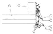
- FIG. 2 is a first sideview of the image rotating device and the camera, to which it is mounted,
- FIG. 3 is a second sideview of the image rotating device and the camera shown in FIG. 2 .
- FIG. 4 is a topview of the image rotating device shown in FIGS. 2 and 3 .
- a digital camera 300 is illustrated in a basic modular form.
- the digital camera 300 is arranged to produce one or several digital image(s) of a generic object 100 , which may be any physical object that is present in a volume optically covered by the digital camera 300 .
- An inventive image rotating device 200 is mounted externally to the digital camera 300 in front of an optical input 400 of the digital camera.
- the optical input 400 is a generally known lens or objective.
- the purpose of the image rotating device 200 is to extend the available field of view of the digital camera 300 in at least one plane, preferably in a horizontal plane as well as in a vertical plane. A preferred embodiment of the image rotating device 200 will be described in more detail with reference to FIGS. 2-4 .
- the digital camera 300 further comprises an image capturing unit 500 , which is provided with appropriate means for producing a digital image representative of the object 100 .
- the image capturing unit 500 comprises a CCD element (Charge Coupled Device), the internal structure of which is believed to be well-known to a man skilled in the art.
- the digital camera 300 also has a controller 600 for controlling the image capturing unit 500 as well as the external image rotating device 200 .
- the controller 600 is operatively connected not only to the device 200 and the unit 500 but also to a digital memory 700 for storing images captured by the image capturing unit 500 .
- the digital camera 300 may comprise an image transforming unit 800 , the purpose of which is to rotate the digital image to compensate for image rotating effects caused by the image rotating device 200 , when the field of view is panned or tilted.
- the image transforming unit 800 is responsive to an angle of rotation of the image rotating device 200 with respect to the objective 400 and uses this angle of rotation when transforming the digital image to compensate for the current pan and/or tilt angle.
- image transforming i.e. to rotate a digital image in one or more than one direction, is believed to be well within reach of a man skilled in the art of digital cameras. Therefore, the internal structure of the image transforming unit 800 will not be described herein.
- the memory 700 may be implemented by any commercially available memory, such as an EEPROM memory.
- the digital camera 300 may be connected to a network 900 , such as an Ethernet or Token Ring network, which in turn may be part of the Internet.
- the controller 600 of the digital camera 300 is provided with appropriate software for allowing the digital camera 300 to act as a web camera available on the network 900 , i.e. a web server that produces digital images.
- the pan and/or tilt angle of the digital camera 300 may be set and changed by a user of the camera by accessing the controller 600 through the network 900 .
- the pan and/or tilt angle(s) may be controlled from a computer directly connected to the digital camera 300 .
- FIGS. 2-4 A preferred embodiment of the image rotating device 200 will now be described in more detail with reference to FIGS. 2-4 .
- the following elements are shown in these drawings:
- the image rotating device 200 has a mirror system, comprising a first fixed mirror 9 and a second tilting mirror 10 .
- the fixed mirror 9 is mounted directly in front of the objective 8 at an angle of 37° relative to the optical center axis of the camera 300 .
- the fixed mirror 9 is mounted to a mirror wheel 5 , which is rotatable around the objective and hence provides a field of view with an angle of rotation of between 0° and 360°.
- the tilting mirror 10 In the center of the field of view the tilting mirror 10 is mounted, so that the axis of rotation thereof is perpendicular to the optical center axis of the camera.
- the tilting mirror 10 is carried on the mirror wheel 5 , thereby causing the tilting mirror 10 to rotate around the objective 8 together with the fixed mirror 9 . Thanks to the geometrical arrangement of the mirrors 9 and 10 with respect to the objective 8 , it is possible to monitor a large volume in a short time.
- the tilting mirror 10 is attached to a mirror holder 11 , which in turn is journalled in the mirror wheel 5 between two fixing parts 2 .
- a slightly smaller guiding wheel 1 is concentrically mounted.
- a tilt shaft 3 is eccentrically mounted to the mirror wheel, so as to cause the tilting mirror 10 to move.
- the guiding wheel 1 transmits its motion to the tilt shaft 3 and from the tilt shaft 3 through a bevel gear 4 to the mirror holder 11 .
- the arrangement resembles a planetary gear, where the guiding wheel represents a sun pinion and the tilt shaft represents a planet pinion.
- the mirror wheel acts as holder of the planet pinion.
- the tilt shaft 3 When the mirror wheel does not move, if the guiding wheel is rotated, the tilt shaft 3 will rotate around its own axis, wherein the mirror holder 11 will be rotated around its axis of rotation. Hence, the tilting mirror 10 is rotated with respect to the mirror wheel 5 , and the center axis of the field of view will be angled with respect to the optical center of the camera. If the mirror wheel 5 and the guiding wheel 1 rotates at the same angular velocity, there will be no relative motion in the tilt shaft and consequently no rotation of the mirror holder/mirror around its axis of rotation. However, the mirror wheel 5 as a whole will rotate with the fixed mirror 9 and the tilting mirror 10 at a constant angle to the optical center axis of the camera.
- the field of view may be rotated 360° for any given tilt angle. Then, if the wheels are rotated relative to each other, the angle of the mirror holder 11 will change, and the field of view may be again be rotated 360° for a new tilt angle. In this way, a very large volume around the camera may be covered, and images may be obtained for any given location within this large volume.
- the mirror wheel 5 and the guiding wheel 1 are driven by respective motors 7 .
- Belt wheels 15 , 17 , timing belts 14 , 16 and timing belt tighteners 13 , 18 are provided, as shown in FIGS. 2-4 .
Abstract
Description
| Qty | Ref. No. | |
||
| 1 | 19 | |
||
| 1 | 18 | | ||
| tightener | ||||
| 1 | 17 | |
||
| 1 | 16 | |
||
| 1 | 15 | |
||
| 1 | 14 | |
||
| 1 | 13 | | ||
| tightener | ||||
| 2 | 12 | |
||
| 1 | 11 | |
||
| 1 | 10 | |
||
| 1 | 9 | Fixed |
||
| 1 | 8 | Camera lens | ||
| (objective) | ||||
| 2 | 7 | |
||
| 1 | 6 | |
||
| 1 | 5 | |
||
| 1 | 4 | |
||
| 1 | 3 | |
||
| 2 | 2 | Fixing |
||
| 1 | 1 | Guiding wheel | ||
-
- Low moment of inertia for rotating parts
- High pan/tilt adjustment speed, short time between angular settings
- High setting accuracy
- Compact design
- Few structural components
- Low manufacturing cost
- Flexible design
- Simple pan/tilt control
- Wide field of view
Claims (1)
Applications Claiming Priority (1)
| Application Number | Priority Date | Filing Date | Title |
|---|---|---|---|
| PCT/SE2000/000522 WO2000057246A1 (en) | 1999-03-19 | 2000-03-17 | A digital camera having panning and/or tilting functionality, and an image rotating device for such a camera |
Publications (1)
| Publication Number | Publication Date |
|---|---|
| US7256834B1 true US7256834B1 (en) | 2007-08-14 |
Family
ID=38337059
Family Applications (1)
| Application Number | Title | Priority Date | Filing Date |
|---|---|---|---|
| US09/700,530 Expired - Fee Related US7256834B1 (en) | 2000-03-17 | 2000-03-17 | Digital camera having panning and/or tilting functionality, and an image rotating device for such a camera |
Country Status (1)
| Country | Link |
|---|---|
| US (1) | US7256834B1 (en) |
Cited By (8)
| Publication number | Priority date | Publication date | Assignee | Title |
|---|---|---|---|---|
| US20080111881A1 (en) * | 2006-11-09 | 2008-05-15 | Innovative Signal Analysis, Inc. | Imaging system |
| US20100321494A1 (en) * | 2009-06-18 | 2010-12-23 | Theia Technologies, Llc | Compact dome camera |
| US20140132828A1 (en) * | 2012-11-14 | 2014-05-15 | The United States of America as represented by the Federal Bureau of Investigation, Department of Ju | Apparatuses for Rotating a Sensing Device |
| US9430923B2 (en) | 2009-11-30 | 2016-08-30 | Innovative Signal Analysis, Inc. | Moving object detection, tracking, and displaying systems |
| US10139819B2 (en) | 2014-08-22 | 2018-11-27 | Innovative Signal Analysis, Inc. | Video enabled inspection using unmanned aerial vehicles |
| US10812727B1 (en) | 2019-12-16 | 2020-10-20 | Cognex Corporation | Machine vision system and method with steerable mirror |
| US11647290B2 (en) | 2019-12-16 | 2023-05-09 | Cognex Corporation | Machine vision system and method with steerable mirror |
| US11790656B2 (en) | 2019-12-16 | 2023-10-17 | Cognex Corporation | Machine vision system and method with steerable mirror |
Citations (22)
| Publication number | Priority date | Publication date | Assignee | Title |
|---|---|---|---|---|
| US3868706A (en) * | 1973-10-12 | 1975-02-25 | Harold Steingold | Television camera mount |
| US3959582A (en) * | 1975-03-31 | 1976-05-25 | The United States Of America As Represented By The Secretary Of The Navy | Solid state electronically rotatable raster scan for television cameras |
| US4153917A (en) * | 1978-01-23 | 1979-05-08 | The United States Of America As Represented By The Secretary Of The Navy | Image stabilizer system for stop-action playback |
| US4322740A (en) | 1979-03-30 | 1982-03-30 | Hitachi, Ltd. | Solid-state color imaging camera |
| US4499490A (en) * | 1982-05-10 | 1985-02-12 | Morgan Jack B | Scanning apparatus with video camera |
| US4576432A (en) * | 1983-08-17 | 1986-03-18 | Messerschmitt-Boelkow-Blohm Gesellschaft Mit Beschraenkter Haftung | Aiming or sighting apparatus with synchronously rotating thermal imager and aiming head |
| US4678289A (en) * | 1984-09-25 | 1987-07-07 | Siemens Aktiengesellschaft | Apparatus for the deflection of a light beam |
| US4933822A (en) | 1986-11-15 | 1990-06-12 | Yoshiro Nakamats | Movable reflecting ray transmitter |
| DE9106075U1 (en) | 1991-05-16 | 1991-07-04 | Liu, Chung-Nan, Tucheng Hsiang, Taipeh, Tw | |
| EP0452188A1 (en) | 1990-04-02 | 1991-10-16 | Sagem SA | Monitoring and imaging device with matrix sensor |
| US5543954A (en) * | 1994-03-01 | 1996-08-06 | Nicholson; James E. | Method and apparatus for selectively scanning for or aiming a signal |
| US5606368A (en) | 1994-10-04 | 1997-02-25 | Boeckeler Instruments, Inc. | Cable-driven pan and tilt mechanism |
| US5717512A (en) * | 1996-05-15 | 1998-02-10 | Chmielewski, Jr.; Thomas A. | Compact image steering and focusing device |
| US5790182A (en) | 1996-08-05 | 1998-08-04 | Interval Research Corp. | System and method for panoramic imaging using concentric spherical mirrors |
| US5805325A (en) * | 1996-10-25 | 1998-09-08 | Lockheed Martin Missiles & Space Co. | Inertially stabilized mirror system |
| US5907433A (en) | 1997-06-16 | 1999-05-25 | Versatron Corporation | Compact variable field of view optical system |
| US5933186A (en) | 1990-09-14 | 1999-08-03 | Fuji Photo Film Co., Ltd. | System for scanning a film image using a mirror |
| US6057915A (en) * | 1996-06-21 | 2000-05-02 | Thermotrex Corporation | Projectile tracking system |
| US6118474A (en) | 1996-05-10 | 2000-09-12 | The Trustees Of Columbia University In The City Of New York | Omnidirectional imaging apparatus |
| US6654063B1 (en) * | 1998-07-31 | 2003-11-25 | Loyal Port Company Limited | Image inverting device |
| US6831693B1 (en) * | 1999-10-27 | 2004-12-14 | Canon Kabushiki Kaisha | Image pickup unit having light incident side reflecting element and drive means for driving reflecting element, and apparatus having same |
| US6963375B1 (en) * | 2000-07-07 | 2005-11-08 | Axis, Ab | Image altering device for an image producing apparatus |
-
2000
- 2000-03-17 US US09/700,530 patent/US7256834B1/en not_active Expired - Fee Related
Patent Citations (22)
| Publication number | Priority date | Publication date | Assignee | Title |
|---|---|---|---|---|
| US3868706A (en) * | 1973-10-12 | 1975-02-25 | Harold Steingold | Television camera mount |
| US3959582A (en) * | 1975-03-31 | 1976-05-25 | The United States Of America As Represented By The Secretary Of The Navy | Solid state electronically rotatable raster scan for television cameras |
| US4153917A (en) * | 1978-01-23 | 1979-05-08 | The United States Of America As Represented By The Secretary Of The Navy | Image stabilizer system for stop-action playback |
| US4322740A (en) | 1979-03-30 | 1982-03-30 | Hitachi, Ltd. | Solid-state color imaging camera |
| US4499490A (en) * | 1982-05-10 | 1985-02-12 | Morgan Jack B | Scanning apparatus with video camera |
| US4576432A (en) * | 1983-08-17 | 1986-03-18 | Messerschmitt-Boelkow-Blohm Gesellschaft Mit Beschraenkter Haftung | Aiming or sighting apparatus with synchronously rotating thermal imager and aiming head |
| US4678289A (en) * | 1984-09-25 | 1987-07-07 | Siemens Aktiengesellschaft | Apparatus for the deflection of a light beam |
| US4933822A (en) | 1986-11-15 | 1990-06-12 | Yoshiro Nakamats | Movable reflecting ray transmitter |
| EP0452188A1 (en) | 1990-04-02 | 1991-10-16 | Sagem SA | Monitoring and imaging device with matrix sensor |
| US5933186A (en) | 1990-09-14 | 1999-08-03 | Fuji Photo Film Co., Ltd. | System for scanning a film image using a mirror |
| DE9106075U1 (en) | 1991-05-16 | 1991-07-04 | Liu, Chung-Nan, Tucheng Hsiang, Taipeh, Tw | |
| US5543954A (en) * | 1994-03-01 | 1996-08-06 | Nicholson; James E. | Method and apparatus for selectively scanning for or aiming a signal |
| US5606368A (en) | 1994-10-04 | 1997-02-25 | Boeckeler Instruments, Inc. | Cable-driven pan and tilt mechanism |
| US6118474A (en) | 1996-05-10 | 2000-09-12 | The Trustees Of Columbia University In The City Of New York | Omnidirectional imaging apparatus |
| US5717512A (en) * | 1996-05-15 | 1998-02-10 | Chmielewski, Jr.; Thomas A. | Compact image steering and focusing device |
| US6057915A (en) * | 1996-06-21 | 2000-05-02 | Thermotrex Corporation | Projectile tracking system |
| US5790182A (en) | 1996-08-05 | 1998-08-04 | Interval Research Corp. | System and method for panoramic imaging using concentric spherical mirrors |
| US5805325A (en) * | 1996-10-25 | 1998-09-08 | Lockheed Martin Missiles & Space Co. | Inertially stabilized mirror system |
| US5907433A (en) | 1997-06-16 | 1999-05-25 | Versatron Corporation | Compact variable field of view optical system |
| US6654063B1 (en) * | 1998-07-31 | 2003-11-25 | Loyal Port Company Limited | Image inverting device |
| US6831693B1 (en) * | 1999-10-27 | 2004-12-14 | Canon Kabushiki Kaisha | Image pickup unit having light incident side reflecting element and drive means for driving reflecting element, and apparatus having same |
| US6963375B1 (en) * | 2000-07-07 | 2005-11-08 | Axis, Ab | Image altering device for an image producing apparatus |
Cited By (18)
| Publication number | Priority date | Publication date | Assignee | Title |
|---|---|---|---|---|
| US9413956B2 (en) | 2006-11-09 | 2016-08-09 | Innovative Signal Analysis, Inc. | System for extending a field-of-view of an image acquisition device |
| US20100073475A1 (en) * | 2006-11-09 | 2010-03-25 | Innovative Signal Analysis, Inc. | Moving object detection |
| US8072482B2 (en) * | 2006-11-09 | 2011-12-06 | Innovative Signal Anlysis | Imaging system having a rotatable image-directing device |
| US8670020B2 (en) | 2006-11-09 | 2014-03-11 | Innovative Systems Analysis, Inc. | Multi-dimensional staring lens system |
| US20080111881A1 (en) * | 2006-11-09 | 2008-05-15 | Innovative Signal Analysis, Inc. | Imaging system |
| US8792002B2 (en) | 2006-11-09 | 2014-07-29 | Innovative Signal Analysis, Inc. | System for extending a field-of-view of an image acquisition device |
| US8803972B2 (en) | 2006-11-09 | 2014-08-12 | Innovative Signal Analysis, Inc. | Moving object detection |
| US20100321494A1 (en) * | 2009-06-18 | 2010-12-23 | Theia Technologies, Llc | Compact dome camera |
| US10510231B2 (en) | 2009-11-30 | 2019-12-17 | Innovative Signal Analysis, Inc. | Moving object detection, tracking, and displaying systems |
| US9430923B2 (en) | 2009-11-30 | 2016-08-30 | Innovative Signal Analysis, Inc. | Moving object detection, tracking, and displaying systems |
| US9106814B2 (en) * | 2012-11-14 | 2015-08-11 | The United States of America as represented by the Federal Bureau of Investigation, Dept. of Justice | Apparatuses for rotating a sensing device |
| US20140132828A1 (en) * | 2012-11-14 | 2014-05-15 | The United States of America as represented by the Federal Bureau of Investigation, Department of Ju | Apparatuses for Rotating a Sensing Device |
| US10139819B2 (en) | 2014-08-22 | 2018-11-27 | Innovative Signal Analysis, Inc. | Video enabled inspection using unmanned aerial vehicles |
| US10812727B1 (en) | 2019-12-16 | 2020-10-20 | Cognex Corporation | Machine vision system and method with steerable mirror |
| US11240436B2 (en) | 2019-12-16 | 2022-02-01 | Cognex Corporation | Machine vision system and method with steerable mirror |
| US11647290B2 (en) | 2019-12-16 | 2023-05-09 | Cognex Corporation | Machine vision system and method with steerable mirror |
| US11790656B2 (en) | 2019-12-16 | 2023-10-17 | Cognex Corporation | Machine vision system and method with steerable mirror |
| US11803049B2 (en) | 2019-12-16 | 2023-10-31 | Cognex Corporation | Machine vision system and method with steerable mirror |
Similar Documents
| Publication | Publication Date | Title |
|---|---|---|
| US6963375B1 (en) | Image altering device for an image producing apparatus | |
| US4963962A (en) | Optical surveillance assembly and camera | |
| JPH07234447A (en) | Photographic unit and camera | |
| JPH0635022A (en) | Correcting lens driving mechanism for image blurring correcting device for camera | |
| US7256834B1 (en) | Digital camera having panning and/or tilting functionality, and an image rotating device for such a camera | |
| JP2541924B2 (en) | Imaging optical device | |
| EP1166178B1 (en) | A digital camera having panning and/or tilting functionality, and an image rotating device for such a camera | |
| JP3489531B2 (en) | Two-axis drive mechanism, image input device and light projection device using the same | |
| CN111064933A (en) | Infrared panoramic monitoring system | |
| US6844912B2 (en) | Optical system for the rotation of images taken by a film camera about the optical axis | |
| JP2003185902A (en) | Camera | |
| CN107870414A (en) | Panoramic scanning bogey | |
| JPH0495489A (en) | Stereoscopic video image pickup device | |
| JPH07322104A (en) | Monitoring device | |
| US6891643B1 (en) | Imaging device and imaging method | |
| JP3187157B2 (en) | Image monitoring device | |
| US20220223016A1 (en) | Image capturing apparatus | |
| RU2055381C1 (en) | Device for stabilizing optical image | |
| CN216565304U (en) | Video camera | |
| JPH07170435A (en) | Camera | |
| JPS6067240A (en) | Rearward observing apparatus equipped with positive situation image correcting device for car | |
| JPH11289483A (en) | Cctv device | |
| JP3200505B2 (en) | Head device | |
| WO2023281309A1 (en) | Shaped-aperture scanning aerial cameras | |
| JP2001352470A (en) | Imaging device |
Legal Events
| Date | Code | Title | Description |
|---|---|---|---|
| AS | Assignment |
Owner name: AXIS AB, SWEDEN Free format text: ASSIGNMENT OF ASSIGNORS INTEREST;ASSIGNORS:SAGEFALK, WILLY;ABRAHAMSSON, LARS;REEL/FRAME:011510/0613 Effective date: 20010108 |
|
| FEPP | Fee payment procedure |
Free format text: PAYER NUMBER DE-ASSIGNED (ORIGINAL EVENT CODE: RMPN); ENTITY STATUS OF PATENT OWNER: LARGE ENTITY Free format text: PAYOR NUMBER ASSIGNED (ORIGINAL EVENT CODE: ASPN); ENTITY STATUS OF PATENT OWNER: LARGE ENTITY |
|
| CC | Certificate of correction | ||
| FPAY | Fee payment |
Year of fee payment: 4 |
|
| REMI | Maintenance fee reminder mailed | ||
| LAPS | Lapse for failure to pay maintenance fees | ||
| STCH | Information on status: patent discontinuation |
Free format text: PATENT EXPIRED DUE TO NONPAYMENT OF MAINTENANCE FEES UNDER 37 CFR 1.362 |
|
| FP | Lapsed due to failure to pay maintenance fee |
Effective date: 20150814 |