US7257262B2 - Moving image coding method and apparatus for determining a position of a macro block which is intra-coded or inter-coded - Google Patents
Moving image coding method and apparatus for determining a position of a macro block which is intra-coded or inter-coded Download PDFInfo
- Publication number
- US7257262B2 US7257262B2 US10/644,854 US64485403A US7257262B2 US 7257262 B2 US7257262 B2 US 7257262B2 US 64485403 A US64485403 A US 64485403A US 7257262 B2 US7257262 B2 US 7257262B2
- Authority
- US
- United States
- Prior art keywords
- coding
- macro block
- inter
- image
- frame
- Prior art date
- Legal status (The legal status is an assumption and is not a legal conclusion. Google has not performed a legal analysis and makes no representation as to the accuracy of the status listed.)
- Expired - Fee Related, expires
Links
Images


Classifications
-
- H—ELECTRICITY
- H04—ELECTRIC COMMUNICATION TECHNIQUE
- H04N—PICTORIAL COMMUNICATION, e.g. TELEVISION
- H04N19/00—Methods or arrangements for coding, decoding, compressing or decompressing digital video signals
- H04N19/42—Methods or arrangements for coding, decoding, compressing or decompressing digital video signals characterised by implementation details or hardware specially adapted for video compression or decompression, e.g. dedicated software implementation
- H04N19/423—Methods or arrangements for coding, decoding, compressing or decompressing digital video signals characterised by implementation details or hardware specially adapted for video compression or decompression, e.g. dedicated software implementation characterised by memory arrangements
- H04N19/426—Methods or arrangements for coding, decoding, compressing or decompressing digital video signals characterised by implementation details or hardware specially adapted for video compression or decompression, e.g. dedicated software implementation characterised by memory arrangements using memory downsizing methods
-
- H—ELECTRICITY
- H04—ELECTRIC COMMUNICATION TECHNIQUE
- H04N—PICTORIAL COMMUNICATION, e.g. TELEVISION
- H04N19/00—Methods or arrangements for coding, decoding, compressing or decompressing digital video signals
- H04N19/10—Methods or arrangements for coding, decoding, compressing or decompressing digital video signals using adaptive coding
- H04N19/134—Methods or arrangements for coding, decoding, compressing or decompressing digital video signals using adaptive coding characterised by the element, parameter or criterion affecting or controlling the adaptive coding
- H04N19/142—Detection of scene cut or scene change
-
- H—ELECTRICITY
- H04—ELECTRIC COMMUNICATION TECHNIQUE
- H04N—PICTORIAL COMMUNICATION, e.g. TELEVISION
- H04N19/00—Methods or arrangements for coding, decoding, compressing or decompressing digital video signals
- H04N19/10—Methods or arrangements for coding, decoding, compressing or decompressing digital video signals using adaptive coding
- H04N19/134—Methods or arrangements for coding, decoding, compressing or decompressing digital video signals using adaptive coding characterised by the element, parameter or criterion affecting or controlling the adaptive coding
- H04N19/146—Data rate or code amount at the encoder output
- H04N19/152—Data rate or code amount at the encoder output by measuring the fullness of the transmission buffer
-
- H—ELECTRICITY
- H04—ELECTRIC COMMUNICATION TECHNIQUE
- H04N—PICTORIAL COMMUNICATION, e.g. TELEVISION
- H04N19/00—Methods or arrangements for coding, decoding, compressing or decompressing digital video signals
- H04N19/10—Methods or arrangements for coding, decoding, compressing or decompressing digital video signals using adaptive coding
- H04N19/134—Methods or arrangements for coding, decoding, compressing or decompressing digital video signals using adaptive coding characterised by the element, parameter or criterion affecting or controlling the adaptive coding
- H04N19/164—Feedback from the receiver or from the transmission channel
-
- H—ELECTRICITY
- H04—ELECTRIC COMMUNICATION TECHNIQUE
- H04N—PICTORIAL COMMUNICATION, e.g. TELEVISION
- H04N19/00—Methods or arrangements for coding, decoding, compressing or decompressing digital video signals
- H04N19/60—Methods or arrangements for coding, decoding, compressing or decompressing digital video signals using transform coding
- H04N19/61—Methods or arrangements for coding, decoding, compressing or decompressing digital video signals using transform coding in combination with predictive coding
Definitions
- the present invention relates to moving image coding method and apparatus for executing the compression coding of a moving image by suitably switching intra coding which utilizes spatial redundancy in a frame and inter coding which utilizes temporal redundancy between frames.
- FIG. 30 is a block diagram showing an example of the configuration of a conventional moving image apparatus (encoder).
- a reference number 101 denotes an image input unit
- 103 denotes a discrete cosine transform (DCT) unit for performing orthogonal transformation
- 104 denotes a quantizer
- 105 denotes a Huffman encoder for executing variable-length coding
- 106 denotes a dequantizer
- 107 denotes a inverse DCT unit for performing inverse orthogonal transformation
- 108 denotes a reference image memory
- 109 denotes a motion compensator
- 110 denotes a motion detector
- 3011 denotes a memory controller.
- intra coding is executed in the moving image coding apparatus configured as shown in FIG. 30 , intra coding utilizing spatial redundancy in an image frame is executed by performing orthogonal transformation in the DCT unit 103 every macro block of a present image input from the image input unit 101 , executing quantization in the quantizer 104 and executing variable-length coding in the Huffman encoder 105 .
- a reference image is generated by executing inverse quantization for data after quantization in the dequantizer 106 and performing inverse orthogonal transformation in the inverse DCT unit 107 and is stored in the reference image memory 108 .
- a present image frame input from the image input unit 101 is compared with a reference image frame stored in the reference image memory 108 in the motion detector 110 and a motion vector is acquired every macro block or every frame. Further, motion compensation using the motion vector is performed for the reference image frame in the motion compensator 109 and a predictive image frame is generated.
- inter coding utilizing temporal redundancy between image frames is executed by applying orthogonal transformation to difference between a present image frame and a predictive image frame every macro block in the DCT unit 103 , quantizing the result in the quantizer 104 and coding the result in variable length in the Huffman encoder 105 .
- a reference image is generated by applying inverse quantization to data after quantization in the dequantizer 106 , performing inverse orthogonal transformation in the inverse DCT unit 107 and further, adding to motion compensated predictive data output from the motion compensator 109 and is stored in the reference image memory 108 .
- macro blocks of the reference image are generated for all macro blocks in the present image frame for which intra coding and inter coding are performed and are stored in the reference image memory 108 .
- a series of processing that generates a reference image based upon data after inverse quantization is called local decoding.
- predictive coding using a reference image in the compression coding of a moving image is the base of the technique and as further complex predictive coding is used in moving image coding for television broadcasting, various trial for efficiently controlling a buffer memory which has been used for a reference image memory is made (for example, refer to JP-A-11-313327).
- JP-A-11-313327 A related reference with respect to the application is JP-A-11-313327.
- a mass-storage reference image memory according to large screen size is further required to be provided to also enable the moving image coding of the large screen size (a large number of pixels) in the same apparatus and there is a problem that the system cost is increased.
- the object of the invention is to provide moving image coding method and apparatus, performing compression coding for moving images with intra coding and inter coding, which enable the reduction of the capacity of a reference image memory with keeping suitable coding efficiency and suitable image quality according to use to reduce the cost of the moving image coding apparatus.
- the invention provides a moving image coding method for coding a moving image, every macro block which forms a predetermined area of a present image, with using intra coding in which image data are orthogonal-transformed, and then image data after the orthogonal-transformation are quantized and variable-length coded, and inter coding in which a motion vector of the present image relative to a reference image is detected, motion compensation for the reference image with using the motion vector is performed, differential data between the present image and the reference image after the motion compensation are orthogonal-transformed, and then differential data after the orthogonal transformation are quantized and variable-length coded, and for storing, for purpose of the inter coding, a reference image of image frame next to the present image generated by inverse-quantizing and inverse-orthogonal-transforming image data after the quantization or differential data after the quantization in a reference image memory, comprising the step of: determining position of a macro block which is intra-coded or inter-coded, in a range of the maximum number of macro blocks inter-code
- reference image of all macro blocks in the current frame are not required to be prepared by determining position of a macro block which is intra-coded or inter-coded when an image prior to the present image is coded. Therefore, the capacity of the reference image memory can be reduced.
- macro blocks in a reference image of the next image frame for only position of which is determined to perform the inter coding, are stored in the reference image memory.
- macro blocks of the reference image stored in the reference image memory can be limited. Therefore, the capacity of the reference image memory can be reduced.
- the maximum number of macro blocks which is inter-coded is below the number of macro blocks configuring an image frame.
- memory capacity can be reduced according to the maximum number of macro blocks.
- the maximum number of macro blocks which is inter-coded is suitably determined based upon available capacity of the reference image memory.
- the maximum number of macro blocks which is inter-coded is set according to the size of a variable-length area provided in another memory and available as the reference image memory, the number of macro blocks which is inter-coded can be also made substantially equal to the number of total macro blocks configuring an image frame in the case the available area is large. Therefore, maximum coding efficiency can be dynamically realized according to a state in which the apparatus is used.
- the orthogonal transformation is a discrete cosine transform (DCT)
- the variable-length coding is Huffman coding.
- position of a macro block which is intra-coded or inter-coded in Nth frame is determined based upon at least one of evaluations of image information and code quantity at a time of coding of an image in or prior to (N ⁇ 1)th frame.
- encoded macro block position is determined based upon image information and the code quantity in coding, coding efficiency and image quality can be enhanced.
- position of a macro block which is intra-coded or inter-coded in Nth frame is determined in or prior to (N ⁇ 1)th fame by an external.
- coding according to a type of a moving image can be determined.
- the macro block is intra-coded based on an instruction for stopping inter coding at a time of coding of macro block identically positioned in a macro block for which inter coding is determined to be performed in or prior to (N ⁇ 1)th frame.
- coding suitable for a moving image can be determined by determining coding in a current frame again.
- position of a macro block which is intra-coded or inter-coded in Nth frame is determined based upon at least one of evaluations of image information and total code quantity of all macro blocks in (N ⁇ 2)th frame at a time of coding of (N ⁇ 1)th frame.
- the configuration as determination related to the whole image frame such as the switching of a macro block position for which intra coding is performed in the next Nth frame and a macro block position for which inter coding is performed in the next Nth frame can be made in coding in the (N ⁇ 1)th frame, in the case all code quantity is judged excessive as a result of coding in the (N ⁇ 2)th frame for example, coding efficiency can be enhanced.
- position of a macro block which is intra-coded or inter-coded in Nth frame is determined based upon at least one of evaluations of image information and code quantity of every macro block in (N ⁇ 1)th frame.
- a macro block position for which intra coding or inter coding is performed in the next frame can be determined based upon image information and the quantity of codes every macro block in coding in the (N ⁇ 1)th frame. Therefore, coding efficiency can be enhanced.
- macro blocks which is intra-coded or inter-coded is provided in a form of a pattern having staggered arrangement.
- the bias of the quantity of codes in coding can be reduced.
- inter coding is performed for the macro blocks to be encoded with zero as the motion vector.
- inter coding can be simplified by applying inter coding with a motion vector as a zero vector.
- macro blocks for which inter coding is performed corresponds in the case a macro block position for which inter coding is performed is provided in the form of a pattern having staggered arrangement.
- position information of macro blocks stored in the reference image memory is held.
- intra coding is performed, in Nth frame, for the macro block identically positioned in the macro block for which the inter coding is performed in the (N ⁇ 1)th frame.
- the configuration as it is considered that the motion of the macro block is large (the motion is hard) in the case the performance function value is larger than the predetermined threshold and it is predicted that the quantity of codes increases due to an error of motion detection in the case inter coding is continuously performed for the macro block position in the next frame, it is judged that there is not large difference in coding efficiency even if intra coding which is generally considered more unsatisfactory in coding efficiency than inter coding is performed instead and image quality can be enhanced by applying intra coding to a macro block in the macro block position.
- the reference image memory can have an extra by quantity in which intra coding is performed instead and coding efficiency can be synthetically enhanced by producing an extra for applying inter coding to macro blocks in another macro block position.
- intra coding is performed for a macro block, which is positioned in a subsequent macro block, in the next image frame.
- the number of macro blocks which enables to be stored in the reference image memory can be controlled.
- intra coding is performed for a macro block identically positioned in the macro block for which the inter coding is performed in the (N ⁇ 1)th frame in Nth frame.
- inter coding is performed, in Nth frame, for the macro block identically positioned in the macro block for which the intra coding is performed in the (N ⁇ 1)th frame.
- the current state is a state close to a static image in which the motion of macro blocks is small
- the motion of macro blocks for which these macro blocks are adjacent and for which intra coding is performed may be also possibly small in consideration of spatial correlation and it can be judged that the motion in the next frame is also small in consideration of temporal correlation, coding efficiency can be enhanced by applying inter coding to macro blocks in the macro block position in the next frame.
- inter coding is performed, in Nth frame, for the macro block identically positioned in the macro block for which the intra coding is performed in the (N ⁇ 1)th frame.
- coding efficiency can be enhanced by applying inter coding to macro blocks in the macro block position in the next frame.
- inter coding is performed, in Nth frame, for the macro block identically positioned in the macro block for which the intra coding is performed in the (N ⁇ 1)th frame.
- coding efficiency is generally unsatisfactory in intra coding, compared with inter coding though the continuous application of intra coding to a macro block position may be determined in the case no macro block for which inter coding is performed is adjacent, encoding efficiency can be enhanced by applying inter coding once per a few frames.
- motion information of a target area for which intra coding is performed is provided in (N ⁇ 1)th frame; intra coding is performed, in Nth frame, for a macro block identically positioned in a macro block which is predicted to be the target area in Nth frame; and inter coding is performed, in Nth frame, for a macro block in the periphery of the macro block.
- macro blocks of a reference image are generated for all positions of a macro block and are stored in the reference image memory; and in a case of coding a moving image in which image frame is configured by macro blocks which number exceeds the maximum number of inter-coded macro blocks, macro blocks of a reference image are generated for only position of a macro block which is determined to be performed inter coding and are stored in the reference image memory.
- moving image coding in plural image sizes by a simple system is enabled.
- the number of macro blocks for which inter coding is performed is not limited and normal moving image coding is enabled in the case of a CIF image the number of macro blocks of which is 396 in the case the number of maximum macro blocks for which inter coding is performed is 400 and the corresponding reference image memory is provided
- the number of macro blocks for which inter coding is performed is limited and moving image coding is enabled in the case of a VGA image the number of macro blocks of which is 1200
- moving image coding in both image sizes is enabled by the simple system for reducing the cost of the reference image memory.
- a frequency of inter coding is held every position of macro blocks; and in starting, inter coding is performed for macro blocks from a macro block positioned where a frequency of inter coding is more in order.
- subsequent image quality and coding efficiency can be made satisfactory by previously applying inter coding to the macro block in the macro block position for which inter coding is frequently performed in initialization. For example, in the case of an image from a fixed monitoring camera, as inter coding is previously allocated to a macro block in a macro block position in which motion is small, coding efficiency after reactivation is enhanced.
- the configuration holding the frequency of inter coding and the precedent allocation of inter coding can be selected, image quality and coding efficiency can be improved by previously allocating inter coding to the macro block in the macro block position for which inter coding is frequently performed in the case of use for a fixed monitoring camera for example, and in the case of use for a mobile camera, as these functions are not effective, coding according to application is enabled by coding without selection.
- intra coding is performed for all macro block in the Nth frame.
- macro block positions for which intra coding or inter coding is performed in the next frame can be set to staggered arrangement by detecting the scene change and applying intra coding to the macro blocks in all the macro block positions when the scene change occurs and subsequent coding efficiency can be enhanced.
- the invention provides a moving image coding method for coding a moving image, every macro block which forms a predetermined area of a present image, with using intra coding in which image data are orthogonal-transformed, and then image data after the orthogonal-transformation are quantized, and variable-length coded, and inter coding in which a motion vector of the present image relative to a reference image is detected, motion compensation for the reference image with using the motion vector is performed, differential data between the present image and the reference image after the motion compensation are orthogonal-transformed, and then differential data after the orthogonal transformation are quantized and variable-length coded, and for storing, for purpose of the inter coding, a reference image of image frame next to the present image generated by inverse-quantizing and inverse-orthogonal-transforming image data after the quantization or differential data after the quantization in a reference image memory, comprising the step of: determining position of a macro block which is intra-coded or inter-coded in a predetermined pattern.
- the bias of the quantity of codes in coding is reduced and coding efficiency can be enhanced by giving the pattern of the suitable macro block position.
- the predetermined pattern is a pattern where macro blocks which is inter-coded are arranged in staggered format.
- the bias of the quantity of codes in coding can be minimized by providing the pattern in which the macro block position for which inter coding is performed is expressed in the staggered arrangement as an initial value.
- the predetermined pattern is a pattern where macro blocks which is inter-coded are arranged in lattice format.
- the bias of the quantity of codes in coding is reduced by providing the pattern in which the macro block position for which inter coding is performed is expressed in the lattice arrangement as an initial value and coding efficiency can be enhanced because opportunities for motion detection in coding increase.
- the invention provides a moving image coding apparatus provided with encoding means for encoding a moving image, every macro block which forms a predetermined area of a present image, with using intra coding for in which image data are orthogonal-transformed, and then image data after the orthogonal transformation are quantized and variable-length coded, and inter coding in which a motion vector of the present image relative to a reference image is detected, motion compensation for the reference image with using the motion vector is performed, differential data between the present image and the reference image after the motion compensation are orthogonal-transformed, and then differential data after the orthogonal transformation are quantized and variable-length coded, and a reference image memory for storing, for purpose of the inter coding, a reference image of image frame next to the present image generated by inverse-quantizing and inverse-orthogonal-transforming image data after the quantization or differential data after the quantization, comprising: determining means for determining position of a macro block which is intra-coded or inter-coded in a range of the maximum number of
- reference images of all macro blocks are not required to be prepared in the current frame by determining the macro block position for which intra coding or inter coding is performed in the coding of the image prior to the present image and the capacity of the reference image memory can be reduced.
- the reference image memory stores macro blocks in a reference image of the next image frame, for only position of which is determined to perform the inter coding.
- the macro blocks of the reference image stored in the reference image memory can be limited. Therefore, the capacity of the reference image memory can be reduced.
- the reference image memory has smaller capacity than capacity required to store a reference image for all macro blocks configuring an image frame.
- address management means for managing position of a macro block in a reference image stored in the reference image memory in correspondence with an address of the reference image memory.
- macro block number counting means for counting the number of macro blocks in a reference image stored in the reference image memory.
- the determining means determines to intra code for a macro block, which is positioned in a subsequent macro block, in the next image frame.
- the number of macro blocks which enables to be stored in the reference image memory can be managed.
- function value calculating means for calculating evaluation function value based upon difference between a macro block identically positioned in a macro block for which inter coding is performed and a macro block in a reference image stored in the reference image memory.
- the determining means performs intra coding for a macro block identically positioned in the macro block for which the inter coding is performed in a next image frame, in a case the evaluation function value is larger than a predetermined threshold.
- the reference image memory can have space by the quantity of the application of intra coding and synthetic coding efficiency can be enhanced by producing free space for inter coding performed for macro blocks in another macro block position.
- inter coding frequency counting means for counting a frequency of continuous inter coding in each position of a macro block.
- the determining means performs intra coding for a macro block positioned where the frequency of continuous inter coding is equal to a predetermined threshold in the next image frame.
- intra coding frequency counting means for counting a frequency of continuous intra coding in each position of a macro block.
- the determining means performs inter coding for a macro block positioned where the frequency of continuous intra coding is equal to a predetermined threshold in the next image frame, in a case the number of macro blocks stored in the reference image memory is smaller than the maximum number of macro blocks which can be stored in the reference image memory.
- coding efficiency can be enhanced by applying inter coding once per a few frames.
- the coding means performs inter coding for a macro block adjacent to all or over-predetermined number of a macro block which is intra-coded with zero as the motion vector.
- inter coding in the case an object hardly with a motion is photographed by a fixed monitoring camera for example, inter coding can be simplified by inhibiting a function for motion compensation and inter coding with a motion vector zero.
- the invention provides a semiconductor integrated circuit, comprising the moving image coding apparatus.
- the integrated circuit wherein the reduction of the number of terminals of a chip, the miniaturization of a substrate of the reference image memory, the reduction of power consumption between pads and the acceleration of processing speed are enabled by building the reference image memory the capacity of which can be reduced in the semiconductor integrated circuit can be realized.
- FIG. 1 is a block diagram showing the configuration of a moving image coding apparatus equivalent to a first embodiment of the invention
- FIG. 2 is an explanatory drawing for explaining recording control over a reference image memory in the first embodiment of the invention
- FIG. 3 is a block diagram showing the configuration of a moving image coding apparatus equivalent to a second embodiment of the invention
- FIG. 4 is an explanatory drawing for explaining recording control over a reference image memory in the second embodiment of the invention.
- FIG. 5 is a block diagram showing the configuration of a moving image coding apparatus equivalent to a third embodiment of the invention.
- FIG. 6 is an explanatory drawing for explaining recording control over a reference image memory in the third embodiment of the invention.
- FIG. 7 is a block diagram showing the configuration of a moving image coding apparatus equivalent to a fourth embodiment of the invention.
- FIG. 8 is an explanatory drawing for explaining moving image coding control in the fourth embodiment of the invention.
- FIG. 9 is a block diagram showing the configuration in which moving image coding is simplified of the moving image coding apparatus equivalent to the fourth embodiment of the invention.
- FIG. 10 shows an example of an initialization pattern of a macro block position for which intra coding or inter coding is performed
- FIG. 11 is a block diagram showing the configuration of a moving image coding apparatus equivalent to a fifth embodiment of the invention.
- FIG. 12 is an explanatory drawing for explaining moving image coding control in the fifth embodiment of the invention.
- FIG. 13 is a block diagram showing the configuration of a moving image coding apparatus equivalent to a sixth embodiment of the invention.
- FIG. 14 is an explanatory drawing for explaining moving image coding control for determining a differential value between inter coding macro blocks in the sixth embodiment of the invention.
- FIG. 15 is an explanatory drawing for explaining moving image coding control for determining a differential value between inter coding macro blocks in the sixth embodiment of the invention.
- FIG. 16 is an explanatory drawing for explaining moving image coding control for determining a frequency of continuous inter coding in the sixth embodiment of the invention.
- FIG. 17 is an explanatory drawing for explaining moving image coding control for determining a differential value between inter coding macro blocks adjacent to an intra coding macro block in the sixth embodiment of the invention.
- FIG. 18 is an explanatory drawing for explaining moving image coding control for determining the quantity of codes in an intra coding macro block in the sixth embodiment of the invention.
- FIG. 19 is an explanatory drawing for explaining moving image coding control for determining a frequency of continuous intra coding in the sixth embodiment of the invention.
- FIG. 20 is a block diagram showing the configuration of a moving image coding apparatus equivalent to a seventh embodiment of the invention.
- FIG. 21 is an explanatory drawing for explaining moving image coding control in the seventh embodiment of the invention.
- FIG. 22 is an explanatory drawing for explaining moving image coding control in the case a target shifts upward in the seventh embodiment of the invention.
- FIG. 23 is an explanatory drawing for explaining moving image coding control in the case the target shifts leftward in the seventh embodiment of the invention.
- FIG. 24 is an explanatory drawing for explaining moving image coding control in the case the target shifts downward in the seventh embodiment of the invention.
- FIG. 25 is an explanatory drawing for explaining moving image coding control in the case the target shifts rightward in the seventh embodiment of the invention.
- FIG. 26 is a block diagram showing the configuration of a moving image coding apparatus equivalent to an eighth embodiment of the invention.
- FIG. 27 is an explanatory drawing for explaining moving image coding control in the eighth embodiment of the invention.
- FIG. 28 is a block diagram showing the configuration of a moving image coding apparatus equivalent to a ninth embodiment of the invention.
- FIG. 29 is a block diagram showing the configuration of a moving image coding apparatus equivalent to a tenth embodiment of the invention.
- FIG. 30 is a block diagram showing the configuration of a conventional moving image coding apparatus.
- thresholds used in the following embodiments are values for explanation and do not limit the embodiments of the invention.
- another orthogonal transformation technique may be also used for orthogonal transformation in place of DCT in the following embodiments and another variable-length coding technique may be also used for variable-length coding in place of Huffman coding.
- FIG. 1 is a block diagram showing the configuration of a moving image coding apparatus equivalent to a first embodiment of the invention.
- the same reference number is allocated to the same part as the part in the conventional moving image coding apparatus shown in FIG. 30 .
- a reference number 101 denotes an image input unit
- 103 denotes a DCT unit that performs orthogonal transformation
- 104 denotes a quantizer
- 105 denotes a Huffman encoder that executes variable-length coding
- 106 denotes a dequantizer
- 107 denotes a inverse DCT unit that performs inverse orthogonal transformation
- 108 denotes a reference image memory
- 109 denotes a motion compensator
- 110 denotes a motion detector
- 111 denotes a memory controller.
- the number of maximum macro blocks for which inter coding is performed in one image frame is set to a smaller value than the number of macro blocks configuring an image frame and in a range of the set number of maximum macro blocks, macro block positions for which inter coding is performed in the next frame are determined.
- the reference image memory is not required to be a frame memory for recording a reference image of the whole one image frame and can be configured with capacity required for the number of maximum macro blocks for which inter coding is performed.
- FIG. 1 a state in which the memory controller 111 executes recording control for recording only macro blocks for which inter coding is performed in the next frame in the reference image memory 108 is schematically shown by a switching function (SW).
- SW switching function
- FIG. 2 is an explanatory drawing for explaining recording control over the reference image memory in this embodiment.
- a moving image in FIG. 2 is constituted by common intermediate format (CIF) (macro blocks: 22 ⁇ 18 pieces) images, the ratio of macro blocks for which intra coding is performed and macro blocks for which inter coding is performed inter coding is 50% to 50%, a layout composed of macro block positions for which intra coding is performed is shown on the left side of a frame (a screen) and a layout composed of macro block positions for which inter coding is performed is shown on the right side of the frame (the screen).
- CIF common intermediate format
- the capacity of the reference image memory 108 can be reduced to capacity equivalent to a half of a conventional frame memory 204 that can record reference images in all macro block positions.
- a concrete example of moving image coding will be described below.
- intra coding is performed for all macro blocks.
- a reference image is recorded into the reference image memory 108 , however, for the group of macro blocks 201 in macro block positions for which intra coding is performed in a second frame, reference image macro blocks are not recorded and for a group of macro blocks 202 in macro block positions for which inter coding is performed in the second frame, a group of reference image macro blocks 203 are generated and recorded.
- next second frame for a group of a macro block in a macro block position for which intra coding is performed, the similar coding to that in the first frame is repeated, for a group of macro blocks 205 in a macro block position for which inter coding is performed, the group of reference image macro blocks 203 recorded into the reference image memory 108 is read, motion detection is performed by the motion detector 110 , motion compensation is performed using a motion vector acquired in the motion detection by the motion compensator 109 and macro blocks of a predictive image are generated.
- the differential data is encoded by the DCT unit 103 , the quantizer 104 and the Huffman encoder 105 and inter coding data is acquired.
- reference image macro blocks for macro blocks for which inter coding is performed in a third frame are generated and are recorded into the reference image memory 108 .
- the reference image macro block data recorded into the reference image memory 108 is recorded at the same address every macro block. That is, as the reference image macro blocks are overwritten in the same position every processing, the capacity of the reference image memory 108 may be always fixed.
- Moving image coding shown in FIG. 2 is executed by also repeating the similar operation to that in the second frame in the third frame and in subsequent frames and executing subsequent coding so that intra coding is performed for macro blocks on the left side of the frame and inter coding is performed for macro blocks on the right side.
- intra coding macro block positions and inter coding macro block positions are arranged on the left side and the right side of the screen.
- This embodiment is not limited to the right and left sides or the upside and the downside of the screen and the two parts.
- the number of divisions is increased, a range of motion detection is narrowed, the precision of motion detection may be deteriorated and further, memory control is also complex.
- the capacity of the reference image memory can be reduced by recording only reference image a macro block in a macro block position for which inter coding is performed in the next frame in the reference image memory and a low-cost moving image coding system can be realized.
- FIG. 3 is a block diagram showing the configuration of a moving image coding apparatus equivalent to a second embodiment of the invention. As shown in FIG. 3 , the same reference number is allocated to the same part as the part in the moving image coding apparatus equivalent to the first embodiment shown in FIG. 1 .
- the arrangement of a macro block position for which intra coding is performed and a macro block position for which inter coding is performed is specified from an external.
- an inter coding instruction signal 301 from the external is input to a memory controller 111 .
- FIG. 4 is an explanatory drawing for explaining recording control over a reference image memory in this embodiment.
- a group of macro blocks 401 for which intra coding is performed is shown on the left side of the frame
- a group of macro blocks 402 for which inter coding is performed is shown on the right side
- a group of reference image macro blocks 405 in a macro block position for which inter coding is performed in the (N ⁇ 1)th frame is recorded into the reference image memory 108 .
- the inter coding instruction signal 301 is input from the external and an instruction for changing so that a macro block position for which inter coding is performed is located on the left side of a frame and a macro block position for which intra coding is performed is located on the right side in the Nth frame is transmitted to the memory controller 111 .
- the group of macro blocks 402 for which inter coding is performed is encoded using the group of reference image macro blocks 405 recorded into the reference image memory 108 .
- the group of macro blocks 401 for which intra coding is performed is encoded.
- the reason why the coding of a macro block for which inter coding is performed is previously executed is that as a macro block position for which intra coding is performed in the (N ⁇ 1)th frame is equivalent to a macro block position for which inter coding is performed in the Nth frame, a group of reference image macro blocks 406 in a macro block position for which inter coding is performed in the Nth frame is required to be recorded into the reference image memory 108 .
- the capacity of the reference image memory 108 is fixed without being increased by previously using the group of reference image macro blocks 405 recorded into the reference image memory 108 and overwriting the group of reference image macro blocks 406 for inter coding in the Nth frame on it.
- the capacity of the reference image memory can be reduced as in the first embodiment by writing only reference image macro blocks to be used in the next frame in the reference image memory.
- FIG. 5 is a block diagram showing the configuration of a moving image coding apparatus equivalent to a third embodiment of the invention.
- the same reference number is allocated to the same part as that in the moving image coding apparatus equivalent to the first embodiment shown in FIG. 1 .
- a macro block position for which intra coding or inter coding is performed is determined based upon the quantity of codes in an image frame.
- a code quantity counter 501 for counting the quantity of codes in an image frame is provided and a code quantity threshold 502 is input from an external.
- FIG. 6 is an explanatory drawing for explaining recording control over a reference image memory in this embodiment.
- a group of macro blocks 601 for which intra coding is performed is located on the left side of a frame in the (N ⁇ 1)th frame
- a group of macro blocks 602 for which inter coding is performed is located on the right side
- a group of reference image macro blocks 603 in a macro block position for which inter coding is performed is recorded into the reference image memory 108 .
- the group of macro blocks 602 for which inter coding is performed is previously encoded, and the group of macro blocks 601 for which intra coding is performed is next encoded.
- the code quantity threshold 502 of the quantity of codes is input to the code quantity counter 501 and in the case the sum of the quantity of codes in the group of macro blocks 602 for which inter coding is performed in the (N ⁇ 1)th frame is smaller than the code quantity threshold, the memory controller 111 controls so that a macro block position for which intra coding is performed is located on the left side of a frame and a macro block position for which inter coding is performed is located on the right side in the Nth frame as in the (N ⁇ 1)th frame as shown in an example 1 in FIG. 6 .
- the group of macro blocks 602 for which inter coding is performed is encoded, its local decoded data is recorded into the reference image memory 108 by overwriting the local decoded data on the group of reference image macro blocks 603 as a group of reference image macro blocks 609 and the local decoded data of the group of macro blocks 601 for which intra coding is performed is not recorded into the reference image memory 108 according to the acquired result of determination based upon the threshold.
- the memory controller 111 controls so that the Nth frame has arrangement inverse to that in the (N ⁇ 1)th frame as shown in an example 2 in FIG. 6 , that is, a macro block position for which inter coding is performed is located on the left side of the frame and a macro block position for which intra coding is performed is located on the right side.
- the group of macro blocks 602 for which inter coding is performed is encoded and its local decoded data is recorded into the reference image memory 108 by overwriting the local decoded data on the group of reference image macro blocks 603 as the group of the reference image macro blocks 609 , however, as the arrangement of the coding division of a macro block position is changed according to the acquired result of determination based upon the threshold, the local decoded data of the group of macro blocks 601 for which intra coding is performed next is recorded into the reference image memory 108 by overwriting the local decoded data on the group of reference image macro blocks 609 as the group of reference image macro blocks 606 .
- coding efficiency may be synthetically improved by applying inter coding to another macro block position for which intra coding is performed. As arrangement satisfactory in coding efficiency is selected by the memory controller by providing the threshold, a user is not required to specify a coding layout every scene change as in the second embodiment.
- the optimization of the coding layout based upon the judgment of the sum of the quantity of codes in an image frame is automated and coding efficiency can be enhanced.
- only reference image macro blocks used in the next frame are written in the reference image memory and the capacity of the reference image memory can be reduced.
- the screen is simply divided for the coding division of macro block positions as shown in FIGS. 4 and 6 , the bias of coding efficiency on the screen occurs.
- a pattern considered so that no bias of coding efficiency occurs is adopted as a macro block position for which intra coding and inter coding are performed.
- FIG. 7 is a block diagram showing the configuration of a moving image coding apparatus equivalent to the fourth embodiment of the invention.
- the same reference number is allocated to the same part as that in the moving image coding apparatus equivalent to the first embodiment shown in FIG. 1 .
- FIG. 8 is an explanatory drawing for explaining moving image coding control in this embodiment.
- an image frame is configured by 16 macro blocks as like 801 showing a macro block position (a macro block address) and a macro block position for which intra coding or inter coding is performed is provided in the form of a pattern having staggered arrangement as shown in 802 .
- a macro block address manager 701 for recording the macro block position of the reference image recorded into the reference image memory 108 so that the macro block position can be contrasted with an address of the reference image memory is provided in the moving image coding apparatus equivalent to this embodiment as shown in FIG. 7 .
- access to the reference image memory 108 is enabled by specifying a macro block position of a reference image.
- a code quantity counter 501 for counting the quantity of codes in an image frame is provided in FIG. 7 as shown in FIG. 5 to detect the deterioration of coding efficiency and a code quantity threshold 502 from an external is input.
- a memory controller 111 controls so that the pattern such as staggered arrangement is inverted.
- the quantity of codes counted by the code quantity counter 501 and the code quantity threshold 502 are based upon the sum of the quantity of codes in one image frame.
- macro blocks are encoded in order from a macro block position 1 to 16.
- the memory controller 111 cannot invert the staggered coding division in the (N ⁇ 1)th frame even if the sum of the quantity of codes in the (N ⁇ 2)th frame is judged to be large.
- coding is executed in the similar coding division to that in the (N ⁇ 2)th frame 802 and reference image macro blocks generated based upon macro blocks for which intra coding is performed are recorded into the reference image memory 108 to be a reference image 805 for which inter coding is performed in the Nth frame 806 .
- the coding division of macro block positions is inverted and is changed to staggered arrangement shown in the Nth frame 806 .
- coding can be executed according to the pattern acquired by inverting the coding division of the staggered arrangement of macro block positions using the reference image 805 in the Nth frame 806 and coding satisfactory in coding efficiency according to the change of a scene can be realized.
- a reference image macro block used for motion detection and reference image macro blocks in the periphery are recorded zigzag by arranging macro block positions for which intra coding and inter coding are performed zigzag.
- motion detection exceeding one macro block is disabled in motion detection in units of pixel in one macro block, motion detection precision is extremely deteriorated for an image the motion of which is hard. Then, even if motion detection and motion compensation are stopped and a motion vector is fixed to a zero vector to simplify moving image coding, large difference is not made as a result.
- FIG. 9 is a block diagram showing the simplified configuration of the moving image coding apparatus equivalent to the fourth embodiment shown in FIG. 7 in which moving image coding is simplified.
- a motion compensator 109 and a motion detector 110 are removed from the configuration shown in FIG. 7 .
- staggered arrangement is adopted as the coding division of macro block positions in mobile equipment the screen of which is small, the cost of the apparatus can be reduced, with keeping practical coding efficiency by the simplified configuration.
- the bias of coding efficiency on the screen can be eliminated by arranging macro block positions for which intra coding and inter coding are performed in the pattern such as staggered arrangement, the optimization of a coding layout is enabled by further executing control that the quantity of encoded codes is determined and the coding division of macro block positions is inverted, and coding efficiency can be enhanced.
- the staggered arrangement is used as a pattern of macro block positions for which intra coding and inter coding are performed is described above, however, the use of such a pattern is effective not only in the case the same pattern continues to be used as in this embodiment but in the case it is determined according to screen information and the quantity of codes every macro block whether either coding is to be performed in a subsequent frame and macro block positions for which intra coding and inter coding are performed are changed.
- the bias of the quantity of codes in coding is reduced and coding efficiency can be enhanced by providing the suitable coding division of macro block positions as the initialization of macro block positions for which intra coding and inter coding are performed in the next frame.
- FIG. 10 shows an example of an initialization pattern of macro block positions for which intra coding and inter coding are performed.
- a pattern 1001 has staggered arrangement in this embodiment, the capacity of the reference image memory can be reduced to a half of a frame memory for recording a reference image of the whole one image frame and the bias of the quantity of codes on the screen may be reduced most, however, for a defect, it can be given that as reference image macro blocks are recorded zigzag, only diagonal reference image macro blocks can be referred for macro blocks in the periphery and the precision of motion detection is deteriorated.
- a pattern 1002 shown in FIG. 10 is a lattice type and as there are plural adjacent reference image macro blocks horizontally and vertically, motion detection between macro blocks is enabled and the precision of motion detection is enhanced, however, as macro blocks for which inter coding is performed are increased, the capacity of the reference image memory cannot be reduced to a half of the frame memory for recording a reference image of the whole one image frame.
- Patterns 1003 to 1006 shown in FIG. 10 are the divided type described in the first embodiment, the capacity of the reference image memory can be reduced to a half of the frame memory for recording a reference image of the whole one image frame and memory control for recording the reference image because of the simple pattern is easy, however, except a case of a special image, the bias of the quantity of codes on the screen increases.
- Patterns 1007 and 1008 shown in FIG. 10 are a stripe type, the capacity of the reference image memory can be reduced to a half of the frame memory for recording a reference image of the whole one image frame and the precision of motion detection in a direction of a stripe is enhanced, however, the bias of the quantity of codes on the screen is large, compared with the staggered type and the lattice type.
- a pattern 1009 shown in FIG. 10 is a central high image quality type that intra coding is performed for the center of the screen and the image quality of the center of the screen is satisfactory, however, the capacity of the reference image memory cannot be reduced to a half of the frame memory for recording a reference image of the whole one image frame and except a case of a special image, the bias of the quantity of codes on the screen increases.
- the technique in the fourth embodiment is useful for a method of initializing macro block positions for which intra coding and inter coding are performed in the next frame in the case the quantity of codes in one image frame exceeds a threshold and particularly, in the case intra coding is performed for all macro blocks regularly or by scene change, staggered arrangement is effective as the initialization of a coding division pattern for the next frame.
- a fifth embodiment is an example in which the fourth embodiment is performed, in the case the quantity of codes is abnormally much, the state is detected as scene change based upon the observation of the quantity of codes in an image frame, in the case the scene change is detected, intra coding is performed for all macro blocks and staggered arrangement is used for a coding division pattern for the next frame.
- FIG. 11 is a block diagram showing the configuration of a moving image coding apparatus equivalent to the fifth embodiment of the invention.
- the same reference number is allocated to the same part as that in the moving image coding apparatus shown in FIG. 1 in the first embodiment and in the moving image coding apparatus shown in FIG. 7 in the fourth embodiment.
- a scene change threshold 1101 input to a code quantity counter 501 from an external and a scene change signal 1102 input to a memory controller 111 from the external are added to the configuration shown in FIG. 7 .
- FIG. 12 is an explanatory drawing for explaining moving image coding control in this embodiment.
- an image frame shall be configured by 16 macro blocks as in 1201 showing a macro block position (a macro block address).
- coding is executed according to the division of intra coding and inter coding every macro block position, a reference image 1203 is generated and is recorded into a reference image memory 108 and processing proceeds to the Nth frame 1204 .
- FIG. 12 a case that it is determined every macro block which coding is executed in the next frame, which will be described in the next sixth embodiment, is shown and inter coding is performed for a macro block position 6 in the (N ⁇ 1)th frame 1202 for which intra coding is determined to be performed.
- Nth frame 1205 in which it is determined that intra coding is performed for all macro blocks, staggered arrangement is adopted as a coding division pattern for the next (N+1)th frame, intra coding is performed for all macro blocks, a reference image 1206 for macro block positions for which inter coding is performed in the staggered arrangement are generated and is recorded into the reference image memory 108 .
- the staggered arrangement is selected, however, as another pattern may be more effective depending upon a property of a photographed moving image, it is desirable that a suitable pattern that enhances coding efficiency is selected according to a purpose.
- the bias of coding efficiency on the screen is eliminated by using the coding division pattern having staggered arrangement and executing moving image coding, however, coding efficiency cannot be enhanced according to a scene by only using the same coding division pattern and its inverted pattern.
- coding efficiency is enhanced by determining every macro block which coding of intra coding and inter coding is executed in the Nth frame based upon the judgment of the information an image frame in the Nth frame and the quantity of codes of each macro block.
- FIG. 13 is a block diagram showing the configuration of a moving image coding apparatus equivalent to the sixth embodiment of the invention.
- the same reference number is allocated to the same part as that in the moving image coding apparatus shown in FIG. 1 in the first embodiment and in the moving image coding apparatus shown in FIG. 7 in the seventh embodiment.
- an inter-macro block number counter 1301 In the configuration shown in FIG. 13 , an inter-macro block number counter 1301 , a difference comparator 1302 , a differential threshold 1 ( 1303 ) and a differential threshold 2 ( 1304 ) respectively input to the difference comparator 1302 , a continuous inter coding frequency counter 1305 , a threshold 1306 input to the continuous inter coding frequency counter 1305 , a continuous intra coding frequency counter 1307 and a threshold 1308 input to the continuous intra coding frequency counter 1307 are added to the configuration shown in FIG. 7 .
- a reference image equivalent to only a macro block position for which inter coding is performed in the next frame is recorded into a reference image memory 108 , however, in this embodiment, as it is determined every macro block position which coding is executed in the next frame, the number of reference images recorded into the reference image memory 108 and its macro block position (its macro block address) vary.
- the inter-macro block number counter 1301 is provided to manage the number of reference image macro blocks in a present image frame for recording in the reference image memory 108 .
- a method of managing the number of reference image macro blocks using these is as follows.
- a two-way counter in which up-count (+1) and down-count ( ⁇ 1) are possible is used and when reference image macro blocks for the capacity are recorded into the reference image memory 108 , a count value is zero.
- inter coding is, in the next frame, performed for a macro block in a macro block position for which intra coding is performed in the present image frame, the down-count ( ⁇ 1) is performed, in the case in the next frame, intra coding is performed for a macro block in a macro block position for which inter coding is performed in the present image frame, the up-count (+1) is performed and in the case coding division is unchanged, a count value is unchanged.
- a memory controller controls so that the inter-macro block number counter 1301 is controlled as described above, only in the case a count value is +1 or more, inter coding can be performed for a macro block in a macro block position for which intra coding is performed in the present image frame in the next frame and reference image macro blocks can be recorded into the reference image memory 108 .
- reference image macro blocks in a new macro block position can be recorded only in recording space produced by reducing recorded reference image macro blocks in the reference image memory.
- coding is executed in the order of macro block positions in the present image frame by controlling the number of reference image macro blocks recorded into the reference image memory 108 as described above, the number of reference image macro blocks recorded into the reference image memory 108 can be controlled so that macro block positions for which inter coding is performed are not biased.
- control is simple, however, depending upon a situation of an image, bias may occur in macro block position for which intra coding and inter coding are performed.
- the difference comparator 1302 determines a coding method every macro block position in the next frame by acquiring difference between macro blocks for which inter coding is performed in the present image frame and reference image macro blocks or calculating a performance function value based upon the difference and sending the result of the comparison of the performance function value and a differential threshold to the memory controller 111 .
- the performance function value is equivalent to the sum of differential absolute values for example.
- the continuous inter coding frequency counter 1305 counts a frequency of continuous inter coding every macro block position and the continuous intra coding frequency counter 1307 counts a frequency of continuous intra coding every macro block position.
- These counters for the number of macro block positions are not required to be prepared, these counters can be realized by memories for the number of macro block positions and an adder and may be also provided inside the memory controller 111 .
- FIGS. 14 to 19 are explanatory drawings for explaining moving image coding control in this embodiment.
- an image frame is configured by 16 macro blocks as like 1401 showing a macro block position (a macro block address).
- FIGS. 14 to 16 an example that intra coding is instead performed for a macro block in a macro block position for which inter coding is performed in the (N ⁇ 1)th frame in the Nth frame is shown
- FIGS. 17 to 19 an example of coding processing that inter coding is instead performed for a macro block in a macro block position for which intra coding is performed in the (N ⁇ 1)th frame in the Nth frame and coding efficiency is synthetically enhanced in the whole image frame is shown.
- inter coding is also performed for a macro block in a macro block position for which inter coding is normally performed in the (N ⁇ 1)th frame 1402 in the Nth frame
- a reference image 1403 for a macro block for which inter coding is performed in the present image is generated and is recorded into the reference image memory 108 .
- a differential value shown in 1404 (the sum of differential absolute values adopted as a performance function value) is acquired every macro block by calculating difference between a macro block for which inter coding is performed in the present image frame and its reference image macro block using the difference comparator 1302 .
- the differential threshold ( 1303 ) compared with the differential value is 50, coding is executed in order from a macro block in a macro block position 1 in the (N ⁇ 1)th frame 1402 and a differential value 90 in a macro block position 10 for which inter coding is performed is acquired.
- intra coding is instead performed for a macro block in the macro block position 10 in the Nth frame 1405 .
- inter-macro block number counter 1301 up-counts (+1) and indicates that recording space is produced in the reference image memory 108 , room that inter coding is instead performed for a macro block in another macro block position for which intra coding is to be performed in the subsequent (N ⁇ 1)th frame in the Nth frame is produced.
- a fact that the differential value of an inter coding macro block is larger than the differential threshold 1 as in the example 1 means that motion in a macro block position is large and as a motion detection error is large and the quantity of codes after coding may increase when inter coding is executed, it can be estimated that the quantity of codes does not greatly increase even if intra coding in which the quantity of codes is generally more than that in inter coding is instead performed for a macro block position.
- free space can be produced in the reference image memory 108 so that inter coding can be instead performed for another intra coding macro block by applying intra coding to an inter coding macro block having large difference with a reference image macro block in the next frame as described above, coding efficiency in the whole image frame can be enhanced.
- inter coding is also performed for a macro block in a macro block position for which inter coding is normally performed in the (N ⁇ 1)th frame 1502 in the Nth frame, a reference image 1503 of a macro block for which inter coding is performed in the present image is generated and is recorded into the reference image memory 108 .
- a differential value shown in 1504 is acquired every macro block by calculating difference between an inter coding macro block in the present image frame and its reference image macro block using the difference comparator 1302 .
- the differential threshold 1 ( 1303 ) compared with the differential value is 50, coding is executed in order from a macro block in a macro block position 1 in the (N ⁇ 1)th frame 1502 and a differential value 49 in a macro block position 15 for which inter coding is performed is acquired.
- the differential value is close to the differential threshold though the differential value is smaller than the differential threshold 1 as a result of comparison in the difference comparator 1302 and a count value of the inter-macro block number counter 1301 at this time is zero, intra coding is instead performed for a macro block in a macro block position 10 in the Nth frame 1505 .
- inter-macro block number counter 1301 up-counts (+1) and indicates that recording space is produced in the reference image memory 108 , room that inter coding is instead performed for a macro block in another macro block position for which intra coding is to be performed in the subsequent (N ⁇ 1)th frame in the Nth frame is produced.
- inter coding is also performed for a macro block in a macro block position for which inter coding is normally performed in the (N ⁇ 1)th frame 1602 in the Nth frame, a reference image 1603 of a macro block for which inter coding is performed in the present image is generated and is recorded into the reference image memory 108 .
- a frequency of continuous inter coding every macro block position is acquired as shown in 1604 by counting in the continuous inter coding frequency counter 1305 .
- a threshold 1306 compared with a frequency of continuous inter coding is 5
- coding is executed in order from a macro block in a macro block position 1 in the (N ⁇ 1)th frame 1602 and a frequency of continuous inter coding reaches 5 when the coding of a macro block in a macro block position 10 for which inter coding is performed is finished.
- intra coding is instead performed for the macro block in the macro block position 10 in the Nth frame 1605 .
- inter coding As in inter coding, coding is executed utilizing temporal redundancy, difference between a present image and a reference image is encoded, however, when an error is superimposed on encoded data in communication, recovery is difficult because the difference is encoded. Therefore, intra coding which does not use difference is performed for a macro block in a macro block position for which inter coding is continuously performed every a few frames and resistance to an error is required to be enhanced.
- inter-macro block number counter 1301 up-counts (+1) and indicates that recording space is produced in the reference image memory 108 , room that inter coding is instead performed for a macro block in another macro block position for which intra coding is to be performed in the subsequent (N ⁇ 1)th frame in the Nth frame is produced.
- coding efficiency in the whole image frame can be enhanced.
- inter coding is also performed for a macro block in a macro block position for which inter coding is normally performed in the (N ⁇ 1)th frame 1702
- intra coding is also performed for a macro block in a macro block position for which intra coding is performed in the (N ⁇ 1)th frame in the Nth frame
- a reference image 1703 for a macro block for which inter coding is performed in a present image is generated and is recorded into the reference image memory 108 .
- a differential value shown in 1704 is acquired every macro block position by calculating difference between a macro block for which inter coding is performed in a present image frame and its reference image macro block using the difference comparator 1302 .
- a differential threshold 2 ( 1303 ) compared with the differential value is 15 and coding is executed in order from a macro block in a macro block position 1 to a macro block in a macro block position 6 for which intra coding is performed in the (N ⁇ 1)th frame 1702 .
- a count value by the inter-macro block number counter 1301 is positive (+) and there is recording space in the reference image memory 108 .
- inter coding is already finished for macro blocks in a macro block position 2 and in a macro block position 5 which are respectively adjacent to a macro block position 6 and for which inter coding is respectively performed and as respective differential values 8 and 10 are smaller than the differential threshold 2 , inter coding is instead performed for a macro block in the macro block position 6 in the Nth frame 1705 .
- its reference image macro block is generated based upon the encoded data of the macro block in the macro block position 6 for which intra coding is performed and is recorded into the reference image memory 108 . Therefore, the inter-macro block number counter 1301 down-counts ( ⁇ 1) and one recording space in the reference image memory 108 is reduced.
- inter coding is also performed for a macro block in a macro block position for which inter coding is normally performed in the (N ⁇ 1)th frame 1802
- intra coding is also performed for a macro block in a macro block position for which intra coding is performed in the Nth frame
- a reference image 1803 for a macro block for which inter coding is performed in a present image is generated and is recorded into the reference image memory 108 .
- the quantity of codes shown in 1804 is acquired every macro block by counting the quantity of codes after intra coding using the code quantity counter 501 .
- a code quantity threshold 502 compared with the quantity of codes after intra coding is 50 and coding is executed in order from a macro block in a macro block position 1 to a macro block in a macro block position 6 for which intra coding is performed in the (N ⁇ 1)th frame 1802 .
- a count value by the inter-macro block number counter 1301 is positive (+) and there is recording space in the reference image memory 108 .
- inter coding is instead performed for the macro block in the macro block position 6 in the Nth frame 1805 .
- a reference image macro block is generated based upon the encoded data of the macro block in the macro block position 6 for which intra coding is performed and is recorded into the reference image memory 108 . Therefore, the inter-macro block number counter 1301 down-counts ( ⁇ 1) and one recording space in the reference image memory 108 is reduced.
- inter coding is also performed for a macro block in a macro block position for which inter coding is normally performed in the (N ⁇ 1)th frame 1902
- intra coding is also performed for a macro block in a macro block position for which intra coding is performed in the Nth frame
- a reference image 1903 for a macro block for which inter coding is performed in a present image is generated and is recorded into the reference image memory 108 .
- a frequency of continuous intra coding every macro block position is acquired as shown in 1904 by counting in the continuous intra coding frequency counter 1307 .
- the threshold 1308 compared with a frequency of continuous intra coding is 5, coding is executed in order from a macro block in a macro block position 1 in the (N ⁇ 1)th frame 1902 and a frequency of continuous intra coding reaches 5 when the coding of a macro block position 6 for which intra coding is performed is finished.
- a count value of the inter-macro block number counter 1301 is positive (+) and there is recording space in the reference image memory 108 .
- inter coding is instead performed for a macro block in the macro block position 6 in the Nth frame 1905 .
- a reference image macro block is generated based upon the encoded data of the macro block in the macro block position 6 for which intra coding is performed and is recorded into the reference image memory 108 . Therefore, the inter-macro block number counter 1301 down-counts ( ⁇ 1) and one recording space in the reference image memory 108 is reduced.
- intra coding may be continuously performed for a macro block in the macro block position even if the methods shown in the examples 4 and 5 are executed. Then, coding efficiency can be enhanced by monitoring a frequency of continuous intra coding and controlling so that intra coding in which coding efficiency is generally considered to be not satisfactory is not continuous a certain frequency or more.
- intra coding for valuing image quality is performed for a target to be photographed as in a monitoring camera and inter coding for valuing coding efficiency is performed for the periphery of the target.
- the application of inter coding to a peripheral macro block means that coding efficiency can be enhanced in the next frame according to circumstances.
- the specification of an area of the target from an external is enabled.
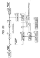
- FIG. 20 is a block diagram showing the configuration of a moving image coding apparatus equivalent to a seventh embodiment of the invention.
- the same reference number is allocated to the same part as that in the moving image coding apparatus equivalent to the first embodiment and shown in FIG. 1 and in the moving image coding apparatus equivalent to the sixth embodiment and shown in FIG. 13 .
- a reference number 2001 denotes a signal for inputting the motion information of the target from an external.
- FIGS. 21 to 25 are explanatory drawings for explaining moving image coding control in this embodiment.
- an image frame is configured by 30 macro blocks (lateral 6 pieces ⁇ vertical 5 pieces).
- a reference image memory 108 has capacity enough to record 18 reference image macro blocks.
- a target area to be intra-coded is a group of 12 macro blocks (macro block positions are 8 to 11 , 14 to 17 , 20 to 23 ) in the center and 18 reference image macro blocks in macro block positions to be inter-coded in the periphery of the target area are recorded into a reference image memory 108 as shown in a reference image 2103 .
- FIG. 22 is an explanatory drawing for explaining moving image coding control in the case it is judged based upon the motion information 2001 of a target input from an external in the coding of the (N ⁇ 1)th frame 2102 that the target shifts by one macro block upward.
- the target is predicted to shift as shown in 2201 showing a macro block position (a macro block address) in the Nth frame
- inter coding is instead performed for macro blocks in macro block positions 20 to 23 in the Nth frame 2202 and reference image macro blocks in the macro block positions 20 to 23 are recorded into recording space in which no reference image macro blocks in the macro block positions 2 to 5 are recorded into the reference image memory 108 .
- a numeral in the Nth frame 2202 denotes the transition of count values by an inter-macro block number counter 1301 in the coding of the (N ⁇ 1)th frame 2102 . It is known that control is made so that a count value is not negative.
- FIG. 23 is an explanatory drawing for explaining moving image coding control in the case it is judged based upon the motion information 2001 of a target input from an external that the target shifts by one macro block leftward in the coding of the (N ⁇ 1)th frame 2102 .
- the target is predicted to shift as like 2301 showing a macro block position (a macro block address) in the Nth frame
- intra coding is instead performed for macro blocks in macro block positions 7 , 13 , 19 in the Nth frame 2302 and reference image macro blocks in the macro block positions 7 , 13 , 19 are not recorded into the reference image memory 108 .
- inter coding is instead performed for macro blocks in macro block positions 11 , 17 , 23 in the Nth frame 2302 and reference image macro blocks in the macro block positions 11 , 17 , 23 are recorded into recording free space in which reference image macro blocks in the macro block positions 7 , 13 , 19 are not recorded into the reference image memory 108 .
- a numeral in the Nth frame 2302 denotes the transition of count values by the inter-macro block number counter 1301 in the coding of the (N ⁇ 1)th frame 2102 . In this case, it is also known that control is made so that a count value is not negative.
- FIG. 24 is an explanatory drawing for explaining moving image coding control in the case it is judged based upon the motion information 2001 of the target input from an external in the coding of the (N ⁇ 1)th frame 2102 that the target shifts by one macro block downward.
- the target is predicted to shift as like 2401 showing a macro block position (a macro block address) in the Nth frame
- intra coding is instead performed for macro blocks in macro block positions 1 to 6 outside the periphery of the target area in the Nth frame 2402 and reference image macro blocks in the macro block positions 1 to 6 are not recorded into the reference image memory 108 .
- inter coding is instead performed for macro blocks in macro block positions 8 to 11 in the Nth frame 2402 and reference image macro block in the macro block positions 8 to 11 are recorded into recording free space in which no reference image macro blocks in the macro block positions 1 to 6 are recorded into the reference image memory 108 .
- intra coding is instead performed for macro blocks in macro block positions 26 to 29 in the Nth frame 2402 and reference image macro blocks in the macro block positions 26 to 29 are not recorded into the reference image memory 108 .
- a numeral in the Nth frame 2302 denotes the transition of count values by the inter-macro block number counter 1301 in the coding of the (N ⁇ 1)th frame 2102 . In this case, it is also known that control is made so that a count value is not negative.
- FIG. 25 is an explanatory drawing for explaining moving image coding control in the case it is judged based upon the motion information 2001 of a target input from an external in the coding of the (N ⁇ 1)th frame 2102 that the target shifts by one macro block rightward.
- the target is predicted to shift in the Nth frame as like 2501 showing a macro block position (a macro block address)
- inter coding is instead performed for macro blocks in macro block positions 8 , 14 , 20 in the Nth frame 2502 and reference image macro blocks in the macro block positions 8 , 14 , 20 are recorded into recording free space in which no reference image macro blocks in the macro block positions 1 , 7 , 13 , 19 , 25 are recorded into the reference image memory 108 .
- intra coding is instead performed for macro blocks in macro block positions 12 , 18 , 24 in the Nth frame 2502 and no reference image macro blocks in the macro block positions 12 , 18 , 24 are recorded into the reference image memory 108 .
- a numeral in the Nth frame 2502 denotes the transition of count values by the inter-macro block number counter 1301 in the coding of the (N ⁇ 1)th frame 2102 . In this case, it is also known that control is made so that a count value is not negative.
- moving image coding that image quality is valued for a target to be photographed and coding efficiency is valued in the periphery of the target is enabled.
- Moving image coding when the target diagonally shifts is also enabled by executing coding in the combination of upward, downward, rightward and leftward four shift patterns described above.
- moving image coding according to prior art is performed for an image in image size within the capacity of a reference image memory, and for an image in image size larger than the capacity of the reference image memory, moving image coding the image size of which is free is enabled by limiting the number of maximum macro blocks for which inter coding is performed in one image frame and executing moving image coding using the same reference image memory.
- FIG. 26 is a block diagram showing the configuration of a moving image coding apparatus equivalent to an eighth embodiment of the invention.
- the same reference number is allocated to the same part as that in the moving image coding apparatus equivalent to the first embodiment and shown in FIG. 1 .
- a reference number 2601 denotes a signal for inputting image size information from an external to a memory controller 111 .
- FIG. 27 is an explanatory drawing for explaining moving image coding control in this embodiment.
- the embodiment for the moving image coding of a CIF image 2701 and the moving image coding of a VGA image 2703 using a reference image memory 108 which can record 400 reference image macro blocks is shown.
- the embodiment is an example for explanation and does not specify image size.
- inter coding can be performed for all macro blocks ( 396 pieces) of a CIF image 2701 in the case CIF image size is specified by image size information 2601 , conventional moving image coding in which the number of maximum macro blocks for which inter coding is performed in one image frame is not limited is executed.
- inter coding is performed for one per three macro blocks as shown in a VGA image frame 2704
- intra coding is performed for the other macro blocks
- moving image coding is enabled by recording only reference image macro blocks in macro block positions for which inter coding is performed in the next frame in the reference image memory 108 .
- moving image coding of plural image sizes using the same reference image memory is enabled by controlling the ratio of macro blocks for which inter coding is performed according to image size information.
- energy saving and processing efficiency are enhanced according to a situation of a photographed moving image by controlling so that the halt of a motion compensation function can be selected in addition to the above-mentioned method.
- FIG. 28 is a block diagram showing the configuration of the moving image coding apparatus equivalent to a ninth embodiment of the invention.
- the same reference number is allocated to the same part as that in the moving image coding apparatus equivalent to the first embodiment and shown in FIG. 1 .
- a motion compensation halt instruction signal 2801 input to a motion compensator 109 and a motion detector 110 is added to the configuration shown in FIG. 1 .
- the motion compensator 109 and the motion detector 110 halt the operation and in the case of inter coding, a reference image is directly provided as a predictive image based upon difference with a present image.
- the object of this embodiment is to record a frequency of past inter coding every macro block position as a history, to determine coding division every macro block position referring to the frequency when each setting is initialized in restarting and to improve image quality and coding efficiency.
- FIG. 29 is a block diagram showing the configuration of a moving image coding apparatus equivalent to a tenth embodiment of the invention.
- the same reference number is allocated to the same part as that in the moving image coding apparatus equivalent to the first embodiment and shown in FIG. 1 and in the moving image coding apparatus equivalent to the fourth embodiment and shown in FIG. 7 .
- an inter coding frequency counter 2901 is provided to count and record a frequency of past inter coding every macro block position.
- a memory controller 111 refers to the inter coding frequency counter 2901 when each setting is initialized in restarting and determines so that inter coding is previously performed for a macro block in a macro block position in which inter coding is more frequent in order.
- an image frame is configured by 30 macro blocks as shown in 2902 showing a macro block position (a macro block address) and 2903 shows a frequency of inter coding every macro block position recorded into the inter coding frequency counter 2901 .
- intra coding is performed for all macro blocks in a first frame after restarting.
- a frequency of inter coding 2903 every macro block position is referred and when the capacity of a reference image recording memory 108 is equivalent to a half of the capacity of an image frame, 15 macro blocks in macro block positions in which inter coding is more frequent are selected and the macro block positions for which inter coding is performed are determined.
- image quality and coding efficiency in frames subsequent to the second frame immediately after activation can be improved.
- This method is particularly effective in the fixed outside monitoring camera, however, in a moving camera such as a mobile telephone provided with a camera, the effect of this method cannot be expected because the change of temporal correlation of an image is large. Therefore, it is desirable that the moving image coding apparatus is provided with a function for selecting whether this function is to be made effective or not and whether a frequency of inter coding is to be stored or not.
- reference images of all macro blocks in a current frame are not required to be prepared by determining macro block positions for which intra coding or inter coding is performed in the coding of an image prior to the present image, the capacity of the reference image memory can be reduced and the cost of the moving image coding apparatus can be reduced.
Abstract
Description
Claims (43)
Applications Claiming Priority (2)
| Application Number | Priority Date | Filing Date | Title |
|---|---|---|---|
| JPP2003-057199 | 2003-03-04 | ||
| JP2003057199A JP3934568B2 (en) | 2003-03-04 | 2003-03-04 | Video coding method and apparatus |
Publications (2)
| Publication Number | Publication Date |
|---|---|
| US20040175049A1 US20040175049A1 (en) | 2004-09-09 |
| US7257262B2 true US7257262B2 (en) | 2007-08-14 |
Family
ID=32923536
Family Applications (1)
| Application Number | Title | Priority Date | Filing Date |
|---|---|---|---|
| US10/644,854 Expired - Fee Related US7257262B2 (en) | 2003-03-04 | 2003-08-21 | Moving image coding method and apparatus for determining a position of a macro block which is intra-coded or inter-coded |
Country Status (3)
| Country | Link |
|---|---|
| US (1) | US7257262B2 (en) |
| JP (1) | JP3934568B2 (en) |
| CN (1) | CN1257650C (en) |
Cited By (4)
| Publication number | Priority date | Publication date | Assignee | Title |
|---|---|---|---|---|
| US20050201627A1 (en) * | 2004-03-11 | 2005-09-15 | Yi Liang | Methods and apparatus for performing fast mode decisions in video codecs |
| US20090245663A1 (en) * | 2008-03-28 | 2009-10-01 | Fujitsu Limited | Image data decoding apparatus and method for decoding image data |
| US9371099B2 (en) | 2004-11-03 | 2016-06-21 | The Wilfred J. and Louisette G. Lagassey Irrevocable Trust | Modular intelligent transportation system |
| US11102475B2 (en) | 2018-12-18 | 2021-08-24 | Renesas Electronics Corporation | Video encoding device, operating methods thereof, and vehicles equipped with a video encoding device |
Families Citing this family (21)
| Publication number | Priority date | Publication date | Assignee | Title |
|---|---|---|---|---|
| EP1759532A1 (en) * | 2004-06-11 | 2007-03-07 | Koninklijke Philips Electronics N.V. | Method of storing pictures in a memory using compression coding and cost function including power consumption |
| JP2006121415A (en) * | 2004-10-21 | 2006-05-11 | Olympus Corp | Moving image encoding device |
| JP2006237970A (en) * | 2005-02-24 | 2006-09-07 | Mitsubishi Electric Corp | Motion picture coding device |
| EP1994756A2 (en) * | 2006-03-03 | 2008-11-26 | Koninklijke Philips Electronics N.V. | Differential coding with lossy embedded compression |
| CN101411200B (en) * | 2006-04-03 | 2011-08-10 | 英国电讯有限公司 | Method of video signal coding |
| JP4712643B2 (en) | 2006-08-17 | 2011-06-29 | 富士通セミコンダクター株式会社 | Inter-frame prediction processing apparatus, inter-frame prediction method, image encoding apparatus, and image decoding apparatus |
| JP4763549B2 (en) | 2006-08-18 | 2011-08-31 | 富士通セミコンダクター株式会社 | Inter-frame prediction processing apparatus, image encoding apparatus, and image decoding apparatus |
| EP2512139B1 (en) * | 2006-10-30 | 2013-09-11 | Nippon Telegraph And Telephone Corporation | Video encoding method and decoding method, apparatuses therefor, programs therefor, and storage media which store the programs |
| JP2010103969A (en) * | 2008-09-25 | 2010-05-06 | Renesas Technology Corp | Image-decoding method, image decoder, image encoding method, and image encoder |
| JP2013110466A (en) * | 2011-11-17 | 2013-06-06 | Hitachi Kokusai Electric Inc | Moving image encoding device |
| EP2814253B1 (en) * | 2013-06-05 | 2015-09-16 | Axis AB | Method for encoding digital video data |
| JP6468703B2 (en) * | 2013-12-20 | 2019-02-13 | キヤノン株式会社 | Motion detection device, motion detection method, and program |
| JP2015173404A (en) * | 2014-03-12 | 2015-10-01 | 富士通株式会社 | Video image encoding device, video image encoding method, and video image encoding computer program |
| US10104397B2 (en) | 2014-05-28 | 2018-10-16 | Mediatek Inc. | Video processing apparatus for storing partial reconstructed pixel data in storage device for use in intra prediction and related video processing method |
| JP6335711B2 (en) * | 2014-08-05 | 2018-05-30 | セイコーエプソン株式会社 | Tape printer |
| JP6453652B2 (en) * | 2015-01-09 | 2019-01-16 | 株式会社東芝 | Video transmission system |
| WO2017037502A1 (en) * | 2015-08-29 | 2017-03-09 | Chan Kam Fu | Compression code and method by location |
| CN108401158B (en) * | 2017-02-07 | 2021-01-22 | 深圳市中兴微电子技术有限公司 | Context adaptive binary arithmetic coding renormalization realization method and device |
| JP7359653B2 (en) | 2019-11-06 | 2023-10-11 | ルネサスエレクトロニクス株式会社 | Video encoding device |
| CN111447451A (en) * | 2020-03-23 | 2020-07-24 | 西安万像电子科技有限公司 | Image coding and decoding method and device |
| US11625938B2 (en) * | 2020-12-29 | 2023-04-11 | Industrial Technology Research Institute | Method and device for detecting human skeletons |
Citations (14)
| Publication number | Priority date | Publication date | Assignee | Title |
|---|---|---|---|---|
| JPH0837663A (en) | 1994-07-22 | 1996-02-06 | Canon Inc | Encoder |
| US5870500A (en) * | 1995-12-06 | 1999-02-09 | Thomson Multimedia S.A. | Method for processing data in matrix arrays in a motion estimation system |
| JPH11313327A (en) | 1998-04-28 | 1999-11-09 | Hitachi Ltd | Motion compensation device |
| US6115070A (en) | 1997-06-12 | 2000-09-05 | International Business Machines Corporation | System and method for DCT domain inverse motion compensation using shared information |
| US6118818A (en) | 1996-04-09 | 2000-09-12 | Lg Electronics, Inc. | Method for decoding MPEG standard video bit stream |
| US6134269A (en) * | 1996-09-25 | 2000-10-17 | At&T Corp | Fixed or adaptive deinterleaved transform coding for image coding and intra coding of video |
| US6192078B1 (en) * | 1997-02-28 | 2001-02-20 | Matsushita Electric Industrial Co., Ltd. | Motion picture converting apparatus |
| JP2001186523A (en) | 1999-12-22 | 2001-07-06 | Canon Inc | Image-processing unit and its method and storage medium |
| US6370276B2 (en) * | 1997-04-09 | 2002-04-09 | Matsushita Electric Industrial Co., Ltd. | Image predictive decoding method, image predictive decoding apparatus, image predictive coding method, image predictive coding apparatus, and data storage media |
| JP2002112270A (en) | 2000-09-27 | 2002-04-12 | Nec Corp | Moving picture high-speed encoder and moving picture high-speed encoding method |
| US20020176498A1 (en) | 2001-05-24 | 2002-11-28 | Per Frojdh | Selective prediction for intra-coding video data block |
| US6542545B1 (en) * | 1999-10-01 | 2003-04-01 | Mitsubishi Electric Reseach Laboratories, Inc. | Estimating rate-distortion characteristics of binary shape data |
| US6782132B1 (en) * | 1998-08-12 | 2004-08-24 | Pixonics, Inc. | Video coding and reconstruction apparatus and methods |
| US7116831B2 (en) * | 2002-04-10 | 2006-10-03 | Microsoft Corporation | Chrominance motion vector rounding |
-
2003
- 2003-03-04 JP JP2003057199A patent/JP3934568B2/en not_active Expired - Fee Related
- 2003-08-21 US US10/644,854 patent/US7257262B2/en not_active Expired - Fee Related
- 2003-09-19 CN CNB031573401A patent/CN1257650C/en not_active Expired - Fee Related
Patent Citations (14)
| Publication number | Priority date | Publication date | Assignee | Title |
|---|---|---|---|---|
| JPH0837663A (en) | 1994-07-22 | 1996-02-06 | Canon Inc | Encoder |
| US5870500A (en) * | 1995-12-06 | 1999-02-09 | Thomson Multimedia S.A. | Method for processing data in matrix arrays in a motion estimation system |
| US6118818A (en) | 1996-04-09 | 2000-09-12 | Lg Electronics, Inc. | Method for decoding MPEG standard video bit stream |
| US6134269A (en) * | 1996-09-25 | 2000-10-17 | At&T Corp | Fixed or adaptive deinterleaved transform coding for image coding and intra coding of video |
| US6192078B1 (en) * | 1997-02-28 | 2001-02-20 | Matsushita Electric Industrial Co., Ltd. | Motion picture converting apparatus |
| US6370276B2 (en) * | 1997-04-09 | 2002-04-09 | Matsushita Electric Industrial Co., Ltd. | Image predictive decoding method, image predictive decoding apparatus, image predictive coding method, image predictive coding apparatus, and data storage media |
| US6115070A (en) | 1997-06-12 | 2000-09-05 | International Business Machines Corporation | System and method for DCT domain inverse motion compensation using shared information |
| JPH11313327A (en) | 1998-04-28 | 1999-11-09 | Hitachi Ltd | Motion compensation device |
| US6782132B1 (en) * | 1998-08-12 | 2004-08-24 | Pixonics, Inc. | Video coding and reconstruction apparatus and methods |
| US6542545B1 (en) * | 1999-10-01 | 2003-04-01 | Mitsubishi Electric Reseach Laboratories, Inc. | Estimating rate-distortion characteristics of binary shape data |
| JP2001186523A (en) | 1999-12-22 | 2001-07-06 | Canon Inc | Image-processing unit and its method and storage medium |
| JP2002112270A (en) | 2000-09-27 | 2002-04-12 | Nec Corp | Moving picture high-speed encoder and moving picture high-speed encoding method |
| US20020176498A1 (en) | 2001-05-24 | 2002-11-28 | Per Frojdh | Selective prediction for intra-coding video data block |
| US7116831B2 (en) * | 2002-04-10 | 2006-10-03 | Microsoft Corporation | Chrominance motion vector rounding |
Cited By (8)
| Publication number | Priority date | Publication date | Assignee | Title |
|---|---|---|---|---|
| US20050201627A1 (en) * | 2004-03-11 | 2005-09-15 | Yi Liang | Methods and apparatus for performing fast mode decisions in video codecs |
| US7881386B2 (en) * | 2004-03-11 | 2011-02-01 | Qualcomm Incorporated | Methods and apparatus for performing fast mode decisions in video codecs |
| US9371099B2 (en) | 2004-11-03 | 2016-06-21 | The Wilfred J. and Louisette G. Lagassey Irrevocable Trust | Modular intelligent transportation system |
| US10979959B2 (en) | 2004-11-03 | 2021-04-13 | The Wilfred J. and Louisette G. Lagassey Irrevocable Trust | Modular intelligent transportation system |
| US20090245663A1 (en) * | 2008-03-28 | 2009-10-01 | Fujitsu Limited | Image data decoding apparatus and method for decoding image data |
| US8249373B2 (en) | 2008-03-28 | 2012-08-21 | Fujistu Limited | Image data decoding apparatus and method for decoding image data |
| US11102475B2 (en) | 2018-12-18 | 2021-08-24 | Renesas Electronics Corporation | Video encoding device, operating methods thereof, and vehicles equipped with a video encoding device |
| US11606552B2 (en) | 2018-12-18 | 2023-03-14 | Renesas Electronics Corporation | Video encoding device, operating methods thereof, and vehicles equipped with a video encoding device |
Also Published As
| Publication number | Publication date |
|---|---|
| CN1527611A (en) | 2004-09-08 |
| JP3934568B2 (en) | 2007-06-20 |
| CN1257650C (en) | 2006-05-24 |
| US20040175049A1 (en) | 2004-09-09 |
| JP2004266731A (en) | 2004-09-24 |
Similar Documents
| Publication | Publication Date | Title |
|---|---|---|
| US7257262B2 (en) | Moving image coding method and apparatus for determining a position of a macro block which is intra-coded or inter-coded | |
| US10375401B2 (en) | Moving picture coding method, moving picture decoding method, and apparatuses of the same | |
| CN110740318A (en) | Automatic adaptive long-term reference frame selection for video processing and video coding | |
| US7916785B2 (en) | Image processing apparatus and method | |
| US20170318295A1 (en) | Method for implementing a quantizer in a multimedia compression and encoding system | |
| US20040218675A1 (en) | Method and apparatus for determining reference picture and block mode for fast motion estimation | |
| KR100843418B1 (en) | Apparatus and method for image coding | |
| US20060140275A1 (en) | Motion vector operation devices and methods including prediction | |
| US10284850B2 (en) | Method and system to control bit rate in video encoding | |
| JP4217174B2 (en) | Moving picture coding apparatus and moving picture coding method | |
| US20080031335A1 (en) | Motion Detection Device | |
| KR100360005B1 (en) | Image processor and image processing method | |
| US20160261869A1 (en) | Content-adaptive b-picture pattern video encoding | |
| US20070237220A1 (en) | Systems and methods for changing rate-control setting during video encoding | |
| US7751474B2 (en) | Image encoding device and image encoding method | |
| JPH11308617A (en) | Digital image coder and motion vector detector used therefor | |
| US20080298769A1 (en) | Method and system for generating compressed video to improve reverse playback | |
| CN100548052C (en) | Dynamic image encoding method and equipment | |
| JP2003102007A (en) | Signal processing apparatus | |
| JP4594214B2 (en) | Image decoding device | |
| JP2008072608A (en) | Apparatus and method for encoding image | |
| JP3744018B2 (en) | Block image shift device and image decoder | |
| JPH01103387A (en) | Compression device for picture data by prediction coding | |
| JP3013090B2 (en) | Quantization control method | |
| US8345992B2 (en) | Method and device of image encoding and image processing apparatus |
Legal Events
| Date | Code | Title | Description |
|---|---|---|---|
| AS | Assignment |
Owner name: MATSUSHITA ELECTRIC INDUSTRIAL CO., LTD., JAPAN Free format text: ASSIGNMENT OF ASSIGNORS INTEREST;ASSIGNORS:YAMAMOTO, TAKAHIRO;NAKAHARA, MITSUYA;INOKUMA, KAZUYUKI;AND OTHERS;REEL/FRAME:014425/0372 Effective date: 20030801 |
|
| STCF | Information on status: patent grant |
Free format text: PATENTED CASE |
|
| FEPP | Fee payment procedure |
Free format text: PAYOR NUMBER ASSIGNED (ORIGINAL EVENT CODE: ASPN); ENTITY STATUS OF PATENT OWNER: LARGE ENTITY |
|
| FPAY | Fee payment |
Year of fee payment: 4 |
|
| AS | Assignment |
Owner name: PANASONIC CORPORATION, JAPAN Free format text: CHANGE OF NAME;ASSIGNOR:MATSUSHITA ELECTRIC INDUSTRIAL CO., LTD.;REEL/FRAME:031947/0358 Effective date: 20081001 |
|
| AS | Assignment |
Owner name: PANASONIC CORPORATION, JAPAN Free format text: LIEN;ASSIGNOR:COLLABO INNOVATIONS, INC.;REEL/FRAME:031997/0445 Effective date: 20131213 |
|
| AS | Assignment |
Owner name: COLLABO INNOVATIONS, INC., CANADA Free format text: ASSIGNMENT OF ASSIGNORS INTEREST;ASSIGNOR:PANASONIC CORPORATION;REEL/FRAME:033021/0806 Effective date: 20131212 |
|
| FPAY | Fee payment |
Year of fee payment: 8 |
|
| FEPP | Fee payment procedure |
Free format text: MAINTENANCE FEE REMINDER MAILED (ORIGINAL EVENT CODE: REM.); ENTITY STATUS OF PATENT OWNER: LARGE ENTITY |
|
| LAPS | Lapse for failure to pay maintenance fees |
Free format text: PATENT EXPIRED FOR FAILURE TO PAY MAINTENANCE FEES (ORIGINAL EVENT CODE: EXP.); ENTITY STATUS OF PATENT OWNER: LARGE ENTITY |
|
| STCH | Information on status: patent discontinuation |
Free format text: PATENT EXPIRED DUE TO NONPAYMENT OF MAINTENANCE FEES UNDER 37 CFR 1.362 |
|
| FP | Lapsed due to failure to pay maintenance fee |
Effective date: 20190814 |