US7259693B2 - Air vessel tracking system and method - Google Patents
Air vessel tracking system and method Download PDFInfo
- Publication number
- US7259693B2 US7259693B2 US10/823,988 US82398804A US7259693B2 US 7259693 B2 US7259693 B2 US 7259693B2 US 82398804 A US82398804 A US 82398804A US 7259693 B2 US7259693 B2 US 7259693B2
- Authority
- US
- United States
- Prior art keywords
- aircraft
- flight characteristics
- normal
- alert
- flight
- Prior art date
- Legal status (The legal status is an assumption and is not a legal conclusion. Google has not performed a legal analysis and makes no representation as to the accuracy of the status listed.)
- Active, expires
Links
Images


Classifications
-
- G—PHYSICS
- G08—SIGNALLING
- G08G—TRAFFIC CONTROL SYSTEMS
- G08G5/00—Traffic control systems for aircraft, e.g. air-traffic control [ATC]
- G08G5/0073—Surveillance aids
- G08G5/0078—Surveillance aids for monitoring traffic from the aircraft
-
- G—PHYSICS
- G08—SIGNALLING
- G08G—TRAFFIC CONTROL SYSTEMS
- G08G5/00—Traffic control systems for aircraft, e.g. air-traffic control [ATC]
- G08G5/0047—Navigation or guidance aids for a single aircraft
- G08G5/006—Navigation or guidance aids for a single aircraft in accordance with predefined flight zones, e.g. to avoid prohibited zones
Definitions
- This invention relates generally to methods for detecting and reporting the state of a vessel during travel.
- An embodiment of the invention may be used detect and report the in-flight state of an air vessel.
- a marine vessel tracking system is a system that uses reports transmitted from marine vessels to a tracking center to follow marine traffic, described in U.S. Pat. No. 6,658,349 to Cline, which is incorporated by reference as if fully set forth herein.
- Another example of such a system was developed as a government-off-the-shelf (GOTS) vessel tracking system for the U.S. Coast Guard by the Naval Air Warfare Center, Aircraft Division (NAWCAD) at Paxutent River, Maryland. This system is generally known as the Coast Guard Vessel Traffic System (CGVTS).
- GOTS government-off-the-shelf
- the CGVTS replaced radar plan position indicator (PPI) displays with commercial computer systems able to present radar images and tracks overlaid on electronic charts.
- the CGVTS may be integrated with a set of closed-circuit television (CCTV) cameras and/or voice radio communication interfaces to provide a more complete vessel traffic management system.
- CCTV closed-circuit television
- the CGVTS system was installed successfully in the ports of New York, Puget Sound, and San Francisco harbors between 1993 and 1995.
- the original CGVTS system was designed to run on a UNIX operating system. Following introduction of the original CGVTS, code for operating the CGVTS has been ported to Microsoft Windows® operating systems (e.g., Windows® NT and Windows® 2000). The CGVTS may be operated on commercial-off-the-shelf (COTS) systems on the Microsoft Windows® operating system.
- COTS commercial-off-the-shelf
- the system has been updated, refined, and renamed SureTrakTM by NAWCAD.
- Current versions of the SureTrakTM vessel tracking system include several functional components (e.g., sensors, data analysis components, tracking components).
- the SureTrakTM vessel tracking system includes a system architecture that allows functional components to operate on separate processors or allows functional components to be co-located on a single processor. Such a system architecture allows the vessel tracking system to be flexible in size and allows for integration of new or updated functional components more easily.
- a vessel tracking system may be used to detect and report an alert condition of a vessel (e.g., an aircraft).
- the vessel tracking system may monitor one or more travel characteristics (e.g., flight characteristics) of the vessel. At least one of the travel characteristics may be compared to one or more normal travel characteristics to assess (e.g., determine) an alert condition of the vessel.
- the alert condition of the vessel may be reported (e.g., visually reported on a display).
- An alert condition of the vessel may include an alert level for the vessel that corresponds to a danger level or threat level for the vessel based on the vessel's travel characteristics.
- a vessel tracking system may assess (e.g., determine) a dynamic state of a vessel from one or more travel characteristics of the vessel.
- the dynamic state of the vessel may be compared to a normal dynamic state for the vessel. If at least one travel characteristic of the dynamic state of the vessel deviates from a predetermined value of at least one normal travel characteristic of the normal dynamic state, a boundary condition of an alert for the vessel may be modified (e.g., increased).
- An alert for the vessel may include, but is not limited to, a proximity alert, a boundary alert, and/or an exclusive area alert. An alarm may be provided when at least one boundary condition of the alert is crossed.
- one or more normal travel characteristics of a vessel may be modified based on a flight phase of the vessel.
- a flight phase of the vessel may include, but is not limited to, takeoff, enroute, approach, and landing.
- one or more of the travel characteristics of a vessel may be modified if at least one travel characteristic of the vessel deviates from a predetermined value of at least one normal travel characteristic of the vessel.
- FIG. 1 illustrates an embodiment of a wide area network (“WAN”) for use with various tracking system embodiments.
- WAN wide area network
- FIG. 2 illustrates an embodiment of computer system that may be suitable for implementing various tracking system embodiments.
- FIG. 3 depicts an example of a display of a track of an aircraft.
- FIG. 4 depicts an example of a normal proximity alert volume for an aircraft.
- FIG. 5 depicts an example of a normal area boundary for an aircraft.
- FIG. 6 depicts an example of a normal exclusive area for an aircraft.
- FIG. 7 depicts an example of a display of a vessel track and an alert window.
- FIG. 8A depicts a flowchart for an embodiment for tracking a vessel.
- FIG. 8 depicts an example of a proximity alert volume for an aircraft with an increased vertical area.
- FIG. 9 depicts an example of a proximity alert volume for an aircraft with an increased horizontal area.
- FIG. 10 depicts an example of a proximity alert volume for an aircraft with increased vertical area and an increased horizontal area.
- FIG. 12 depicts maximum vertical proximity alert volume extent and maximum vertical look ahead travel along with vertical velocity in an example.
- FIG. 13 depicts maximum horizontal proximity alert volume extent and maximum horizontal look ahead travel versus horizontal velocity in an example.
- a computer system may acquire data from one or more sensing systems.
- One or more computer systems and one or more sensing systems may be linked over a wide area network (“WAN”).
- Data from sensing systems may be transferred to one or more computer systems in real-time or in near real-time.
- data may be acquired from one or more sensing systems at a primary location (e.g., a primary computer system or computer mainframe server) and then distributed to one or more clients (e.g., computer workstations or personal computers).
- FIG. 1 illustrates an embodiment of a WAN.
- WAN 102 may be a network that spans a relatively large geographical area.
- the Internet is an example of WAN 102 .
- WAN 102 typically includes a plurality of computer systems that may be interconnected through one or more networks. Although one particular configuration is shown in FIG. 1 , WAN 102 may include a variety of heterogeneous computer systems and networks that may be interconnected in a variety of ways and that may run a variety of software applications.
- LAN 104 may be coupled to WAN 102 .
- LAN 104 may be a network that spans a relatively small area. Typically, LAN 104 may be confined to a single building or group of buildings.
- Each node (i.e., individual computer system or device) on LAN 104 may have its own CPU with which it may execute programs, and each node may also be able to access data and devices anywhere on LAN 104 .
- LAN 104 may allow many users to share devices (e.g., printers) and data stored on file servers.
- LAN 104 may include a plurality of interconnected clients and servers.
- each LAN 104 may include a plurality of interconnected computer systems and optionally one or more other devices such as one or more workstations 110 a, one or more personal computers 112 a, one or more laptop or notebook computer systems 114 , one or more server computer systems 116 , one or more network printers 118 , and one or more sensing systems 119 a.
- an example LAN 104 may include one of each of computer systems 110 a, 112 a, 114 , and 116 and one printer 118 .
- LAN 104 may be coupled to other computer systems and/or other devices and/or other LANs 104 through WAN 102 .
- mainframe computer systems 120 may be coupled to WAN 102 .
- mainframe 120 may be coupled to a storage device or file server 124 and mainframe terminals 122 a, 122 b, and 122 c.
- Mainframe terminals 122 a, 122 b, and 122 c may access data stored in the storage device or file server 124 coupled to or included in mainframe computer system 120 .
- WAN 102 may also include computer systems connected to WAN 102 individually and not through LAN 104 (e.g., workstation 110 b, personal computer 112 b, and sensing system 119 b ).
- WAN 102 may include computer systems or sensing systems that may be geographically remote and connected to each other through the Internet (e.g., using TCP-IP (transmission control protocol over internet protocol) connectivity and/or a client-server environment).
- TCP-IP transmission control protocol over internet protocol
- FIG. 2 illustrates an embodiment of computer system 250 that may be suitable for implementing various embodiments of a system and method for tracking vessels.
- Each computer system 250 typically includes components such as CPU 252 with an associated memory medium such as floppy disks 260 .
- the memory medium may store program instructions for computer programs.
- the program instructions may be executable by CPU 252 .
- Computer system 250 may further include a display device such as monitor 254 , an alphanumeric input device such as keyboard 256 , and a directional input device such as mouse 258 .
- Computer system 250 may be operable to execute the computer programs to implement computer-implemented systems and methods for tracking vessels.
- Computer system 250 may include a memory medium on which computer programs according to various embodiments may be stored.
- the term “memory medium” is intended to include an installation medium, e.g., a CD-ROM or floppy disks 260 , a computer system memory such as DRAM, SRAM, EDO RAM, Rambus RAM, etc., or a non-volatile memory such as a magnetic media, e.g., a hard drive or optical storage.
- the memory medium may also include other types of memory or combinations thereof.
- the memory medium may be located in a first computer, which executes the programs or may be located in a second different computer, which connects to the first computer over a network. In the latter instance, the second computer may provide the program instructions to the first computer for execution.
- Computer system 250 may take various forms such as a personal computer system, mainframe computer system, workstation, network appliance, Internet appliance, personal digital assistant (“PDA”), television system or other device.
- PDA personal digital assistant
- computer system may refer to any device having a processor that executes instructions from a memory medium.
- the memory medium may store a software program or programs operable to implement a method for tracking vessels.
- the software program(s) may be implemented in various ways, including, but not limited to, procedure-based techniques, component-based techniques, and/or object-oriented techniques, among others.
- the software programs may be implemented using ActiveX controls, C++ objects, JavaBeans, Microsoft Foundation Classes (“MFC”), browser-based applications (e.g., Java applets), traditional programs, or other technologies or methodologies, as desired.
- a CPU such as host CPU 252 executing code and data from the memory medium may include a means for creating and executing the software program or programs according to the embodiments described herein.
- a vessel tracking system may track and/or manage one or more vessels.
- a vessel tracking system used to track and manage vessels is SureTrakTM available from NAWCAD.
- SureTrakTM is a government-off-the-shelf (GOTS) system that uses multiple sensors, fully integrated data acquisition, and a display system to receive, integrate, and display data from a variety of remote sensing systems.
- SureTrakTM may be run on commercial-off-the-shelf (COTS) computer systems and/or computer workstations.
- COTS commercial-off-the-shelf
- SureTrakTM may operate on a Microsoft Windows® based computer system.
- a vessel tracking system may include one or more functional components (e.g., sensors or sensing systems).
- Functional components may include, but are not limited to, an operator display system (ODS), a sensor data system (SDS), and a data base system (DBS).
- ODS operator display system
- SDS sensor data system
- DBS data base system
- the functional components of the vessel tracking system may be integrated in a modular design.
- each functional component may operate on a separate computer processor.
- functional components may be co-located on a single computer processor. Integrating the functional components in a modular design allows a vessel tracking system to flexibly operate as either a small system with a few sensors or a relatively large system with many sensors.
- a modular design may also allow for easier integration of new functional components (e.g., new sensors or new sensor types) into a vessel tracking system.
- the modular designed vessel tracking system may also be modified to meet specific requirements required by an individual end user.
- a vessel tracking system may track one or more vessels.
- the vessels may be marine vessels (e.g., boats, ships, submarines), land vessels (e.g., trains, automobiles, trucks), and/or air vessels (e.g., airplanes, helicopters, missiles).
- a vessel tracking system may integrate data from one or more sensing systems to provide an integrated track of a vessel.
- a vessel tracking system may integrate data with varying data formats. Some examples of data formats may include, but are not limited to, CD2 (common digitizer protocol), Asterix (All-purpose Structured Radar Information Exchange), Link 11 (tactical data information link), and GPS.
- a vessel tracking system may simultaneously track more than one vessel.
- a vessel tracking system may simultaneously track marine, land, and/or air vessels.
- a vessel tracking system may provide a visual representation of the vessel track.
- a vessel tracking system may visually display the vessel track on one or more display devices (e.g., a computer monitor or other visual display device).
- a vessel tracking system may visually display more than one track on an output display.
- a vessel tracking system may visually display tracks of two or more vessels or may visually display tracks of a single vessel acquired from two or more sensing systems (i.e., display multiple tracks of a single vessel rather than an integrated track of the single vessel).
- FIG. 3 depicts an example of a display of a track of a vessel.
- Display 300 may be a functional component of a vessel tracking system.
- display 300 is a map display.
- Vessel 302 may be displayed on display 300 .
- Display 300 may also display one or more other identifiable features.
- display 300 may display geographic features 304 , other vessels 306 , and/or boundary information 308 .
- Display 300 may also identify locations of other miscellaneous features such as, but not limited to, man-made objects, roads, and sensing system locations.
- Display 300 may include alert condition level 310 of vessel 302 .
- Alert condition level 310 may identify the alert condition of vessel 302 .
- Alert condition level 310 may identify the alert condition of vessel 302 to a user (e.g., an air traffic controller or other monitoring personnel).
- alert condition level 310 may be a level indicator (e.g., a bar level indicator).
- Alert condition level 310 may include color-coded identification of the alert level (e.g., red for a high alert condition, green for a low alert condition, etc.).
- alert condition level 310 may be coupled with an audible alarm that alerts a user to a change in the alert condition of vessel 302 (e.g., an audible warning alarm for a high alert condition).
- Display 300 may include other advanced display features as required by a user of a vessel tracking system.
- a vessel tracking system functional component may include an algorithm that displays a most recent vessel track update from a highest quality sensor or sensing system.
- the algorithm may be a track correlation processing (TCP) algorithm.
- the algorithm may be a fuzzy logic algorithm.
- An algorithm may assign each sensor a priority value within a hierarchy of sensors.
- the algorithm may display a most recent vessel track update from the sensor having the highest priority in the hierarchy of sensors.
- certain sensors e.g., telemetry tracking radars or Passive Coherent Location (PCL) systems
- PCL Passive Coherent Location
- An algorithm may correlate vessel tracks from “position only” systems with vessel tracks from vessel identifying systems (e.g., ASR-8, ASR-9, DASR-11).
- the algorithm may use vessel course, speed, and/or altitude information to correlate the vessel tracks. Correlating the vessel tracks may allow for rapid updating of vessel track information using a “position only” system while maintaining the identification of the vessel.
- a vessel tracking system functional component may include a surface surveillance module.
- a surface surveillance module may include surface radar (e.g., a PC-RP 201 (PC based radar processor)) used to enhance track discrimination for vessels with relatively small radar cross sections.
- a surface surveillance module may include Furuno type surface radars. Furuno type surface radars may be used to track low-level air targets.
- a surface surveillance module may be combined with other modules to provide enhanced vessel tracking.
- a vessel tracking system functional component may include a multi-static dependent surveillance (MDS) system.
- MDS multi-static dependent surveillance
- An embodiment of an MDS system may be obtained from Sensis Co. (DeWitt, N.Y.).
- An MDS system may provide relatively fast update rates (e.g., about 1 second) and high accuracy (e.g., about 10 m to about 40 m). Fast update rates and high accuracies may be useful for monitoring of high dynamic activities of a vessel. For example, high dynamic activities of an air vessel may be monitored in research, development, test, and evaluation (RDT&E) missions.
- RDT&E research, development, test, and evaluation
- an MDS system may allow for substantially immediate notification of deviations in the flight characteristics of an air vessel (e.g., an aircraft on final approach).
- a vessel tracking system functional component may include an integrated camera system (ICS).
- ICS has been used for marine vessel applications.
- ICS may be used to identify low-level air vessels (e.g., low-level air vessels that are non-cooperative).
- Non-cooperative air vessels may include, for example, air vessels that do not respond to air traffic controller interrogation or display an Identification, Friend or Foe (IFF) signal.
- An ICS may include one or more camera systems. Camera systems may include, but are not limited to, daylight, thermal, short range, or long range camera systems.
- a camera in an ICS system may be programmed to track a single vessel.
- a vessel tracking system may identify a vessel in a high alert condition (e.g., the vessel may enter into an exclusive area or may cross an alert boundary).
- the vessel tracking system may program a camera to track the high alert condition vessel.
- an operator may visually identify the high alert condition vessel and assess (e.g., determine) if further action is needed in dealing with the vessel (e.g., the vessel may be identified as releasing a chemical or biological agent).
- a camera may be automatically slaved to track a vessel once the vessel is identified as a high alert condition vessel.
- a vessel tracking system functional component may include a passive coherent location (PCL) system.
- PCL systems include CELLDARTM from Roke Manor Research Limited (United Kingdom) and Silent Sentry® from Lockheed-Martin Mission Systems (Gaithersburg, Md.). PCL systems may provide relatively inexpensive, all weather, passive detection and tracking of vessels.
- a vessel tracking system functional component may include an automated decision support (ADS) component.
- An ADS component may include algorithms for providing alerts for tracked vessels. Alerts may include, but are not limited to, proximity alerts, boundary alerts, and exclusive area alerts. An alarm may be provided if a vessel crosses a boundary condition of an alert. Different alarms (e.g., visual or audio alarms) may be provided for different types of alerts.
- Boundary conditions e.g., distances from a vessel
- Boundary conditions may be defined in either 2 dimensions (2-D) or 3 dimensions (3-D) around a vessel. Boundary conditions may be defined automatically by a vessel tracking system or defined by a user of a vessel tracking system.
- boundary conditions may be modified based on an alert condition of a vessel. In certain embodiments, boundary conditions may be modified based on a transportation phase of a vessel (e.g., a flight phase of an air vessel).
- a proximity alert may include an alert when two or more vessels approach within a selected distance of each other (e.g., a selected horizontal (radial) distance or a selected vertical distance (altitude)).
- a proximity alert may include a visual alarm and/or an audio alarm.
- a visual alarm may be provided on a display (e.g., display 300 shown in FIG. 3 ).
- the boundary conditions of a proximity alert may be defined by a user of a vessel tracking system.
- a proximity alert may be applied only to selected vessel tracks. Vessel tracks having a proximity alert may be selected by a user of a vessel tracking system or may be automatically selected by the vessel tracking system based on, for example, a flight phase of a vessel or a location of a vessel.
- FIG. 4 depicts an example of a normal proximity alert volume for an aircraft.
- Vessel 302 has normal proximity alert volume 320 .
- vessel 302 may be an aircraft.
- the boundary conditions of normal proximity alert volume 320 may be defined by vertical separation distance 322 and horizontal separation distance 324 .
- vertical separation distance 322 may be the same above and below vessel 302 .
- vertical separation distance 322 may vary above and below vessel 302 .
- Typical vertical separation distances 322 for an aircraft may be, for example, about 1000 feet, about 2000 feet, about 3000 feet, about 4000 feet, or about 5000 feet.
- Typical horizontal separation distances 324 for an aircraft may be, for example, about 3 nautical miles, about 4 nautical miles, about 5 nautical miles, or about 6 nautical miles.
- the separation distances may vary, for example, based on a type of vessel 302 (e.g., military or civilian aircraft). Separation distances may be defined by a user of a vessel tracking system. An alarm may be activated when another vessel enters normal proximity alert volume 320 .
- a boundary alert may include an alert when a vessel approaches within a selected distance of an area boundary.
- An area boundary may be defined in horizontal and/or vertical space.
- An area boundary may define an area or volume in which a vessel is restricted from traveling (e.g., a “no-fly” zone).
- Boundary conditions of an area boundary may be defined on a map or other geographic template. Boundary conditions of an area boundary may be predetermined according to a type of area. In an embodiment, boundary conditions of an area boundary are defined by a user of a vessel tracking system.
- a boundary alert may include a visual alarm and/or an audio alarm.
- FIG. 5 depicts an example of a normal area boundary for an aircraft.
- Vessel 302 may approach normal area boundary 330 .
- Normal area boundary 330 may be a 2-D area or a 3-D volume.
- Boundary conditions for normal area boundary 330 may include horizontal area and/or vertical area.
- normal area boundary 330 may have a circular shape, as shown in FIG. 5 .
- the shape of normal area boundary 330 may vary depending on the boundary conditions for the area boundary. For example, normal area boundary 330 may have a square shape, a rectangular shape, an irregular shape, etc.
- An alarm may be activated when vessel 302 crosses normal area boundary 330 .
- An exclusive area alert may include an alert when a vessel is within a defined volume or area in space (e.g., a defined volume of airspace for an air vessel). Boundary conditions for an exclusive area alert may define a volume or area in space for the exclusive area. An exclusive area alert may include a visual alarm and/or an audio alarm. In certain embodiments, an exclusive area alert may be applied only to selected vessels. For example, an exclusive area alert may be applied to a civilian vessel but not applied to a military vessel.
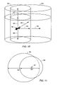
- FIG. 6 depicts an example of a normal exclusive area for an aircraft.
- Exclusive area volume 336 may be a volume in space.
- exclusive area volume 336 may be an area in space.
- Exclusive area volume 336 may be defined by boundary conditions such as vertical height 338 and horizontal area 340 . In some embodiments, other boundary conditions may define exclusive area volume 336 .
- An alarm may be activated when vessel 302 enters exclusive area volume 336 .
- boundary conditions for an alert may be defined by a user of a vessel tracking system.
- boundary conditions may be defined by a user using a graphical interface.
- boundary conditions may be defined by using a “point and click” interface on a display (e.g., a map display).
- boundary conditions may be predefined in a vessel tracking system.
- boundary conditions may be predefined on a map entered into a vessel tracking system.
- a user of the vessel tracking system may modify the boundary conditions (e.g., using a graphical “point and click” interface or a graphical “point and drag” interface).
- a user may be inhibited from modifying the boundary conditions for an alert.
- a visual alarm may include an alert window on a display.
- FIG. 7 depicts an example of display 300 of a vessel track and an alert window.
- Display 300 may show a track of vessel 302 . If vessel 302 violates the boundary conditions for an alert (e.g., a boundary alert), alert window 312 may automatically appear on display 300 .
- Alert window 312 may be an inset window on display 300 .
- a user may be prompted to open alert window 312 . More than one alert window 312 may appear on display 300 . For example, multiple alert windows 312 may appear for a single vessel violating boundary conditions for more than one alert and/or alert windows 312 may appear for several vessels.
- Alert window 312 may have a size, zoom level, and/or screen position predetermined by a user or an operator of a vessel tracking system. The size, zoom level, and/or screen position of alert window 312 may also be modified after the alert window appears on display 300 .
- alert window 312 may be include a color border (e.g., a red border) and/or may be associated with an audio alarm.
- a vessel tracking functional component may include a component that identifies and alerts a user of a vessel that exceeds normal travel characteristics (e.g., an aircraft that exceeds a normal flight envelope or has abnormal flight characteristics).
- a vessel tracking functional component may automatically identify and alert a user of a vessel that exceeds normal travel characteristics.
- flight characteristics may include, but are not limited to, horizontal velocity (distance per time (e.g., knots)), vertical velocity (distance per time (e.g., feet per minute)), rate of heading change (heading per time (e.g., degrees per second), altitude, heading, speed change (either horizontal, vertical, or normalized) (velocity change per time (e.g., knots per second)), IFF signal loss (the maximum amount of time an aircraft may not report IFF before generating an alert condition), route deviation distance (the maximum distance an aircraft may deviate from a planned route of flight between two points before generating an alert condition), and route deviation angle (the maximum angle an aircraft may deviate from a planned route of flight between two points before generating an alert condition).
- Route deviation angle may typically allow for route angle deviations caused by aircraft spacing, weather, and/or direct routing changes.
- FIG. 8A depicts a flowchart for an embodiment for tracking a vessel.
- vessel tracking system 400 may monitor one or more flight characteristics 402 of an aircraft.
- the flight characteristics of the aircraft may be used to assess (e.g., determine) dynamic state 404 of the aircraft (i.e., the in-flight conditions of the aircraft).
- a functional component of the vessel tracking system e.g., HDNATM
- normal flight characteristics 408 i.e., flight characteristics of a normal dynamic state 410
- the alert condition of the aircraft may be raised. For example, if the horizontal velocity (i.e., speed) of an aircraft exceeds a predetermined horizontal velocity for the aircraft, the alert condition for the aircraft may be raised. If the aircraft's horizontal velocity returns to a value below the predetermined horizontal velocity, the alert condition for the aircraft may return to its prior level.
- Predetermined values for normal flight characteristics may be defined by a user of a vessel tracking system. Predetermined values for normal flight characteristics may be based on, for example, vessel type, vessel location, vessel route, etc.
- the alert condition or the change in alert condition for the aircraft may be reported 414 to a user of a vessel tracking system.
- the alert condition for the aircraft may be visually reported to the user.
- the alert condition may be identified on a visual display available to the user.
- FIG. 3 depicts an example of alert condition level 310 identified for vessel 302 .
- Alert condition level 310 may not be shown when vessel 302 is not in a raised alert condition.
- the alert condition for a vessel may have more than one alert condition level (e.g., 3, 4, 5, or more alert condition levels).
- an aircraft may have a set of predetermined horizontal velocities, predetermined vertical velocities, and/or predetermined heading change rates. If the horizontal velocity, vertical velocity, and/or heading change rate of the aircraft deviates from (e.g., exceeds) the predetermined values, the alert condition for the aircraft may be raised.
- an aircraft may have more than one predetermined value for any of the flight characteristics (e.g., horizontal velocity). Each predetermined flight characteristic value may correspond to a selected increase in the alert condition for the aircraft.
- an aircraft may have a first predetermined horizontal velocity for a first alert condition level, a second predetermined horizontal velocity (e.g., a horizontal velocity higher than the first predetermined horizontal velocity) for a second alert condition level, a third predetermined horizontal velocity for a third alert condition level, etc.
- a second predetermined horizontal velocity e.g., a horizontal velocity higher than the first predetermined horizontal velocity
- a third predetermined horizontal velocity for a third alert condition level
- boundary conditions for an alert may be increased to enclose more volume or area when the alert condition of a vessel increases.
- a vessel tracking system functional component e.g., HDNATM
- HDNATM may automatically increase the boundary conditions for an alert.
- Increasing the boundary conditions for an alert when the alert condition of a vessel increases provides an earlier alarm to allow a user greater lead-time in dealing with the alarm. Allowing a user a greater lead-time to deal with the alarm may increase the time and the ability of the user to determine a response (e.g., a solution) to the alarm and avert a dangerous or life-threatening situation.
- predetermined values for normal flight characteristics may be modified (e.g., raised or lowered) based on a flight phase of a vessel.
- Flight phases may include, but are not limited to, takeoff, enroute, terminal or approach, and landing.
- alert condition levels may vary based on a flight phase of a vessel. For example, a high vertical velocity and rapid rate of heading change may produce a higher alert condition level for an aircraft enroute than for an aircraft during its approach.
- the flight phase of an aircraft may be input by a user of a vessel tracking system or may be automatically assessed by the vessel tracking system (e.g., based on a location of the vessel or based on which sensing system is tracking the vessel).
- FIG. 5 depicts an example of normal area boundary 330 and increased area boundaries 332 , 334 .
- Area boundaries 332 , 334 may have increased areas or volumes compared to normal area boundary 330 .
- the area or volume of an area boundary may be increased because a flight characteristic of vessel 302 exceeds a predetermined value of a normal flight characteristic.
- FIG. 8 depicts an example of a proximity alert volume for an aircraft with an increased vertical area relative to the normal proximity alert volume depicted in FIG. 4 .
- vessel 302 may have vertical velocity 350 that exceeds a predetermined value and thus raises the alert condition of the vessel.
- a vessel tracking system functional component may automatically increase vertical distance 322 by vertical distance 352 in the direction of the vertical velocity (e.g., upwards). Increasing the vertical distance increases the alert volume from normal proximity alert volume 320 to extended proximity alert volume 354 .
- FIG. 9 depicts an example of a proximity alert volume for an aircraft with an increased horizontal area relative to the normal proximity alert volume depicted in FIG. 4 .
- vessel 302 may have horizontal velocity 356 that exceeds a predetermined value and thus raises the alert condition of the vessel.
- a vessel tracking system functional component may automatically increase normal proximity alert volume 320 to extended proximity alert volume 354 .
- Extended proximity alert volume 354 may be increased in the look ahead direction for vessel 302 due to the increased horizontal velocity while the look behind area may be decreased, as shown in FIG. 9 .
- the look behind area may remain substantially the same for normal proximity alert volume 320 and extended proximity alert volume 354 .
- FIG. 10 depicts an example of a proximity alert volume for an aircraft with increased vertical area and increased horizontal area relative to the normal proximity alert volume depicted in FIG. 4 .
- extended proximity alert volume 354 may be increased in both the vertical and horizontal directions.
- FIG. 11 depicts a top view of the proximity alert volume of FIG. 10 showing both normal and increased horizontal areas and horizontal look ahead point.
- Look ahead point 358 may be determined by selecting a look ahead time frame and multiplying the look ahead time frame by the horizontal velocity of the vessel.
- FIG. 12 depicts sets of values for maximum vertical proximity alert volume extent 360 in feet and maximum vertical look ahead travel 362 in feet along with vertical velocity 364 in feet per minute determined in the example.
- FIG. 12 shows the relationships between vertical proximity alert volume, maximum vertical look ahead travel, and vertical velocity for several events according to the example.
- FIG. 13 depicts values for maximum horizontal proximity alert volume extent 366 and maximum horizontal look ahead travel 368 versus horizontal velocity (knots) determined in the example.
- FIG. 13 shows the changes in horizontal proximity alert volume for various parameters according to the example.
- FIG. 14 depicts straight-line distance to a boundary of the proximity alert volume versus angle relative to aircraft direction determined in the example for an aircraft horizontal velocity of 650 knots.
- a vessel tracking system functional component may be adapted for security applications (e.g., Homeland Air Security applications).
- a vessel tracking system may be coupled (e.g., linked through the Internet) to a flight data system (e.g., the Federal Aviation Administration's (FAA's) flight data system.
- Alerts may be provided for prohibited areas (e.g., boundary alerts) and/or prohibited routes (e.g., exclusive area alerts).
- Aircraft that deviate or exceed predetermined flight characteristics may be identified as “special interest” aircraft.
- a vessel tracking system may include a buffered display system.
- a buffered display system may allow a user to view a replay of what has appeared on a display in one window (e.g., an inset window) while real-time data is displayed in another window (e.g., a main window).
- a buffered display system may allow for up to about 5 minutes of replay. Using a buffered display system may allow for more immediate access to replay footage to improve analysis of the travel characteristics of a vessel.
Abstract
Description
Claims (96)
Priority Applications (1)
| Application Number | Priority Date | Filing Date | Title |
|---|---|---|---|
| US10/823,988 US7259693B2 (en) | 2004-04-14 | 2004-04-14 | Air vessel tracking system and method |
Applications Claiming Priority (1)
| Application Number | Priority Date | Filing Date | Title |
|---|---|---|---|
| US10/823,988 US7259693B2 (en) | 2004-04-14 | 2004-04-14 | Air vessel tracking system and method |
Publications (2)
| Publication Number | Publication Date |
|---|---|
| US20070146167A1 US20070146167A1 (en) | 2007-06-28 |
| US7259693B2 true US7259693B2 (en) | 2007-08-21 |
Family
ID=38192957
Family Applications (1)
| Application Number | Title | Priority Date | Filing Date |
|---|---|---|---|
| US10/823,988 Active 2025-05-31 US7259693B2 (en) | 2004-04-14 | 2004-04-14 | Air vessel tracking system and method |
Country Status (1)
| Country | Link |
|---|---|
| US (1) | US7259693B2 (en) |
Cited By (11)
| Publication number | Priority date | Publication date | Assignee | Title |
|---|---|---|---|---|
| US20080010005A1 (en) * | 2006-07-10 | 2008-01-10 | Small Gregory J | Methods and systems for aircraft departure enhanced situational awareness and recovery |
| US20080010107A1 (en) * | 2006-07-10 | 2008-01-10 | Small Gregory J | Methods and systems for providing a global view of airline operations |
| US20080046167A1 (en) * | 2006-07-10 | 2008-02-21 | Small Gregory J | Methods and systems for providing a resource management view for airline operations |
| US20090113028A1 (en) * | 2007-10-25 | 2009-04-30 | Morris Timothy R | Network-centric processing |
| US20100030804A1 (en) * | 2008-07-31 | 2010-02-04 | International Business Machines Corporation | Synchronization of Locations in Real and Virtual Worlds |
| US20100073363A1 (en) * | 2008-09-05 | 2010-03-25 | Gilray Densham | System and method for real-time environment tracking and coordination |
| US20120116611A1 (en) * | 2010-11-04 | 2012-05-10 | The Boeing Company | Managing Control Surfaces for an Aircraft |
| US8890744B1 (en) | 1999-04-07 | 2014-11-18 | James L. Geer | Method and apparatus for the detection of objects using electromagnetic wave attenuation patterns |
| EP3547284A1 (en) * | 2018-03-26 | 2019-10-02 | Honeywell International Inc. | Method and system for generating an alert for an aircraft potentially exceeding speed limits in restricted airspace |
| RU2714614C1 (en) * | 2019-05-22 | 2020-02-18 | Закрытое акционерное общество "ИНТЕГРА-С" | System for detection and tracking of vessels in water area of boundary zone |
| US20220246041A1 (en) * | 2017-09-13 | 2022-08-04 | Flirtey Holdings, Inc. | Aerial vehicle detection system |
Families Citing this family (9)
| Publication number | Priority date | Publication date | Assignee | Title |
|---|---|---|---|---|
| US20070120708A1 (en) * | 2005-09-09 | 2007-05-31 | Honeywell International Inc. | Methods and systems for monitoring aircraft approach between approach gates |
| US7992094B2 (en) * | 2007-08-14 | 2011-08-02 | International Business Machines Corporation | Intelligence driven icons and cursors |
| US7818412B2 (en) * | 2008-06-27 | 2010-10-19 | Microsoft Corporation | Selection of sensors for monitoring phenomena considering the value of information and data sharing preferences |
| FR3004574B1 (en) * | 2013-04-16 | 2016-09-02 | Prodose | RAILWAY MONITORING DEVICE AND WORKING METHOD |
| CN105247593B (en) | 2014-04-17 | 2017-04-19 | 深圳市大疆创新科技有限公司 | Flight control for flight-restricted regions |
| CN107407938B (en) | 2015-03-31 | 2021-04-02 | 深圳市大疆创新科技有限公司 | Open platform for flight-limiting area |
| WO2019146581A1 (en) * | 2018-01-23 | 2019-08-01 | 株式会社Nttドコモ | Information processing device and information processing method |
| CN111766896B (en) * | 2020-07-10 | 2023-12-29 | 珠海紫燕无人飞行器有限公司 | Unmanned aerial vehicle control method and system based on movable base |
| EP3979034A1 (en) * | 2020-10-05 | 2022-04-06 | Advanced Laboratory on Embedded Systems S.r.l. | Safety monitor |
Citations (14)
| Publication number | Priority date | Publication date | Assignee | Title |
|---|---|---|---|---|
| US5382954A (en) * | 1993-05-27 | 1995-01-17 | Honeywell Inc. | Resolution advisory display instrument for TCAS guidance |
| US6208284B1 (en) * | 1998-06-16 | 2001-03-27 | Rockwell Science Center, Inc. | Radar augmented TCAS |
| US6249421B1 (en) | 1999-09-13 | 2001-06-19 | The United States Of America As Represented By The Secretary Of The Army | Electrostatic actuation control system |
| US6587046B2 (en) | 1996-03-27 | 2003-07-01 | Raymond Anthony Joao | Monitoring apparatus and method |
| US6658349B2 (en) | 2001-05-14 | 2003-12-02 | James Douglas Cline | Method and system for marine vessel tracking system |
| US6668218B1 (en) | 2002-03-27 | 2003-12-23 | Lockheed Martin Corporation | Method and system for target localization |
| US6675095B1 (en) * | 2001-12-15 | 2004-01-06 | Trimble Navigation, Ltd | On-board apparatus for avoiding restricted air space in non-overriding mode |
| US6677889B2 (en) | 2002-01-22 | 2004-01-13 | Raytheon Company | Auto-docking system |
| US6687637B2 (en) | 2001-06-18 | 2004-02-03 | Globvision Inc. | Data sensor validation system and method |
| US6707394B2 (en) * | 1999-02-01 | 2004-03-16 | Honeywell, Inc. | Apparatus, method, and computer program product for generating terrain clearance floor envelopes about a selected runway |
| US6778906B1 (en) * | 2001-08-14 | 2004-08-17 | The United States Of America As Represented By The Secretary Of The Navy | Apparatus and method for ensuring retention of situational awareness by employing an active network guidance and emergency logic (angel) system |
| US6940426B1 (en) * | 2003-09-05 | 2005-09-06 | Ridgeback Systems Llc | Aircraft flight risk measuring system and method of operation |
| US7131136B2 (en) * | 2002-07-10 | 2006-10-31 | E-Watch, Inc. | Comprehensive multi-media surveillance and response system for aircraft, operations centers, airports and other commercial transports, centers and terminals |
| US7161501B1 (en) * | 2004-09-22 | 2007-01-09 | The United States Of America As Represented By The Administrator Of The National Aeronautics And Space Administration | Historical analysis of aircraft flight parameters |
-
2004
- 2004-04-14 US US10/823,988 patent/US7259693B2/en active Active
Patent Citations (14)
| Publication number | Priority date | Publication date | Assignee | Title |
|---|---|---|---|---|
| US5382954A (en) * | 1993-05-27 | 1995-01-17 | Honeywell Inc. | Resolution advisory display instrument for TCAS guidance |
| US6587046B2 (en) | 1996-03-27 | 2003-07-01 | Raymond Anthony Joao | Monitoring apparatus and method |
| US6208284B1 (en) * | 1998-06-16 | 2001-03-27 | Rockwell Science Center, Inc. | Radar augmented TCAS |
| US6707394B2 (en) * | 1999-02-01 | 2004-03-16 | Honeywell, Inc. | Apparatus, method, and computer program product for generating terrain clearance floor envelopes about a selected runway |
| US6249421B1 (en) | 1999-09-13 | 2001-06-19 | The United States Of America As Represented By The Secretary Of The Army | Electrostatic actuation control system |
| US6658349B2 (en) | 2001-05-14 | 2003-12-02 | James Douglas Cline | Method and system for marine vessel tracking system |
| US6687637B2 (en) | 2001-06-18 | 2004-02-03 | Globvision Inc. | Data sensor validation system and method |
| US6778906B1 (en) * | 2001-08-14 | 2004-08-17 | The United States Of America As Represented By The Secretary Of The Navy | Apparatus and method for ensuring retention of situational awareness by employing an active network guidance and emergency logic (angel) system |
| US6675095B1 (en) * | 2001-12-15 | 2004-01-06 | Trimble Navigation, Ltd | On-board apparatus for avoiding restricted air space in non-overriding mode |
| US6677889B2 (en) | 2002-01-22 | 2004-01-13 | Raytheon Company | Auto-docking system |
| US6668218B1 (en) | 2002-03-27 | 2003-12-23 | Lockheed Martin Corporation | Method and system for target localization |
| US7131136B2 (en) * | 2002-07-10 | 2006-10-31 | E-Watch, Inc. | Comprehensive multi-media surveillance and response system for aircraft, operations centers, airports and other commercial transports, centers and terminals |
| US6940426B1 (en) * | 2003-09-05 | 2005-09-06 | Ridgeback Systems Llc | Aircraft flight risk measuring system and method of operation |
| US7161501B1 (en) * | 2004-09-22 | 2007-01-09 | The United States Of America As Represented By The Administrator Of The National Aeronautics And Space Administration | Historical analysis of aircraft flight parameters |
Cited By (19)
| Publication number | Priority date | Publication date | Assignee | Title |
|---|---|---|---|---|
| US8890744B1 (en) | 1999-04-07 | 2014-11-18 | James L. Geer | Method and apparatus for the detection of objects using electromagnetic wave attenuation patterns |
| US7747382B2 (en) * | 2006-07-10 | 2010-06-29 | The Boeing Company | Methods and systems for real-time enhanced situational awareness |
| US20080010107A1 (en) * | 2006-07-10 | 2008-01-10 | Small Gregory J | Methods and systems for providing a global view of airline operations |
| US20080010004A1 (en) * | 2006-07-10 | 2008-01-10 | Small Gregory J | Methods and systems for real-time enhanced situational awareness |
| US20080046167A1 (en) * | 2006-07-10 | 2008-02-21 | Small Gregory J | Methods and systems for providing a resource management view for airline operations |
| US20080010005A1 (en) * | 2006-07-10 | 2008-01-10 | Small Gregory J | Methods and systems for aircraft departure enhanced situational awareness and recovery |
| US7813871B2 (en) | 2006-07-10 | 2010-10-12 | The Boeing Company | Methods and systems for aircraft departure enhanced situational awareness and recovery |
| US20090113028A1 (en) * | 2007-10-25 | 2009-04-30 | Morris Timothy R | Network-centric processing |
| US8140289B2 (en) * | 2007-10-25 | 2012-03-20 | Raytheon Company | Network-centric processing |
| US20100030804A1 (en) * | 2008-07-31 | 2010-02-04 | International Business Machines Corporation | Synchronization of Locations in Real and Virtual Worlds |
| US20100073363A1 (en) * | 2008-09-05 | 2010-03-25 | Gilray Densham | System and method for real-time environment tracking and coordination |
| US8639666B2 (en) | 2008-09-05 | 2014-01-28 | Cast Group Of Companies Inc. | System and method for real-time environment tracking and coordination |
| US8938431B2 (en) | 2008-09-05 | 2015-01-20 | Cast Group Of Companies Inc. | System and method for real-time environment tracking and coordination |
| US20120116611A1 (en) * | 2010-11-04 | 2012-05-10 | The Boeing Company | Managing Control Surfaces for an Aircraft |
| US8290639B2 (en) * | 2010-11-04 | 2012-10-16 | The Boeing Company | Managing control surfaces for an aircraft |
| US20220246041A1 (en) * | 2017-09-13 | 2022-08-04 | Flirtey Holdings, Inc. | Aerial vehicle detection system |
| EP3547284A1 (en) * | 2018-03-26 | 2019-10-02 | Honeywell International Inc. | Method and system for generating an alert for an aircraft potentially exceeding speed limits in restricted airspace |
| US10569898B2 (en) | 2018-03-26 | 2020-02-25 | Honeywell International Inc. | Method and system for generating an alert for an aircraft potentially exceeding speed limits in restricted airspace |
| RU2714614C1 (en) * | 2019-05-22 | 2020-02-18 | Закрытое акционерное общество "ИНТЕГРА-С" | System for detection and tracking of vessels in water area of boundary zone |
Also Published As
| Publication number | Publication date |
|---|---|
| US20070146167A1 (en) | 2007-06-28 |
Similar Documents
| Publication | Publication Date | Title |
|---|---|---|
| US7259693B2 (en) | Air vessel tracking system and method | |
| Lim et al. | Avionics human-machine interfaces and interactions for manned and unmanned aircraft | |
| US10467913B1 (en) | Flight assistant | |
| US9310222B1 (en) | Flight assistant with automatic configuration and landing site selection method and apparatus | |
| US8378852B2 (en) | Aircraft-centered ground maneuvering monitoring and alerting system | |
| EP1185849B1 (en) | Method and electronic circuit for predicting intensity and location of a wake vortex | |
| US7411519B1 (en) | System and method for predicting and displaying wake vortex turbulence | |
| US20090012661A1 (en) | Device and method for changing the zones prohibited to an aircraft | |
| US7522088B2 (en) | System and method for monitoring airspace | |
| CN106546984A (en) | The performance of airborne weather radar is improved using outside weather data | |
| CN105270642B (en) | System and method for displaying degraded intruder traffic data on an aircraft display | |
| WO2022172103A1 (en) | Radar system device and method for corroborating human reports on high-risk, search & response incidents | |
| Wu et al. | Well clear trade study for unmanned aircraft system detect and avoid with non-cooperative aircraft | |
| Suplisson | Optimal recovery trajectories for automatic ground collision avoidance systems (auto gcas) | |
| Shakernia et al. | Sense and avoid (SAA) flight test and lessons learned | |
| Zeitlin | Sense & avoid capability development challenges | |
| US20210343169A1 (en) | System and method for identification and assessment of abnormal behavior of nearby aircraft | |
| Wilson | The use of low-cost mobile radar systems for small UAS sense and avoid | |
| Boskovic et al. | Sensor and tracker requirements development for sense and avoid systems for unmanned aerial vehicles | |
| US11657721B1 (en) | Aircraft with flight assistant | |
| Rand et al. | Algorithms for airborne conflict detection, prevention, and resolution | |
| Calhoun et al. | UAS sense and avoid system interface design and evaluation | |
| Fang | Risk-based supervisory guidance for detect and avoid involving small unmanned aircraft systems | |
| Ramasamy | Next generation flight management systems for manned and unmanned aircraft operations-automated separation assurance and collision avoidance functionalities | |
| Stamm et al. | Unmanned aircraft sense and avoid: Leveraging ATC infrastructure |
Legal Events
| Date | Code | Title | Description |
|---|---|---|---|
| STCF | Information on status: patent grant |
Free format text: PATENTED CASE |
|
| FPAY | Fee payment |
Year of fee payment: 4 |
|
| AS | Assignment |
Owner name: COMPUTER SCIENCES CORPORATION, VIRGINIA Free format text: ASSIGNMENT OF ASSIGNORS INTEREST;ASSIGNORS:MILLER, RUSSELL E.;DICKERSON, BRIAN D.;MCKEE, TERYLE B.;REEL/FRAME:030177/0059 Effective date: 20130409 |
|
| AS | Assignment |
Owner name: DYNCORP, VIRGINIA Free format text: ASSIGNMENT OF ASSIGNORS INTEREST;ASSIGNOR:COMPUTER SCIENCES CORPORATION;REEL/FRAME:030807/0123 Effective date: 20130716 |
|
| FPAY | Fee payment |
Year of fee payment: 8 |
|
| AS | Assignment |
Owner name: BANK OF AMERICA, N.A., AS ADMINISTRATIVE AGENT, TE Free format text: SECURITY AGREEMENT;ASSIGNORS:A-T SOLUTIONS, INC.;DYNCORP;REEL/FRAME:038106/0389 Effective date: 20160314 |
|
| AS | Assignment |
Owner name: A-T SOLUTIONS, INC., VIRGINIA Free format text: RELEASE BY SECURED PARTY;ASSIGNOR:BANK OF AMERICA, N.A., AS ADMINISTRATIVE AGENT;REEL/FRAME:040083/0906 Effective date: 20161020 Owner name: DYNCORP, VIRGINIA Free format text: RELEASE BY SECURED PARTY;ASSIGNOR:BANK OF AMERICA, N.A., AS ADMINISTRATIVE AGENT;REEL/FRAME:040083/0906 Effective date: 20161020 |
|
| AS | Assignment |
Owner name: BANK OF AMERICA, N.A., AS COLLATERAL AGENT, TEXAS Free format text: FIRST LIEN SECURITY AGREEMENT;ASSIGNORS:A-T SOLUTIONS, INC.;DYNCORP;REEL/FRAME:040260/0039 Effective date: 20161020 |
|
| AS | Assignment |
Owner name: BANK OF AMERICA, N.A., AS COLLATERAL AGENT, TEXAS Free format text: SECOND LIEN SECURITY AGREEMENT;ASSIGNORS:A-T SOLUTIONS, INC.;DYNCORP;REEL/FRAME:040473/0350 Effective date: 20161020 |
|
| AS | Assignment |
Owner name: BANK OF AMERICA, N.A., AS COLLATERAL AGENT, TEXAS Free format text: ABL LIEN SECURITY AGREEMENT;ASSIGNORS:A-T SOLUTIONS, INC.;DYNCORP;REEL/FRAME:040491/0354 Effective date: 20161020 |
|
| FEPP | Fee payment procedure |
Free format text: MAINTENANCE FEE REMINDER MAILED (ORIGINAL EVENT CODE: REM.); ENTITY STATUS OF PATENT OWNER: LARGE ENTITY |
|
| FEPP | Fee payment procedure |
Free format text: 11.5 YR SURCHARGE- LATE PMT W/IN 6 MO, LARGE ENTITY (ORIGINAL EVENT CODE: M1556); ENTITY STATUS OF PATENT OWNER: LARGE ENTITY |
|
| MAFP | Maintenance fee payment |
Free format text: PAYMENT OF MAINTENANCE FEE, 12TH YEAR, LARGE ENTITY (ORIGINAL EVENT CODE: M1553); ENTITY STATUS OF PATENT OWNER: LARGE ENTITY Year of fee payment: 12 |
|
| AS | Assignment |
Owner name: DYNCORP, LLC (F/K/A DYNCORP), VIRGINIA Free format text: RELEASE BY SECURED PARTY;ASSIGNOR:BANK OF AMERICA, N.A.;REEL/FRAME:054104/0329 Effective date: 20201019 Owner name: PAE NATIONAL SECURITY SOLUTIONS LLC (F/K/A A-T SOLUTIONS, INC.), VIRGINIA Free format text: RELEASE BY SECURED PARTY;ASSIGNOR:BANK OF AMERICA, N.A.;REEL/FRAME:054104/0329 Effective date: 20201019 |
|
| AS | Assignment |
Owner name: DYNCORP LLC, VIRGINIA Free format text: RELEASE BY SECURED PARTY;ASSIGNOR:BANK OF AMERICA, N.A., AS COLLATERAL AGENT;REEL/FRAME:059024/0086 Effective date: 20220215 Owner name: DYNCORP LLC, VIRGINIA Free format text: RELEASE BY SECURED PARTY;ASSIGNOR:BANK OF AMERICA, N.A., AS COLLATERAL AGENT;REEL/FRAME:059024/0103 Effective date: 20220215 |
|
| AS | Assignment |
Owner name: ROYAL BANK OF CANADA, AS ADMINISTRATIVE AGENT, CANADA Free format text: SECURITY INTEREST;ASSIGNORS:CENTRA TECHNOLOGY INC.;DELTA BRIDGE, INC.;DYNCORP LLC;AND OTHERS;REEL/FRAME:059221/0734 Effective date: 20220215 Owner name: JPMORGAN CHASE BANK, N.A., AS ADMINISTRATIVE AGENT, ILLINOIS Free format text: SECURITY INTEREST;ASSIGNORS:CENTRA TECHNOLOGY INC.;DELTA BRIDGE, INC.;DYNCORP LLC;AND OTHERS;REEL/FRAME:059221/0723 Effective date: 20220215 |