US7278752B2 - Device for providing internal illumination of live flowers and other products - Google Patents
Device for providing internal illumination of live flowers and other products Download PDFInfo
- Publication number
- US7278752B2 US7278752B2 US11/076,671 US7667105A US7278752B2 US 7278752 B2 US7278752 B2 US 7278752B2 US 7667105 A US7667105 A US 7667105A US 7278752 B2 US7278752 B2 US 7278752B2
- Authority
- US
- United States
- Prior art keywords
- light source
- tube
- case
- plant
- penetrating tip
- Prior art date
- Legal status (The legal status is an assumption and is not a legal conclusion. Google has not performed a legal analysis and makes no representation as to the accuracy of the status listed.)
- Expired - Fee Related, expires
Links
Images


Classifications
-
- F—MECHANICAL ENGINEERING; LIGHTING; HEATING; WEAPONS; BLASTING
- F21—LIGHTING
- F21V—FUNCTIONAL FEATURES OR DETAILS OF LIGHTING DEVICES OR SYSTEMS THEREOF; STRUCTURAL COMBINATIONS OF LIGHTING DEVICES WITH OTHER ARTICLES, NOT OTHERWISE PROVIDED FOR
- F21V33/00—Structural combinations of lighting devices with other articles, not otherwise provided for
- F21V33/0004—Personal or domestic articles
- F21V33/0024—Household or table equipment
- F21V33/0028—Decorative household equipment, e.g. plant holders or food dummies
-
- A—HUMAN NECESSITIES
- A01—AGRICULTURE; FORESTRY; ANIMAL HUSBANDRY; HUNTING; TRAPPING; FISHING
- A01G—HORTICULTURE; CULTIVATION OF VEGETABLES, FLOWERS, RICE, FRUIT, VINES, HOPS OR SEAWEED; FORESTRY; WATERING
- A01G5/00—Floral handling
-
- A—HUMAN NECESSITIES
- A01—AGRICULTURE; FORESTRY; ANIMAL HUSBANDRY; HUNTING; TRAPPING; FISHING
- A01G—HORTICULTURE; CULTIVATION OF VEGETABLES, FLOWERS, RICE, FRUIT, VINES, HOPS OR SEAWEED; FORESTRY; WATERING
- A01G7/00—Botany in general
- A01G7/04—Electric or magnetic or acoustic treatment of plants for promoting growth
- A01G7/045—Electric or magnetic or acoustic treatment of plants for promoting growth with electric lighting
-
- A—HUMAN NECESSITIES
- A01—AGRICULTURE; FORESTRY; ANIMAL HUSBANDRY; HUNTING; TRAPPING; FISHING
- A01G—HORTICULTURE; CULTIVATION OF VEGETABLES, FLOWERS, RICE, FRUIT, VINES, HOPS OR SEAWEED; FORESTRY; WATERING
- A01G9/00—Cultivation in receptacles, forcing-frames or greenhouses; Edging for beds, lawn or the like
- A01G9/24—Devices or systems for heating, ventilating, regulating temperature, illuminating, or watering, in greenhouses, forcing-frames, or the like
- A01G9/249—Lighting means
-
- F—MECHANICAL ENGINEERING; LIGHTING; HEATING; WEAPONS; BLASTING
- F21—LIGHTING
- F21S—NON-PORTABLE LIGHTING DEVICES; SYSTEMS THEREOF; VEHICLE LIGHTING DEVICES SPECIALLY ADAPTED FOR VEHICLE EXTERIORS
- F21S9/00—Lighting devices with a built-in power supply; Systems employing lighting devices with a built-in power supply
- F21S9/02—Lighting devices with a built-in power supply; Systems employing lighting devices with a built-in power supply the power supply being a battery or accumulator
-
- G—PHYSICS
- G02—OPTICS
- G02B—OPTICAL ELEMENTS, SYSTEMS OR APPARATUS
- G02B6/00—Light guides; Structural details of arrangements comprising light guides and other optical elements, e.g. couplings
- G02B6/0001—Light guides; Structural details of arrangements comprising light guides and other optical elements, e.g. couplings specially adapted for lighting devices or systems
- G02B6/0005—Light guides; Structural details of arrangements comprising light guides and other optical elements, e.g. couplings specially adapted for lighting devices or systems the light guides being of the fibre type
- G02B6/0008—Light guides; Structural details of arrangements comprising light guides and other optical elements, e.g. couplings specially adapted for lighting devices or systems the light guides being of the fibre type the light being emitted at the end of the fibre
-
- F—MECHANICAL ENGINEERING; LIGHTING; HEATING; WEAPONS; BLASTING
- F21—LIGHTING
- F21Y—INDEXING SCHEME ASSOCIATED WITH SUBCLASSES F21K, F21L, F21S and F21V, RELATING TO THE FORM OR THE KIND OF THE LIGHT SOURCES OR OF THE COLOUR OF THE LIGHT EMITTED
- F21Y2115/00—Light-generating elements of semiconductor light sources
- F21Y2115/10—Light-emitting diodes [LED]
-
- Y—GENERAL TAGGING OF NEW TECHNOLOGICAL DEVELOPMENTS; GENERAL TAGGING OF CROSS-SECTIONAL TECHNOLOGIES SPANNING OVER SEVERAL SECTIONS OF THE IPC; TECHNICAL SUBJECTS COVERED BY FORMER USPC CROSS-REFERENCE ART COLLECTIONS [XRACs] AND DIGESTS
- Y02—TECHNOLOGIES OR APPLICATIONS FOR MITIGATION OR ADAPTATION AGAINST CLIMATE CHANGE
- Y02P—CLIMATE CHANGE MITIGATION TECHNOLOGIES IN THE PRODUCTION OR PROCESSING OF GOODS
- Y02P60/00—Technologies relating to agriculture, livestock or agroalimentary industries
- Y02P60/14—Measures for saving energy, e.g. in green houses
-
- Y—GENERAL TAGGING OF NEW TECHNOLOGICAL DEVELOPMENTS; GENERAL TAGGING OF CROSS-SECTIONAL TECHNOLOGIES SPANNING OVER SEVERAL SECTIONS OF THE IPC; TECHNICAL SUBJECTS COVERED BY FORMER USPC CROSS-REFERENCE ART COLLECTIONS [XRACs] AND DIGESTS
- Y10—TECHNICAL SUBJECTS COVERED BY FORMER USPC
- Y10S—TECHNICAL SUBJECTS COVERED BY FORMER USPC CROSS-REFERENCE ART COLLECTIONS [XRACs] AND DIGESTS
- Y10S362/00—Illumination
- Y10S362/805—Horticultural
Definitions
- This invention is directed to the field of illumination and in particular to the illumination of floral displays.
- flowers and floral arrangements have been used throughout history as gifts and to convey sentiments.
- a single, long-stemmed rose can be an elegant expression of passion, while an elaborate floral bouquet might be used to celebrate a wedding or the birth of a child.
- the intricate designs and colorful patterns of flowers make them true objects of beauty.
- Each flower is unique, having its own particular shape and coloring.
- Fresh flowers may also produce a pleasant fragrance that adds to the experience when a flower or bouquet is presented. Since the blossoms of flowering plants are typically short-lived, their transitory nature and short life makes them particularly special. While the visual beauty of these flowers is stunning, it can only be enjoyed when illuminated. This is unfortunate, since many of the locations where flowers are used are in areas of reduced lighting such as restaurants or dance venues.
- Deng U.S. application US2004/00885758, discloses a means for lighting artificial flowers employing a small light bulb or light emitting diode.
- a flower is assembled around the lighting means. When power is applied to the lamp, the artificial flower illuminates from within.
- Harris, U.S. Pat. No. 5,063,485, discloses an illuminated artificial flower arrangement that includes a container with an electrical terminal block being mounted on the stem support.
- U.S. Pat. No. 4,616,304 teaches a device for displaying three-dimensional objects to be centripetally viewed such as flower arrangements.
- the light source is contained in a lower cavity while the flowers are contained in an upper cavity.
- Kurita et al. U.S. Pat. No. 4,399,439, discloses an illuminated artificial flower ornament in which a miniature bulb is located in the peduncle part of an artificial flower.
- Fernandez U.S. Pat. No. 4,125,462 discloses a method for making a translucent optical diffuser for a flower lamp. A method of chemically treating animal bladders to convert them into diffusers is also disclosed.
- U.S. Pat. No. 6,076,940 discloses a planter light accessory for illuminating a plant within a container.
- a cylindrical housing contains a light source that is mounted on the edge of the cylindrical housing for illuminating the plant.
- Huang U.S. Pat. No. 5,947,582, discloses a flower shaped lamp including a mount for an artificial flower.
- a tubular stem of the artificial flower contains an electric wire that is connected to a bulb that is mounted on the artificial flower.
- U.S. Pat. No. 4,626,968 discloses a device and a system for indirect, substantially glare-free, directional lighting of objects such as plants and outdoor sculptures.
- U.S. Pat. No. 4,325,110 discloses a vase-type illumination device comprising a transparent container, transparent base board, and a supporting stand and illuminating mechanism.
- the transparent base board can be either movably or immovably mounted on the underside of said container, while the flowers or various kinds of ornaments are inserted in place in the holding hole on the base board.
- U.S. Pat. No. 3,431,410 discloses an ornamental display having a multiplicity of fiber optic elements held together along a length adjacent one end and transversely unrestrained at the other end.
- a light source and a rotatable color wheel are positioned between the light source and the fiber bundle.
- Feldman U.S. Pat. No. 5,951,140, discloses a display unit, typically intended for placement on a table that includes a plurality of flexible elongated electroluminescent sources connected to the individual display elements.
- Sussel U.S. Pat. No. 4,170,036, discloses an article of jewelry which consists of first and second lengths of electrically conductive wire with a light emitting diode connected across a first set of the free ends of the wire lengths.
- An oscillator circuit and a low voltage power source are connected across the other free ends of the lengths of wire to provide a flashing circuit for the light emitting diode.
- Blackerby U.S. Pat. No. 4,866,580, discloses an ornamental lighting device which includes a housing defining a chamber therein and a power source disposed in the housing chamber.
- One or more LEDs are mounted in the housing wall.
- the LEDs are provided with light enhancing members that serve to disburse, reflect or otherwise modify the light emitted from the LEDs.
- Jensen et al. U.S. Application US2003/0035291, discloses an imitation candle having a body made from a translucent material having light transmissive properties similar to paraffin.
- the body is shaped to resemble a candle that is reduced by burning.
- An LED or similar high intensity light source is set in a cavity enclosed within this material.
- the LED emission levels are varied in a pseudo-random manner to simulate the flicker of candle light.
- Ostema et al. U.S. Pat. No. 5,253,149, discloses illuminated jewelry connectable to a wearer as an earring, a clothes pendant or the like and includes a light emitting diode connected onto an enlarged flat base member at one end of an elongated stem.
- the light source is formed in the shape of an elongated pin extending from a battery case having controls operatively connected to the light source.
- the elongated pin includes a sharp penetrating tip that surrounds the light source and is used for insertion within the structure of the plant, typically through the bottom of the flower or it can be concealed by placement through a stem and into the bottom of the flower.
- the device is of such a size that it can be supported by a plant without deformation of the plant.
- the instant invention provides an economical, compact and effective means to illuminate real flowers from within the flower itself. Because the illumination source is from within the flower and not external to it, the visual effect is both surprising and pleasant.
- An unexpected feature of the device of the instant invention is the ability of a single device to not only illuminate a single flower but also to cast significant light on adjacent flowers and thereby illuminates them as well.
- the device can be used with live, growing plants, it is anticipated that it will find most common use in cut flowers and arrangements of cut flowers. Additionally, the device could be used to illuminate food items from within, such as lemon or other fruit wedges or other products as well.
- FIG. 1 shows one embodiment of the device of the instant invention
- FIG. 1 a is an exploded view of one embodiment of the device of the instant invention
- FIG. 1 b is a detail view showing relationship of light source to tube and piercing tip
- FIG. 1 c illustrates an embodiment employing integral light source and penetrating tip
- FIG. 2 shows the device of the instant invention in application
- FIG. 3 illustrates a second embodiment of the instant invention with extended leads
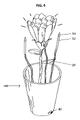
- FIG. 4 illustrates a second embodiment of the instant invention with a plurality of tips
- FIG. 5 shows a third embodiment of the device of the instant invention employing an optical fiber.
- the device of the instant invention functions by placing a light source comprising a penetrating tip inside the core of the object to be illuminated.
- the lighting and positioning means must not detract from the overall beauty of the flower and must not cause damage to the flower such that the life of the bloom is significantly shortened.
- the device must also be of a size and weight that does not cause the flower or the flower stem to deform significantly. Further, the device can be of such a size that it could be used in flowers or flower arrangements in which the flower stem is very short, such as in a corsage or boutonniere.
- FIGS. 1 , 1 a and 1 b One embodiment of the device of the instant invention 100 , FIGS. 1 , 1 a and 1 b , comprises case 11 which is attached to tube 12 .
- the distal end of tube 12 is attached to light source 13 which is contained in penetrating tip 14 .
- a power source such as a battery 17 .
- a first terminal of the power source is electrically connected via spring contact 18 to tube 12
- a second terminal of the power source is electrically connected to an electric wire 30 , which runs inside the hollow tube 12 .
- a resistor 19 may be employed in series fashion in this circuit to limit current to light source 13 .
- Light source 13 may be an LED, incandescent lamp or any other suitable source. Now referring to FIG.
- first contact of light source 13 is electrically connected to the distal end of tube 12 , typically by soldering or other suitable method of bonding.
- a second contact of light source 13 is electrically connected to the free end of electric wire 30 thereby completing the circuit.
- Tube 12 may comprise a “stepped” end to facilitate bonding of light source 13 to tube 12 while permitting the electric wire to be routed and bonded to the second contact of light source 13 .
- Pull-tab 15 which may be a strip of plastic, or other electrical insulator serves as a switch to power the device on. Pull-tab 15 may be placed between the batteries or other electrical contacts of the circuit as illustrated in FIG. 1 a . When pull-tab 15 is removed, the electrical circuit is completed and light source 13 is activated. Other known methods of switching the circuit on and off are anticipated and deemed to be within the scope of the instant invention.
- FIG. 1 c illustrates an alternate embodiment in which the penetrating tip 14 comprises a miniature LED or other light source, which light source, is of an appropriate size and shape to function as a penetrating tip.
- penetrating tip, 14 is inserted into the flower in or near the receptacle, 23 portion of the flower. This portion of the flower is situated between the peduncle and the calyx. If the receptacle is particularly tough or woody, penetrating tip 14 may be inserted directly into the petals 24 just above the upper portion of the receptacle. Case 11 is then manipulated so that penetrating tip 14 is positioned near the center of the flower or elsewhere as may be desired, e.g., within the corolla as illustrated in FIG. 2 .
- tube 12 is fabricated from a 1/16 inch outside diameter brass tube and penetrating tip 14 was produced from clear acrylic plastic. Any tube and tip materials may be employed in any manner of size and shape so long as they meet the needs of the instant invention.
- Penetrating tip 14 may be attached to the distal end of tube 12 by means of clear epoxy adhesive or any other suitable method. Penetrating tip 14 is preferably hollow to fit over light source 13 and end of tube 12 . Case 11 may be designed to resemble a leaf 25 or otherwise camouflaged so that it may be hidden in a flower arrangement.
- the capillary process which conveys these nutrients to the flower, not be significantly disturbed, otherwise the “life” of the flower will be compromised.
- the fibers and cellular structures which form part of this nutrient supply system, are oriented longitudinally with respect to the growth direction of the plant. Evidence of this may be found by the manner in which a flower stem will split along its length. To minimize damage to the flower it is desired to sever as few of the capillaries as possible. This may be achieved by using a small penetrating tip 14 to split the flower at the desired point of insertion. Splitting of the flower is preferred as opposed to perforation.
- Penetrating tip 14 may comprise a sharpened tip for this purpose.
- An attachment means 16 in the form of a clip or tie may be employed to maintain relative position of flower illumination device 100 relative to flower 200 .
- florist's tape may be employed for this purpose.
- the overall illumination effect is dependent on the exact nature of the flower to be illuminated as well as the light emitting properties of light source 13 .
- a rose or carnation will provide a different look when lighted than an orchid.
- the light source may be directly visible if viewed from above the flower.
- the flower glows from the outside and appears to have a “bright star” inside of it.
- the light emitted from the light source may comprise any color or combination of colors as may be desired.
- the apparent color of the item that is illuminated for example, a white rose, is a function of not only the color of the item but also the light source. It is anticipated that the light source may be capable of generating a plurality of colors such as may be generated by a multicolored LED which colors may be controlled by an electronic circuit. Further, the light source may be steady or caused to flash or pulse in an interesting manner.
- case 11 may be located a considerable distance from penetrating tip 14 such as in a vase containing a bouquet of flowers. Case 11 may be incorporated into the vase or even made integral to the vase which includes an on-off switch 40 , as illustrated in FIG. 4 . In this arrangement, the length of the penetrating tip may be extended somewhat to form a handle portion and to assist the user in piercing of the flower and manipulation of light source 13 within the flower.
- a third embodiment of the invention employs a light conducting member such as an optical fiber 51 to transmit light from a light source integral to case 11 to penetrating tip 14 .
- a light conducting member such as an optical fiber 51 to transmit light from a light source integral to case 11 to penetrating tip 14 .
- penetrating tip 14 may be integral to optical fiber 51 .
- the device may also be used to provide internal illumination of other products such as fruits or vegetables, for example, lemon, lime, or pineapple slices as may be served with tropical drinks.
- the device may be inserted into an olive or a cherry and served with a beverage.
- the device can be inserted into soft cheeses, breads and the like as may be desired to create glowing appetizers.
Abstract
Description
Claims (11)
Priority Applications (1)
| Application Number | Priority Date | Filing Date | Title |
|---|---|---|---|
| US11/076,671 US7278752B2 (en) | 2005-03-09 | 2005-03-09 | Device for providing internal illumination of live flowers and other products |
Applications Claiming Priority (1)
| Application Number | Priority Date | Filing Date | Title |
|---|---|---|---|
| US11/076,671 US7278752B2 (en) | 2005-03-09 | 2005-03-09 | Device for providing internal illumination of live flowers and other products |
Publications (2)
| Publication Number | Publication Date |
|---|---|
| US20060203474A1 US20060203474A1 (en) | 2006-09-14 |
| US7278752B2 true US7278752B2 (en) | 2007-10-09 |
Family
ID=36970640
Family Applications (1)
| Application Number | Title | Priority Date | Filing Date |
|---|---|---|---|
| US11/076,671 Expired - Fee Related US7278752B2 (en) | 2005-03-09 | 2005-03-09 | Device for providing internal illumination of live flowers and other products |
Country Status (1)
| Country | Link |
|---|---|
| US (1) | US7278752B2 (en) |
Cited By (1)
| Publication number | Priority date | Publication date | Assignee | Title |
|---|---|---|---|---|
| US20090154145A1 (en) * | 2007-06-19 | 2009-06-18 | Donald Nevin | LED illuminated tool |
Families Citing this family (1)
| Publication number | Priority date | Publication date | Assignee | Title |
|---|---|---|---|---|
| WO2016069884A2 (en) * | 2014-10-29 | 2016-05-06 | Altria Client Services Llc | E-vaping section for an e-vaping device |
Citations (27)
| Publication number | Priority date | Publication date | Assignee | Title |
|---|---|---|---|---|
| US2186143A (en) * | 1939-03-09 | 1940-01-09 | Edwin A Neugass | Illuminator |
| US3004140A (en) * | 1957-10-30 | 1961-10-10 | Cyril R Gomes | Illuminated pen or pencil |
| US3431410A (en) | 1966-07-13 | 1969-03-04 | Donner Electronics Inc | Ornamental display |
| US3455622A (en) | 1964-06-29 | 1969-07-15 | George D Cooper | Lighting device for transmitting visible radiant energies to inaccessible places |
| US3624385A (en) | 1970-04-09 | 1971-11-30 | Poly Optics | Ornamental illumination device and adapter |
| US4170036A (en) | 1978-08-07 | 1979-10-02 | Howard Sussel | Article of jewelry with flashing diode |
| US4215462A (en) | 1978-12-04 | 1980-08-05 | Fernandez Emile C | Method of making a translucent optical diffuser for a lamp |
| US4325110A (en) | 1980-03-13 | 1982-04-13 | Tang Woei S | Vase-type illuminative device |
| US4399493A (en) | 1981-12-30 | 1983-08-16 | Nihon Dennetsu Co., Ltd. | Illuminated artificial flower ornament |
| US4551129A (en) * | 1983-04-08 | 1985-11-05 | Coleman D Jackson | Technique and apparatus for intraocular and microsurgery including lighter-irrigator hypodermic tube |
| US4616304A (en) | 1984-10-15 | 1986-10-07 | Kohorn H Von | Illuminating device |
| US4617561A (en) * | 1985-03-11 | 1986-10-14 | Second Chance Systems, Inc. | Emergency light and smoke alarm system |
| US4626968A (en) | 1984-10-15 | 1986-12-02 | Kohorn H Von | Device for illuminating centripetally viewed three-dimensional objects in wet locations |
| US4646209A (en) | 1984-04-09 | 1987-02-24 | Paul Jansen | Illuminated standing support for plant and flower boxes and other recipients |
| US4866580A (en) | 1988-04-25 | 1989-09-12 | Carol Blackerby | Ornamental lighting device |
| US5063485A (en) | 1989-12-18 | 1991-11-05 | Harris Edward H | Illuminated artificial flowers |
| US5131775A (en) * | 1991-08-02 | 1992-07-21 | Chen Chuang Yi | Retractable pen with illumination means |
| US5253149A (en) | 1993-01-21 | 1993-10-12 | Ostema Loren D | Illuminated jewelry |
| US5497307A (en) | 1995-06-28 | 1996-03-05 | Bae; Tae H. | Illuminating jewelry |
| US5508901A (en) | 1995-03-20 | 1996-04-16 | Kuo; Ming-Shish | Multi-colored light-emitting flower decoration |
| US5947582A (en) | 1998-08-07 | 1999-09-07 | Shining Blick Enterprises Co., Ltd. | Flower-shaped ornamental lamp |
| US5951140A (en) | 1997-06-11 | 1999-09-14 | Live Wire Enterprises, Inc. | Display with flexible electroluminescent connector |
| US6076940A (en) | 1998-07-16 | 2000-06-20 | Sanford, Jr.; Sammie J. | Planter light accessory |
| US6296364B1 (en) | 1999-11-09 | 2001-10-02 | Big Easy Beads, Llc | Lighted bead necklace |
| US20030035291A1 (en) | 2001-08-14 | 2003-02-20 | Jensen Bradford B. | Imitation candle |
| US20040085758A1 (en) | 2002-10-31 | 2004-05-06 | David Deng | Electric decorative flower |
| US6874188B2 (en) * | 2001-08-13 | 2005-04-05 | Wampum | Multi-tasking utility tool |
Family Cites Families (2)
| Publication number | Priority date | Publication date | Assignee | Title |
|---|---|---|---|---|
| US6254247B1 (en) * | 1999-01-14 | 2001-07-03 | Redgate Industries, Inc. | Illuminable containers and method |
| US6874908B2 (en) * | 2002-05-13 | 2005-04-05 | Streamlight, Inc. | Flexible bendable flashlight |
-
2005
- 2005-03-09 US US11/076,671 patent/US7278752B2/en not_active Expired - Fee Related
Patent Citations (27)
| Publication number | Priority date | Publication date | Assignee | Title |
|---|---|---|---|---|
| US2186143A (en) * | 1939-03-09 | 1940-01-09 | Edwin A Neugass | Illuminator |
| US3004140A (en) * | 1957-10-30 | 1961-10-10 | Cyril R Gomes | Illuminated pen or pencil |
| US3455622A (en) | 1964-06-29 | 1969-07-15 | George D Cooper | Lighting device for transmitting visible radiant energies to inaccessible places |
| US3431410A (en) | 1966-07-13 | 1969-03-04 | Donner Electronics Inc | Ornamental display |
| US3624385A (en) | 1970-04-09 | 1971-11-30 | Poly Optics | Ornamental illumination device and adapter |
| US4170036A (en) | 1978-08-07 | 1979-10-02 | Howard Sussel | Article of jewelry with flashing diode |
| US4215462A (en) | 1978-12-04 | 1980-08-05 | Fernandez Emile C | Method of making a translucent optical diffuser for a lamp |
| US4325110A (en) | 1980-03-13 | 1982-04-13 | Tang Woei S | Vase-type illuminative device |
| US4399493A (en) | 1981-12-30 | 1983-08-16 | Nihon Dennetsu Co., Ltd. | Illuminated artificial flower ornament |
| US4551129A (en) * | 1983-04-08 | 1985-11-05 | Coleman D Jackson | Technique and apparatus for intraocular and microsurgery including lighter-irrigator hypodermic tube |
| US4646209A (en) | 1984-04-09 | 1987-02-24 | Paul Jansen | Illuminated standing support for plant and flower boxes and other recipients |
| US4626968A (en) | 1984-10-15 | 1986-12-02 | Kohorn H Von | Device for illuminating centripetally viewed three-dimensional objects in wet locations |
| US4616304A (en) | 1984-10-15 | 1986-10-07 | Kohorn H Von | Illuminating device |
| US4617561A (en) * | 1985-03-11 | 1986-10-14 | Second Chance Systems, Inc. | Emergency light and smoke alarm system |
| US4866580A (en) | 1988-04-25 | 1989-09-12 | Carol Blackerby | Ornamental lighting device |
| US5063485A (en) | 1989-12-18 | 1991-11-05 | Harris Edward H | Illuminated artificial flowers |
| US5131775A (en) * | 1991-08-02 | 1992-07-21 | Chen Chuang Yi | Retractable pen with illumination means |
| US5253149A (en) | 1993-01-21 | 1993-10-12 | Ostema Loren D | Illuminated jewelry |
| US5508901A (en) | 1995-03-20 | 1996-04-16 | Kuo; Ming-Shish | Multi-colored light-emitting flower decoration |
| US5497307A (en) | 1995-06-28 | 1996-03-05 | Bae; Tae H. | Illuminating jewelry |
| US5951140A (en) | 1997-06-11 | 1999-09-14 | Live Wire Enterprises, Inc. | Display with flexible electroluminescent connector |
| US6076940A (en) | 1998-07-16 | 2000-06-20 | Sanford, Jr.; Sammie J. | Planter light accessory |
| US5947582A (en) | 1998-08-07 | 1999-09-07 | Shining Blick Enterprises Co., Ltd. | Flower-shaped ornamental lamp |
| US6296364B1 (en) | 1999-11-09 | 2001-10-02 | Big Easy Beads, Llc | Lighted bead necklace |
| US6874188B2 (en) * | 2001-08-13 | 2005-04-05 | Wampum | Multi-tasking utility tool |
| US20030035291A1 (en) | 2001-08-14 | 2003-02-20 | Jensen Bradford B. | Imitation candle |
| US20040085758A1 (en) | 2002-10-31 | 2004-05-06 | David Deng | Electric decorative flower |
Cited By (2)
| Publication number | Priority date | Publication date | Assignee | Title |
|---|---|---|---|---|
| US20090154145A1 (en) * | 2007-06-19 | 2009-06-18 | Donald Nevin | LED illuminated tool |
| US8118444B2 (en) * | 2007-06-19 | 2012-02-21 | Donald Nevin | LED illuminated tool |
Also Published As
| Publication number | Publication date |
|---|---|
| US20060203474A1 (en) | 2006-09-14 |
Similar Documents
| Publication | Publication Date | Title |
|---|---|---|
| US4833580A (en) | Illuminated decorative ornament | |
| US7237922B2 (en) | Pumpkin illumination stake | |
| GB2425169A (en) | Colour mixing decoration with optic fibre | |
| US6908206B1 (en) | Illuminated articles | |
| US6513945B1 (en) | Decorative illuminated pumpkin stems | |
| US7575356B1 (en) | Birthday cake costume jewelry | |
| US7278752B2 (en) | Device for providing internal illumination of live flowers and other products | |
| US6145999A (en) | Battery device | |
| US20110051406A1 (en) | Star lite | |
| US7178363B2 (en) | Illuminated and fragrance-releasing jewelry device | |
| JP2007012501A (en) | Inclination sensing type light emitting device | |
| US20190014872A1 (en) | Jewelry Illumination System | |
| US7213957B1 (en) | Lighted Christmas star ornament apparatus | |
| US20140321152A1 (en) | Light up centerpiece | |
| JP2007070760A (en) | Luminous material produced by using optical fiber and artificial flower | |
| JP3222340U (en) | Clutch type wedding bouquet | |
| US20020181248A1 (en) | Lighting display toy | |
| US20050157485A1 (en) | Decorative lighting device with windmill | |
| EP0290690A1 (en) | Optical fibre ornamented light set | |
| US20030179590A1 (en) | Decorative illuminated pumpkin stems | |
| JP3168388U (en) | Lotus flower lamp for funeral | |
| JP3245113U (en) | glowing rose kit | |
| US20060223016A1 (en) | Candle finial | |
| KR20130041489A (en) | Flower support | |
| JP2001118401A (en) | Illumination device with light-emitting body |
Legal Events
| Date | Code | Title | Description |
|---|---|---|---|
| AS | Assignment |
Owner name: OMNIGLOW CORPORATION, MASSACHUSETTS Free format text: ASSIGNMENT OF ASSIGNORS INTEREST;ASSIGNORS:PALMER, WILLIAM R.;PALMER, STEPHEN L.;PALMER, ROBERT N.;REEL/FRAME:016393/0248 Effective date: 20050202 |
|
| AS | Assignment |
Owner name: CYALUME TECHNOLOGIES, INC., MASSACHUSETTS Free format text: MERGER;ASSIGNOR:OMNIGLOW CORPORATION;REEL/FRAME:017168/0366 Effective date: 20060123 |
|
| AS | Assignment |
Owner name: THE BANK OF NEW YORK, NEW YORK Free format text: SECURITY AGREEMENT;ASSIGNOR:CYALUME TECHNOLOGIES, INC.;REEL/FRAME:017183/0525 Effective date: 20060123 |
|
| AS | Assignment |
Owner name: CHEMICAL LIGHT INC., ILLINOIS Free format text: ASSIGNMENT OF ASSIGNORS INTEREST;ASSIGNOR:OMNIGLOW, LLC;REEL/FRAME:019783/0912 Effective date: 20070904 Owner name: OMNIGLOW, LLC, MASSACHUSETTS Free format text: ASSIGNMENT OF ASSIGNORS INTEREST;ASSIGNOR:OMNIGLOW CORPORATION (CYALUME TECHNOLOGIES, INC.);REEL/FRAME:019783/0945 Effective date: 20070830 |
|
| STCF | Information on status: patent grant |
Free format text: PATENTED CASE |
|
| AS | Assignment |
Owner name: THE BANK OF NEW YORK, AS COLLATERAL AGENT, NEW YOR Free format text: INTELLECTUAL PROPERTY SECURITY AGREEMENT (SECOND LIEN);ASSIGNOR:CYALUME TECHNOLOGIES, INC.;REEL/FRAME:021603/0467 Effective date: 20060123 |
|
| AS | Assignment |
Owner name: FORTRESS CREDIT CORP., AS COLLATERAL AGENT, NEW YO Free format text: RESIGNATION OF THE BANK OF NEW YORK AND APPOINTMENT OF FORTRESS CREDIT CORP AT REEL/FRAME NOS. 017176/0745, 017183/0525, 021603/0291, 021612/0292, AND 021603/0291;ASSIGNOR:THE BANK OF NEW YORK;REEL/FRAME:021691/0525 Effective date: 20070522 |
|
| FPAY | Fee payment |
Year of fee payment: 4 |
|
| FPAY | Fee payment |
Year of fee payment: 8 |
|
| FEPP | Fee payment procedure |
Free format text: MAINTENANCE FEE REMINDER MAILED (ORIGINAL EVENT CODE: REM.); ENTITY STATUS OF PATENT OWNER: SMALL ENTITY |
|
| LAPS | Lapse for failure to pay maintenance fees |
Free format text: PATENT EXPIRED FOR FAILURE TO PAY MAINTENANCE FEES (ORIGINAL EVENT CODE: EXP.); ENTITY STATUS OF PATENT OWNER: SMALL ENTITY |
|
| STCH | Information on status: patent discontinuation |
Free format text: PATENT EXPIRED DUE TO NONPAYMENT OF MAINTENANCE FEES UNDER 37 CFR 1.362 |
|
| FP | Lapsed due to failure to pay maintenance fee |
Effective date: 20191009 |