US7280254B2 - Method for maintaining uniform spatial frequency over a dataglyph block - Google Patents
Method for maintaining uniform spatial frequency over a dataglyph block Download PDFInfo
- Publication number
- US7280254B2 US7280254B2 US10/373,972 US37397203A US7280254B2 US 7280254 B2 US7280254 B2 US 7280254B2 US 37397203 A US37397203 A US 37397203A US 7280254 B2 US7280254 B2 US 7280254B2
- Authority
- US
- United States
- Prior art keywords
- glyph
- code
- image space
- glyphs
- image
- Prior art date
- Legal status (The legal status is an assumption and is not a legal conclusion. Google has not performed a legal analysis and makes no representation as to the accuracy of the status listed.)
- Expired - Fee Related, expires
Links
Images


Classifications
-
- H—ELECTRICITY
- H04—ELECTRIC COMMUNICATION TECHNIQUE
- H04N—PICTORIAL COMMUNICATION, e.g. TELEVISION
- H04N1/00—Scanning, transmission or reproduction of documents or the like, e.g. facsimile transmission; Details thereof
- H04N1/40—Picture signal circuits
- H04N1/405—Halftoning, i.e. converting the picture signal of a continuous-tone original into a corresponding signal showing only two levels
-
- G—PHYSICS
- G06—COMPUTING; CALCULATING OR COUNTING
- G06T—IMAGE DATA PROCESSING OR GENERATION, IN GENERAL
- G06T2201/00—General purpose image data processing
- G06T2201/005—Image watermarking
- G06T2201/0065—Extraction of an embedded watermark; Reliable detection
Definitions
- This invention relates generally to devices and methods for embedding machine-readable digital data as self-clocking glyph shape codes, and, more particularly, to devices and methods for producing glyph shape codes such that the embedded digital data is unobtrusive.
- machine readable digital data can be recorded by writing two dimensional marks on a recording medium in accordance with a pattern which encodes the data either by the presence or absence of marks at a sequence of spatial locations or by the presence or absence of mark related transitions at such locations.
- the bar-like codes which others have proposed for recording digital data on paper utilize that type of encoding. See U.S. Pat. No. 4,692,603 titled “Optical Reader for Printed Bit-Encoded Data and Method of Reading Same,” U.S. Pat. No. 4,728,783 and U.S. Pat. No. 4,754,127 on “Method and Apparatus for Transforming Digitally Encoded Data into Printed Data Strips,” and U.S. Pat. No.
- Glyph shape codes have the advantage that they can be designed to have a relatively uniform appearance.
- a simple glyph shape code suitably is composed of small slash-like marks that are tilted to the right or left at, say, ⁇ 45 degrees for encoding 1's and 0's, respectively.
- the more or less uniformly gray appearance of such a code may be aesthetically objectionable, and may cause the tone of the image to change upon tilting of the glyph codes.
- a regular glyph block especially in a glyph tone image, shows an apparent artifact if four neighboring cells form an empty diamond shape.
- the size of a diamond is twice as large as the average spatial frequency of the whole block, it becomes visually noticeable in the image.
- a method for reducing the obtrusiveness of artifacts appearing in a glyph shape code image space.
- the method includes encoding digital data values as a glyph shape code, such that the shape code is composed of glyphs having shapes that encode digital data values. Each distinct data value that is encoded is represented by the shape of a glyph, and these glyphs are spatially distributed in a bitmap image space.
- the bitmap image space is analyzed to determine the presence of artifacts within the bitmap image space, and a raster image is generated in which at least a single dot is placed within at least one of the artifacts in the image space.
- a system for reducing the obtrusiveness of artifacts appearing in a glyph shape code image space.
- the system includes an input device for providing a bitmap image and a processor for executing control instructions and image editing and manipulation instructions.
- an encoder for encoding digital data values as a glyph shape code, in which the code is composed of glyphs having shapes that encode digital data values, such that each distinct data value that is encoded is represented by the shape of a respective glyph.
- the processor also analyzes the bitmap image space to determine the presence of artifacts within the image.
- the image is then manipulated to create a bitmapped image file in which at least one dot is placed within at least one of the artifacts.
- the system also includes a main memory, a mass memory and a printer for mapping the digital values of the bitmapped image file into the spatially corresponding pixels of the image it prints on a recording medium.
- an article of manufacture for performing a method for reducing the obtrusiveness of artifacts appearing in a glyph shape code image space.
- the article of manufacture includes a computer usable medium in which computer readable program code is embodied.
- the program code When the program code is executed by a computer, the computer encodes digital data values as a glyph shape code, such that the shape code is composed of glyphs having shapes that encode digital data values. Each distinct data value that is encoded is represented by the shape of a glyph, and these glyphs are spatially distributed in a bitmap image space.
- the bitmap image space is analyzed to determine the presence of artifacts within the bitmap image space, and a raster image is generated in which at least a single dot is placed within at least one of the artifacts in the image space.
- FIG. 1 is a functional block diagram of an electronic document processing system for carrying out and taking advantage of the various aspects of the present invention
- FIG. 2 is a coding diagram for illustrating the bit encoding of binary data in a rotationally invariant glyph shape code
- FIG. 3 illustrates a portion of a DataGlyph® image having artifacts
- FIG. 4 is a high-level functional block diagram of one embodiment of a method for reducing the obtrusiveness of glyph codes forming a diamond shape
- FIG. 5 is a flowchart of one embodiment of a method for reducing the obtrusiveness of glyph codes forming a diamond shape according to the embodiment of FIG. 4 ;
- FIG. 6 illustrates the glyph code pattern embodiments according to the flowchart of FIG. 5 ;
- FIG. 7 illustrates sample embodiments of tables utilized as indicated in the flowchart of FIG. 5 ;
- FIG. 8 illustrates the reduction of visibility of artifacts in a DataGlyph image in accordance with one embodiment of the subject invention
- FIG. 9 illustrates the reduction of visibility of artifacts in a DataGlyph image according to another embodiment of the subject invention.
- FIG. 10 illustrates a typical gray scale image
- FIG. 11 shows the gray scale image of FIG. 10 rendered as a GlyphTone image
- FIG. 12 is a high-level functional block diagram of another embodiment of a method for reducing the obtrusiveness of glyph codes forming a diamond shape in GlyphTone images;
- FIG. 13 is a flowchart of the method for reducing the obtrusiveness of glyph codes forming a diamond shape according to the embodiment of FIG. 12 ;
- FIG. 14 illustrates sample embodiments of halftone generators utilized as indicated in the flowchart of FIG. 13 ;
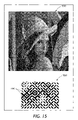
- FIG. 15 shows the gray scale image of FIG. 10 rendered as a GlyphTone image in which artifact visibility is reduced according to the embodiment of FIG. 13 .
- the document processing system 100 illustrates a typical environment for embodiments disclosed herein.
- the document processing system 100 comprises a digital processor 110 having a main memory 130 and a mass memory 140 , an input device 150 for providing digital representations of selected hardcopy documents into the processor 110 , and a printer 120 for printing hardcopy renderings of selected ones of the files that are listed on the file directory (not shown) of the processor 110 .
- the system may include a user interface 160 for enabling a user to interact with the processor 110 , the input device 150 , and the printer 120 .
- the user interface 160 collectively represents the input devices through which the user enters control instructions for the input device 150 and for the printer 120 , as well as the image editing and manipulation instructions for the processor 110 . Additionally, the interface 160 represents the output devices through which the user receives feedback with respect to the actions that are taken in response to the instructions that are entered by the user or otherwise, such as under program control.
- the user interface 160 generally includes a keyboard or the like for entering use instructions, a monitor for giving the user a view of the process that is being performed by the processor 110 , and a cursor controller for enabling the user to move a cursor for making selections from and/or for entering data into a process that is being displayed by the monitor (none of these conventional components is shown).
- the illustrated document processing system 100 is centralized, so it has been simplified by assuming that all control instructions and all image editing and manipulation instructions are executed by the processor 110 under program control. In practice, however, the execution of these instructions may be handled by several different processors, some or all of which may have their own main memory and even their own mass memory. Likewise, either or both of the input device 150 and the printer 120 may have its own user interface, as indicated by the dashed lines 155 and 165 , respectively. Indeed, it will be evident that the document processing system 100 could be reconfigured to have a distributed architecture to operate with a remote input scanner and/or a remote printer (not shown). Data could be transferred from and to such remote scanner and printer terminals via dedicated communication links or switched communication networks (also not shown).
- the printer 120 generally is a so-called bitmap printer for mapping the digital values of a bitmapped image file into the spatially corresponding pixels of the image it prints on a suitable recording medium, such as plain paper.
- the processor 110 may be configured to manipulate and store bitmapped image files and to transfer such files on demand to the printer 120 .
- the processor 110 may include a PDL (page description language) driver 112 for transferring to the printer 120 PDL descriptions of the electronic document files that are selected for printing.
- the printer 120 is illustrated as having a PDL decomposer 170 for decomposing such PDL descriptions to produce corresponding bitmapped image files. Still other types of printers and processor/printer interfaces will suggest themselves, but it will be assumed for purposes of the following discussion that the printer 120 is a bitmap printer that receives PDL files from the processor 110 .
- a glyph encoder 114 for causing the printer 120 to print machine-readable digital data glyphs on the recording medium, either alone or in juxtaposition with human readable information.
- the glyph encoder 114 may be co-located with the processor 110 for inserting glyph encodings into the electronic document files prior to the translation of such files into PDL descriptions. But, for other applications, it may be necessary or desirable to have the glyph encoder 114 insert the glyph encodings into the raster formatted bitmapped image file that is provided for the printer 120 .
- PDL descriptions of glyph shape encoded may take several different forms, including encapsulated bitmap representations of the code in which such data is encoded, font descriptions and layout locations for bitmap representations of the individual encoded glyph shapes (assuming that such bitmaps exist on or are down loadable to the font directory of the printer 120 ), and bit-by-bit descriptions of the bitmaps for the encoded glyph shapes.
- each of the printed glyphs 210 is defined by the pixel pattern that is printed within a generally rectangular, two dimensional, array 220 of pixel positions (referred to hereinafter as a “glyph cell” or as a “data cell”).
- These glyph defining data cells 220 typically are tiled onto the recording medium in accordance with a predetermined spatial formatting rule which causes the glyph encodings 210 for successive data values to be spatially distributed in accordance with a predefined template or patter.
- the data cell 220 containing the glyph encodings 210 for successive data values suitably are printed on the recording medium in accordance with a regular and repeating logical data block formatting rule, such that the printed data cells are spatially organized in a two dimensional array of logical blocks of predetermined size, such as a 16 cell ⁇ 16 cell logical block format.
- Glyph shape encoding clearly permits many different implementations, some of which are suitable for the encoding of single bit digital values and other of which are suitable for the encoding of multi-bit values.
- single bit values (“1” and “0”) conveniently are encoded by printing elongated, multi-pixel glyphs, each of which is composed of a predetermined number of adjacent “ON” (say, black) pixels which align along an axis that is inclined at an angle of about +45° or ⁇ 45° from the transverse axis of the recording medium depending on whether the data value encoded therein is a “1” or a “0”.
- Such glyphs are examples of so-called “rotationally variant” glyphs because they can be mapped onto each other merely by rotational operations. They also are examples of glyphs, which are readily discriminable, even in the presence of significant distortion and image degradation, because they do not tend to degrade into a common shape.
- glyph shape encoding may be modified to reduce the obtrusiveness of glyph block patterns containing diamonds.
- data is glyph shape encoded at 410 and the encoded glyph shapes are checked by the system to identify the occurrence of diamond shapes at 420 .
- the encoded data glyph shapes then are converted into a raster format at 430 .
- the raster formatted glyph shapes are modified to include clustered dots within the diamond shapes at 430 .
- the resulting image may then be printed on a suitable recording medium, such as plain paper, by a bitmap printer.
- FIGS. 5 through 7 the method for reducing the obtrusiveness of artifacts in glyph images is presented in greater detail.
- information to be preserved in glyphs is encoded in blocks of “0”'s and “1”'s.
- N which represents the scan line denominator, is initially assigned a value of “1”.
- the N th and (N+1) th scanlines are examined for patterns that form diamonds within the total glyph image at 530 , for example
- the processor If the (N+1) th scan line is not the last one, the processor returns to repeat step 530 until the final scan line has been evaluated.
- the diamond artifact is identified through a top-down, dual scan-line approach, it will be appreciated by those skilled in the art that numerous other approaches may be beneficially employed.
- the processor then renders “0” through “7” in varying patterns according to the patterns entered on either Table 1 or Table 2 shown in FIG. 7 . As may be appreciated from Tables 1 and 2, various embodiments of dots in glyph shapes are possible. Table 1 illustrates glyph patterns for a first embodiment, which result in dispersed dots placed within the diamond configurations, as shown in FIG. 6 at 615 , 625 , 635 , and 645 .
- Table 2 illustrates glyph patterns for a second embodiment, which result in clustered dots placed within the diamond configurations, as discussed hereinbelow with reference to FIG. 8 .
- alternate glyph patterns could also be beneficially employed to the same purpose, all of which are contemplated by the spirit and scope of the claims herein. For example, fewer dots could be placed in the cells of the artifact; even a single dot in one of the glyph cells would be sufficient for providing a more uniform spatial frequency in the image.
- a raster converter then creates an image at 570 , which is transmitted to a printing device at 580 .
- FIG. 8 the reduction in obtrusiveness of diamonds in a glyph image is shown with the embodiment of Table 2 from FIG. 7 .
- glyph block rendering 810 a cluster of pixels, in the form of a clustered dot, have been placed in each diamond 820 to bring the spatial frequency in the neighborhood to a similar range as the rest of the image.
- a portion of the glyph block rendering is enlarged at 830 such that clustered dots 840 can be seen more clearly. Although typically there would be at least four dots in the cluster, it will be appreciated that this number could vary.
- Placement of the pixels in a clustered dot provides a solution that is more stably reproduced by printing engines. Some print engines, depending on their operational speed, may skip single pixel dots.
- glyph block image 910 includes dispersed dots in each four-stroke diamond 920 .
- each dot 940 may be a single pixel or a cluster of pixels. While this embodiment meets the requirement of a “quiet zone” and is potentially easier to decode, if a dispersed dot consists of a single pixel, it may not be printed by some print engines.
- Halftoning is a well known and widely utilized technique for imparting a grayscale appearance to dual tone renderings of variably shaded monochromatic images (e.g., black and white images), and to dual tone color separations of variably shaded polychromatic images. It originated as an optical analog process for imparting a grayscale appearance to dual tone reproductions of continuous tone monochromatic images, but it since has been extended to provide digital halftoning processes that can be utilized by digital document processors for imparting a grayscale appearance to dual tone representation of variably shaded, scanned-in digitized images and to dual tone representations of variably shaded, computer generated synthetic images.
- digitally defined images may be monochromatic or polychromatic, so it is to be understood that digital halftoning can be applied for imparting a grayscale appearance to printed and displayed renderings of monochromatic and polychromatic images.
- Polychromatic images typically are halftoned by halftoning each of the color separations that are provided for rendering such images.
- Glyph states can be generalized to distinguishable halftone cell patterns of equal gray or color value, especially rotations of patterns without circular symmetry as taught in Tow (cited hereinabove). Such an image may also be referred to as a GlyphTone image.
- the use of glyph blocks to render halftone images is generally visually non-intrusive, but an artifact, a visual effect (usually considered a defect) introduced into a digital image that does not correspond to the image scanned, may appear if four neighboring cells form an empty diamond shape.
- a grayscale image instead of having a uniform appearance, numerous diamonds formed by four strokes in the rendering result in an uneven image appearance, due to an uneven spatial frequency.
- FIG. 10 shows a standard gray scale pictorial halftone 1000 .
- a halftone image is one in which combinations of dots are used to create an impression of grays or colors by grouping and density. For example, the eye will see shades of gray in black dots on a white background. Where the dots are large, dense and possibly overlapping, the eye sees dark gray or black; where the dots are small and sparse, the eye sees light gray or white.
- This image can be contrasted with the same pictorial halftone, rendered in glyph blocks in FIG. 11 .
- the visual effect is pictorial, and the individual cells are imperceptible. However, in the closer view shown in FIG.
- image 1100 the artifacts formed by four-stroke diamonds in image 1100 are noticeable throughout the figure, but are particularly prominent at the model's right eye. This portion of image 1100 has been enlarged at 1120 to illustrate the formation of glyph block diamonds 1130 in the right eye region.
- glyph shape encoding may be modified to reduce the obtrusiveness of glyph block patterns containing diamonds in halftone images.
- data is glyph shape encoded at 1210 and the encoded glyph shapes are checked by the system to identify the occurrence of diamond shapes at 1220 .
- Gray scale or color image 1230 is provided to the processor with the encoded data glyph shapes and is converted into a raster format and glyph shapes are modified to include clustered dots within the diamond shapes at 1240 . It will be appreciated that, although it is desirable to do the raster conversion and dot placement simultaneously, dot placement may be performed after the raster conversion as a post processing step. The resulting image may then be printed on a suitable recording medium, such as plain paper, by a bitmap printer.
- FIG. 13 the method for reducing the obtrusiveness of artifacts in halftone glyph images is presented in greater detail.
- information to be preserved in glyphs is encoded in blocks of “0”'s and “1”'s.
- N which represents the scan line denominator, is initially assigned a value of “1”.
- the N th and (N+1) th scanlines are examined for patterns that form diamonds within the total glyph image at 1330 , for example
- the processor returns to repeat step 1330 until the final scan line has been evaluated.
- the diamond artifact is identified through a top-down, dual scan-line approach, it will be appreciated by those skilled in the art that numerous other approaches may be beneficially employed.
- a halftone generator is selected for each glyph cell based on the data value of 0-7 at 1360 .
- the chosen threshold arrays of N ⁇ N are tiled over the input gray scale or color image, with each threshold array covering an N ⁇ N area of the input image.
- a pixel is turned on in the output raster if and only if P ⁇ N 2 ⁇ T ( i,j ), Where T(i,j) is the value in the threshold array entry of the i-th row and the j-th column, and P is the intensity value of the pixel that corresponds to the threshold array entry, normalized to an interval between 0.0 and 1.0.
- the processor then renders “0” through “7” in varying patterns according to the sample patterns illustrated in FIG. 14 .
- the halftone generators at each glyph cell receive gray scale or color image 1370 and converts the gray scale or color image to a halftone image.
- alternate glyph patterns could also be beneficially employed to the same purpose, all of which are contemplated by the spirit and scope of the claims herein. For example, fewer dots could be placed in the cells of the artifact; even a single dot in one of the glyph cells would be sufficient for providing a more uniform spatial frequency in the image.
- a raster converter then creates an image at 1390 , which is transmitted to a printing device.
- FIG. 15 shows an example of the glyph block image according to FIG. 11 reproduced with glyph tone cells with clustered dots in each diamond.
- image 1510 it can be observed that the artifact at the right eye has been reduced and the overall image appearance is more uniform.
- Image 1530 shows an enlargement of the right eye portion of image 1510 , with clustered dots 1540 .
- code as used herein, or “program” as used herein, is any plurality of binary values or any executable, interpreted or compiled code which can be used by a computer or execution device to perform a task. This code or program can be written in any one of several known computer languages.
- a “computer”, as used herein, can mean any device which stores, processes, routes, manipulates, or performs like operation on data. It is to be understood, therefore, that this invention is not limited to the particular forms illustrated and that it is intended in the appended claims to embrace all alternatives, modifications, and variations which do not depart from the spirit and scope of this invention.
Abstract
Description
which are illustrated in
which conversion is illustrated in
which are illustrated in
which conversion is illustrated in
P·N 2 ≧T(i,j),
Where T(i,j) is the value in the threshold array entry of the i-th row and the j-th column, and P is the intensity value of the pixel that corresponds to the threshold array entry, normalized to an interval between 0.0 and 1.0. The processor then renders “0” through “7” in varying patterns according to the sample patterns illustrated in
Claims (22)
Priority Applications (2)
| Application Number | Priority Date | Filing Date | Title |
|---|---|---|---|
| US10/373,972 US7280254B2 (en) | 2003-02-25 | 2003-02-25 | Method for maintaining uniform spatial frequency over a dataglyph block |
| US11/973,118 US7813008B2 (en) | 2003-02-25 | 2007-10-05 | System and method for improving an appearance of a raster image comprising glyph shapes |
Applications Claiming Priority (1)
| Application Number | Priority Date | Filing Date | Title |
|---|---|---|---|
| US10/373,972 US7280254B2 (en) | 2003-02-25 | 2003-02-25 | Method for maintaining uniform spatial frequency over a dataglyph block |
Related Child Applications (1)
| Application Number | Title | Priority Date | Filing Date |
|---|---|---|---|
| US11/973,118 Continuation US7813008B2 (en) | 2003-02-25 | 2007-10-05 | System and method for improving an appearance of a raster image comprising glyph shapes |
Publications (2)
| Publication Number | Publication Date |
|---|---|
| US20040165219A1 US20040165219A1 (en) | 2004-08-26 |
| US7280254B2 true US7280254B2 (en) | 2007-10-09 |
Family
ID=32868774
Family Applications (2)
| Application Number | Title | Priority Date | Filing Date |
|---|---|---|---|
| US10/373,972 Expired - Fee Related US7280254B2 (en) | 2003-02-25 | 2003-02-25 | Method for maintaining uniform spatial frequency over a dataglyph block |
| US11/973,118 Expired - Fee Related US7813008B2 (en) | 2003-02-25 | 2007-10-05 | System and method for improving an appearance of a raster image comprising glyph shapes |
Family Applications After (1)
| Application Number | Title | Priority Date | Filing Date |
|---|---|---|---|
| US11/973,118 Expired - Fee Related US7813008B2 (en) | 2003-02-25 | 2007-10-05 | System and method for improving an appearance of a raster image comprising glyph shapes |
Country Status (1)
| Country | Link |
|---|---|
| US (2) | US7280254B2 (en) |
Cited By (2)
| Publication number | Priority date | Publication date | Assignee | Title |
|---|---|---|---|---|
| US20110063642A1 (en) * | 2008-04-02 | 2011-03-17 | Crossmedia Solution Gmbh & Co.Kg | Method for storing and reading data |
| US20220004831A1 (en) * | 2017-03-30 | 2022-01-06 | Orbid Limited | Method of Marking an Object, Method for Generating a Marker, Method for Generating a Marker Code, and Method for Authenticating an Object |
Families Citing this family (7)
| Publication number | Priority date | Publication date | Assignee | Title |
|---|---|---|---|---|
| US20030103246A1 (en) * | 2001-11-30 | 2003-06-05 | Eastman Kodak Company | System and method for providing unobtrusive human visible information on a print |
| US20050087610A1 (en) * | 2003-10-27 | 2005-04-28 | Adams Guy De W.B. | Visually significant marking in position encoded glyph carpets |
| ITMI20050824A1 (en) * | 2005-05-06 | 2006-11-07 | Secure Edge S R L | HIGH DENSITY TWO-DIMENSIONAL GRAPHIC CODE AND CODING SYSTEM AND DECODING SYSTEM BASED ON THIS CODE |
| US7471418B2 (en) * | 2005-06-02 | 2008-12-30 | Xerox Corporation | Image/document analysis tool and method for multi-station image forming device |
| US7823795B2 (en) * | 2007-04-02 | 2010-11-02 | International Business Machines Corporation | Pattern based elaboration of hierarchical L3GO designs |
| CA2737430C (en) * | 2008-09-16 | 2015-03-24 | National Printing Bureau, Incorporated Administrative Agency | Anti-counterfeit printed matter, method of manufacturing the same, and recording medium storing halftone dot data creation software |
| TWI676781B (en) * | 2018-08-17 | 2019-11-11 | 鑑微科技股份有限公司 | Three-dimensional scanning system |
Citations (7)
| Publication number | Priority date | Publication date | Assignee | Title |
|---|---|---|---|---|
| US5091966A (en) | 1990-07-31 | 1992-02-25 | Xerox Corporation | Adaptive scaling for decoding spatially periodic self-clocking glyph shape codes |
| US5128525A (en) * | 1990-07-31 | 1992-07-07 | Xerox Corporation | Convolution filtering for decoding self-clocking glyph shape codes |
| US5315098A (en) | 1990-12-27 | 1994-05-24 | Xerox Corporation | Methods and means for embedding machine readable digital data in halftone images |
| US5710636A (en) | 1995-06-05 | 1998-01-20 | Xerox Corporation | Method and apparatus for generating halftone images having human readable patterns formed therein |
| US5862255A (en) * | 1996-06-18 | 1999-01-19 | Xerox Corporation | Broad bandwidth image domain communication channel with symbol interference suppression |
| US6076738A (en) * | 1990-07-31 | 2000-06-20 | Xerox Corporation | Self-clocking glyph shape codes |
| US6641053B1 (en) * | 2002-10-16 | 2003-11-04 | Xerox Corp. | Foreground/background document processing with dataglyphs |
-
2003
- 2003-02-25 US US10/373,972 patent/US7280254B2/en not_active Expired - Fee Related
-
2007
- 2007-10-05 US US11/973,118 patent/US7813008B2/en not_active Expired - Fee Related
Patent Citations (7)
| Publication number | Priority date | Publication date | Assignee | Title |
|---|---|---|---|---|
| US5091966A (en) | 1990-07-31 | 1992-02-25 | Xerox Corporation | Adaptive scaling for decoding spatially periodic self-clocking glyph shape codes |
| US5128525A (en) * | 1990-07-31 | 1992-07-07 | Xerox Corporation | Convolution filtering for decoding self-clocking glyph shape codes |
| US6076738A (en) * | 1990-07-31 | 2000-06-20 | Xerox Corporation | Self-clocking glyph shape codes |
| US5315098A (en) | 1990-12-27 | 1994-05-24 | Xerox Corporation | Methods and means for embedding machine readable digital data in halftone images |
| US5710636A (en) | 1995-06-05 | 1998-01-20 | Xerox Corporation | Method and apparatus for generating halftone images having human readable patterns formed therein |
| US5862255A (en) * | 1996-06-18 | 1999-01-19 | Xerox Corporation | Broad bandwidth image domain communication channel with symbol interference suppression |
| US6641053B1 (en) * | 2002-10-16 | 2003-11-04 | Xerox Corp. | Foreground/background document processing with dataglyphs |
Cited By (4)
| Publication number | Priority date | Publication date | Assignee | Title |
|---|---|---|---|---|
| US20110063642A1 (en) * | 2008-04-02 | 2011-03-17 | Crossmedia Solution Gmbh & Co.Kg | Method for storing and reading data |
| US8488193B2 (en) * | 2008-04-02 | 2013-07-16 | Crossmedia Solution Gmbh & Co. Kg | Method for storing and reading data |
| US20220004831A1 (en) * | 2017-03-30 | 2022-01-06 | Orbid Limited | Method of Marking an Object, Method for Generating a Marker, Method for Generating a Marker Code, and Method for Authenticating an Object |
| US11704525B2 (en) * | 2017-03-30 | 2023-07-18 | Itrace Limited | Method of marking an object, method for generating a marker, method for generating a marker code, and method for authenticating an object |
Also Published As
| Publication number | Publication date |
|---|---|
| US20040165219A1 (en) | 2004-08-26 |
| US20080037070A1 (en) | 2008-02-14 |
| US7813008B2 (en) | 2010-10-12 |
Similar Documents
| Publication | Publication Date | Title |
|---|---|---|
| US7813008B2 (en) | System and method for improving an appearance of a raster image comprising glyph shapes | |
| US5710636A (en) | Method and apparatus for generating halftone images having human readable patterns formed therein | |
| EP0493053B1 (en) | Method and means for embedding machine readable digital data in halftone images | |
| US5706099A (en) | Method and apparatus for generating serpentine halftone images | |
| US6753977B2 (en) | Machine-readable information embedded on a document | |
| US6137918A (en) | Memory efficient method and apparatus to enable tagging of thin antialiased lines | |
| US7085399B2 (en) | Watermark information embedding device and watermark information detection device | |
| EP0493091A1 (en) | Method and system for embedding machine readable digital data in grayscale images | |
| US8503036B2 (en) | System and method of improving image quality in digital image scanning and printing by reducing noise in output image data | |
| US20100164984A1 (en) | Method for Embedding Messages into Documents Using Distance Fields | |
| JP5049920B2 (en) | Image processing apparatus and image processing method | |
| US10477063B2 (en) | Character detection and binarization | |
| US20080239401A1 (en) | Method and system for selective bitmap edge smoothing | |
| US6873440B2 (en) | Multibit screening of print documents in a PDL environment | |
| US20070079124A1 (en) | Stowable mezzanine bed | |
| CN100484189C (en) | Halftone dot encoding | |
| JP2022139239A (en) | Information processing apparatus and program and image processing method | |
| US8270722B2 (en) | Image processing with preferential vectorization of character and graphic regions | |
| US7545997B2 (en) | Simulated high resolution using binary sub-sampling | |
| JP4797766B2 (en) | Image processing apparatus, image forming apparatus, and image processing method | |
| US6567565B1 (en) | Antialiased image rendering algorithm | |
| US7889884B2 (en) | Image processing apparatus and method | |
| JP6612167B2 (en) | Rasterization processing apparatus, rasterization processing method, and program | |
| JP2008205559A (en) | Image processing unit, and image processing method, and program thereof | |
| US6310697B1 (en) | Text enhancement system |
Legal Events
| Date | Code | Title | Description |
|---|---|---|---|
| AS | Assignment |
Owner name: XEROX CORPORATION, CONNECTICUT Free format text: ASSIGNMENT OF ASSIGNORS INTEREST;ASSIGNOR:CHEN, JINDONG;REEL/FRAME:013819/0535 Effective date: 20030224 |
|
| AS | Assignment |
Owner name: PALO ALTO RESEARCH CENTER INCORPORATED, CALIFORNIA Free format text: ASSIGNMENT OF ASSIGNORS INTEREST;ASSIGNOR:CHEN, JINDONG;REEL/FRAME:014010/0510 Effective date: 20030224 |
|
| FEPP | Fee payment procedure |
Free format text: PAYOR NUMBER ASSIGNED (ORIGINAL EVENT CODE: ASPN); ENTITY STATUS OF PATENT OWNER: LARGE ENTITY |
|
| FPAY | Fee payment |
Year of fee payment: 4 |
|
| REMI | Maintenance fee reminder mailed | ||
| LAPS | Lapse for failure to pay maintenance fees | ||
| STCH | Information on status: patent discontinuation |
Free format text: PATENT EXPIRED DUE TO NONPAYMENT OF MAINTENANCE FEES UNDER 37 CFR 1.362 |
|
| FP | Lapsed due to failure to pay maintenance fee |
Effective date: 20151009 |