US7280857B2 - Mobile communications device having rotating display and camera - Google Patents
Mobile communications device having rotating display and camera Download PDFInfo
- Publication number
- US7280857B2 US7280857B2 US10/877,525 US87752504A US7280857B2 US 7280857 B2 US7280857 B2 US 7280857B2 US 87752504 A US87752504 A US 87752504A US 7280857 B2 US7280857 B2 US 7280857B2
- Authority
- US
- United States
- Prior art keywords
- movable section
- housing
- camera
- communications device
- mobile communications
- Prior art date
- Legal status (The legal status is an assumption and is not a legal conclusion. Google has not performed a legal analysis and makes no representation as to the accuracy of the status listed.)
- Expired - Fee Related, expires
Links
Images


Classifications
-
- H—ELECTRICITY
- H04—ELECTRIC COMMUNICATION TECHNIQUE
- H04M—TELEPHONIC COMMUNICATION
- H04M1/00—Substation equipment, e.g. for use by subscribers
- H04M1/02—Constructional features of telephone sets
- H04M1/0202—Portable telephone sets, e.g. cordless phones, mobile phones or bar type handsets
- H04M1/0206—Portable telephones comprising a plurality of mechanically joined movable body parts, e.g. hinged housings
- H04M1/0208—Portable telephones comprising a plurality of mechanically joined movable body parts, e.g. hinged housings characterized by the relative motions of the body parts
- H04M1/0225—Rotatable telephones, i.e. the body parts pivoting to an open position around an axis perpendicular to the plane they define in closed position
-
- H—ELECTRICITY
- H04—ELECTRIC COMMUNICATION TECHNIQUE
- H04M—TELEPHONIC COMMUNICATION
- H04M1/00—Substation equipment, e.g. for use by subscribers
- H04M1/02—Constructional features of telephone sets
- H04M1/0202—Portable telephone sets, e.g. cordless phones, mobile phones or bar type handsets
- H04M1/0206—Portable telephones comprising a plurality of mechanically joined movable body parts, e.g. hinged housings
- H04M1/0208—Portable telephones comprising a plurality of mechanically joined movable body parts, e.g. hinged housings characterized by the relative motions of the body parts
- H04M1/021—Portable telephones comprising a plurality of mechanically joined movable body parts, e.g. hinged housings characterized by the relative motions of the body parts using combined folding and rotation motions
-
- H—ELECTRICITY
- H04—ELECTRIC COMMUNICATION TECHNIQUE
- H04M—TELEPHONIC COMMUNICATION
- H04M1/00—Substation equipment, e.g. for use by subscribers
- H04M1/02—Constructional features of telephone sets
- H04M1/0202—Portable telephone sets, e.g. cordless phones, mobile phones or bar type handsets
- H04M1/0206—Portable telephones comprising a plurality of mechanically joined movable body parts, e.g. hinged housings
- H04M1/0208—Portable telephones comprising a plurality of mechanically joined movable body parts, e.g. hinged housings characterized by the relative motions of the body parts
- H04M1/0225—Rotatable telephones, i.e. the body parts pivoting to an open position around an axis perpendicular to the plane they define in closed position
- H04M1/0233—Including a rotatable display body part
-
- H—ELECTRICITY
- H04—ELECTRIC COMMUNICATION TECHNIQUE
- H04M—TELEPHONIC COMMUNICATION
- H04M1/00—Substation equipment, e.g. for use by subscribers
- H04M1/02—Constructional features of telephone sets
- H04M1/0202—Portable telephone sets, e.g. cordless phones, mobile phones or bar type handsets
- H04M1/0206—Portable telephones comprising a plurality of mechanically joined movable body parts, e.g. hinged housings
- H04M1/0247—Portable telephones comprising a plurality of mechanically joined movable body parts, e.g. hinged housings comprising more than two body parts
-
- H—ELECTRICITY
- H04—ELECTRIC COMMUNICATION TECHNIQUE
- H04M—TELEPHONIC COMMUNICATION
- H04M2250/00—Details of telephonic subscriber devices
- H04M2250/18—Details of telephonic subscriber devices including more than one keyboard unit
Definitions
- the present invention relates to mobile communication devices and, more particularly, to a mobile communications device having a rotating display and a camera.
- landscape orientated screens are generally much more suited to picture capture, as in all digital cameras. However finding good ergonomic form factors for this is difficult in image phones. Portrait screens fit better into a small compact phone and are generally preferred for phone use. The conflict between landscape and portrait for different uses is a problem.
- a hand-held mobile communications device including a housing; a movable section movably mounted to the housing; and at least one spring.
- the movable section includes a display screen.
- the movable section is adapted to axially rotate relative to the housing to move the movable section between a first portrait position and a second landscape position.
- the spring biases the movable section relative to the housing towards the first position or towards the second position.
- a hand-held mobile communications device comprising a housing; a movable section movably mounted to the housing; and a first camera.
- the movable section comprises a display screen.
- the movable section is adapted to axially rotate relative to the housing to move the movable section between a first portrait position and a second landscape position.
- the first camera comprises a lens which is covered when the movable section is in the first portrait position and which is automatically uncovered when the movable section is moved towards the second landscape position.
- a hand-held mobile communications device comprising a housing; a display screen located at a front side of the housing; a keypad located at a front side of the housing; a movable section located at a rear side of the housing; and a camera.
- the movable section is located behind the display screen and is adapted to axially rotate relative to the housing to move the movable section between a first portrait position and a second landscape position.
- the camera comprises a lens which is covered when the movable section is in the first portrait position and which is uncovered when the movable section is in the second landscape position.
- a method of positioning a display screen in a hand-held mobile communications device comprising providing the hand-held mobile communications device with a housing and a movable section rotateably mounted on the housing, wherein the movable section comprises the display screen; rotating the movable section relative to the housing to move the display screen from a first portrait orientation on the housing to a second landscape orientation on the housing; and spring biasing the movable section relative to the housing towards the first position or the second position.
- a method of positioning a display screen in a hand-held mobile communications device comprising providing the hand-held mobile communications device with a housing and a movable section rotateably mounted on the housing, wherein the movable section comprises the display screen; rotating the movable section relative to the housing to move the display screen from a first portrait orientation on the housing to a second landscape orientation on the housing; and automatically uncovering a camera lens of the hand-held mobile communications device when the movable section is moved from the first position towards the second position.
- FIG. 1 is a perspective view of a flip phone incorporating features of the present invention
- FIG. 2 is a side view of the flip phone shown in FIG. 1 in a collapsed position
- FIG. 3 is a side view of the flip phone shown in FIG. 1 in an open position
- FIG. 4 is a front view of the flip phone shown in FIG. 1 ;
- FIG. 5 is a rear view of the flip phone shown in FIG. 1 ;
- FIG. 6 is a perspective view as in FIG. 1 of the flip phone with the movable section moved to a landscape position;
- FIG. 7 is a front view of the flip phone shown in FIG. 6 ;
- FIG. 8 is a rear view of the flip phone shown in FIG. 6 ;
- FIG. 9 is a schematic perspective view of an alternate embodiment of the present invention with the movable section at a portrait position
- FIG. 10 is a schematic perspective view as in FIG. 9 with the movable section at a landscape position
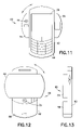
- FIG. 11 is a front view of an alternate embodiment of the present invention.
- FIG. 12 is a rear view of the alternate embodiment shown in FIG. 11 ;
- FIG. 13 is a side view of the alternate embodiment shown in FIG. 11 ;
- FIG. 14 is a front view of another alternate embodiment of the present invention.
- FIG. 15 is a rear view of the alternate embodiment shown in FIG. 14 ;
- FIG. 16 is a side view of the alternate embodiment shown in FIG. 14 ;
- FIG. 17 is a front view as in FIG. 14 with the movable section moved to a landscape position
- FIG. 18 is a rear view of the device shown in FIG. 17 ;
- FIG. 19 is a side view of the device shown in FIG. 17
- FIG. 20 is a schematic illustration showing the device as shown in FIG. 17 being held by a hand of the user for a video call mode
- FIG. 21 is a schematic illustration showing the device as shown in FIG. 17 being held by hands of a user for a camera mode.
- FIG. 1 there is shown a perspective view of a mobile communications device 10 incorporating features of the present invention.
- a mobile communications device 10 incorporating features of the present invention.
- the present invention will be described with reference to the exemplary embodiments shown in the drawings, it should be understood that the present invention can be embodied in many alternate forms of embodiments.
- any suitable size, shape or type of elements or materials could be used.
- the mobile communications device 10 comprises a mobile telephone.
- the telephone 10 is a hand-held flip phone.
- the telephone could comprise any suitable type of telephone including a mono-block type telephone or a communicator bi-fold type telephone.
- the telephone 10 comprises a housing 12 .
- the housing 12 comprises a first portion 14 and a second portion 16 .
- the second portion 16 is pivotably attached to the first portion 14 .
- the second portion 16 can be collapsed over the first portion 14 into a general closed clamshell shape.
- the second portion 16 can be opened relative to the first portion 14 for use of the telephone 10 .
- the telephone 10 when the housing is open, the telephone 10 comprises a front face 20 and a rear face 22 .
- the telephone 10 comprises a transceiver, an antenna, a battery, a keypad 18 and a control input section 24 on the front face 20 .
- the control input section 24 could comprise input keys and/or an input roller and/or joystick or similar device.
- the telephone 10 also comprises a display screen 26 .
- the display screen 26 could comprise a touch screen.
- the display screen 26 is mounted on the second portion 16 and can be viewed at the front face 20 when the second portion 16 is open.
- the display screen 26 has a general rectangular shape and, as seen best in FIG. 4 , is orientated in a general portrait orientation.
- the height of the screen is larger than the width of the screen.
- the display screen 26 could comprise any suitable type of shape.
- the height of the movable section is also larger than the width of the movable section, but any suitable shaped movable section could be provided.
- the telephone 10 comprises a movable section 28 .
- the movable section 28 comprises the display screen 26 .
- the movable section 28 is rotatably mounted to the second portion 16 of the housing 12 .
- the movable section 28 comprises a general lozenge shaped.
- the movable section 28 could comprise any suitable type of shape.
- the movable section 28 is rotatably mounted at the front face 20 .
- the movable section 28 is adapted to rotate relative to the housing 12 90 degrees from the position shown in FIGS. 1 and 4 to the position shown in FIGS. 6 and 7 . In this landscape position shown in FIGS. 6 and 7 , the width of the screen is larger than the height of the screen.
- the width of the movable section is also larger than the height of the movable section.
- FIGS. 1 and 4 show the movable section 28 at a first portrait position. In this first portrait position, the display screen 26 is orientated in its general portrait position shown.
- FIGS. 6 and 7 shows the movable section 28 at a second landscape position. In this second landscape position, the display screen 26 is orientated in a general landscape position shown.
- the terms “portrait” and “landscape” are used to differentiate between two different orientations of the display screen 26 when the display screen has a rectangular shape.
- the display screen could have other shapes and, therefore, besides the classical definitions of the terms “portrait” and “landscape” for a rectangular screen, the terms “portrait” and “landscape” are intended to indicate two different orientations for any given shape of screen.
- the telephone 10 could comprise a user actuatable latch 30 to retain the movable section 28 at either its portrait position or its landscape position.
- the telephone 10 could also comprise one or more springs 32 .
- the spring(s) 32 could be adapted to bias the movable section 28 towards either its portrait position or its landscape position. For example, when the latch 30 is actuated by the user, the movable section 28 could automatically swing or rotate the movable section from its portrait position to its landscape position. Alternatively, or additionally, when the latch 30 is actuated by the user, the movable section 28 could automatically swing or rotate from its landscape position to its portrait position.
- the spring(s) 32 and the latch 30 might not be provided.
- the telephone 10 comprises a first camera 34 (see FIGS. 6 and 7 ) and a second camera 36 (see FIG. 8 ).
- the first camera 34 comprises a video called camera.
- the first camera 34 can send pictures of the user to a person on the other end of the phone call.
- the telephone 10 would normally be held in a speakerphone type of position rather than an headset type of position during this type of video telephone communication.
- the first camera 34 is mounted on the second portion 16 of the housing 12 .
- the first camera 34 comprises a lens 38 which is located at the front face 20 .
- a protective window could be located over the lens.
- the movable section 28 When the movable section 28 is located at its portrait position, a portion 40 of the movable section 28 is located over the lens 38 .
- the movable section 28 covers the lens 38 when the movable section 28 is at its portrait position.
- the lens 38 becomes uncovered as seen in FIGS. 6 and 7 .
- the portion 40 of the movable section 28 is rotated to become a side portion of the movable portion 28 .
- the movable section 28 functions as a cover for the lens 38 of the first camera 34 when the movable section is in its portrait position.
- the side portion 40 which was formerly a bottom portion in the portrait position, extends past a lateral side of the second portion 16 of the housing 12 in the landscape position.
- the second camera 36 preferably comprises a high-resolution still picture digital camera.
- the second camera 36 is mounted on the movable section 28 . More specifically, the second camera 36 is mounted on a portion 42 .
- the portion 42 is a top portion in the portrait position of the movable section 28 and a side portion in the landscape position.
- the camera 36 comprises a lens 44 which is located at a rearward facing side 46 of the movable section 28 .
- a protective cover window could be provided over the lens 44 .
- the rearward facing side 46 of the movable section 28 is substantially completely covered by the second portion 16 of the housing 12 when the movable section 28 is at its portrait position.
- the rearward facing side 46 of the movable section 28 is uncovered at the portions 40 , 42 when the movable section 28 is at its landscape position.
- the lens 44 of the second camera 36 is covered by the second portion 16 of the housing 12 .
- the lens 44 of the second camera 36 is automatically uncovered.
- the lens 44 of the second camera 36 can be automatically covered again by the housing 12 when the movable section 28 is moved back to its portrait position.
- both of the movable section's portions 40 , 42 extend past the lateral sides of the housing's second portion 16 .
- the same portion of the telephone 10 has a general lozenge or elongate shape (or could be a rectangular shape).
- the movable section 28 is preferably mounted to the second portion 16 of the housing 12 to axially rotate about a center axis 78 (see FIG. 6 ) extending through the movable section 28 (and preferably about a center axis extending through the display screen 26 ).
- the rotational axis could be located off center from the center of the movable section 28 , such as at axis 79 shown in FIG. 1 for example.
- the movable section 28 preferably rotates in a planar fashion; along a single plane relative to the second portion 16 .
- the movable section 28 could be adapted to move in multiple axes or planes.
- the movable section 28 is adapted to be rotated only 90 degrees between its first and second positions.
- the movable section 28 could be adapted to rotate 180 degrees.
- the movable section 28 could be adapted to rotate more than 180 degrees if a suitable electrical connector is provided between the movable section 28 and the housing 12 .
- electrical wiring is used to connect the electronic components inside the movable section 28 to the electronic components inside the housing 12 .
- the screen on the phone flips from landscape to portrait (and from portrait to landscape). This could be implemented by the press of a button.
- the mechanism would be sprung to an open position and suitably damped by a dampening system (not shown). In doing so, the screen can reveal a camera, or probably two, one facing towards the user (for video calls) and one away from the user for higher resolution photos.
- the form of the design creates a very aesthetic circle shape when open.
- the present invention solyes the problem of screen orientation and camera lens protection.
- Landscape orientated screens are generally much more suited to picture capture, as in all digital cameras. However finding good ergonomic form factors for this was difficult in the past.
- Portrait screens fit better into a small compact phone and are generally preferred for phone use.
- the conflict between landscape and portrait for different uses is a problem which the present invention overcomes.
- the protection of camera lens from dirt and damage is becoming more critical as the image quality expected from camera phones is increasing. Users require lens covers that are intuitive, cannot accidentally be left open and are simple to use. The present invention addresses this problem.
- the present invention provides a new concept for overcoming various viewing and camera protection issues in an imaging phone. Camera phones and picture viewers are rapidly becoming the norm. Therefore, it is important to protect new and exciting form factors.
- the present invention provided better lens protection. This solution protects and completely hides both camera lenses with one simple mechanical movement. Some designs hide a camera away behind another part of the phone (such as the Nokia Model No. 7650), but the present invention provides the best protection and most intuitive use.
- the present invention allows for both portrait and landscape use of the display screen.
- Portrait and landscape screen use becomes available without necessarily altering the orientation on the user interface (UI).
- the closed position can be used as a neat and compact standard phone, and in the open position (landscape position) as a camera viewfinder and also a picture/movie viewer.
- the present invention provides an intuitive and simple use.
- the simple mechanics mean that it is very intuitive; users would be able to use the product immediately.
- the shape of the design also encourages the user to close the movable section 28 after use. This results in the cameras, inputs, etc., being inclined to be protected.
- the hand-held mobile communications device 50 comprises a mobile telephone having a general mono-block type configuration rather than a flip phone configuration.
- the telephone 50 comprises a housing 52 and a movable section 54 .
- the housing 52 has a general rectangular or lozenge shape.
- the telephone 50 comprises an input section 56 , such as a keypad.
- the movable section 54 is rotatably mounted to the housing 52 at the front face of the housing.
- the movable section comprises a display screen 26 .
- the telephone 50 also comprises a camera 58 .
- the movable section 54 is movable from a portrait position as shown in FIG. 9 and a landscape position as shown in FIG. 10 .
- the hand-held mobile conrunications device 50 has a general lozenge front profile.
- the display screen 26 is orientated in a portrait orientation relative to the housing 52 .
- the display screen 26 is orientated in a landscape orientation relative to the housing 52 .
- a portion of the movable section 54 covers the camera 58 .
- the portion of the movable section which formally covered the camera 58 is moved away from the camera 58 .
- the camera 58 is uncovered.
- a camera could be provided on the rear side of the movable section 54 .
- a camera might not be provided on the front side of the telephone.
- the hand-held mobile communications device 60 comprises a mobile telephone having a general mono-block type configuration rather than a flip phone configuration.
- the telephone 60 comprises a housing 62 and a movable section 64 .
- the housing 62 has a general rectangular or lozenge shape.
- the telephone 60 comprises an input section 66 , such as a keypad.
- the movable section 64 is rotatably mounted to the housing 62 at the rear side 68 of the housing.
- the housing rather than the movable section, comprises the display screen 26 .
- the display screen 26 is mounted to the front side of the housing.
- the telephone 60 also comprises two cameras 70 , 72 .
- the movable section 64 is movable between a portrait position (not shown) and a landscape position as shown in FIGS. 11-13 . In the portrait position the movable section 64 is located substantially entirely behind the housing 62 .
- the display screen 26 is always orientated in a portrait orientation relative to the housing 52 .
- the first camera 70 comprises a video image camera. First camera 70 is mounted in the movable section 64 and has a lens at a forward facing side 74 of the movable section.
- the second camera 72 comprises a high-resolution digital still picture camera. The second camera 72 is mounted in the housing 62 and has a lens at the rear side 68 of the housing.
- the movable section 64 When the movable section 64 is located in its portrait position, a portion of the movable section 64 covers the lens of the second camera 72 . A portion of the housing 62 also covers the lens of the first camera 70 . When the movable section 64 is located in its landscape position, the portion of the movable section which formally covered the second camera 72 is moved away from the second camera 72 . Thus, the second camera 72 is uncovered. Similarly, the portion of the movable section which houses the first camera 70 is moved away from the housing 62 . Thus, the first camera 70 is uncovered.
- the housings comprise pockets or recessed areas which receive the movable sections.
- FIGS. 14-19 an alternate embodiment of a hand-held mobile communications device will be described.
- the device comprises a mobile telephone 80 .
- FIGS. 14-16 show the telephone 80 in a first configuration. In this first configuration the telephone can be used as a telephone or stored by the user.
- the telephone 80 generally comprises a housing 82 and a movable section 84 .
- the housing 82 and the movable section 84 both have a general rectangular or lozenge shape.
- the telephone 80 comprises an input section 86 , such as a keypad and a control input, such as a roller, or joystick, or three-way key, etc.
- the movable section 84 is rotatably mounted to the housing 82 at the rear side 88 (see FIGS. 18-19 ) of the housing.
- the housing rather than the movable section, comprises the display screen 26 .
- the display screen 26 is mounted to the front side of the housing.
- the telephone 80 also comprises two cameras 70 , 72 (see FIGS. 17 and 18 ).
- the telephone 80 is shown in a second configuration.
- the movable section 84 has been rotated 90 degrees relative to the housing 82 .
- the housing 82 and the movable section 84 form general rotating halyes of the telephone 80 .
- the movable section forms the entire rear face of the hand-held mobile communications device when the movable section is in the first portrait position.
- the movable section 84 could comprise the battery for the telephone.
- the movable section 84 also comprises a light or LED flash 90 and a second screen 93 , such as a mini-screen. However, in alternate embodiments any suitable type of flash or video light could be provided, and the second screen might not be provided.
- the device could alternatively or additionally comprise an IR or BLUETOOTH communications device.
- a camera picture taking button 92 is preferably located on the housing 82 as shown in FIG. 21 .
- the second configuration shown in FIGS. 17-19 allows the user to use the telephone in a video call mode, as illustrated by FIG. 20 , or in a camera mode as illustrated by FIG. 21 .
- the housing 82 in addition to housing the second camera 72 , also houses a flash 94 and electrical connectors 96 , 98 .
- two portions 100 , 102 of the movable section 84 extend outward past the lateral sides of the housing 82 . These portions of 100 , 102 form side portions which, as shown in FIG. 21 , former grasping areas for a user's hands 104 to grasping the device 80 while taking pictures. Thus, the user's hands 104 are moved away from the camera 72 and flash 94 .
- the device 80 has a substantially circular shape which can easily fit in the palm of the user's hand 104 such that portions of the user's hand are kept away from the display screen 26 and the camera 70 .
- the invention could be implemented in a number of different phone designs. Mono block phones and flip phones could utilise this design and each has different benefits. As long as the design could be sufficiently protected it could be launched initially as a simple version and then further products released with more features such as hidden cameras, key mats, etc.
Abstract
Description
Claims (5)
Priority Applications (4)
| Application Number | Priority Date | Filing Date | Title |
|---|---|---|---|
| US10/877,525 US7280857B2 (en) | 2004-06-25 | 2004-06-25 | Mobile communications device having rotating display and camera |
| PCT/IB2005/000726 WO2006008588A1 (en) | 2004-06-25 | 2005-03-21 | Improved mobile communication terminal and method |
| CNB2005800251526A CN100566351C (en) | 2004-06-25 | 2005-03-21 | Improved mobile communication terminal and method |
| EP05708778A EP1766941A1 (en) | 2004-06-25 | 2005-03-21 | Improved mobile communication terminal and method |
Applications Claiming Priority (1)
| Application Number | Priority Date | Filing Date | Title |
|---|---|---|---|
| US10/877,525 US7280857B2 (en) | 2004-06-25 | 2004-06-25 | Mobile communications device having rotating display and camera |
Publications (2)
| Publication Number | Publication Date |
|---|---|
| US20050288075A1 US20050288075A1 (en) | 2005-12-29 |
| US7280857B2 true US7280857B2 (en) | 2007-10-09 |
Family
ID=35506644
Family Applications (1)
| Application Number | Title | Priority Date | Filing Date |
|---|---|---|---|
| US10/877,525 Expired - Fee Related US7280857B2 (en) | 2004-06-25 | 2004-06-25 | Mobile communications device having rotating display and camera |
Country Status (4)
| Country | Link |
|---|---|
| US (1) | US7280857B2 (en) |
| EP (1) | EP1766941A1 (en) |
| CN (1) | CN100566351C (en) |
| WO (1) | WO2006008588A1 (en) |
Cited By (14)
| Publication number | Priority date | Publication date | Assignee | Title |
|---|---|---|---|---|
| US20050202856A1 (en) * | 2004-03-12 | 2005-09-15 | Samsung Electronics Co., Ltd. | Swing-type portable terminal |
| US20060023102A1 (en) * | 2004-07-22 | 2006-02-02 | Hiroki Ueno | Imaging device |
| US20060223596A1 (en) * | 2005-03-31 | 2006-10-05 | Pantech Co., Ltd. | Rotating slide-type mobile communication terminal |
| US20060225249A1 (en) * | 2005-04-06 | 2006-10-12 | Samsung Electronics Co., Ltd. | Swing hinge device for mobile terminal |
| US20060274039A1 (en) * | 2005-06-07 | 2006-12-07 | Samsung Electronics Co., Ltd. | Method of performing communication in a wireless terminal and wireless terminal implementing the same |
| US20070171195A1 (en) * | 2006-01-26 | 2007-07-26 | Samsung Electronics Co., Ltd. | Sliding/swing-type portable terminal capable of positioning liquid crystal display at center portion thereof and method of using the same |
| US20080055565A1 (en) * | 2006-09-05 | 2008-03-06 | Solomon Mark C | Projection system and methods |
| US20080074443A1 (en) * | 2006-09-22 | 2008-03-27 | Fujitsu Limited | Electronic device, control method thereof, control program thereof, and recording medium |
| US20080132301A1 (en) * | 2006-11-23 | 2008-06-05 | Samsung Electronics Co., Ltd. | Swing hinge device of a portable terminal and dual hinge device having the same |
| US20080144267A1 (en) * | 2006-12-15 | 2008-06-19 | Fujitsu Limited | Electronic apparatus |
| US20080207272A1 (en) * | 2007-02-28 | 2008-08-28 | Thornton Curtis W | Pivoting mobile terminal |
| CN101621552A (en) * | 2008-07-04 | 2010-01-06 | 深圳富泰宏精密工业有限公司 | Portable electronic device |
| US20100148928A1 (en) * | 2008-12-15 | 2010-06-17 | Mobile Payment Skins Llc | Payment skin with contactless chip |
| US20100267427A1 (en) * | 2006-08-29 | 2010-10-21 | Nokia Corporation | Electronic device with movable housing parts |
Families Citing this family (21)
| Publication number | Priority date | Publication date | Assignee | Title |
|---|---|---|---|---|
| JP3787760B2 (en) * | 2001-07-31 | 2006-06-21 | 松下電器産業株式会社 | Mobile phone device with camera |
| KR100678265B1 (en) * | 2005-01-11 | 2007-02-02 | 삼성전자주식회사 | Semi-automatic swing device for mobile phone |
| TWI274982B (en) * | 2005-05-06 | 2007-03-01 | Asia Optical Co Inc | Handheld input device having a rotating mechanism |
| KR100703332B1 (en) * | 2005-06-07 | 2007-04-03 | 삼성전자주식회사 | Method for changing operation mode in wireless terminal |
| KR100803784B1 (en) * | 2006-11-24 | 2008-02-15 | 삼성전자주식회사 | Sliding/swing module and portable terminal therewith |
| US20080132300A1 (en) * | 2006-11-30 | 2008-06-05 | Motorola, Inc. | Method and apparatus for controlling operation of a portable device by movement of a flip portion of the device |
| US7385150B1 (en) | 2006-12-28 | 2008-06-10 | Microsoft Corporation | Sliding mechanism for device with two keyboards |
| US8749343B2 (en) * | 2007-03-14 | 2014-06-10 | Seth Cirker | Selectively enabled threat based information system |
| US20100019927A1 (en) * | 2007-03-14 | 2010-01-28 | Seth Cirker | Privacy ensuring mobile awareness system |
| US20080254843A1 (en) * | 2007-04-12 | 2008-10-16 | Nokia Corporation | Electronic device having different use positions |
| US8123419B2 (en) | 2007-09-21 | 2012-02-28 | Seth Cirker | Privacy ensuring covert camera |
| US7874744B2 (en) * | 2007-09-21 | 2011-01-25 | Seth Cirker | Privacy ensuring camera enclosure |
| CN101470530B (en) * | 2007-12-26 | 2010-09-29 | 深圳富泰宏精密工业有限公司 | Keyboard device and portable electronic device with the same |
| US20100091178A1 (en) * | 2008-10-14 | 2010-04-15 | Marko Eromaki | Imaging device housing |
| US9286812B2 (en) | 2011-06-07 | 2016-03-15 | Microsoft Technology Licensing, Llc | Flexible display extendable assembly |
| US8711566B2 (en) * | 2011-09-02 | 2014-04-29 | Microsoft Corporation | Expandable mobile device |
| KR20150051773A (en) * | 2013-11-05 | 2015-05-13 | 엘지전자 주식회사 | Mobile terminal |
| US9369170B2 (en) * | 2014-03-04 | 2016-06-14 | Michael Sorrentino | Mobile device case with movable camera cover |
| CN104539804B (en) * | 2014-12-31 | 2017-12-01 | 联想(北京)有限公司 | A kind of electronic equipment and its control method |
| CN208063255U (en) | 2018-02-09 | 2018-11-06 | 广东欧珀移动通信有限公司 | Mobile terminal |
| KR20200091522A (en) | 2019-01-22 | 2020-07-31 | 삼성전자주식회사 | Method for controlling display orientation of content and electronic device thereof |
Citations (13)
| Publication number | Priority date | Publication date | Assignee | Title |
|---|---|---|---|---|
| USD392968S (en) | 1996-02-23 | 1998-03-31 | Nokia Mobile Phones Limited | Communicator |
| USD447740S1 (en) | 2000-09-12 | 2001-09-11 | Nokia Mobile Phones Ltd. | Communicator |
| JP2002135380A (en) * | 2000-10-27 | 2002-05-10 | Matsushita Electric Ind Co Ltd | Fold able mobile electronic device |
| WO2002100076A1 (en) * | 2001-05-31 | 2002-12-12 | Nippon Tojix Co., Ltd. | Cellular telephone |
| WO2003019911A1 (en) * | 2001-07-19 | 2003-03-06 | Zhanxin Zhu | A kind of mobile telephone having rotation display screen |
| US20030203747A1 (en) * | 2002-04-26 | 2003-10-30 | Nec Corporation | Foldable portable telephone having a display portion selectively put into a lengthwise state or an oblong state and a pair of front camera portions |
| US20040185922A1 (en) * | 2003-02-06 | 2004-09-23 | Thomas Sutton | Smartphone with novel opening mechanism |
| USD501838S1 (en) * | 2004-05-05 | 2005-02-15 | Samsung Electronics Co., Ltd. | Portable telephone |
| US20050054393A1 (en) | 2003-09-10 | 2005-03-10 | Nokia Corporation | Movable functional elements for mobile communication device |
| US20050266898A1 (en) * | 2004-05-06 | 2005-12-01 | Samsung Electronics Co., Ltd. | Swing-type portable communication apparatus |
| US7003318B2 (en) * | 2002-09-20 | 2006-02-21 | Hitachi, Ltd. | Mobile phone with camera |
| USD518807S1 (en) * | 2004-06-24 | 2006-04-11 | Samsung Electronics Co., Ltd. | Cellular phone |
| US7050767B2 (en) * | 2003-07-07 | 2006-05-23 | Sony Ericsson Mobile Communications, Ab | Mobile computing devices having rotationally exposed user interface devices |
Family Cites Families (3)
| Publication number | Priority date | Publication date | Assignee | Title |
|---|---|---|---|---|
| GB2375683B (en) * | 2001-05-09 | 2003-07-02 | Motorola Inc | Modular system for a portable communication terminal and module for use therein |
| JP4193411B2 (en) * | 2002-04-26 | 2008-12-10 | 日本電気株式会社 | Mobile phone |
| JP4310084B2 (en) * | 2002-07-30 | 2009-08-05 | 富士通株式会社 | Information processing terminal and guidance display program |
-
2004
- 2004-06-25 US US10/877,525 patent/US7280857B2/en not_active Expired - Fee Related
-
2005
- 2005-03-21 WO PCT/IB2005/000726 patent/WO2006008588A1/en active Application Filing
- 2005-03-21 EP EP05708778A patent/EP1766941A1/en not_active Withdrawn
- 2005-03-21 CN CNB2005800251526A patent/CN100566351C/en not_active Expired - Fee Related
Patent Citations (15)
| Publication number | Priority date | Publication date | Assignee | Title |
|---|---|---|---|---|
| USD392968S (en) | 1996-02-23 | 1998-03-31 | Nokia Mobile Phones Limited | Communicator |
| USD447740S1 (en) | 2000-09-12 | 2001-09-11 | Nokia Mobile Phones Ltd. | Communicator |
| JP2002135380A (en) * | 2000-10-27 | 2002-05-10 | Matsushita Electric Ind Co Ltd | Fold able mobile electronic device |
| US20040127262A1 (en) * | 2001-05-31 | 2004-07-01 | Yoshiharu Ohno | Cellular telephone |
| WO2002100076A1 (en) * | 2001-05-31 | 2002-12-12 | Nippon Tojix Co., Ltd. | Cellular telephone |
| WO2003019911A1 (en) * | 2001-07-19 | 2003-03-06 | Zhanxin Zhu | A kind of mobile telephone having rotation display screen |
| US20040192398A1 (en) * | 2001-07-19 | 2004-09-30 | Zhanxin Zhu | Kind of mobile telephone having rotation display screen |
| US20030203747A1 (en) * | 2002-04-26 | 2003-10-30 | Nec Corporation | Foldable portable telephone having a display portion selectively put into a lengthwise state or an oblong state and a pair of front camera portions |
| US7003318B2 (en) * | 2002-09-20 | 2006-02-21 | Hitachi, Ltd. | Mobile phone with camera |
| US20040185922A1 (en) * | 2003-02-06 | 2004-09-23 | Thomas Sutton | Smartphone with novel opening mechanism |
| US7050767B2 (en) * | 2003-07-07 | 2006-05-23 | Sony Ericsson Mobile Communications, Ab | Mobile computing devices having rotationally exposed user interface devices |
| US20050054393A1 (en) | 2003-09-10 | 2005-03-10 | Nokia Corporation | Movable functional elements for mobile communication device |
| USD501838S1 (en) * | 2004-05-05 | 2005-02-15 | Samsung Electronics Co., Ltd. | Portable telephone |
| US20050266898A1 (en) * | 2004-05-06 | 2005-12-01 | Samsung Electronics Co., Ltd. | Swing-type portable communication apparatus |
| USD518807S1 (en) * | 2004-06-24 | 2006-04-11 | Samsung Electronics Co., Ltd. | Cellular phone |
Non-Patent Citations (3)
| Title |
|---|
| Business World, "Imaging, MMS-capable phone takes center at Nokia's biggest launch to date", Del Castillo, 2001, 4 pages, no month listed. |
| Electronic Translation: JP 2002135380 A. * |
| Press Release, "Nokia's first imaging phone marks start of Multimedia Messaging era", Nokia Corporation, Nov. 19, 2001, 2 pages. |
Cited By (23)
| Publication number | Priority date | Publication date | Assignee | Title |
|---|---|---|---|---|
| US20050202856A1 (en) * | 2004-03-12 | 2005-09-15 | Samsung Electronics Co., Ltd. | Swing-type portable terminal |
| US20060023102A1 (en) * | 2004-07-22 | 2006-02-02 | Hiroki Ueno | Imaging device |
| US7567830B2 (en) * | 2005-03-31 | 2009-07-28 | Pantech Co., Ltd. | Rotating slide-type mobile communication terminal |
| US20060223596A1 (en) * | 2005-03-31 | 2006-10-05 | Pantech Co., Ltd. | Rotating slide-type mobile communication terminal |
| US20060225249A1 (en) * | 2005-04-06 | 2006-10-12 | Samsung Electronics Co., Ltd. | Swing hinge device for mobile terminal |
| US7865151B2 (en) * | 2005-04-06 | 2011-01-04 | Samsung Electronics Co., Ltd | Swing hinge device for mobile terminal |
| US20060274039A1 (en) * | 2005-06-07 | 2006-12-07 | Samsung Electronics Co., Ltd. | Method of performing communication in a wireless terminal and wireless terminal implementing the same |
| US20070171195A1 (en) * | 2006-01-26 | 2007-07-26 | Samsung Electronics Co., Ltd. | Sliding/swing-type portable terminal capable of positioning liquid crystal display at center portion thereof and method of using the same |
| US20100267427A1 (en) * | 2006-08-29 | 2010-10-21 | Nokia Corporation | Electronic device with movable housing parts |
| US20080055565A1 (en) * | 2006-09-05 | 2008-03-06 | Solomon Mark C | Projection system and methods |
| US7670012B2 (en) * | 2006-09-05 | 2010-03-02 | Hewlett-Packard Development Company, L.P. | Projection system and methods |
| US8233072B2 (en) * | 2006-09-22 | 2012-07-31 | Fujitsu Limited | Electronic device, control method thereof, and recording medium |
| US20080074443A1 (en) * | 2006-09-22 | 2008-03-27 | Fujitsu Limited | Electronic device, control method thereof, control program thereof, and recording medium |
| US7991441B2 (en) * | 2006-11-23 | 2011-08-02 | Samsung Electronics Co., Ltd | Swing hinge device of a portable terminal and dual hinge device having the same |
| US20080132301A1 (en) * | 2006-11-23 | 2008-06-05 | Samsung Electronics Co., Ltd. | Swing hinge device of a portable terminal and dual hinge device having the same |
| US20080144267A1 (en) * | 2006-12-15 | 2008-06-19 | Fujitsu Limited | Electronic apparatus |
| US20080207272A1 (en) * | 2007-02-28 | 2008-08-28 | Thornton Curtis W | Pivoting mobile terminal |
| US7970444B2 (en) * | 2007-02-28 | 2011-06-28 | Sony Ericsson Mobile Communications Ab | Pivoting mobile terminal |
| US20100002129A1 (en) * | 2008-07-04 | 2010-01-07 | Shenzhen Futaihong Precision Industry Co., Ltd. | Electronic device having multiple camera modules |
| US8023040B2 (en) * | 2008-07-04 | 2011-09-20 | Shenzhen Futaihong Precision Industry Co., Ltd. | Electronic device having multiple camera modules |
| CN101621552A (en) * | 2008-07-04 | 2010-01-06 | 深圳富泰宏精密工业有限公司 | Portable electronic device |
| CN101621552B (en) * | 2008-07-04 | 2013-10-09 | 深圳富泰宏精密工业有限公司 | Portable electronic device |
| US20100148928A1 (en) * | 2008-12-15 | 2010-06-17 | Mobile Payment Skins Llc | Payment skin with contactless chip |
Also Published As
| Publication number | Publication date |
|---|---|
| WO2006008588A1 (en) | 2006-01-26 |
| CN100566351C (en) | 2009-12-02 |
| EP1766941A1 (en) | 2007-03-28 |
| CN1989760A (en) | 2007-06-27 |
| US20050288075A1 (en) | 2005-12-29 |
Similar Documents
| Publication | Publication Date | Title |
|---|---|---|
| US7280857B2 (en) | Mobile communications device having rotating display and camera | |
| KR100605842B1 (en) | Camera lens module rotating apparatus for mobile phone | |
| EP1860849B1 (en) | Camera protection cover | |
| EP1610530B1 (en) | Dual-axis rotation folder-type portable apparatus | |
| US7092747B2 (en) | Sliding/swing-type portable digital communication apparatus | |
| EP1458169A2 (en) | Bar type portable wireless terminal | |
| US7719611B2 (en) | Handheld electronic device with image-capturing apparatus exposed through window | |
| US20050245295A1 (en) | Handheld mobile terminal | |
| US20060234786A1 (en) | Portable terminal | |
| JP2007282263A (en) | Portable communication device with enhanced image communication capability | |
| EP1538814A1 (en) | Sliding/folding-type portable digital communication apparatus | |
| JP2004215180A (en) | Portable radio terminal | |
| US20050054377A1 (en) | Handheld electronic device having a rotatable image-capturing device | |
| WO2006006023A1 (en) | A mobile terminal concept with a slide and twist mechanism | |
| KR100526555B1 (en) | Portable wireless terminal | |
| US20050245296A1 (en) | Portable dual hinge type communication device usable as personal digital assistant | |
| EP1596597A1 (en) | Handheld electronic device | |
| EP1530344A1 (en) | Handheld electronic device having a rotatable image-capturing device | |
| KR20050036129A (en) | Mobile communication terminal having camera cover for auto-conversion of photograph mode | |
| KR20060083352A (en) | Slide type mobile communication terminal with dual camera | |
| JP4263067B2 (en) | Portable device | |
| JP4327737B2 (en) | Mobile terminal device | |
| JP2005057548A (en) | Mobile terminal device | |
| JP4584442B2 (en) | Digital still camera | |
| JP2005124127A (en) | Mobile unit |
Legal Events
| Date | Code | Title | Description |
|---|---|---|---|
| AS | Assignment |
Owner name: NOKIA CORPORATION, FINLAND Free format text: ASSIGNMENT OF ASSIGNORS INTEREST;ASSIGNOR:GEERNAERT, ADAM;REEL/FRAME:015751/0915 Effective date: 20040702 |
|
| STCF | Information on status: patent grant |
Free format text: PATENTED CASE |
|
| FPAY | Fee payment |
Year of fee payment: 4 |
|
| AS | Assignment |
Owner name: RPX CORPORATION, CALIFORNIA Free format text: ASSIGNMENT OF ASSIGNORS INTEREST;ASSIGNOR:NOKIA CORPORATION;REEL/FRAME:028323/0196 Effective date: 20120531 |
|
| FEPP | Fee payment procedure |
Free format text: PAYOR NUMBER ASSIGNED (ORIGINAL EVENT CODE: ASPN); ENTITY STATUS OF PATENT OWNER: LARGE ENTITY |
|
| FPAY | Fee payment |
Year of fee payment: 8 |
|
| FPAY | Fee payment |
Year of fee payment: 8 |
|
| SULP | Surcharge for late payment |
Year of fee payment: 7 |
|
| AS | Assignment |
Owner name: JEFFERIES FINANCE LLC, NEW YORK Free format text: SECURITY INTEREST;ASSIGNOR:RPX CORPORATION;REEL/FRAME:046486/0433 Effective date: 20180619 |
|
| FEPP | Fee payment procedure |
Free format text: MAINTENANCE FEE REMINDER MAILED (ORIGINAL EVENT CODE: REM.); ENTITY STATUS OF PATENT OWNER: LARGE ENTITY |
|
| LAPS | Lapse for failure to pay maintenance fees |
Free format text: PATENT EXPIRED FOR FAILURE TO PAY MAINTENANCE FEES (ORIGINAL EVENT CODE: EXP.); ENTITY STATUS OF PATENT OWNER: LARGE ENTITY |
|
| STCH | Information on status: patent discontinuation |
Free format text: PATENT EXPIRED DUE TO NONPAYMENT OF MAINTENANCE FEES UNDER 37 CFR 1.362 |
|
| FP | Lapsed due to failure to pay maintenance fee |
Effective date: 20191009 |
|
| AS | Assignment |
Owner name: RPX CORPORATION, CALIFORNIA Free format text: RELEASE BY SECURED PARTY;ASSIGNOR:JEFFERIES FINANCE LLC;REEL/FRAME:054486/0422 Effective date: 20201023 |