US7281840B2 - Chemical mixing apparatus - Google Patents
Chemical mixing apparatus Download PDFInfo
- Publication number
- US7281840B2 US7281840B2 US10/887,705 US88770504A US7281840B2 US 7281840 B2 US7281840 B2 US 7281840B2 US 88770504 A US88770504 A US 88770504A US 7281840 B2 US7281840 B2 US 7281840B2
- Authority
- US
- United States
- Prior art keywords
- ingredient
- chem
- ingredients
- tank
- fractional
- Prior art date
- Legal status (The legal status is an assumption and is not a legal conclusion. Google has not performed a legal analysis and makes no representation as to the accuracy of the status listed.)
- Expired - Fee Related, expires
Links
Images


Classifications
-
- B—PERFORMING OPERATIONS; TRANSPORTING
- B01—PHYSICAL OR CHEMICAL PROCESSES OR APPARATUS IN GENERAL
- B01J—CHEMICAL OR PHYSICAL PROCESSES, e.g. CATALYSIS OR COLLOID CHEMISTRY; THEIR RELEVANT APPARATUS
- B01J4/00—Feed or outlet devices; Feed or outlet control devices
- B01J4/02—Feed or outlet devices; Feed or outlet control devices for feeding measured, i.e. prescribed quantities of reagents
-
- B—PERFORMING OPERATIONS; TRANSPORTING
- B01—PHYSICAL OR CHEMICAL PROCESSES OR APPARATUS IN GENERAL
- B01F—MIXING, e.g. DISSOLVING, EMULSIFYING OR DISPERSING
- B01F23/00—Mixing according to the phases to be mixed, e.g. dispersing or emulsifying
- B01F23/40—Mixing liquids with liquids; Emulsifying
- B01F23/405—Methods of mixing liquids with liquids
-
- B—PERFORMING OPERATIONS; TRANSPORTING
- B01—PHYSICAL OR CHEMICAL PROCESSES OR APPARATUS IN GENERAL
- B01F—MIXING, e.g. DISSOLVING, EMULSIFYING OR DISPERSING
- B01F33/00—Other mixers; Mixing plants; Combinations of mixers
- B01F33/80—Mixing plants; Combinations of mixers
- B01F33/84—Mixing plants with mixing receptacles receiving material dispensed from several component receptacles, e.g. paint tins
-
- B—PERFORMING OPERATIONS; TRANSPORTING
- B01—PHYSICAL OR CHEMICAL PROCESSES OR APPARATUS IN GENERAL
- B01F—MIXING, e.g. DISSOLVING, EMULSIFYING OR DISPERSING
- B01F35/00—Accessories for mixers; Auxiliary operations or auxiliary devices; Parts or details of general application
- B01F35/20—Measuring; Control or regulation
- B01F35/21—Measuring
- B01F35/213—Measuring of the properties of the mixtures, e.g. temperature, density or colour
-
- B—PERFORMING OPERATIONS; TRANSPORTING
- B01—PHYSICAL OR CHEMICAL PROCESSES OR APPARATUS IN GENERAL
- B01F—MIXING, e.g. DISSOLVING, EMULSIFYING OR DISPERSING
- B01F35/00—Accessories for mixers; Auxiliary operations or auxiliary devices; Parts or details of general application
- B01F35/20—Measuring; Control or regulation
- B01F35/21—Measuring
- B01F35/2132—Concentration, pH, pOH, p(ION) or oxygen-demand
-
- B—PERFORMING OPERATIONS; TRANSPORTING
- B01—PHYSICAL OR CHEMICAL PROCESSES OR APPARATUS IN GENERAL
- B01F—MIXING, e.g. DISSOLVING, EMULSIFYING OR DISPERSING
- B01F35/00—Accessories for mixers; Auxiliary operations or auxiliary devices; Parts or details of general application
- B01F35/20—Measuring; Control or regulation
- B01F35/22—Control or regulation
- B01F35/2201—Control or regulation characterised by the type of control technique used
- B01F35/2202—Controlling the mixing process by feed-back, i.e. a measured parameter of the mixture is measured, compared with the set-value and the feed values are corrected
-
- B—PERFORMING OPERATIONS; TRANSPORTING
- B01—PHYSICAL OR CHEMICAL PROCESSES OR APPARATUS IN GENERAL
- B01F—MIXING, e.g. DISSOLVING, EMULSIFYING OR DISPERSING
- B01F35/00—Accessories for mixers; Auxiliary operations or auxiliary devices; Parts or details of general application
- B01F35/20—Measuring; Control or regulation
- B01F35/22—Control or regulation
- B01F35/2201—Control or regulation characterised by the type of control technique used
- B01F35/2209—Controlling the mixing process as a whole, i.e. involving a complete monitoring and controlling of the mixing process during the whole mixing cycle
-
- B—PERFORMING OPERATIONS; TRANSPORTING
- B01—PHYSICAL OR CHEMICAL PROCESSES OR APPARATUS IN GENERAL
- B01F—MIXING, e.g. DISSOLVING, EMULSIFYING OR DISPERSING
- B01F35/00—Accessories for mixers; Auxiliary operations or auxiliary devices; Parts or details of general application
- B01F35/80—Forming a predetermined ratio of the substances to be mixed
- B01F35/82—Forming a predetermined ratio of the substances to be mixed by adding a material to be mixed to a mixture in response to a detected feature, e.g. density, radioactivity, consumed power or colour
-
- B—PERFORMING OPERATIONS; TRANSPORTING
- B01—PHYSICAL OR CHEMICAL PROCESSES OR APPARATUS IN GENERAL
- B01F—MIXING, e.g. DISSOLVING, EMULSIFYING OR DISPERSING
- B01F35/00—Accessories for mixers; Auxiliary operations or auxiliary devices; Parts or details of general application
- B01F35/80—Forming a predetermined ratio of the substances to be mixed
- B01F35/83—Forming a predetermined ratio of the substances to be mixed by controlling the ratio of two or more flows, e.g. using flow sensing or flow controlling devices
- B01F35/832—Flow control by weighing
-
- B—PERFORMING OPERATIONS; TRANSPORTING
- B01—PHYSICAL OR CHEMICAL PROCESSES OR APPARATUS IN GENERAL
- B01F—MIXING, e.g. DISSOLVING, EMULSIFYING OR DISPERSING
- B01F35/00—Accessories for mixers; Auxiliary operations or auxiliary devices; Parts or details of general application
- B01F35/80—Forming a predetermined ratio of the substances to be mixed
- B01F35/88—Forming a predetermined ratio of the substances to be mixed by feeding the materials batchwise
- B01F35/883—Forming a predetermined ratio of the substances to be mixed by feeding the materials batchwise using flow rate controls for feeding the substances
-
- B—PERFORMING OPERATIONS; TRANSPORTING
- B01—PHYSICAL OR CHEMICAL PROCESSES OR APPARATUS IN GENERAL
- B01F—MIXING, e.g. DISSOLVING, EMULSIFYING OR DISPERSING
- B01F35/00—Accessories for mixers; Auxiliary operations or auxiliary devices; Parts or details of general application
- B01F35/90—Heating or cooling systems
-
- G—PHYSICS
- G05—CONTROLLING; REGULATING
- G05D—SYSTEMS FOR CONTROLLING OR REGULATING NON-ELECTRIC VARIABLES
- G05D11/00—Control of flow ratio
- G05D11/02—Controlling ratio of two or more flows of fluid or fluent material
- G05D11/13—Controlling ratio of two or more flows of fluid or fluent material characterised by the use of electric means
- G05D11/131—Controlling ratio of two or more flows of fluid or fluent material characterised by the use of electric means by measuring the values related to the quantity of the individual components
- G05D11/133—Controlling ratio of two or more flows of fluid or fluent material characterised by the use of electric means by measuring the values related to the quantity of the individual components with discontinuous action
- G05D11/134—Controlling ratio of two or more flows of fluid or fluent material characterised by the use of electric means by measuring the values related to the quantity of the individual components with discontinuous action by sensing the weight of the individual components
-
- B—PERFORMING OPERATIONS; TRANSPORTING
- B01—PHYSICAL OR CHEMICAL PROCESSES OR APPARATUS IN GENERAL
- B01J—CHEMICAL OR PHYSICAL PROCESSES, e.g. CATALYSIS OR COLLOID CHEMISTRY; THEIR RELEVANT APPARATUS
- B01J2219/00—Chemical, physical or physico-chemical processes in general; Their relevant apparatus
- B01J2219/00002—Chemical plants
- B01J2219/00027—Process aspects
- B01J2219/00029—Batch processes
-
- B—PERFORMING OPERATIONS; TRANSPORTING
- B01—PHYSICAL OR CHEMICAL PROCESSES OR APPARATUS IN GENERAL
- B01J—CHEMICAL OR PHYSICAL PROCESSES, e.g. CATALYSIS OR COLLOID CHEMISTRY; THEIR RELEVANT APPARATUS
- B01J2219/00—Chemical, physical or physico-chemical processes in general; Their relevant apparatus
- B01J2219/00049—Controlling or regulating processes
- B01J2219/00191—Control algorithm
Definitions
- the present invention relates in general to an apparatus, system and method for mixing chemicals. It more particularly relates to such an apparatus, system and method for mixing ingredients in a precise manner in accordance with a given recipe.
- blended chemical compositions to treat parts during different steps of the process.
- these blended compositions have depended upon the input chemical control devices to achieve the desired mixture, then the mixture is tested in line for acceptable use.
- an external analytical instrument or laboratory is used to confirm the blended mixture.
- an in-line test on the product is used.
- FIG. 1 is a diagrammatic view of a chemical mixing system which is constructed in accordance with an embodiment of the invention
- FIG. 2 is a diagrammatic front elevational view of a tank being filled using a fractional fill method in accordance with the system of FIG. 1 ;
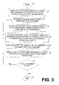
- FIG. 3 is a flow chart of a fractional fill mixing method, which may be utilized with the system of FIG. 1 ;
- FIGS. 4 and 5 are flow charts of another fractional fill mixing method, which may be utilized with the system of FIG. 1 ;
- FIG. 6 is a block diagram of a controller, which is employed with the system of FIG. 1 .
- a system and method of formulating a batch comprising at least two ingredients.
- the ingredients are admitted to a container to partially fill it.
- the quantities of the ingredient in the container are determined, and a ratio of a target quantity to the determined current quantity for at least one ingredient is calculated.
- the next quantity of that ingredient to be admitted to the admixture is calculated by multiplying the target quantity by the calculated ratio to determine a corrected quantity.
- the corrected quantity of the ingredient is admitted to the admixture, and a quantity of another ingredient is admitted to the admixture to adjust the proportion of ingredients to the target formulation.
- the fractional fill apparatus, system and method includes a container for holding ingredients, an in-line analytical instrument for measuring the concentration or quantity of ingredients disposed within the container, and an ingredient supply control device for dispensing ingredients into the container.
- a controller is operatively connected to the ingredient supply control device and the analytical instrument.
- the controller further employs a fractional fill algorithm for admitting at least two ingredients to the container to a fraction of the full volume for a desired batch.
- a controller executes the fractional fill mixing algorithm to cause an initial fraction of the total volume of the container to be filled in the filling sequence. This fractional volume is recirculated to assure a homogeneous mixture, and the in-line analytical instrument determines the constituent parts of the mixture and communicating that information regarding the current mixture to the controller.
- the controller executing a fractional fill mixing algorithm, adjusts the ingredient supply control device in a manner that corrects errors between the actual values and the desired values of the mixture in subsequent fractions or portions of the total volume of the mixture.
- the resulting blend is the desired mixture and no additional testing is required for many applications.
- FIG. 1 there is shown a fractional fill mixing apparatus or system 10 , which is constructed in accordance with an embodiment of the present invention, and which is used to mix two or more ingredients in a tank or container 12 .
- An analyzer or analytical instrument 14 is adapted to measure the quantities of each ingredient in the container 12 .
- An ingredient supply control device shown generally at 16 controllably dispenses two or more ingredients into the tank or container 12 .
- the ingredient supply control device 16 dispenses ingredients through a plurality of ingredient supply inlets, such as first ingredient supply inlet 18 , second ingredient supply inlet 20 , and third ingredient supply inlet 22 .
- Each ingredient supply inlet 18 , 20 , and 22 are connected in fluid communication with a plurality of ingredient supplies (not shown).
- the manifold 24 receives the plurality of ingredients from ingredient supply control device 16 . The ingredients then flow from the manifold 24 to the container 12 .
- the tank or container 12 initially may contain a residual volume of one of the plurality of ingredients to be mixed, as indicated by volLowLev 200 .
- the low level of the tank is, therefore, indicated generally at 210 when a residual volume of one of the ingredients is present in the tank 12 .
- the tank 12 is then fractionally filled seriatim through two or more fractional or partial filling sequences, the volume of each are indicated at 202 , 204 , 206 , and 208 , respectively.
- a fractional filling sequence generally may comprise four fractional filling sequences volFrac 1 , volFrac 2 , volFrac 3 , and volFrac 4 .
- the tank or container 12 may have additional volume capacity above the high level point 212 (not shown).
- the high level point 212 indicates the level that will be achieved when the fractional fill sequence is complete but not necessarily indicate the maximum capacity of the tank 12 .
- the fractional fill mixing method begins in block 27 .
- the fractional fill mixing method admits at least two ingredients to the container 12 to a fraction of the full container 12 volume for a desired batch.
- the method determines the quantities of each ingredient in the container as shown generally in block 30 .
- the quantities of each ingredient measured in the container 12 may be in percent by weight or in percent by volume.
- the method calculates the ratio of the target quantity for the desired mixture to the determined current quantity for at least one of the ingredients as measured in block 30 . This step is generally shown in block 32 .
- the method calculates the next quantity of at least one ingredient by multiplying the target quantity of the ingredient by the ratio calculated in block 32 to determine a corrected quantity.
- the method then directs the ingredient supply control device 16 to admit the corrected quantity of the ingredient to the admixture in the container 12 .
- the method as shown in block 38 , then admits a quantity of another ingredient to adjust the proportion of the ingredients to the target formulation. Steps as shown in blocks 30 , 32 , 34 , 36 , and 38 are repeated until the container is filled to the desired quantity of the batch. When the container 12 is filled to the desired quantity of the batch, the process terminates as shown in block 44 .
- the method includes determining a desired fractional filling sequence of quantities of fractional fills to be performed.
- FIG. 2 shows a tank 12 that will contain the admixture and ultimately the final desired batch to be created from the method.
- FIG. 2 shows a plurality of volume levels for subsequent fractional fill sequences.
- four fractional filling sequences are to be performed.
- the first fractional filling sequence fills the container 12 to approximately 50% of its volume as shown by area 202 and this volume is indicated as volFrac 1 .
- the partial fill volume is equal to 50% in this example including the residual volume as indicated by volLowLev 200 .
- the residual volume is the volume of a residual ingredient already present in the tank 12 before the fractional fill method is commenced. There may or may not be a residual volume, as it depends on the user requirements.
- the residual volume of the ingredient in tank 12 is normally the same ingredient as one of the ingredients that will form part of the current batch.
- the second fractional fill fills the container an additional 25% of volume as indicated by the area 204 where the volume for this fractional fill is represented by volFrac 2 .
- the third and fourth fractional volumes, volFrac 3 and volFrac 4 indicated by 206 and 208 respectively, each fill the container an additional 12.5% until the container is approximately full as indicated by arrow 212 .
- fractional volumes and percentages just recited are for example purposes only and could be modified as desired to achieve various filling sequences as will become apparent to those skilled in the art.
- three fractional filling sequences could be used where each fractional volume sequence could include 33% or one-third of the approximate container volume.
- subsequent discussions of the fractional filling method will utilize four fractional filling sequences.
- the first fractional filling sequence, volFrac 1 will be equal to 50% of the total batch volume
- the second fractional filling sequence, volFrac 2 will contain 25% of the total batch volume
- the third and fourth fractional filling sequences, volFrac 3 and volFrac 4 will each contain 12.5% each of the total batch volume as described previously.
- totalVol which equals (VolLowLev+volFrac 1 +volFrac 2 +volFrac 3 +volFrac 4 ).
- totalVol may also be represented by (chem 1 TotalVol+chem 2 TotalVol+diwAddedVol).
- chem 1 TotalVol represents the total volume of the first ingredient in the batch.
- chem 2 TotalVol represents the total volume of the second ingredient in the batch.
- DiwAddedVol represents the volume of the third ingredient, typically deionized water, added to VolLowLev. It should be noted that diwAddedVol represents the third ingredient and normally is deionized water but may be any other ingredient that is desired to be part of the batch.
- the residual volume of the ingredient in container 12 is defined as being the same ingredient as diwAddedVol, the third ingredient of a desired batch, so that when diwAddedVol and VolLowLev are combined, the total volume of the third ingredient results.
- the fractional fill mixing method then begins by filling the container to the first fractional fill percentage in the sequence. In our example, this is 50% as represented by VolFrac 1 202 , as best shown in FIG. 2 .
- the actual volume of the first ingredient to meet the requirements for the current fractional fill sequence is then calculated. This volume is represented by chem 1 FracVol.
- chem 1 FracVol is equal to chem 1 TotalVol ⁇ pourUp 1 Frac where pourUp 1 Frac is a fractional fill percentage of the first fill sequence, in the present example, 50%.
- chem 2 FracVol is calculated using a similar formula.
- chem 1 TotalVol is defined as chem 1 Ratio ⁇ x where x is an intermediate variable. x is defined as TotalVol ⁇ (chem 1 Ratio+chem 2 Ratio+diwRatio). chem 1 Ratio and chem 2 Ratio are defined as the ratio of the volume to be filled for the first and second ingredients, respectively. diwRatio is a ratio of the volume to be filled for the third ingredients.
- the volume of the third ingredient added to VolLowLev to obtain totalVol is defined as diwAddedVol which equals (diwRatio ⁇ x) ⁇ VolLowLev.
- the fractional fill mixing method next includes calculating the target quantity of one ingredient based on the target volumetric blending ratio and the supply concentration of the ingredient.
- the target quantity of one ingredient is referred to as concChem 1 , which is defined as (chem 1 Ratio ⁇ bulkChem 1 ) ⁇ (chem 1 Ratio+chem 2 Ratio+diwRatio).
- chem 1 Ratio and chem 2 Ratio and diwRatio represent the ratios of the volume to be filled for the first, second, and third ingredient, respectively, for the current fractional fill sequence.
- BulkChem 1 represents the supply concentration of the first ingredient.
- chem 1 FracVol has been calculated
- the first fraction is poured by controller 26 sending a signal to ingredient supply control device 16 to dispense the volume of ingredient represented by chem 1 FracVol then to dispense the volume of ingredient represented by chem 2 FracVol and finally to dispense the volume of chemical as represented by diwFracVol.
- idealChem 1 Frac an ideal chemical fraction
- An ideal chemical fraction may be calculated for each ingredient to be admitted to container 12 .
- idealChem 1 Frac is defined as (chem 1 TotalVol ⁇ pourUp 2 Frac) where chem 1 TotalVol represents the total volume of the first ingredient to meet the requirements for the current fractional fill sequence and pourUp 2 Frac is the subsequent fractional fill percentage in the sequence. For example, since this is the second correction fill sequence, pourUp 2 Frac in this example would now be equal to 25%.
- Other ideal chemical fractions may also be calculated for each ingredient by using a similar formula where chem 1 TotalVol is replaced with the total volume of the other ingredient being evaluated.
- the actual volume of each ingredient to meet the requirements for the current fractional fill sequence must be calculated.
- the actual volume of the first ingredient to meet the requirements for the current fractional fill sequence is represented by chem 1 FracVol which is defined as (idealChem 1 Frac ⁇ concChem 1 ) ⁇ chem 1 Val where chem 1 Val is the measured quantity or concentration of the first ingredient in the batch.
- chem 1 FracVol is defined as (idealChem 1 Frac ⁇ concChem 1 ) ⁇ chem 1 Val
- a similar formula may be used to calculate the actual volumes of the other ingredients to be added to the admixture during this fractal fill sequence where the theoretical quantity/concentration of the other ingredients, ideal chemical fractions, and measured quantities/concentrations may be replaced in the appropriate portions of the above formula.
- the method further includes calculating the difference between the ideal and actual volume of the first ingredient. This is calculated by subtracting chem 1 FracVol from idealChem 1 Frac. The same formula is used for the second ingredient to calculate chem 2 FracDelta using its actual volume to meet the requirements of the current fractional fill sequence and ideal chemical fraction.
- diwFracVol is equal to (diwAddedVol ⁇ pourUp 2 Frac)+chem 1 FracDelta+chem 2 FracDelta where diwAddedVol is the volume of the third ingredient at its VolLowLev to obtain total volume for the third ingredient.
- VolLowLev which represents the residual volume in the container
- chem 1 FracDelta is defined as the difference between the ideal and actual volume of the first ingredient
- chem 2 FracDelta is defined as the difference between the ideal and actual volume of the second ingredient.
- diwFracVol serves to volumetrically fill the remaining volume for the current fractional fill sequence.
- diwAddedVol represents the volume of the third ingredient added to VolLowLev to obtain total volume.
- diwAddedVol is defined as diwRatio ⁇ x ⁇ VolLowLev where x is defined as (TotalVol ⁇ (chem 1 Ratio+chem 2 Ratio+diwRatio)). If it is determined that diwFracVol is negative, diwFracVol is then reduced by multiplying the first ingredient volume to be admitted to the admixture for the current fractional fill sequence by ((totalVol ⁇ VolLowLev) ⁇ pourUp 2 Frac) ⁇ (chem 1 FracVol+chem 2 FracVol). The volume of the second ingredient is also reduced by multiplying it by the same formula.
- the target quantity of one ingredient represented in percent by weight may be modified as a function of specific gravity of each ingredient in the batch.
- concChem 1 by example, may be modified as a function of specific gravity by employing the following replacement formula (chem 1 Ratio bulkChem 1 ⁇ sGravChem 1 ) ⁇ ((chem 1 Ratio ⁇ sGravChem 1 )+(chem 2 Ratio ⁇ sGravChem 2 ))+(diwRatio ⁇ sGravChem 3 )
- concChem 1 is the target concentration of the first ingredient
- chem 1 Ratio is a ratio of the volume to be filled for the first ingredient.
- chem 2 Ratio is a ratio of the volume to be filled for the second ingredient.
- diwRatio is the ratio of the volume to be filled for the third ingredient.
- BulkChem 1 is the supply concentration of the first ingredient.
- sGravChem 1 , sGravChem 2 , sGravChem 3 represent the specific gravity for the first, second, and third ingredients, respectively.
- the above method may be used with concentrated bulk chemicals normally having the concentration measured in percent by weight. Therefore, in the foregoing examples, the formulas listed hereinabove in conjunction with the method for performing fractional fill mixing may use percent by weight concentration as the measure for quantity of the contemplated ingredient in the admixture or from the chemical supply. Alternatively, in other contemplated examples of embodiments of the invention not disclosed herein, percent by volume concentration or other concentration measurement values may be used in some circumstances depending on the type of analytical instrument 14 in use.
- fractional fill sequences are then calculated and added to the admixture in container 12 using the same formulas and methods stated hereinabove for the foregoing examples.
- the fractional fill mixing apparatus, system, and method may be used for chemical blending or mixing concentrated chemicals for use in the manufacture of semiconductor wafers. Therefore, one of the ingredients to be mixed in the admixture may be NH 4 OH, H 2 O 2 , or H 2 O.
- the above mentioned equations may be used to demonstrate how the fractional fill mixing method is employed.
- the first two ingredients are named the (“first ingredient”) and the (“second ingredient”).
- the third ingredient will be deionized water, abbreviated (“diw”).
- each ingredient has a specific gravity equal to one.
- the ingredients be blended together so that a volumetric ratio of 1:1:100 be achieved where the first ingredient forms one part represented by the variable chem 1 Ratio, the second ingredient forms one part represented by the variable chem 2 Ratio and the diw forms 100 parts of the batch represented by the variable diwRatio.
- variable VolLowLev For this example, a 10,000 mL tank 12 will be completely filled with the ingredients.
- the variable totalVol is equal to (chem 1 TotalVol+chem 2 TotalVol+diwAddedVol) where chem 1 TotalVol is the total volume of the first ingredient for the batch.
- chem 2 TotalVol is the total volume of the second ingredient to meet the requirements for the batch and diwAddedVol is the volume of diw to be added to VolLowLev to meet the requirements for the batch.
- chem 1 TotalVol chem 1 Ratio ⁇ (totalVol ⁇ (chem 1 Ratio+chem 2 Ratio+diwRatio)).
- chem 2 TotalVol chem 2 Ratio ⁇ (totalVol ⁇ (chem 1 Ratio+chem 2 Ratio+diwRatio)).
- diwAddedVol which represents the volume of diw to be added to VolLowLev has a slightly different formula to account for the residual volume of diw in the tank 12 .
- the desired number of fractional filling sequence is then determined to be performed and the relative fill percentages to accompany each fill sequence.
- the number of fractional filling sequences and their relative percentages of fill are chosen by the operator. It has been found that this method works well for some applications with four filling sequences where the first sequence fills the container 12 with 50% of the target volume of the completed mixture. This value is assigned to pourUp 1 Frac. The second sequence fills the container 12 with 25% of the target volume of the completed mixture. This is assigned to variable pourUp 2 Frac. The third and fourth sequences fill the container 12 each with 12.5% of the target volume of the completed mixture. These values are assigned to pourUp 3 Frac and pourUp 4 Frac, respectively. Other quantities of filling sequences and their percentages may be chosen by the operator and may be modified to obtain improved results through experimentation.
- the concentrations of the bulk supply for each of the ingredients are determined and will be added to the admixture.
- the bulk supply of the first ingredient has a concentration of 29% by weight and the bulk supply of the second ingredient has a concentration of 30% by weight.
- diw being pure water, in this example, is assumed to be 100% pure.
- the target concentration of the first two ingredients is then calculated.
- the fractional fill method of this example will attempt to formulate the batch to achieve the target concentrations of the first and second ingredients.
- These target concentrations are represented by the variables concChem 1 , concChem 2 where concChem 1 represents the target concentration of the first ingredient and concChem 2 represents the target concentration of the second ingredient.
- the target concentration of diw is not normally calculated as diw is generally used fill the remainder of volume for a fractional fill when the first two ingredients are added to the admixture. Note that concentration may be measured as a quantity or in percent by weight or volume where either may be used in the formulas.
- the next step in the method is to calculate the theoretical volumes of each ingredient to be added to the tank 12 for the first fractional fill sequence
- chem 1 FracVol represents the actual volume of the first ingredient to meet the requirements for the current or first fractional fill sequence.
- Chem 2 FracVol represents the actual volume of the second ingredient to meet the requirements for the current or first fractional fill sequence.
- diwFracVol represents the actual volume of diw to meet the requirements for the current or first fractional fill sequence.
- the ingredients are admitted to the container 12 to a fraction of the full container volume for the first fractional fill sequence.
- the container 12 is then filled with 49 mL of the first ingredient, 49 mL of the second ingredient, and 4902 mL of diw.
- the first fractional fill sequence is now complete.
- the controller 26 may drive the supply control device 16 to dispense the required amount of ingredients using suitable equipment, such as pumps or gravity feed dispensing devices for flow controllers or others.
- suitable equipment such as pumps or gravity feed dispensing devices for flow controllers or others.
- the number of strokes of the pump may be conventionally calculated by the controller 12 and for gravity fed dispensing devices, the dispensing time may be conventionally calculated by the controller 12 .
- the next step in the method 30 requires that the quantities/concentration of each ingredient in the admixture be determined.
- An analytical instrument 14 may be utilized for this purpose.
- the analytical instrument 14 can measure the quantities of each ingredient in the admixture in percent by weight which is why the target quantities/concentration for each ingredient is calculated in percent by weight.
- the measured quantity/concentration of the first ingredient is measured at 0.210% by weight which is assigned to variable chem 1 Val and the measured quantity/concentration of the second ingredient is measured at 0.294% by weight which is assigned to variable chem 2 Val.
- step 32 in the disclosed example of the method the second and all subsequent fractional fill sequences are prepared and, in the present example, the ratio of the target quantity/concentration to the measured quantity/concentration of each ingredient in the admixture is required to be calculated.
- step 34 of this example the next quantity of each of the ingredients is calculated by multiplying the target quantity by the ratio calculated for each respective ingredient in step 32 to determine a corrected quantity. That corrected quantity for each ingredient is then added to the admixture.
- variable idealChem 1 Frac is defined as being equal to chem 1 TotalVol ⁇ pourUp 2 Frac.
- the variable idealChem 2 Frac chem 2 TotalVol ⁇ pourUp 2 Frac.
- chem 1 FracVol is equal to (idealChem 1 Frac ⁇ concChem 1 ) ⁇ chem 1 Val.
- chem 2 FracVol is equal to (idealChem 2 Frac ⁇ concChem 2 ) ⁇ chem 2 Val.
- chem 1 FracVol and chem 2 FracVol are calculated, chem 1 FracDelta and chem 2 FracDelta are then calculated and represent the difference between the ideal and actual volumes of the first and second ingredients, respectively.
- chem 1 FracDelta equals idealChem 1 Frac ⁇ chem 1 FracVol and chem 2 FracDelta equals idealChem 2 Frac ⁇ chem 2 FracVol.
- diwFracVol is equal to (diwAddedVol ⁇ pourUp 2 Frac)+chem 1 FracDelta+chem 2 FracDelta.
- the corrected fractional volumes of each ingredient for the current fractional fill sequence have been calculated, they are admitted into the admixture in accordance with steps 36 and 38 as shown in FIG. 3 .
- 33.1 mL of the first ingredient is added to the admixture
- 24.5 mL of the second ingredient is added to the admixture
- 2442.4 mL of diw is also added to the admixture for the current fractal fill sequence.
- Step 42 as shown in FIG. 3 determines if the container is filled with the desired quantity of the total batch. In the present example, this would occur when all of the fractional fill sequences are completed. If not, then the next fractional fill sequence is begun at step 30 . If all of the fractional fill sequences are completed, the method terminates at step 44 .
- FIGS. 4 and 5 there is shown another embodiment of the present invention which includes a fractional fill method incorporating self diagnostics.
- the method of this embodiment begins at step 46 as best shown in FIG. 4 .
- Stored user-defined parameter values are gathered by the controller 12 for subsequent use within the fractional fill method. These user-defined parameter values may include the number of fractional fill sequences to be performed, and the relative fill volume percentages. The user-defined parameter values may also include information such as concentration information regarding the bulk ingredients to be added to the admixture.
- step 50 calculates the proper volumes of ingredients to be added to the admixture for the first fractional fill sequence. Those ingredients are then added to the admixture. Feedback from an analytical instrument such as the analytical instrument 14 provides the quantity, expressed in a percent by weight, or percent by volume concentration or other, of each of the ingredients in the admixture stored in the tank 12 for the first fractional fill sequence. A decision is then made whether the method is within the first fractional fill sequence or the second fractional fill sequence. If this is true, self-diagnostics are then performed.
- step 58 self-diagnostics begin at step 58 .
- the method of the example evaluates whether or not the first fractional fill sequence was complete. If it was complete, the determination is made whether or not the first fractional sequence delta values are already stored.
- the first fractional fill sequence delta values comprise the difference between the theoretical volumes of the ingredients that should be dispensed into the admixture compared to a revised volume for an ingredient that may be admitted to the admixture due to a variance detected by the analytical instrument 14 .
- controller 26 stores those fractional delta values.
- the method as executed by controller 26 then makes a decision at box 66 as best shown in FIG. 5 and determines whether the second fractional fill sequence is complete. If not, the self-diagnostics method is terminated at step 74 and the method then returns to the method as shown in FIG. 4 at 76 . If the second fractional fill sequence has been completed, step 68 is then performed where the second fractional fill delta values are captured and the differences between the first fractional fill delta values and the second fractional filled delta values are then calculated.
- step 72 is performed which stops the filling sequence and displays an error message.
- step 72 is performed which stops the filling sequence and displays an error message.
- the fractional fill method is unable to correct any deviation in ingredient concentration or quantity between the first fractional fill sequence and the second fractional fill sequence.
- a deviation or delta is discovered in any of the ingredients for the first fractional fill and then a corrective partial fill of ingredients is added in the second fractional fill sequence, assume that it is discovered that the deviation or delta of any of the ingredients did not decrease between the first fractional fill sequence and the second fractional fill sequence. In that case, the fractional fill method is then deemed to be unable to complete the creation of the desired batch.
- the self-diagnostics method terminates at step 74 and returns to the fractional fill method as shown on FIG. 4 at 76 .
- decision box 78 evaluates whether the blended constituents are on target.
- the analytical instrument 14 analyzes the quantity, percent by weight, percent by volume concentration or other, of the chemical constituents depending on the example in the admixture. If they are not on target, an error correction is then calculated for the subsequent fractional fill sequence as described previously. This calculation is performed in step 80 and step 82 . If the blended constituents are on target, then the method immediately transfers to step 82 where the volumes for each ingredient are then calculated for the subsequent fractional fill sequence without having any error correction applied.
- decision box 84 determines if the fourth fraction is complete. It should be understood that if the stored user-defined parameter values in step 48 call for less or more than four fractional fill sequences, decision box 84 , evaluates whether all of the desired fractional fill sequences have been completed.
- step 86 closed loop control of the admixture in tank 12 may begin.
- an air operated process pump 88 may be used to re-circulate the ingredients in the tank 12 to achieve homogeneity of the mixture.
- the pump 88 is operatively connected through a solenoid valve 94 to a source of air under pressure.
- Process pump 88 may be air operated to minimize the risk of any explosions or fires since flammable compounds and ingredients may be flowing through pump 88 .
- Process pump 88 is connected in fluid communication with tank 12 via a conduit 90 .
- a maintenance drain 92 may be in the form of a manual valve for manually performing draining operations from the conduit 90 .
- a filter 96 is disposed in-line with the pump 88 within the recirculation line of the fractal fill mixing apparatus 10 , and a conduit 98 connects the pump 88 to the filter 96 .
- An air operated 3-way valve 102 is connected in the re-circulation line between the pump 88 and the filter 96 via the conduit 98 , to permit the re-ionized water from a source of de-ionized water under pressure to enter the conduit 98 for the purpose of flushing out the fractional fill mixing apparatus 10 .
- a 3-way valve 100 is disposed in line with the valve 102 to permit draining between batches.
- a valve 104 is also connected in line with the valve 102 for permitting nitrogen gas under pressure to enter the fractional fill mixing apparatus 10 .
- a 3-way valve 106 connected in fluid communication down stream of the filter 96 to selectively permit ingredients stored in tank 12 to be delivered via a conduit 124 to a process chamber (not shown) for utilization of the batch.
- a conduit 108 connects the filter 96 in fluid communication with the valve 106 , and an analytical pump 112 .
- a valve 110 may be a solenoid valve which permits air under pressure to drive the analytical pump 112 .
- a conduit 114 is connected in fluid communication between the conduit 108 and the pump 112 to re-circulate the mixture from the tank 12 .
- the analyzer or analytical instrument 14 is connected in fluid communication with the output of the pump 112 via a conduit 116 .
- the analyzer 14 may be a high precision chemical concentration monitor.
- An example of such a device is the SC-1 monitor manufactured by HORIBA and marketed as model no. CS-131.
- the analytical instrument or analyzer 14 is connected in fluid communications with a by-pass re-circulation conduit 120 via a conduit 118 to the valve 106 , so that the mixture is re-circulated through both the analyzer 14 and the by-pass conduit 120 until the delivery valve 106 is actuated to deliver the batch via the conduit 124 , the mixture is re-circulated to the manifold 24 .
- Manifold 24 is connected in fluid communication to the ingredient supply control device generally indicated at 16 via three conduits 132 , 134 and 136 .
- Ingredient supply control device 16 includes three independent ingredient control devices 126 , 128 and 130 . Each control device is capable of accurately dispensing ingredients from a bulk supply (not shown) into the manifold 24 .
- Ingredient control devices 126 , 128 and 130 are each independently fed from the ingredient supply tubes 18 , 20 , and 22 , respectively.
- Manifold 24 is connected in fluid communication with the tank 12 via a conduit 122 .
- the ingredient control devices 126 , 128 , 130 may be any number of control devices such as pumps, gravity feed systems, flow controllers, or other.
- a heater 150 heats the ingredients within the tank 12 .
- a bath temperature controller 170 regulates the heater 150 to control the temperature of the admixture in tank 12 .
- the bath temperature controller 170 measures the temperature of the admixture in the tank 12 via a temperature probe 146 .
- Ingredients supply control device 16 and its individual ingredient control devices 126 , 128 and 130 are controlled by the digital outputs of the controller 26 via a cable 188 .
- the controller 26 may be placed in a communicating relationship to a host computer 168 via a cable 186 , or indirectly via a master controller (not shown) when a distributed network is desired.
- the controller 26 receives a series of recipe parameters from the host computer 168 that describe the desired quantities of each ingredient to be blended together in tank 12 .
- the controller 26 then performs a first fractional fill sequence as previously described.
- the controller 26 sends commands to the ingredient supply control device 16 to dispense the proper amount of ingredients for the first fractional fill.
- the ingredient control devices 126 , 128 and 130 begin accurately dispensing ingredients from their respective bulk ingredient supplies (not shown) via the conduits 18 , 20 and 22 , respectively.
- Each ingredient is then dispensed into the manifold 24 through the conduits 132 , 134 , and 136 .
- the ingredients are partially mixed in manifold 24 and then supplied to the tank 12 through conduit 122 .
- the analyzer 14 is enabled to measure the quantity/concentration of each of the chemical constituents in the admixture stored in tank 12 .
- the pump 88 is activated to re-circulate the mixture from the tank 12 by means of the air valve 94 which causes the admixture stored in tank 12 to flow through the conduits 90 and 98 through the filter 96 and through the conduit 108 .
- the maintenance drain 92 is closed as well as the drain valve 100 , the valve 102 and the valve 104 .
- the valve 106 is also closed.
- the admixture from tank 12 then continues to flow through the by-pass conduit 120 through the manifold 24 and back into the tank 12 .
- the re-circulation flow of the admixture is generally shown by curved arrow 144 .
- the admixture stored in tank 12 is circulated through the various conduits to mix the admixture to create a more homogeneous admixture before the analytical instrument 14 measures its concentration.
- the analytical pump 112 is then enabled through air valve 110 which pumps some of the admixture from the conduit 108 to flow through the conduit 114 through the pump 112 and through the analytical instrument 14 where the concentration of the mixture may be measured.
- the admixture then exits the analytical instrument 14 via the conduit 118 to flow through the manifold 24 and into the tank 12 via the conduit 122 .
- the same general method as just described is performed again.
- the process pump 88 and analytical pump 112 are both disabled through their respective valves 94 and 110 , although for other applications they may not be disabled.
- the bath temperature controller 170 may be enabled to control the heater 150 to heat the admixture to a predetermined temperature. This may be required for some admixtures for subsequent use in a manufacturing process or other process or purpose.
- valve 106 is now open.
- Process pump 88 is then enabled through valve 94 which pumps the admixture from the tank 12 through the conduit 90 , the pump 88 , the conduit 98 , the filter 96 and to the conduit 108 . Because valve 106 is now open, the admixture then flows through valve 106 and through the conduit 124 where it is delivered to the process chamber or other destination.
- a reclaim drain 3-way valve 140 is disposed between conduits, 138 and 142 , so that when reclaimed drain valve 140 is open, a recycled admixture may be reclaimed into the tank 12 through conduits 138 and 142 through valve 140 . It should be noted that in all other operations of the fractional fill mixing system 10 , the reclaim drain valve 140 is normally closed.
- the controller 26 communicates to the bath temperature controller 70 through a serial communications line 160 under the RS-485 protocol. Likewise, the controller 26 may also communicate to the ingredient supply control device 16 and its individual ingredient control devices 126 , 128 and 130 through the digital serial line 188 , or through an analog signal source, if desired. The controller 26 may communicate to the host computer 168 through another serial connection 186 .
- the controller 164 includes a controller package 180 , which includes a plurality of digital inputs, digital outputs, serial ports, A/D channels, and a PLC BUS.
- a controller is a Z-World controller under the model No. PK 2600.
- Such a controller from Z-World contains a BL 1700 controller 183 and an OP 7100 display and touch screen 182 .
- Controller package 180 has a first serial port 182 , which provides RS 232 communications between the controller 180 and an analytical instrument, such as analytical instrument 14 .
- a second serial port 186 provides communications between the controller 180 and the host computer 168 , or to a master controller (not shown).
- a third serial port 158 is also provided on the controller package 180 and provides RS-485 communications to the bath temperature controller 170 as best shown on FIG. 1 .
- Controller package 180 also includes 16 digital outputs shown generally as the cable 188 that are operatively connected to various pumps and valves of the fractional fill mixing apparatus and system 10 , including the ingredient supply control device 16 .
- the controller package 180 also contains 16 digital inputs shown generally as 190 which provide digital input to the controller package 180 for various level sensors, leak detectors and other. Such a level sensor is shown on FIG. 1 as level sensor 154 connected through digital input line 156 to the controller 170 .
- a PLC bus is also included with the controller package 180 and shown generally as 192 .
- the PLC bus emanates from the controller package 180 as a ribbon cable and is attached to a plurality of extension devices, such as an expansion 10 device 194 , auxiliary serial output device 208 , a D/A channel device 199 .
- the PLC bus provides digital input and output control of these accessory devices from the controller package 180 .
- Expansion 10 device 194 provides additional digital outputs which may be used to control additional components in the fractional fill mixing system 10 .
- the auxiliary serial output accessory 208 is also connected to the PLC bus 192 and provides an additional RS 232 communications port used for data logging and chit-chat used primarily for monitoring and software development.
- This RS 232 port shown generally at 210 may be also connected to a recorder 212 for recording and monitoring operations on the controller package 180 .
- Software for the controller package 180 may also be loaded, if desired, through this RS 232 communications port 210 .
- the D/A accessory 199 is additionally connected to the PLC bus 192 and provides analog outputs to control various components on the fractional fill mixing apparatus and system 10 shown generally on FIG. 1 .
- One such component that may be controlled by the D/A accessory 199 may be the ingredient supply control devices 126 , 128 , or 130 as well as the pumps 88 and 114 .
- a TAKVTOI accessory may be operatively coupled to the D/A accessory to convert the analog voltage outputs from the accessory 199 to a plurality of current signals. These current signals created by the TAKVTOI accessory 201 may be used to drive various metering pumps as part of a fractional fill mixing apparatus and system 10 .
- the controller package 180 also includes eight 12-bit A/D channels to monitor a variety of information from the fractional fill mixing system 10 .
- the thermalcouple such as the thermalcouple 146 ( FIG. 1 ) may be coupled to one of the A/D channels 204 so that the controller package 180 may monitor the temperature of the admixture.
- the A/D channels may also monitor various flow controllers or metering pumps which may be part of a typical fractional fill mixing system 10 .
- a fractional fill algorithm or method may be loaded in the form of software to the controller package 180 through a suitable storage media such as a compact disk 206 which contains the fractional fill algorithm or method thereon, or loaded through the RS 232 communications port 210 .
Abstract
Description
| U.S. Pat. No. | Inventor | Issue Date |
| 4,363,742 | Stone, Milton | Dec. 14, 1982 |
| 5,340,210 | Patel, et al. | Aug. 23, 1994 |
| 5,348,389 | Lennart Jönsson, et al. | Sep. 20, 1994 |
| 5,522,660 | O'Dougherty, et al. | Jun. 04, 1996 |
| 5,632,960 | Ferri, J. R., et al. | May 27, 1997 |
| 5,874,049 | Ferri, J. R. et al. | Feb. 23, 1999 |
| 5,924,794 | O'Dougherty, et al. | Jul. 20, 1999 |
| 6,120,175 | Tewell, Stanley | Sep. 19, 2000 |
| 6,290,384 | Pozniak, et al. | Sep. 18, 2001 |
| 2004/0100860 | Wilmer, et al. | May 27, 2004 |
Claims (11)
Priority Applications (8)
| Application Number | Priority Date | Filing Date | Title |
|---|---|---|---|
| US10/887,705 US7281840B2 (en) | 2004-07-09 | 2004-07-09 | Chemical mixing apparatus |
| JP2007520288A JP2008505752A (en) | 2004-07-08 | 2004-12-09 | Chemical mixing apparatus, system and method |
| KR1020077002682A KR20070041556A (en) | 2004-07-08 | 2004-12-09 | Chemical mixing apparatus, system and method |
| EP04813378A EP1766483A4 (en) | 2004-07-08 | 2004-12-09 | Chemical mixing apparatus, system and method |
| US10/593,548 US20080172141A1 (en) | 2004-07-08 | 2004-12-09 | Chemical Mixing Apparatus, System And Method |
| PCT/US2004/041053 WO2006016889A1 (en) | 2004-07-08 | 2004-12-09 | Chemical mixing apparatus, system and method |
| TW094119297A TW200643826A (en) | 2004-07-09 | 2005-06-10 | Handset controlled charging and service provider and operation of the same |
| TW094122988A TW200622539A (en) | 2004-07-09 | 2005-07-07 | Chemical mixing apparatus, system and method |
Applications Claiming Priority (1)
| Application Number | Priority Date | Filing Date | Title |
|---|---|---|---|
| US10/887,705 US7281840B2 (en) | 2004-07-09 | 2004-07-09 | Chemical mixing apparatus |
Publications (2)
| Publication Number | Publication Date |
|---|---|
| US20060009875A1 US20060009875A1 (en) | 2006-01-12 |
| US7281840B2 true US7281840B2 (en) | 2007-10-16 |
Family
ID=35542413
Family Applications (1)
| Application Number | Title | Priority Date | Filing Date |
|---|---|---|---|
| US10/887,705 Expired - Fee Related US7281840B2 (en) | 2004-07-08 | 2004-07-09 | Chemical mixing apparatus |
Country Status (2)
| Country | Link |
|---|---|
| US (1) | US7281840B2 (en) |
| TW (2) | TW200643826A (en) |
Cited By (9)
| Publication number | Priority date | Publication date | Assignee | Title |
|---|---|---|---|---|
| US20070291582A1 (en) * | 2006-06-02 | 2007-12-20 | Schmidt & Heinzmann Gmbh & Co. Kg | Apparatus and method for producing a component mixture from at least two components |
| WO2009064878A1 (en) * | 2007-11-13 | 2009-05-22 | Entegris, Inc. | System and method for blending, monitoring and dispensing chemical mixtures |
| US20090151757A1 (en) * | 2007-12-14 | 2009-06-18 | Mui David S L | Apparatus for particle removal by single-phase and two-phase media |
| US20130148461A1 (en) * | 2010-01-11 | 2013-06-13 | Waters Technologies Corporation | Apparatus And Methods For Controlling The Composition Of Fluids In A Fluid Stream |
| US9770804B2 (en) | 2013-03-18 | 2017-09-26 | Versum Materials Us, Llc | Slurry supply and/or chemical blend supply apparatuses, processes, methods of use and methods of manufacture |
| WO2020239779A1 (en) * | 2019-05-27 | 2020-12-03 | Dieffenbacher GmbH Maschinen- und Anlagenbau | Device and method for producing a binder mix, and system for producing material boards |
| US20210129099A1 (en) * | 2018-07-13 | 2021-05-06 | C&G Hi Tech Co., Ltd. | Device for mixing and supplying liquid |
| WO2023230682A1 (en) * | 2022-05-31 | 2023-12-07 | FARIA, Bruno Pires | Solubilizer for various mixtures |
| US11925912B2 (en) * | 2016-03-11 | 2024-03-12 | Fujifilm Electronic Materials U.S.A., Inc. | Fluid processing systems including a plurality of material tanks, at least one mixing tank, at least one holding tank, and recirculation loops |
Families Citing this family (6)
| Publication number | Priority date | Publication date | Assignee | Title |
|---|---|---|---|---|
| US20060080041A1 (en) | 2004-07-08 | 2006-04-13 | Anderson Gary R | Chemical mixing apparatus, system and method |
| US8424572B2 (en) * | 2009-09-23 | 2013-04-23 | The Procter & Gamble Company | Method for controlling the transfer of materials |
| EP2781256B1 (en) * | 2013-03-18 | 2016-12-07 | Collomix Rühr-und Mischgeräte GmbH | Method for actuating a metering device for the metered delivery of pumpable media, in particular of colouring pigment preparations, metering device, and canister |
| JP2016134569A (en) * | 2015-01-21 | 2016-07-25 | 株式会社東芝 | Semiconductor manufacturing equipment |
| US10429061B2 (en) * | 2016-05-26 | 2019-10-01 | The Babcock & Wilcox Company | Material handling system for fluids |
| CN110539414B (en) * | 2019-09-06 | 2021-10-08 | 杭州永腾橡塑实业有限公司 | Rubber batching system |
Citations (71)
| Publication number | Priority date | Publication date | Assignee | Title |
|---|---|---|---|---|
| US3826904A (en) * | 1970-11-17 | 1974-07-30 | Texaco Inc | Method and apparatus for the optimum blending of lubricating base oils and an additive |
| US3896312A (en) | 1974-06-07 | 1975-07-22 | Christopher W Brown | Petroleum identification |
| US3987808A (en) * | 1974-01-11 | 1976-10-26 | Sandoz Ltd. | Metering system |
| US3997786A (en) | 1975-08-25 | 1976-12-14 | Sun Oil Company Of Pennsylvania | System for spectroscopic analysis of a chemical stream |
| US4251870A (en) | 1980-01-31 | 1981-02-17 | Mobil Oil Corporation | Control of gasoline manufacture |
| US4363742A (en) | 1980-06-17 | 1982-12-14 | Pettibone Corporation | Method and apparatus for making battery paste |
| US4403866A (en) * | 1982-05-07 | 1983-09-13 | E. I. Du Pont De Nemours And Company | Process for making paints |
| US4766551A (en) | 1986-09-22 | 1988-08-23 | Pacific Scientific Company | Method of comparing spectra to identify similar materials |
| US4798954A (en) | 1987-02-03 | 1989-01-17 | Foster-Miller, Inc. | Monitoring technology |
| US4975581A (en) | 1989-06-21 | 1990-12-04 | University Of New Mexico | Method of and apparatus for determining the similarity of a biological analyte from a model constructed from known biological fluids |
| US4994671A (en) | 1987-12-23 | 1991-02-19 | Schlumberger Technology Corporation | Apparatus and method for analyzing the composition of formation fluids |
| US5117370A (en) | 1988-12-22 | 1992-05-26 | Ford Motor Company | Detection system for chemical analysis of zinc phosphate coating solutions |
| US5121338A (en) | 1988-03-10 | 1992-06-09 | Indiana University Foundation | Method for detecting subpopulations in spectral analysis |
| US5124932A (en) | 1988-03-10 | 1992-06-23 | Indiana University Foundation | Method for analyzing asymmetric clusters in spectral analysis |
| US5153140A (en) | 1989-04-28 | 1992-10-06 | Ciba-Geigy Corporation | Process for controlling and optimising industrial processes for the preparation of dyes, fluorescent whitening agents and their intermediates |
| US5225679A (en) | 1992-01-24 | 1993-07-06 | Boston Advanced Technologies, Inc. | Methods and apparatus for determining hydrocarbon fuel properties |
| US5262961A (en) | 1990-12-17 | 1993-11-16 | Farone William A | Method for monitoring and controlling a chemical process |
| US5340210A (en) | 1992-02-25 | 1994-08-23 | Nalco Chemical Company | Apparatus for blending chemicals with a reversible multi-speed pump |
| US5348003A (en) | 1992-09-03 | 1994-09-20 | Sirraya, Inc. | Method and apparatus for chemical analysis |
| US5348389A (en) | 1990-02-19 | 1994-09-20 | Gambro, Ab | System for the preparation of a fluid concentrate intended for medical use |
| US5446681A (en) | 1990-10-12 | 1995-08-29 | Exxon Research And Engineering Company | Method of estimating property and/or composition data of a test sample |
| US5452232A (en) | 1987-08-18 | 1995-09-19 | Bp Oil International Limited | Method and apparatus for determining a property or yield of a hydrocarbon product based on NIRA of the feedstock |
| US5475612A (en) | 1987-08-18 | 1995-12-12 | Bp Oil International Limited | Method for the direct determination of physical properties of hydrocarbon products |
| US5522660A (en) | 1994-12-14 | 1996-06-04 | Fsi International, Inc. | Apparatus for blending and controlling the concentration of a liquid chemical in a diluent liquid |
| US5586066A (en) | 1994-06-08 | 1996-12-17 | Arch Development Corporation | Surveillance of industrial processes with correlated parameters |
| US5592402A (en) | 1992-04-16 | 1997-01-07 | The Dow Chemical Company | Method for interpreting complex data and detecting abnormal instrumentor process behavior |
| US5606164A (en) | 1996-01-16 | 1997-02-25 | Boehringer Mannheim Corporation | Method and apparatus for biological fluid analyte concentration measurement using generalized distance outlier detection |
| US5632960A (en) | 1995-11-07 | 1997-05-27 | Applied Chemical Solutions, Inc. | Two-stage chemical mixing system |
| US5712797A (en) | 1994-10-07 | 1998-01-27 | Bp Chemicals Limited | Property determination |
| US5740073A (en) | 1994-10-07 | 1998-04-14 | Bp Chemicals Limited | Lubricant property determination |
| US5763883A (en) | 1994-10-07 | 1998-06-09 | Bp Chemicals Limited | Chemicals property determination |
| US5924794A (en) | 1995-02-21 | 1999-07-20 | Fsi International, Inc. | Chemical blending system with titrator control |
| US5982486A (en) | 1998-04-23 | 1999-11-09 | Ail Systems, Incorporated | Method and apparatus for on-the-move detection of chemical agents using an FTIR spectrometer |
| US6012019A (en) | 1996-10-23 | 2000-01-04 | Elf Antar France | Process for tracking and monitoring a manufacturing unit and/or a near-infrared spectrometer by means of at least one criterion of quality of sets of spectra |
| US6050283A (en) | 1995-07-07 | 2000-04-18 | Air Liquide America Corporation | System and method for on-site mixing of ultra-high-purity chemicals for semiconductor processing |
| US6070128A (en) | 1995-06-06 | 2000-05-30 | Eutech Engineering Solutions Limited | Method for determining properties using near infra-red (NIR) spectroscopy |
| US6100526A (en) | 1996-12-30 | 2000-08-08 | Dsquared Development, Inc. | Grain quality monitor |
| US6117601A (en) | 1998-12-09 | 2000-09-12 | Fuji Photo Film Co., Ltd. | Method of determining and correcting processing state of photosensitive material based on mahalanobis calculation |
| US6120175A (en) | 1999-07-14 | 2000-09-19 | The Porter Company/Mechanical Contractors | Apparatus and method for controlled chemical blending |
| US6159255A (en) | 1998-12-11 | 2000-12-12 | Sunoco, Inc. (R&M) | Method for predicting intrinsic properties of a mixture |
| US6179954B1 (en) | 1994-02-16 | 2001-01-30 | Fujitsu Limited | Apparatus and method for etching printed circuit board |
| US6290384B1 (en) | 1998-11-24 | 2001-09-18 | The Boc Group, Inc. | Apparatus for producing liquid mixture having predetermined concentration of a specific component |
| US6421614B1 (en) | 1999-07-26 | 2002-07-16 | Donald S. Goldman | Photometer system for obtaining reliable data |
| US6438440B1 (en) | 1998-09-30 | 2002-08-20 | Oki Electric Industry Co., Ltd. | Method and system for managing semiconductor manufacturing equipment |
| US6445969B1 (en) | 1997-01-27 | 2002-09-03 | Circuit Image Systems | Statistical process control integration systems and methods for monitoring manufacturing processes |
| US20020143719A1 (en) | 2000-09-25 | 2002-10-03 | Olympus Optical Co., Ltd. | Pattern classification method and apparatus thereof, and computer readable storage medium |
| US6464799B1 (en) | 1999-06-01 | 2002-10-15 | Applied Materials, Inc. | Method for managing a fluid level associated with a substrate processing tank |
| US20020156549A1 (en) | 2001-04-20 | 2002-10-24 | Shunji Hayashi | Controlling method for manufacturing process |
| US20020155541A1 (en) | 1999-07-16 | 2002-10-24 | Human Genome Sciences, Inc. | Method and system for providing real-time, in situ biomanufacturing process monitoring and control in response to IR spectroscopy |
| US6507401B1 (en) | 1999-12-02 | 2003-01-14 | Aps Technology, Inc. | Apparatus and method for analyzing fluids |
| US20030023390A1 (en) | 2001-04-20 | 2003-01-30 | Fuji Photo Film Co., Ltd. | Composition amount determining method and device for functional mixture |
| US20030050736A1 (en) | 2001-08-31 | 2003-03-13 | Mark Nelson | Diluting system and method |
| US20030095472A1 (en) | 2001-11-19 | 2003-05-22 | Kaijo Corporation | Chemical concentration control device for semiconductor processing apparatus |
| US6604849B2 (en) | 1999-12-03 | 2003-08-12 | Taiwan Semiconductor Manufacturing Co., Ltd. | Slurry dilution system with an ultrasonic vibrator capable of in-situ adjustment of slurry concentration |
| US6630672B1 (en) | 1997-12-23 | 2003-10-07 | Bureau Of Sugar Experiment Stations | On-line measuring system and method |
| US20030199649A1 (en) | 2002-03-26 | 2003-10-23 | Orbison David Robert | Method and apparatus for the controlled dilution of organometallic compounds |
| US20030233198A1 (en) | 2001-11-13 | 2003-12-18 | Genichi Taguchi | Multivariate data analysis method and uses thereof |
| US20040009162A1 (en) | 2002-07-13 | 2004-01-15 | Gerald Pfaff | Process for the production of bulk materials containing small quantities of active substance |
| US20040007180A1 (en) | 2002-07-10 | 2004-01-15 | Tokyo Electron Limited | Film-formation apparatus and source supplying apparatus therefor, gas concentration measuring method |
| US20040034479A1 (en) | 2002-08-07 | 2004-02-19 | Akihiro Shimase | Sample dispensing apparatus and automatic analyzer using the same |
| US6732017B2 (en) * | 2002-02-15 | 2004-05-04 | Lam Research Corp. | System and method for point of use delivery, control and mixing chemical and slurry for CMP/cleaning system |
| US20040100860A1 (en) | 2002-07-19 | 2004-05-27 | Wilmer Jeffrey A. | Method and apparatus for blending process materials |
| US6762832B2 (en) | 2001-07-18 | 2004-07-13 | Air Liquide America, L.P. | Methods and systems for controlling the concentration of a component in a composition with absorption spectroscopy |
| US6766275B2 (en) | 2001-08-31 | 2004-07-20 | Kabushiki Kaisha Toshiba | Method for diagnosing life of manufacturing equipment using rotary machine |
| US6772781B2 (en) | 2000-02-04 | 2004-08-10 | Air Liquide America, L.P. | Apparatus and method for mixing gases |
| US6799883B1 (en) | 1999-12-20 | 2004-10-05 | Air Liquide America L.P. | Method for continuously blending chemical solutions |
| US20040215424A1 (en) | 2001-11-13 | 2004-10-28 | Genichi Taguchi | Multivariate data analysis method and uses thereof |
| US20040228186A1 (en) | 2003-02-25 | 2004-11-18 | Kenichi Kadota | Analysis method for semiconductor device, analysis system and a computer program product |
| US20040236522A1 (en) | 2003-05-22 | 2004-11-25 | Howes Ronald Bruce | Controlling chemical dispense operations based on a conductivity offset |
| US6969190B1 (en) * | 1998-12-23 | 2005-11-29 | Coatings Management Systems, Inc. | Method and apparatus for producing an aqueous paint composition from a plurality of premixed compositions |
| US20060080041A1 (en) | 2004-07-08 | 2006-04-13 | Anderson Gary R | Chemical mixing apparatus, system and method |
Family Cites Families (3)
| Publication number | Priority date | Publication date | Assignee | Title |
|---|---|---|---|---|
| US100860A (en) * | 1870-03-15 | Improvement in railway-car axles | ||
| US50736A (en) * | 1865-10-31 | Milk-stand | ||
| US156549A (en) * | 1874-11-03 | Chaeles b |
-
2004
- 2004-07-09 US US10/887,705 patent/US7281840B2/en not_active Expired - Fee Related
-
2005
- 2005-06-10 TW TW094119297A patent/TW200643826A/en unknown
- 2005-07-07 TW TW094122988A patent/TW200622539A/en unknown
Patent Citations (83)
| Publication number | Priority date | Publication date | Assignee | Title |
|---|---|---|---|---|
| US3826904A (en) * | 1970-11-17 | 1974-07-30 | Texaco Inc | Method and apparatus for the optimum blending of lubricating base oils and an additive |
| US3987808A (en) * | 1974-01-11 | 1976-10-26 | Sandoz Ltd. | Metering system |
| US3896312A (en) | 1974-06-07 | 1975-07-22 | Christopher W Brown | Petroleum identification |
| US3997786A (en) | 1975-08-25 | 1976-12-14 | Sun Oil Company Of Pennsylvania | System for spectroscopic analysis of a chemical stream |
| US4251870A (en) | 1980-01-31 | 1981-02-17 | Mobil Oil Corporation | Control of gasoline manufacture |
| US4363742A (en) | 1980-06-17 | 1982-12-14 | Pettibone Corporation | Method and apparatus for making battery paste |
| US4403866A (en) * | 1982-05-07 | 1983-09-13 | E. I. Du Pont De Nemours And Company | Process for making paints |
| US4766551A (en) | 1986-09-22 | 1988-08-23 | Pacific Scientific Company | Method of comparing spectra to identify similar materials |
| US4798954A (en) | 1987-02-03 | 1989-01-17 | Foster-Miller, Inc. | Monitoring technology |
| US5452232A (en) | 1987-08-18 | 1995-09-19 | Bp Oil International Limited | Method and apparatus for determining a property or yield of a hydrocarbon product based on NIRA of the feedstock |
| US5475612A (en) | 1987-08-18 | 1995-12-12 | Bp Oil International Limited | Method for the direct determination of physical properties of hydrocarbon products |
| US4994671A (en) | 1987-12-23 | 1991-02-19 | Schlumberger Technology Corporation | Apparatus and method for analyzing the composition of formation fluids |
| US5121338A (en) | 1988-03-10 | 1992-06-09 | Indiana University Foundation | Method for detecting subpopulations in spectral analysis |
| US5124932A (en) | 1988-03-10 | 1992-06-23 | Indiana University Foundation | Method for analyzing asymmetric clusters in spectral analysis |
| US5117370A (en) | 1988-12-22 | 1992-05-26 | Ford Motor Company | Detection system for chemical analysis of zinc phosphate coating solutions |
| US5153140A (en) | 1989-04-28 | 1992-10-06 | Ciba-Geigy Corporation | Process for controlling and optimising industrial processes for the preparation of dyes, fluorescent whitening agents and their intermediates |
| US4975581A (en) | 1989-06-21 | 1990-12-04 | University Of New Mexico | Method of and apparatus for determining the similarity of a biological analyte from a model constructed from known biological fluids |
| US5348389A (en) | 1990-02-19 | 1994-09-20 | Gambro, Ab | System for the preparation of a fluid concentrate intended for medical use |
| US5446681A (en) | 1990-10-12 | 1995-08-29 | Exxon Research And Engineering Company | Method of estimating property and/or composition data of a test sample |
| US5262961A (en) | 1990-12-17 | 1993-11-16 | Farone William A | Method for monitoring and controlling a chemical process |
| US5225679A (en) | 1992-01-24 | 1993-07-06 | Boston Advanced Technologies, Inc. | Methods and apparatus for determining hydrocarbon fuel properties |
| US5340210A (en) | 1992-02-25 | 1994-08-23 | Nalco Chemical Company | Apparatus for blending chemicals with a reversible multi-speed pump |
| US5592402A (en) | 1992-04-16 | 1997-01-07 | The Dow Chemical Company | Method for interpreting complex data and detecting abnormal instrumentor process behavior |
| US5348003A (en) | 1992-09-03 | 1994-09-20 | Sirraya, Inc. | Method and apparatus for chemical analysis |
| US6179954B1 (en) | 1994-02-16 | 2001-01-30 | Fujitsu Limited | Apparatus and method for etching printed circuit board |
| US5586066A (en) | 1994-06-08 | 1996-12-17 | Arch Development Corporation | Surveillance of industrial processes with correlated parameters |
| US5740073A (en) | 1994-10-07 | 1998-04-14 | Bp Chemicals Limited | Lubricant property determination |
| US5763883A (en) | 1994-10-07 | 1998-06-09 | Bp Chemicals Limited | Chemicals property determination |
| US5712797A (en) | 1994-10-07 | 1998-01-27 | Bp Chemicals Limited | Property determination |
| US5522660A (en) | 1994-12-14 | 1996-06-04 | Fsi International, Inc. | Apparatus for blending and controlling the concentration of a liquid chemical in a diluent liquid |
| US5924794A (en) | 1995-02-21 | 1999-07-20 | Fsi International, Inc. | Chemical blending system with titrator control |
| US6070128A (en) | 1995-06-06 | 2000-05-30 | Eutech Engineering Solutions Limited | Method for determining properties using near infra-red (NIR) spectroscopy |
| US6050283A (en) | 1995-07-07 | 2000-04-18 | Air Liquide America Corporation | System and method for on-site mixing of ultra-high-purity chemicals for semiconductor processing |
| US5874049A (en) | 1995-11-07 | 1999-02-23 | Applied Chemical Solutions, Inc. | Two-stage chemical mixing system |
| US5632960A (en) | 1995-11-07 | 1997-05-27 | Applied Chemical Solutions, Inc. | Two-stage chemical mixing system |
| US5606164A (en) | 1996-01-16 | 1997-02-25 | Boehringer Mannheim Corporation | Method and apparatus for biological fluid analyte concentration measurement using generalized distance outlier detection |
| US6012019A (en) | 1996-10-23 | 2000-01-04 | Elf Antar France | Process for tracking and monitoring a manufacturing unit and/or a near-infrared spectrometer by means of at least one criterion of quality of sets of spectra |
| US6100526A (en) | 1996-12-30 | 2000-08-08 | Dsquared Development, Inc. | Grain quality monitor |
| US6445969B1 (en) | 1997-01-27 | 2002-09-03 | Circuit Image Systems | Statistical process control integration systems and methods for monitoring manufacturing processes |
| US6630672B1 (en) | 1997-12-23 | 2003-10-07 | Bureau Of Sugar Experiment Stations | On-line measuring system and method |
| US5982486A (en) | 1998-04-23 | 1999-11-09 | Ail Systems, Incorporated | Method and apparatus for on-the-move detection of chemical agents using an FTIR spectrometer |
| US20040098161A1 (en) | 1998-09-30 | 2004-05-20 | Shunji Hayashi | Method and systme for managing semiconductor manufacturing equipment |
| US20020188367A1 (en) | 1998-09-30 | 2002-12-12 | Shunji Hayashi | Method and system for managing semiconductor manufacturing equipment |
| US6665576B2 (en) | 1998-09-30 | 2003-12-16 | Oki Electric Industry Co., Ltd. | Method and system for managing semiconductor manufacturing equipment |
| US6438440B1 (en) | 1998-09-30 | 2002-08-20 | Oki Electric Industry Co., Ltd. | Method and system for managing semiconductor manufacturing equipment |
| US6290384B1 (en) | 1998-11-24 | 2001-09-18 | The Boc Group, Inc. | Apparatus for producing liquid mixture having predetermined concentration of a specific component |
| US6117601A (en) | 1998-12-09 | 2000-09-12 | Fuji Photo Film Co., Ltd. | Method of determining and correcting processing state of photosensitive material based on mahalanobis calculation |
| US6159255A (en) | 1998-12-11 | 2000-12-12 | Sunoco, Inc. (R&M) | Method for predicting intrinsic properties of a mixture |
| US6969190B1 (en) * | 1998-12-23 | 2005-11-29 | Coatings Management Systems, Inc. | Method and apparatus for producing an aqueous paint composition from a plurality of premixed compositions |
| US6464799B1 (en) | 1999-06-01 | 2002-10-15 | Applied Materials, Inc. | Method for managing a fluid level associated with a substrate processing tank |
| US6120175A (en) | 1999-07-14 | 2000-09-19 | The Porter Company/Mechanical Contractors | Apparatus and method for controlled chemical blending |
| US20020155541A1 (en) | 1999-07-16 | 2002-10-24 | Human Genome Sciences, Inc. | Method and system for providing real-time, in situ biomanufacturing process monitoring and control in response to IR spectroscopy |
| US6421614B1 (en) | 1999-07-26 | 2002-07-16 | Donald S. Goldman | Photometer system for obtaining reliable data |
| US6507401B1 (en) | 1999-12-02 | 2003-01-14 | Aps Technology, Inc. | Apparatus and method for analyzing fluids |
| US6707556B2 (en) | 1999-12-02 | 2004-03-16 | Aps Technology, Inc. | Apparatus and method for analyzing fluids |
| US6604849B2 (en) | 1999-12-03 | 2003-08-12 | Taiwan Semiconductor Manufacturing Co., Ltd. | Slurry dilution system with an ultrasonic vibrator capable of in-situ adjustment of slurry concentration |
| US6799883B1 (en) | 1999-12-20 | 2004-10-05 | Air Liquide America L.P. | Method for continuously blending chemical solutions |
| US6772781B2 (en) | 2000-02-04 | 2004-08-10 | Air Liquide America, L.P. | Apparatus and method for mixing gases |
| US20020143719A1 (en) | 2000-09-25 | 2002-10-03 | Olympus Optical Co., Ltd. | Pattern classification method and apparatus thereof, and computer readable storage medium |
| US20020156549A1 (en) | 2001-04-20 | 2002-10-24 | Shunji Hayashi | Controlling method for manufacturing process |
| US20030023390A1 (en) | 2001-04-20 | 2003-01-30 | Fuji Photo Film Co., Ltd. | Composition amount determining method and device for functional mixture |
| US6862484B2 (en) | 2001-04-20 | 2005-03-01 | Oki Electric Industry Co., Ltd. | Controlling method for manufacturing process |
| US6681187B2 (en) | 2001-04-20 | 2004-01-20 | Fuji Photo Film Co., Ltd. | Composition amount determining method and device for functional mixture |
| US6762832B2 (en) | 2001-07-18 | 2004-07-13 | Air Liquide America, L.P. | Methods and systems for controlling the concentration of a component in a composition with absorption spectroscopy |
| US20030050736A1 (en) | 2001-08-31 | 2003-03-13 | Mark Nelson | Diluting system and method |
| US6766275B2 (en) | 2001-08-31 | 2004-07-20 | Kabushiki Kaisha Toshiba | Method for diagnosing life of manufacturing equipment using rotary machine |
| US20040215424A1 (en) | 2001-11-13 | 2004-10-28 | Genichi Taguchi | Multivariate data analysis method and uses thereof |
| US20030233198A1 (en) | 2001-11-13 | 2003-12-18 | Genichi Taguchi | Multivariate data analysis method and uses thereof |
| US20030095472A1 (en) | 2001-11-19 | 2003-05-22 | Kaijo Corporation | Chemical concentration control device for semiconductor processing apparatus |
| US6732017B2 (en) * | 2002-02-15 | 2004-05-04 | Lam Research Corp. | System and method for point of use delivery, control and mixing chemical and slurry for CMP/cleaning system |
| US20040199293A1 (en) | 2002-02-15 | 2004-10-07 | Lam Research Corporation | System and method for point of use delivery, control and mixing chemical and slurry for CMP/cleaning system |
| US20030199649A1 (en) | 2002-03-26 | 2003-10-23 | Orbison David Robert | Method and apparatus for the controlled dilution of organometallic compounds |
| US20040007180A1 (en) | 2002-07-10 | 2004-01-15 | Tokyo Electron Limited | Film-formation apparatus and source supplying apparatus therefor, gas concentration measuring method |
| US20040009162A1 (en) | 2002-07-13 | 2004-01-15 | Gerald Pfaff | Process for the production of bulk materials containing small quantities of active substance |
| US20040100860A1 (en) | 2002-07-19 | 2004-05-27 | Wilmer Jeffrey A. | Method and apparatus for blending process materials |
| US20040034479A1 (en) | 2002-08-07 | 2004-02-19 | Akihiro Shimase | Sample dispensing apparatus and automatic analyzer using the same |
| US20040228186A1 (en) | 2003-02-25 | 2004-11-18 | Kenichi Kadota | Analysis method for semiconductor device, analysis system and a computer program product |
| US20040236522A1 (en) | 2003-05-22 | 2004-11-25 | Howes Ronald Bruce | Controlling chemical dispense operations based on a conductivity offset |
| US20060080041A1 (en) | 2004-07-08 | 2006-04-13 | Anderson Gary R | Chemical mixing apparatus, system and method |
| US20070043471A1 (en) | 2005-07-08 | 2007-02-22 | Anderson Gary R | Batch mixing method with standard deviation homogeneity monitoring |
| US20070043473A1 (en) | 2005-07-08 | 2007-02-22 | Anderson Gary R | Point-of-use mixing method with standard deviation homogeneity monitoring |
| US20070043472A1 (en) | 2005-07-08 | 2007-02-22 | Anderson Gary R | Batch mixing method with first derivative homogeneity monitoring |
| US20070106425A1 (en) | 2005-07-08 | 2007-05-10 | Anderson Gary R | Point-of-use mixing method with first derivative homogeneity monitoring |
Non-Patent Citations (8)
| Title |
|---|
| Co-Pending U.S. Appl. No. 10/593,548 entitled "Chemical Mixing Apparaatus System and Method" to Simpson et al. filed Sep. 19, 2006; Available in PAIR. |
| PCT Search Report and Written Opinion for International Application No. PCT/US2006/026687 mailed Jan. 4, 2007; 10 pages. |
| PCT Search Report for International Application No. PCT/US04/41053 mailed May 23, 2005, 1 page. |
| U. S. Patent and Trademark Office, "Communication", for U.S. Appl. No. 11/484,019, mailed May 14, 2007; available in PAIR. |
| U. S. Patent and Trademark Office, "Communication", for U.S. Appl. No. 11/484,020, mailed May 14, 2007; available in PAIR. |
| U. S. Patent and Trademark Office, "Communication", for U.S. Appl. No. 11/484,021, mailed May 14, 2007; available in PAIR. |
| U.S. Appl. No. 11/177,930 to Anderson et al. entitled "Chemical Mixing Apparatus, System and Method." |
| U.S. Patent and Trademark Office, "Communication", U.S. Appl. No. 11/484,014, mailed May 14, 2007; available in PAIR. |
Cited By (12)
| Publication number | Priority date | Publication date | Assignee | Title |
|---|---|---|---|---|
| US20070291582A1 (en) * | 2006-06-02 | 2007-12-20 | Schmidt & Heinzmann Gmbh & Co. Kg | Apparatus and method for producing a component mixture from at least two components |
| WO2009064878A1 (en) * | 2007-11-13 | 2009-05-22 | Entegris, Inc. | System and method for blending, monitoring and dispensing chemical mixtures |
| US20090151757A1 (en) * | 2007-12-14 | 2009-06-18 | Mui David S L | Apparatus for particle removal by single-phase and two-phase media |
| US8084406B2 (en) * | 2007-12-14 | 2011-12-27 | Lam Research Corporation | Apparatus for particle removal by single-phase and two-phase media |
| US8758522B2 (en) | 2007-12-14 | 2014-06-24 | Lam Research Corporation | Method and apparatus for removing contaminants from substrate |
| US20130148461A1 (en) * | 2010-01-11 | 2013-06-13 | Waters Technologies Corporation | Apparatus And Methods For Controlling The Composition Of Fluids In A Fluid Stream |
| US9770804B2 (en) | 2013-03-18 | 2017-09-26 | Versum Materials Us, Llc | Slurry supply and/or chemical blend supply apparatuses, processes, methods of use and methods of manufacture |
| US10562151B2 (en) | 2013-03-18 | 2020-02-18 | Versum Materials Us, Llc | Slurry supply and/or chemical blend supply apparatuses, processes, methods of use and methods of manufacture |
| US11925912B2 (en) * | 2016-03-11 | 2024-03-12 | Fujifilm Electronic Materials U.S.A., Inc. | Fluid processing systems including a plurality of material tanks, at least one mixing tank, at least one holding tank, and recirculation loops |
| US20210129099A1 (en) * | 2018-07-13 | 2021-05-06 | C&G Hi Tech Co., Ltd. | Device for mixing and supplying liquid |
| WO2020239779A1 (en) * | 2019-05-27 | 2020-12-03 | Dieffenbacher GmbH Maschinen- und Anlagenbau | Device and method for producing a binder mix, and system for producing material boards |
| WO2023230682A1 (en) * | 2022-05-31 | 2023-12-07 | FARIA, Bruno Pires | Solubilizer for various mixtures |
Also Published As
| Publication number | Publication date |
|---|---|
| TW200643826A (en) | 2006-12-16 |
| TW200622539A (en) | 2006-07-01 |
| US20060009875A1 (en) | 2006-01-12 |
Similar Documents
| Publication | Publication Date | Title |
|---|---|---|
| US20060080041A1 (en) | Chemical mixing apparatus, system and method | |
| US7281840B2 (en) | Chemical mixing apparatus | |
| US6767877B2 (en) | Method and system for chemical injection in silicon wafer processing | |
| KR100394181B1 (en) | Two-stage chemical mixing system | |
| US7054719B2 (en) | System and method for point of use delivery, control and mixing chemical and slurry for CMP/cleaning system | |
| US9666435B2 (en) | Apparatus and process for integrated gas blending | |
| JP5961112B2 (en) | Method and system for preparing a liquid mixture | |
| JP3882148B2 (en) | Continuous automatic manufacturing system for automobiles and other paints | |
| US6880727B2 (en) | Precision liquid mixing apparatus and method | |
| CN110622092B (en) | Method and mixing device for preparing flowable coatings on a batch basis | |
| CN105036284A (en) | Devices, systems, and methods for carbonation of deionized water | |
| CA1290744C (en) | Process and an apparatus for mixing substances | |
| US20080172141A1 (en) | Chemical Mixing Apparatus, System And Method | |
| KR102394219B1 (en) | Point-of-use mixing systems and methods for controlling temperatures of liquids dispensed at substrate | |
| TW202138128A (en) | On-demand in-line-blending and supply of chemicals | |
| JPH0629207A (en) | Preparation method of developing solution | |
| JP2023184504A (en) | Dynamic method for rapidly filling identical batches of bottle of gas mixtures with high metrological precision | |
| CN1997949A (en) | Chemical mixing apparatus, system and method | |
| JPS6230919A (en) | Automatic apparatus for injection and weighing | |
| JP2000218143A (en) | Chemical solution mixing equipment and supply quantity control method | |
| JPH0869318A (en) | Plant operation aid equipment |
Legal Events
| Date | Code | Title | Description |
|---|---|---|---|
| AS | Assignment |
Owner name: TRES-ARK, INC., TEXAS Free format text: ASSIGNMENT OF ASSIGNORS INTEREST;ASSIGNORS:SIMPSON, MICHAEL B.;WOODLEY, GEORGE V.;ANDERSON, GARY R.;REEL/FRAME:015103/0454;SIGNING DATES FROM 20040730 TO 20040824 |
|
| FEPP | Fee payment procedure |
Free format text: PAYOR NUMBER ASSIGNED (ORIGINAL EVENT CODE: ASPN); ENTITY STATUS OF PATENT OWNER: SMALL ENTITY |
|
| AS | Assignment |
Owner name: LOWE, JOHN PATRICK, TRUSTEE, CHAPTER 7 CASE NO. 09 Free format text: ASSIGNMENT OF ASSIGNORS INTEREST;ASSIGNOR:TRES-ARK, INC.;REEL/FRAME:023607/0650 Effective date: 20091106 |
|
| AS | Assignment |
Owner name: REVELS, JASON P, MINNESOTA Free format text: ASSIGNMENT OF ASSIGNORS INTEREST;ASSIGNOR:LOWE, JOHN PATRICK;REEL/FRAME:025367/0990 Effective date: 20101105 |
|
| REMI | Maintenance fee reminder mailed | ||
| LAPS | Lapse for failure to pay maintenance fees | ||
| REIN | Reinstatement after maintenance fee payment confirmed | ||
| FP | Lapsed due to failure to pay maintenance fee |
Effective date: 20111016 |
|
| FEPP | Fee payment procedure |
Free format text: PETITION RELATED TO MAINTENANCE FEES GRANTED (ORIGINAL EVENT CODE: PMFG); ENTITY STATUS OF PATENT OWNER: SMALL ENTITY |
|
| FPAY | Fee payment |
Year of fee payment: 4 |
|
| PRDP | Patent reinstated due to the acceptance of a late maintenance fee |
Effective date: 20131016 |
|
| STCF | Information on status: patent grant |
Free format text: PATENTED CASE |
|
| REMI | Maintenance fee reminder mailed | ||
| FPAY | Fee payment |
Year of fee payment: 8 |
|
| SULP | Surcharge for late payment |
Year of fee payment: 7 |
|
| AS | Assignment |
Owner name: TRESARK, TEXAS Free format text: ASSIGNMENT OF ASSIGNORS INTEREST;ASSIGNOR:REVELS, JASON;REEL/FRAME:039504/0417 Effective date: 20160428 |
|
| FEPP | Fee payment procedure |
Free format text: MAINTENANCE FEE REMINDER MAILED (ORIGINAL EVENT CODE: REM.); ENTITY STATUS OF PATENT OWNER: SMALL ENTITY |
|
| LAPS | Lapse for failure to pay maintenance fees |
Free format text: PATENT EXPIRED FOR FAILURE TO PAY MAINTENANCE FEES (ORIGINAL EVENT CODE: EXP.); ENTITY STATUS OF PATENT OWNER: SMALL ENTITY |
|
| STCH | Information on status: patent discontinuation |
Free format text: PATENT EXPIRED DUE TO NONPAYMENT OF MAINTENANCE FEES UNDER 37 CFR 1.362 |
|
| FP | Lapsed due to failure to pay maintenance fee |
Effective date: 20191016 |