US7283187B2 - Method of fabricating hologram diffuser for liquid crystal display and liquid crystal display device using the same - Google Patents
Method of fabricating hologram diffuser for liquid crystal display and liquid crystal display device using the same Download PDFInfo
- Publication number
- US7283187B2 US7283187B2 US11/179,484 US17948405A US7283187B2 US 7283187 B2 US7283187 B2 US 7283187B2 US 17948405 A US17948405 A US 17948405A US 7283187 B2 US7283187 B2 US 7283187B2
- Authority
- US
- United States
- Prior art keywords
- liquid crystal
- layer
- hologram layer
- crystal display
- hologram
- Prior art date
- Legal status (The legal status is an assumption and is not a legal conclusion. Google has not performed a legal analysis and makes no representation as to the accuracy of the status listed.)
- Expired - Lifetime
Links
- 239000004973 liquid crystal related substance Substances 0.000 title claims abstract description 79
- 238000004519 manufacturing process Methods 0.000 title description 7
- 239000000758 substrate Substances 0.000 claims abstract description 46
- 238000009499 grossing Methods 0.000 claims abstract description 40
- 239000011347 resin Substances 0.000 claims abstract description 25
- 229920005989 resin Polymers 0.000 claims abstract description 25
- 230000000007 visual effect Effects 0.000 claims abstract description 18
- 239000010408 film Substances 0.000 claims description 39
- 238000009792 diffusion process Methods 0.000 claims description 11
- 239000011159 matrix material Substances 0.000 claims description 6
- 239000010409 thin film Substances 0.000 claims description 2
- 230000000295 complement effect Effects 0.000 claims 8
- 239000004988 Nematic liquid crystal Substances 0.000 claims 1
- 230000010287 polarization Effects 0.000 description 10
- 238000000034 method Methods 0.000 description 6
- 239000000463 material Substances 0.000 description 4
- 238000003825 pressing Methods 0.000 description 4
- 238000004528 spin coating Methods 0.000 description 3
- 239000004986 Cholesteric liquid crystals (ChLC) Substances 0.000 description 2
- 230000015572 biosynthetic process Effects 0.000 description 2
- 230000004048 modification Effects 0.000 description 2
- 238000012986 modification Methods 0.000 description 2
- 239000011248 coating agent Substances 0.000 description 1
- 238000000576 coating method Methods 0.000 description 1
- 238000007796 conventional method Methods 0.000 description 1
- 230000000694 effects Effects 0.000 description 1
- 238000007765 extrusion coating Methods 0.000 description 1
- 238000002156 mixing Methods 0.000 description 1
- 230000005855 radiation Effects 0.000 description 1
- 238000010345 tape casting Methods 0.000 description 1
Images


Classifications
-
- G—PHYSICS
- G02—OPTICS
- G02F—OPTICAL DEVICES OR ARRANGEMENTS FOR THE CONTROL OF LIGHT BY MODIFICATION OF THE OPTICAL PROPERTIES OF THE MEDIA OF THE ELEMENTS INVOLVED THEREIN; NON-LINEAR OPTICS; FREQUENCY-CHANGING OF LIGHT; OPTICAL LOGIC ELEMENTS; OPTICAL ANALOGUE/DIGITAL CONVERTERS
- G02F1/00—Devices or arrangements for the control of the intensity, colour, phase, polarisation or direction of light arriving from an independent light source, e.g. switching, gating or modulating; Non-linear optics
- G02F1/01—Devices or arrangements for the control of the intensity, colour, phase, polarisation or direction of light arriving from an independent light source, e.g. switching, gating or modulating; Non-linear optics for the control of the intensity, phase, polarisation or colour
- G02F1/13—Devices or arrangements for the control of the intensity, colour, phase, polarisation or direction of light arriving from an independent light source, e.g. switching, gating or modulating; Non-linear optics for the control of the intensity, phase, polarisation or colour based on liquid crystals, e.g. single liquid crystal display cells
- G02F1/133—Constructional arrangements; Operation of liquid crystal cells; Circuit arrangements
- G02F1/1333—Constructional arrangements; Manufacturing methods
- G02F1/1335—Structural association of cells with optical devices, e.g. polarisers or reflectors
-
- G—PHYSICS
- G02—OPTICS
- G02B—OPTICAL ELEMENTS, SYSTEMS OR APPARATUS
- G02B5/00—Optical elements other than lenses
- G02B5/32—Holograms used as optical elements
-
- G—PHYSICS
- G02—OPTICS
- G02B—OPTICAL ELEMENTS, SYSTEMS OR APPARATUS
- G02B5/00—Optical elements other than lenses
- G02B5/02—Diffusing elements; Afocal elements
- G02B5/0205—Diffusing elements; Afocal elements characterised by the diffusing properties
- G02B5/0252—Diffusing elements; Afocal elements characterised by the diffusing properties using holographic or diffractive means
-
- G—PHYSICS
- G02—OPTICS
- G02F—OPTICAL DEVICES OR ARRANGEMENTS FOR THE CONTROL OF LIGHT BY MODIFICATION OF THE OPTICAL PROPERTIES OF THE MEDIA OF THE ELEMENTS INVOLVED THEREIN; NON-LINEAR OPTICS; FREQUENCY-CHANGING OF LIGHT; OPTICAL LOGIC ELEMENTS; OPTICAL ANALOGUE/DIGITAL CONVERTERS
- G02F1/00—Devices or arrangements for the control of the intensity, colour, phase, polarisation or direction of light arriving from an independent light source, e.g. switching, gating or modulating; Non-linear optics
- G02F1/01—Devices or arrangements for the control of the intensity, colour, phase, polarisation or direction of light arriving from an independent light source, e.g. switching, gating or modulating; Non-linear optics for the control of the intensity, phase, polarisation or colour
- G02F1/13—Devices or arrangements for the control of the intensity, colour, phase, polarisation or direction of light arriving from an independent light source, e.g. switching, gating or modulating; Non-linear optics for the control of the intensity, phase, polarisation or colour based on liquid crystals, e.g. single liquid crystal display cells
- G02F1/133—Constructional arrangements; Operation of liquid crystal cells; Circuit arrangements
- G02F1/1333—Constructional arrangements; Manufacturing methods
- G02F1/1335—Structural association of cells with optical devices, e.g. polarisers or reflectors
- G02F1/133504—Diffusing, scattering, diffracting elements
-
- G—PHYSICS
- G03—PHOTOGRAPHY; CINEMATOGRAPHY; ANALOGOUS TECHNIQUES USING WAVES OTHER THAN OPTICAL WAVES; ELECTROGRAPHY; HOLOGRAPHY
- G03H—HOLOGRAPHIC PROCESSES OR APPARATUS
- G03H2250/00—Laminate comprising a hologram layer
- G03H2250/36—Conform enhancement layer
Definitions
- This invention relates to a liquid crystal display and to a method of fabricating a hologram diffuser for a liquid crystal display that is adapted to widen a visual angle of the liquid crystal display.
- LCDs Liquid crystal displays
- An LCD controls a transmitted amount of a light beam in accordance with image signals applied to a number of control switches arranged in a matrix to display a desired picture on a screen.
- this type of LCD has a drawback arising from the narrow visual angle of the liquid crystal. The display quality considerably deteriorates when being viewed beyond the visual angle range.
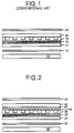
- the visual angle of the LCD is described with reference to FIG. 1 below.
- a conventional LCD includes a back light unit 10 for generating and uniformly supplying a light beam.
- a lower polarizer 12 arranged above the back light unit 10 changes a polarization characteristic of the light beam.
- a lower substrate 14 is arranged above the lower polarizer 12 and provided with switching devices (not shown) in a matrix for controlling the transmitted amount of the light beam.
- a liquid crystal layer 16 is formed on the lower substrate 14 , and a color filter layer 18 formed on the liquid crystal layer 16 .
- An upper substrate 20 is arranged on the color filter layer 18 , and an upper polarizer 22 , arranged above the upper substrate 20 , converts a polarization characteristic of the light beam.
- the back light unit 10 has a light source for generating a light beam, a light-guide plate for uniformly guiding the light beam generated from the light source into a liquid crystal panel, and a reflective plate positioned under the light-guide plate to reflect a light beam going to the lower surface or the side surface of the light-guide plate toward the liquid crystal panel.
- This configuration allows the uniform progression of the light beam from the back light unit 10 into the liquid crystal panel.
- the light beam is polarized by means of the lower polarizer 12 .
- the polarized light beam passes through a liquid crystal layer 16 controlled by means of the switching devices (not shown), where its polarization direction rotates.
- the light beam having its polarization direction rotated by the liquid crystal layer 16 passes through the color filter layer 18 to yield a color wavelength corresponding to each color filter.
- the light beam realized into the desired color by the color filter layer 18 progresses, via the upper substrate 20 , into the upper polarizer 22 .
- the upper polarizer 22 and the lower polarizer 12 are crossed to be perpendicular to each other.
- the upper polarizer 22 transmits only light having its polarization direction rotated by means of the liquid crystal.
- a basic principle of the TN-mode (twisted nematic mode) LCD is to utilize a polarized light beam (polarized by means of the polarizers) which passes through the liquid crystal so that its polarization direction rotates.
- a polarized light beam polarized by means of the polarizers
- the distance the light beam progresses through the liquid crystal layer 16 becomes very significant.
- equation (1) an effect identical to equation (1) is obtained when the direction of the light is perpendicular to the liquid crystal panel, and the result is a reliable light shut-off.
- the diffusion layer is arranged between the upper substrate and the upper polarizer.
- the diffusion layer is used as a lens array, a lenticular lens sheet and a cholesteric liquid crystal (CLC) can be used.
- the present invention provides, in part, a method of fabricating a hologram diffuser for a liquid crystal display that is adapted to widen the visual angle of the liquid crystal display, and a liquid crystal display device employing the same.
- the present invention provides, in part, a liquid crystal display having a hologram diffuser that is adapted to widen the visual angle of the liquid crystal display.
- a method of fabricating a hologram diffuser for a liquid crystal display includes the steps of forming a resin layer with a desired thickness on an upper substrate, forming a hologram pattern at the resin layer, and forming a smoothing film with a desired thickness on the hologram (resin) layer provided with the hologram pattern.
- a liquid crystal display employing a hologram diffuser includes a hologram layer arranged between an upper substrate and a color filter layer, where the hologram layer is provided with a hologram pattern to diffuse a light beam.
- a smoothing film provided at the upper portion of the hologram layer activates the diffusion of the light beam at the hologram layer.
- FIG. 1 is a sectional view showing the structure of a conventional liquid crystal display.
- FIG. 2 is a sectional view showing the structure of a liquid crystal display employing a hologram diffuser according to an embodiment of the present invention.
- FIG. 3A to FIG. 3F are sectional views for explaining a method of fabricating the hologram diffuser shown in FIG. 2 .
- FIG. 2 shows a liquid crystal display using a hologram diffuser according to an embodiment of the present invention.
- the liquid crystal display includes a back light unit 30 for generating and supplying a uniform light beam.
- a lower polarizer 32 arranged above the back light unit 30 converts the polarization characteristic of the light beam.
- a lower substrate 34 arranged above the lower polarizer 32 is provided with switching devices (not shown) in a matrix for controlling the amount of the light beam which is transmitted.
- a liquid crystal layer 36 is formed on the lower substrate 34 , and a color filter layer 38 is formed on the liquid crystal layer 36 .
- a smoothing film 44 is formed on the color filter layer 38 , and a hologram layer 46 is formed on the smoothing film 44 .
- An upper substrate 40 is arranged on the hologram layer 46 , and an upper polarizer 42 is arranged above the upper substrate 40 to convert a polarization characteristic of the light beam.
- the color filter layer 38 may be formed on the lower substrate 34 , and switching devices (not shown) may be formed on the upper substrate 40 .
- the hologram layer 46 diffuses the polarized light beam. Since the light beam is distributed with uniform diffusion in all orientations by the hologram layer 46 , it is possible to attain a wide visual angle.
- the visual angle is controlled by manipulating the hologram pattern formed at the hologram layer 46 .
- the smoothing film 44 smoothes the surface of the hologram layer 46 and activates the light beam diffusion at the hologram layer 46 .
- the smoothing film 44 has a refractive index different from the hologram layer 46 , where the smoothing film is formed at the opposite portion of the hologram layer 46 .
- the preferable difference between the refractive index n 1 of the hologram layer 46 and the refractive index n 2 of the smoothing film 44 is greater than 0.1. This relationship can also be expressed in the following equation (2):
- the hologram layer 46 is arranged between the upper substrate 40 and the color filter layer 38 to accurately diffuse the light beam and to prevent dimming of the image. As a result, it becomes possible to realize high resolution.
- a liquid crystal display employing a hologram diffuser according to the present invention forms the hologram layer 46 and the smoothing film 44 at the upper substrate 40 , thereby assuring a wide visual angle and realizing high resolution.
- FIGS. 3A to 3F show a method of fabricating a hologram diffuser for an LCD according to an embodiment of the present invention.
- the first step of the method is forming a resin layer 50 with a desired thickness on the substrate 40 , as shown in FIG. 3A .
- the resin layer 50 is formed by coating a 0.5 to 10 ⁇ m layer of resin on the substrate 40 .
- spin coating is employed to apply the resin layer 50 .
- the spin coating method is used for accurate thickness control, but a knife coating method or an extrusion coating method may also be used.
- a thermal hardening resin or an ultraviolet hardening resin may be used for the material of the resin layer.
- the second step is the formation of a hologram pattern on the resin layer 50 .
- the hologram pattern is formed on the resin layer 50 by positioning an original hologram plate 60 at the upper portion of the resin layer 50 as shown in FIG. 3B . Pressure is then applied. A roll pressing method or a plate pressing method is used for the pressing.
- heat or ultraviolet (UV) radiation is irradiated onto the resin layer 50 to cure the resin layer 50 in which the hologram pattern, formed by the original hologram plate 60 , is transcribed.
- UV radiation is irradiated onto the resin layer 50 to cure the resin layer 50 in which the hologram pattern, formed by the original hologram plate 60 , is transcribed.
- the material of the resin layer 50 is a thermal hardening resin
- heat is applied for hardening.
- ultraviolet light ultraviolet light is applied for hardening.
- the transcribed resin layer 50 can be hardened by using heat or ultraviolet light after pressing, and then removing the original hologram plate.
- the hologram layer 46 provided with the hologram pattern is formed by removing the original hologram plate 60 as shown in FIG. 3D .
- the third step entails forming a smoothing film 44 with a desired thickness on the hologram layer 46 provided with the hologram pattern.
- the smoothing film 44 is formed to have a thickness of 0.1 to 5 ⁇ m at the upper portion of the hologram layer 46 using the spin coating method.
- the smoothing film 44 is made from a material having a refractive index difference of more than 0.1 from the hologram layer 46 .
- the fourth step is the formation of color filter layers 70 or thin film transistors (TFTs) on the smoothing film 44 .
- the color filter layers 70 may be formed at the upper portion of the smoothing film 44 .
- TFTs (not shown) may be formed. In this case, known fabrication methods can be used to form the color filters or the TFTs.
- the present invention assures a wide visual angle accompanied by high picture quality.
Abstract
Description
(Δn)Z=λ/2 (1)
wherein Δn represents the refractive index difference between the perpendicular direction and the parallel direction of the incident light (which appears as a complex refraction characteristic of the liquid crystal); Z represents the thickness of the liquid crystal; and λ is the wavelength of light. In this case, an effect identical to equation (1) is obtained when the direction of the light is perpendicular to the liquid crystal panel, and the result is a reliable light shut-off. However, an accurate light shut-off cannot be obtained by the upper perpendicular polarizer because the light path increases when the light runs with an inclination, thereby generating a change in the polarization direction of the light. In order to overcome this problem, the linearity of a light beam must be increased.
|n2−n1|>0.1 (2)
Claims (19)
Priority Applications (1)
| Application Number | Priority Date | Filing Date | Title |
|---|---|---|---|
| US11/179,484 US7283187B2 (en) | 1999-09-21 | 2005-07-13 | Method of fabricating hologram diffuser for liquid crystal display and liquid crystal display device using the same |
Applications Claiming Priority (4)
| Application Number | Priority Date | Filing Date | Title |
|---|---|---|---|
| KR1019990040812A KR100608883B1 (en) | 1999-09-21 | 1999-09-21 | Method of Fabricating Hologram Diffusing Plate for Liquid Crystal Display and Liquid Crystal Display Device Using The Same |
| KRP99-40812 | 1999-09-21 | ||
| US09/667,006 US6963380B1 (en) | 1999-09-21 | 2000-09-21 | Method of fabricating hologram diffuser for liquid crystal display and liquid crystal display device using the same |
| US11/179,484 US7283187B2 (en) | 1999-09-21 | 2005-07-13 | Method of fabricating hologram diffuser for liquid crystal display and liquid crystal display device using the same |
Related Parent Applications (1)
| Application Number | Title | Priority Date | Filing Date |
|---|---|---|---|
| US09/667,006 Continuation US6963380B1 (en) | 1999-09-21 | 2000-09-21 | Method of fabricating hologram diffuser for liquid crystal display and liquid crystal display device using the same |
Publications (2)
| Publication Number | Publication Date |
|---|---|
| US20050248701A1 US20050248701A1 (en) | 2005-11-10 |
| US7283187B2 true US7283187B2 (en) | 2007-10-16 |
Family
ID=19612557
Family Applications (2)
| Application Number | Title | Priority Date | Filing Date |
|---|---|---|---|
| US09/667,006 Expired - Lifetime US6963380B1 (en) | 1999-09-21 | 2000-09-21 | Method of fabricating hologram diffuser for liquid crystal display and liquid crystal display device using the same |
| US11/179,484 Expired - Lifetime US7283187B2 (en) | 1999-09-21 | 2005-07-13 | Method of fabricating hologram diffuser for liquid crystal display and liquid crystal display device using the same |
Family Applications Before (1)
| Application Number | Title | Priority Date | Filing Date |
|---|---|---|---|
| US09/667,006 Expired - Lifetime US6963380B1 (en) | 1999-09-21 | 2000-09-21 | Method of fabricating hologram diffuser for liquid crystal display and liquid crystal display device using the same |
Country Status (2)
| Country | Link |
|---|---|
| US (2) | US6963380B1 (en) |
| KR (1) | KR100608883B1 (en) |
Cited By (1)
| Publication number | Priority date | Publication date | Assignee | Title |
|---|---|---|---|---|
| US11487151B2 (en) * | 2019-08-29 | 2022-11-01 | Hefei Boe Display Technology Co., Ltd. | Liquid crystal display panel and display device |
Families Citing this family (10)
| Publication number | Priority date | Publication date | Assignee | Title |
|---|---|---|---|---|
| KR100404161B1 (en) * | 2001-05-03 | 2003-11-03 | 엘지.필립스 엘시디 주식회사 | Transmissive Liquid Crystal Display Device having Hologram Diffuser |
| KR100860240B1 (en) * | 2001-11-13 | 2008-09-25 | 삼성전자주식회사 | Liquid crystal display device having a light refraction portion |
| KR100850472B1 (en) * | 2002-07-05 | 2008-08-07 | 엘지디스플레이 주식회사 | Clone machine for holographic diffuser with a UV curing machine |
| KR100811645B1 (en) * | 2002-07-12 | 2008-03-11 | 엘지.필립스 엘시디 주식회사 | Liquid Crystal Display Device having a Hologram Diffuser |
| KR100883096B1 (en) * | 2002-10-05 | 2009-02-11 | 삼성전자주식회사 | Optical member and method for fabricating the same and liquid crystal display device using the same |
| KR100962495B1 (en) * | 2002-12-28 | 2010-06-14 | 엘지디스플레이 주식회사 | Method and apparatus for fabrication of liquid crystal display module |
| US7612942B2 (en) * | 2006-01-04 | 2009-11-03 | Guardian Industries Corp. | Optical diffuser having frit based coating with inorganic light diffusing pigments with variable particle size therein |
| US7771103B2 (en) * | 2005-09-20 | 2010-08-10 | Guardian Industries Corp. | Optical diffuser with IR and/or UV blocking coating |
| US7446939B2 (en) * | 2005-12-22 | 2008-11-04 | Guardian Industries Corp. | Optical diffuser with UV blocking coating using inorganic materials for blocking UV |
| US7911699B2 (en) * | 2005-12-22 | 2011-03-22 | Guardian Industries Corp. | Optical diffuser with UV blocking coating |
Citations (9)
| Publication number | Priority date | Publication date | Assignee | Title |
|---|---|---|---|---|
| US4856857A (en) * | 1985-05-07 | 1989-08-15 | Dai Nippon Insatsu Kabushiki Kaisha | Transparent reflection-type |
| US5471327A (en) | 1993-05-14 | 1995-11-28 | Kaiser Optical Systems, Inc. | Holographic diffuser for back-lit display |
| US5629784A (en) | 1994-04-12 | 1997-05-13 | Ois Optical Imaging Systems, Inc. | Liquid crystal display with holographic diffuser and prism sheet on viewer side |
| US5631754A (en) * | 1995-10-20 | 1997-05-20 | Physical Optics Corporation | Holographic high contrast viewing screen embedded in a liquid crystal display |
| US6028651A (en) * | 1993-12-15 | 2000-02-22 | Ois Optical Imaging Systems, Inc. | Normally white twisted nematic liquid crystal display including retardation films for improving viewing characteristics |
| US6075581A (en) | 1996-05-31 | 2000-06-13 | Sony Corporation | Liquid crystal display device including a birefringent filter and a diffractive filter for diffusing the resultant image |
| US6141123A (en) | 1998-05-29 | 2000-10-31 | Denso Corporation | Hologram and process for producing hologram |
| US6432498B1 (en) | 1998-04-10 | 2002-08-13 | Dai Nippon Printing Co., Ltd. | Volume hologram laminate |
| US6590605B1 (en) * | 1998-10-14 | 2003-07-08 | Dimension Technologies, Inc. | Autostereoscopic display |
Family Cites Families (6)
| Publication number | Priority date | Publication date | Assignee | Title |
|---|---|---|---|---|
| DE69034082T2 (en) * | 1989-03-16 | 2004-04-01 | Dai Nippon Printing Co., Ltd. | Manufacturing and reproduction processes for filters, and processes for manufacturing photographic filter materials |
| JP3700948B2 (en) * | 1995-11-30 | 2005-09-28 | 大日本印刷株式会社 | Liquid crystal display device using hologram |
| JPH1068946A (en) * | 1996-08-26 | 1998-03-10 | Asahi Glass Co Ltd | Liquid crystal display device |
| JPH10288774A (en) * | 1997-04-15 | 1998-10-27 | Dainippon Printing Co Ltd | Liquid crystal display device using diffuse reflection type hologram |
| KR100255593B1 (en) * | 1997-08-29 | 2000-05-01 | 구본준 | Liquid crystal display |
| JPH1184372A (en) * | 1997-09-05 | 1999-03-26 | Toppan Printing Co Ltd | Reflection type liquid crystal display device |
-
1999
- 1999-09-21 KR KR1019990040812A patent/KR100608883B1/en active IP Right Grant
-
2000
- 2000-09-21 US US09/667,006 patent/US6963380B1/en not_active Expired - Lifetime
-
2005
- 2005-07-13 US US11/179,484 patent/US7283187B2/en not_active Expired - Lifetime
Patent Citations (9)
| Publication number | Priority date | Publication date | Assignee | Title |
|---|---|---|---|---|
| US4856857A (en) * | 1985-05-07 | 1989-08-15 | Dai Nippon Insatsu Kabushiki Kaisha | Transparent reflection-type |
| US5471327A (en) | 1993-05-14 | 1995-11-28 | Kaiser Optical Systems, Inc. | Holographic diffuser for back-lit display |
| US6028651A (en) * | 1993-12-15 | 2000-02-22 | Ois Optical Imaging Systems, Inc. | Normally white twisted nematic liquid crystal display including retardation films for improving viewing characteristics |
| US5629784A (en) | 1994-04-12 | 1997-05-13 | Ois Optical Imaging Systems, Inc. | Liquid crystal display with holographic diffuser and prism sheet on viewer side |
| US5631754A (en) * | 1995-10-20 | 1997-05-20 | Physical Optics Corporation | Holographic high contrast viewing screen embedded in a liquid crystal display |
| US6075581A (en) | 1996-05-31 | 2000-06-13 | Sony Corporation | Liquid crystal display device including a birefringent filter and a diffractive filter for diffusing the resultant image |
| US6432498B1 (en) | 1998-04-10 | 2002-08-13 | Dai Nippon Printing Co., Ltd. | Volume hologram laminate |
| US6141123A (en) | 1998-05-29 | 2000-10-31 | Denso Corporation | Hologram and process for producing hologram |
| US6590605B1 (en) * | 1998-10-14 | 2003-07-08 | Dimension Technologies, Inc. | Autostereoscopic display |
Cited By (1)
| Publication number | Priority date | Publication date | Assignee | Title |
|---|---|---|---|---|
| US11487151B2 (en) * | 2019-08-29 | 2022-11-01 | Hefei Boe Display Technology Co., Ltd. | Liquid crystal display panel and display device |
Also Published As
| Publication number | Publication date |
|---|---|
| KR100608883B1 (en) | 2006-08-03 |
| KR20010028533A (en) | 2001-04-06 |
| US20050248701A1 (en) | 2005-11-10 |
| US6963380B1 (en) | 2005-11-08 |
Similar Documents
| Publication | Publication Date | Title |
|---|---|---|
| US7283187B2 (en) | Method of fabricating hologram diffuser for liquid crystal display and liquid crystal display device using the same | |
| KR100827962B1 (en) | liquid crystal display devices and manufacturing method of the same | |
| US7616277B2 (en) | Transflective LCD device having dual thickness color filter | |
| US7495729B2 (en) | Liquid crystal display-specific substrate having a phase difference control function, and liquid crystal display using the same | |
| US5777713A (en) | Liquid crystal display unit with spacers form in the light shielding regions | |
| US7511786B2 (en) | Substrate for reflective liquid crystal display device and reflective liquid crystal display device using the same | |
| US6323926B2 (en) | Vertical alignment mode LCD having two different alignment regions | |
| US7894029B2 (en) | Apparatus for optically arranging surface of alignment film and method for manufacturing liquid crystal display device using the same | |
| US7573552B2 (en) | Transflective liquid crystal display device and method of fabricating the same | |
| JP2004199030A (en) | Semi-transmission/reflection type display device with different pretilt angles | |
| KR20040090463A (en) | Liquid crystal display element and image display device | |
| US6816219B2 (en) | Liquid crystal panel and method for manufacturing same | |
| US5526147A (en) | Polymer dispersed liquid crystal projector with diffraction gratings along liquid crystal electrodes, a variable diaphragm, and an anamorphic lens | |
| JP2000258760A (en) | Liquid crystal display device | |
| JP2002090512A (en) | Reflector and reflection type liquid crystal display device having the reflector | |
| WO2007013313A1 (en) | Transmissive liquid crystal display | |
| JP2000208410A (en) | Aligner, diffuse reflection plate and reflection display | |
| US20090015733A1 (en) | Retardation Film and Projection Display Apparatus | |
| JPH0618865A (en) | Liquid crystal panel and liquid crystal projection type television using the panel | |
| JP2870747B2 (en) | Projection type liquid crystal display | |
| JP4639785B2 (en) | Phase difference plate, liquid crystal panel, projection type liquid crystal display device | |
| JPH11231807A (en) | Reflection type liquid crystal display device | |
| JP2000098361A (en) | Reflection type liquid crystal display device | |
| KR20020053576A (en) | Method of fabricating liquid crystal display device | |
| JP2003005175A (en) | Semitransmissive liquid crystal display device |
Legal Events
| Date | Code | Title | Description |
|---|---|---|---|
| STCF | Information on status: patent grant |
Free format text: PATENTED CASE |
|
| FEPP | Fee payment procedure |
Free format text: PAYOR NUMBER ASSIGNED (ORIGINAL EVENT CODE: ASPN); ENTITY STATUS OF PATENT OWNER: LARGE ENTITY |
|
| AS | Assignment |
Owner name: LG DISPLAY CO., LTD., KOREA, REPUBLIC OF Free format text: CHANGE OF NAME;ASSIGNOR:LG.PHILIPS LCD CO., LTD.;REEL/FRAME:020985/0675 Effective date: 20080304 Owner name: LG DISPLAY CO., LTD.,KOREA, REPUBLIC OF Free format text: CHANGE OF NAME;ASSIGNOR:LG.PHILIPS LCD CO., LTD.;REEL/FRAME:020985/0675 Effective date: 20080304 |
|
| FEPP | Fee payment procedure |
Free format text: PAYOR NUMBER ASSIGNED (ORIGINAL EVENT CODE: ASPN); ENTITY STATUS OF PATENT OWNER: LARGE ENTITY Free format text: PAYER NUMBER DE-ASSIGNED (ORIGINAL EVENT CODE: RMPN); ENTITY STATUS OF PATENT OWNER: LARGE ENTITY |
|
| FPAY | Fee payment |
Year of fee payment: 4 |
|
| FPAY | Fee payment |
Year of fee payment: 8 |
|
| MAFP | Maintenance fee payment |
Free format text: PAYMENT OF MAINTENANCE FEE, 12TH YEAR, LARGE ENTITY (ORIGINAL EVENT CODE: M1553); ENTITY STATUS OF PATENT OWNER: LARGE ENTITY Year of fee payment: 12 |