US7283475B2 - Fractal dimension analysis for data stream isolation - Google Patents
Fractal dimension analysis for data stream isolation Download PDFInfo
- Publication number
- US7283475B2 US7283475B2 US10/264,777 US26477702A US7283475B2 US 7283475 B2 US7283475 B2 US 7283475B2 US 26477702 A US26477702 A US 26477702A US 7283475 B2 US7283475 B2 US 7283475B2
- Authority
- US
- United States
- Prior art keywords
- network
- housdorff
- transmission
- dimension
- chunks
- Prior art date
- Legal status (The legal status is an assumption and is not a legal conclusion. Google has not performed a legal analysis and makes no representation as to the accuracy of the status listed.)
- Active, expires
Links
Images


Classifications
-
- H—ELECTRICITY
- H04—ELECTRIC COMMUNICATION TECHNIQUE
- H04L—TRANSMISSION OF DIGITAL INFORMATION, e.g. TELEGRAPHIC COMMUNICATION
- H04L43/00—Arrangements for monitoring or testing data switching networks
- H04L43/08—Monitoring or testing based on specific metrics, e.g. QoS, energy consumption or environmental parameters
- H04L43/0852—Delays
Definitions
- the present invention relates generally to network traffic analysis, and more specifically, to the monitoring of data transmitted over a wireless or wired network.
- Communication networks typically include a number of interconnected communication devices. Connections among the devices in some communication networks are accomplished through physical wires or optical links. Such networks may be referred to as “wired” networks. Connections among the devices in other communication networks are accomplished through radio, infrared, or other wireless links. Such networks may be referred to as “wireless” networks.
- a packet is a data unit that includes a header portion and a payload portion.
- the header portion includes control information used to route the packet in the network and the payload portion contains the content data the packet is delivering.
- Military applications are one example in which data packets are encrypted before being transmitted. This may include encrypting the payload portion of each packet so that the content of the communication cannot be understood by eavesdroppers.
- Simply encrypting the payload portion of a packet still allows eavesdroppers to examine the packet header information, through which the eavesdropper may extract valuable information. For example, monitoring the flow of traffic patterns to and from network end-nodes (i.e., sources and destinations) along with the quantity of information transmitted between the end-nodes may allow an eavesdropper to gain valuable intelligence information from the wireless network. For example, a sudden burst of wireless network traffic between multiple known enemy tank groups may indicate that the tank groups are about to perform some type of coordinated action.
- routers in a network may encrypt the packet header information before transmitting the packet. Intercepted packets would, thus, have both their payload and header information encrypted, making it difficult for the eavesdropper to monitor traffic flow.
- the wireless network may be configured to support virtual private network (VPN) connections in which the originating and receiving network addresses are encrypted. This type of VPN also makes it difficult for an eavesdropper to monitor traffic flow.
- VPN virtual private network
- Systems and methods consistent with the present invention provide for traffic analysis of network transmissions even when the network transmissions are encrypted.
- One aspect of the invention is directed to a method of analyzing communications in a network.
- the method includes obtaining time of transmission information for chunks of data in the network and calculating differences in times of transmission between successive chunks. Further, the method includes analyzing traffic flow in the network based on the calculated differences in times of transmission.
- a second aspect of the invention is directed to a system for analyzing traffic flow in a network.
- the system comprises at least one network tap configured to passively observe traffic transmission times in the network.
- At least one processor is configured to calculate differences in times of transmission based on the traffic transmission times observed over a predetermined period.
- the system analyzes traffic flow in the network based on the calculated differences in times of transmission.
- Another method consistent with the present invention comprises a number of acts.
- the method comprises receiving chunks of data from a network and generating transmission time differences between the received chunks. Further, based on the generated transmission time differences, the method estimates a Housdorff dimension and analyzes traffic flow in the network based on the estimated Housdorff dimensions.
- FIG. 1 is a block diagram generally illustrating a wired network
- FIG. 2 is a block diagram generally illustrating a wireless network
- FIG. 3 is an exemplary diagram of traffic flow analysis in the networks of FIGS. 1 and 2 ;
- FIG. 4 is a flow chart illustrating operations consistent with the present invention for performing network traffic analysis.
- FIG. 5 is a diagram illustrating an exemplary series of values corresponding to a node in a network observed over a predefined time interval.
- a system monitors traffic flow in a network.
- the system identifies traffic flow by calculating time intervals between successive transmissions in the flow and then characterizes the time differences as a random variable distributed as Fractional Gaussian Noise.
- FIG. 1 is a diagram illustrating an exemplary wired network 100 according to an implementation consistent with the present invention.
- the wired network 100 may include a number of network nodes 110 A . . . 110 G (collectively referred to as nodes 110 ) connected by a number of network links 115 .
- the wired network 100 may also include one or more network wired taps 120 . Although seven nodes 110 and one wired tap 120 are shown connected in a particular configuration, this is purely exemplary.
- Wired network 100 may include any number and configuration of nodes 110 , links 115 , and taps 120 .
- Network nodes 110 may be configured to send and receive information according to a communication protocol, such as TCP/IP. Although not specifically shown, some nodes 110 may be configured to provide a route for information to a specified destination. Other nodes 110 may be configured to send the information according to a previously determined route. The network nodes 110 may communicate via discrete “chunks” of data that are transmitted by “senders” 110 .
- a chunk may be individually detectable or distinguishable (i.e., a listening device, such as tap 120 , may determine when a chunk starts and ends).
- a chunk of data may correspond to a data packet, although a chunk does not necessarily have to exactly correspond to a packet of data.
- a chunk may represent part of a packet (e.g., a fragment or an ATM cell of an AAL5 PDU), or multiple packets (e.g., two packets concatenated).
- Chunks of data may be transmitted by one of sending nodes 110 , for example, by sending node 110 C (a “sender”).
- a wired sender 110 C may be the most recent node 110 to transmit a particular chunk (e.g., node n 3 in FIG. 1 , if the tap 120 intercepts a chunk transmitted to node n 4 ).
- the sender 110 C is not necessarily the node 110 that originated the chunk.
- Network links 115 may include electronic links (e.g., wires or coaxial cables) and optical links (e.g., fiber optic cables). These links 115 may provide a connection between two nodes 110 (e.g., nodes n 1 and n 3 ). It may be possible to physically tap into these links 115 to observe the information carried on them.
- Wired tap 120 is a device that may intercept chunk transmissions on the network 100 .
- Wired tap 120 may include a physical connection to a corresponding link 115 and circuitry to detect chunks of data on the link 115 .
- Wired tap 120 may intercept chunks at a physical layer, a link layer, a network layer, or at higher layers of the network 100 being monitored. The layer at which interceptions occur is within the abilities of those skilled in the art, and may be chosen based on knowledge of, and access to, the network links 115 .
- the tap 120 may include, for example, a transceiver for sensing the chunks of data and may also include other circuitry (e.g., clock circuitry) for determining times of arrival and duration of the chunks.
- the wired tap 120 may include a processor for computing any other information associated with the chunks, such as information (e.g., sending node and/or receiving node) contained within a header of the chunk of data.
- Wired tap 120 may observe traffic on the 115 between nodes n 3 and n 4 . Wired tap 120 may record information about all the chunks that it observes in a “tracefile.”
- a tracefile as used herein, broadly refers to any file, record, or data structure that stores information about the chunks.
- the tracefile may contain a minimum amount of information for each observed chunk. For example, the information may include the time the chunk was seen and the identity of the sender 110 of the chunk.
- the identity of the sender 110 may include, for example, the IP address of an IPsec gateway, the upstream or downstream transmitter on the point-to-point link 115 , or “the same sender 110 as the one that also sent these other chunks.” If available, the tracefile may also include additional information about the length or duration of the chunk, a destination node 110 , or any insight into the contents of the chunk. Other information that may be available is the location of wired tap 120 along the link 115 relative to the nodes 110 at either end of the link 115 .
- Wired tap 120 may not capture all traffic on the link 115 .
- wired tap 120 may occasionally make an error and mistakenly believe it has seen a chunk when no chunk was sent (e.g., due to bit errors on wired network 100 ). If transmissions are missed, false transmissions are detected, or if a sender 110 is misclassified, these events may be viewed as adding noise to the signals generated by the tap 120 .
- Other sources of noise in the signal generated by the tap 120 may include interference from other signals (e.g., packets belonging to another flow, or jitter in timing due to sharing of a bottleneck among multiple flows).
- Wired tap 120 may listen passively and may not participate in the monitored network 100 at the MAC (or higher) layers. In some cases, for example with 802.3 LANs, it is possible for the tap 120 to snoop at the MAC layer and extract some information about higher layer protocols. In the case of SONET networks, however, little or no information may be available about the MAC or higher layer protocols.
- wired network 100 may contain many wired taps 120 , which may be interconnected. Wired taps 120 may work independently using purely local information. Distributed algorithms may allow sharing of information among wired taps 120 . In such a case, wired taps 120 may have a globally synchronized clock that allows information from multiple taps 120 to be combined. A clock resolution of the taps 120 may be finer than the data sampling resolution of the taps 120 , so that information about transmissions (e.g., the start time, duration, inter-transmission gap, and even the presence of short transmissions) is not missed.
- Wired taps 120 may work independently using purely local information. Distributed algorithms may allow sharing of information among wired taps 120 . In such a case, wired taps 120 may have a globally synchronized clock that allows information from multiple taps 120 to be combined. A clock resolution of the taps 120 may be finer than the data sampling resolution of the taps 120 , so that information about transmissions (e.g., the start time, duration, inter-transmission gap
- a tap 120 may store the transmissions that it detects for a sufficient amount of time. For example, the roundtrip time of a transport layer flow cannot be determined if the history that may be stored at tap 120 is less than one roundtrip time. The total volume of data that must be stored depends on the capacity of the link 115 and the maximum roundtrip time of flows seen on the link 115 .
- Taps 120 may assign a unique identifier to each sender 110 , for example, the address of the IPsec gateway. Taps 120 in the network 100 may assign the same unique identifier to any given sender 110 .
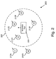
- FIG. 2 is a diagram illustrating an exemplary wireless network 200 according to an implementation consistent with the present invention.
- the wireless network 200 may include a number of wireless nodes 210 A . . . 210 F (collectively referred to as wireless nodes 210 ) and one or more wireless taps 220 .
- the wireless, or mobile, nodes 210 may communicate via wireless transmission, either point-to-point or, more typically, broadcast transmission.
- the wireless tap 220 may have an associated area 225 in which it may be able to intercept wireless transmissions.
- Wireless network 200 may include any number and configuration of nodes 210 and taps 220 .
- the behavior and operation of the wireless nodes 210 and the wireless tap 220 when similar to the network nodes 110 and tap 120 described above, will not be repeated.
- Wireless nodes 210 may communicate via chunks of data that are transmitted by a sender node 210 , for example, node 210 C.
- Sender node 210 C may transmit using various types of wireless physical layers, such as terrestrial RF, satellite bands, and free space optical.
- Nodes n 1 -n 6 may include, for example, radio routers or client radios in the wireless network 200 .
- Wireless tap 220 is a device that may intercept wireless transmissions on wireless network 200 .
- the wireless tap 220 may include, for example, a transceiver for sensing the chunks of data and may also include other circuitry (e.g., clock circuitry) for determining times of arrival and duration of the chunks.
- the wireless tap 220 may include a processor for computing any other information (e.g., the sending or receiving node) associated with the chunks, such as information contained within a header of the chunk of data.
- wireless tap 220 may observe some (potentially very large) fraction of the wireless spectrum and, thus, may see transmissions from a wide range of senders 210 . As shown in FIG.
- wireless tap 220 may have a limited effective reception range.
- Dashed line 225 indicates an effective reception area through which tap 220 may receive communications from the nodes. As shown, nodes n 1 and n 2 are out of the effective reception area and will not be monitored by wireless tap 220 . Nodes n 3 -n 6 , which are within the range 225 , may be monitored by wireless tap 220 .
- Wireless tap 220 may record information about all the chunks that it observes in a tracefile.
- the tracefile may contain a minimum amount of information for each observed chunk.
- the information may include the time the chunk was seen and the identity of the sender 210 of the chunk.
- the identity of the sender 210 may include, for example, the IP address of an IPsec gateway, the location of a radio transmitter 210 , or “the same sender 210 as the one that also sent these other chunks.”
- the tracefile may also include additional information about the length or duration of the chunk, the destination node 210 , or any insight into the contents of the chunk.
- Other information that may be available is the geographic location of the tap 220 , as determined by, for example, a global positioning system (GPS) receiver.
- GPS global positioning system
- Wireless tap 220 may not capture all traffic within its range 225 .
- reception on the wireless network 200 may be variable due to environment, noise, transmission power, or jamming such that wireless tap 220 may be unable to observe some transmissions.
- wireless tap 220 may occasionally make an error and mistakenly believe it has seen a chunk when no chunk was sent (again due to noise on a wireless network). If transmissions are missed, false transmissions are detected, or if a sender 210 is misclassified, these events may be viewed as adding noise to the signals generated by the wireless tap 220 .
- Other sources of noise in the signal generated by the wireless tap 220 may include interference from other signals (e.g., packets belonging to another flow, or jitter in timing due to sharing of a bottleneck among multiple flows).
- Wireless tap 220 may listen passively and may not participate in the monitored network 200 at the MAC (or higher) layers. In some cases, for example with 802.11b LANs, it is possible for the wireless tap 220 to snoop at the MAC layer and extract some information about higher layer protocols. In the case of tactical ad hoc networks, however, little or no information may be available about the MAC or higher layer protocols.
- wireless network 200 may contain many wireless taps 220 , which may be interconnected. In general, the number of wireless taps 220 placed in network 200 is determined by the desired coverage level of network 200 . Wireless taps 220 may work independently using purely local information. Distributed algorithms may allow sharing of information among wireless taps 220 . In such a case, wireless taps 220 may have a globally synchronized clock that allows information from multiple wireless taps 220 to be combined. A clock resolution of the wireless taps 220 may be finer than the data sampling resolution of the wireless taps 220 , so that information about transmissions (e.g., the start time, duration, inter-transmission gap, and even the presence of short transmissions) is not missed.
- a clock resolution of the wireless taps 220 may be finer than the data sampling resolution of the wireless taps 220 , so that information about transmissions (e.g., the start time, duration, inter-transmission gap, and even the presence of short transmissions) is not missed.
- wireless taps 220 may, but need not, be mobile. Wireless taps 220 may be placed randomly over a specified geographic area, or in a pattern. Senders 210 can move into or out of range of one or more wireless taps 220 . Senders 210 typically may dwell in the range of one or more wireless taps 220 long enough for transmissions to be observed, and the sources identified and recorded. Wireless taps 220 may assign a unique identifier to each sender 210 , for example, based on their RF signature, or the address of the IPsec gateway. Wireless taps 220 in the network 200 may assign the same unique identifier to any given sender 210 .
- FIG. 3 is an exemplary diagram of traffic flow analysis and classification processing in networks 100 and 200 . Processing may begin with a tap 120 / 220 obtaining data from its respective network 100 / 200 (act 310 ).
- Either the tap 120 / 220 or an associated (possibly central) processor may perform processing on the data obtained by the tap 120 / 220 to produce results (act 320 ).
- Such signal processing may produce identifiable signal traffic features, and may be computationally intensive.
- Those skilled in the art will appreciate, based on processing and networking requirements, whether to perform the signal processing at each tap 120 / 220 or other location(s).
- the signal processing results may be further processed to analyze and classify the traffic on the network 100 / 200 (act 330 ). Again, such traffic analysis processing may be performed by the tap 120 / 220 or another processor. Acts 310 - 330 may be broadly characterized as “signal generation,” “signal processing,” and “traffic analysis,” respectively. These acts will be described in greater detail for certain implementations below.
- the tap may process the data into a form amenable to traffic analysis or traffic classification.
- FIG. 4 is a flowchart illustrating operations consistent with the present invention for processing a signal into a form amenable to traffic analysis, as performed in signal processing act 320 ( FIG. 3 ).
- a tracefile may represent discrete events, namely a sequence of events associated with different times, such as the time of transmission (TOT) for each received chunk.
- the tracefile may include other information (e.g., sender or recipient information) associated with the events.
- Tap 120 / 220 may begin by calculating differences in successive chunk time of transfers (dTOTs) (act 401 ).
- the TOT values may be stored in the tap's trace file.
- FIG. 5 illustrates a series of chunk TOTs (column 501 ) and a corresponding series of calculated dTOTs (column 502 ).
- the series of values in column 501 is repeatedly measured over a relatively short time interval, such as a time interval on the order of milliseconds. After each time interval, a new TOT series is measured and a corresponding new dTOT series is calculated.
- FIG. 5 illustrates a portion of a TOT series measured over a single time interval.
- the series of dTOT values 502 are assumed to have a random distribution that is distributed as Fractional Gaussian Noise (FGN).
- FGN Fractional Gaussian Noise
- An FGN distribution is parameterized by the Housdorff dimension, H.
- the Housdorff dimension may be calculated using, for example, maximum likelihood estimation techniques.
- FGN distributions and the calculation of the Housdorff dimension using maximum likelihood estimators are well known in the art and will not be described further herein.
- Tap 120 / 220 determines the Housdorff dimension for the calculated series of dTOT values 502 (act 402 ).
- a tap 120 / 220 may estimate the Housdorff dimension of the dTOT values using a maximum likelihood estimator.
- the dTOT values for a time interval and the Housdorff dimension calculated for these values may correspond to chunks from more than one data stream. For example, multiple data streams entering a router may be intermingled in some manner when transmitted as the output data stream. Accordingly, the Housdorff dimension calculated over a particular time interval may represent a composite Housdorff dimension corresponding to a number of component Housdorff dimension values that each represent individual data streams.
- Acts 401 and 402 may be repeated for each successive series of received TOT values (acts 403 and 404 ).
- each series of TOT values may be measured over a relatively short predetermined time interval (e.g., 10 milliseconds). Accordingly, after each time interval, tap 120 / 220 measures the TOT values of the next series of received packets and recalculates the dTOT values.
- Each Housdorff dimension calculated in acts 401 and 402 represents a short time portion of an individual data stream or of a composite data stream.
- the tracefile which associates senders 110 / 210 with the measured TOT values, may thus be used to associate the Housdorff dimensions with the senders 110 / 210 .
- changes in the calculated Housdorff dimension for a composite data stream measured at different taps 120 / 220 may be used to indicate that a component data stream has stopped or started between the taps 120 / 2220 .
- the Housdorff dimensions and their associated senders 110 / 210 may be used by tap 120 / 220 , or other processors, in performing traffic analysis of the data streams in network 100 / 200 (act 405 ). This aspect of the present invention is described below.
- the calculated Housdorff dimensions are used as representations of data streams. Accordingly, by correlating a series of Housdorff dimensions calculated for a number of nodes, the Housdorff dimensions can be used to follow the flow of data in a network. For example, if a first calculated series of Housdorff dimensions is observed at a first node, and the same series of Housdorff dimensions is later observed for a second node, system 100 / 200 may assume that the traffic corresponding to the calculated Housdorff dimensions traveled from the first node to the second node.
- system 100 / 200 may assume that a component data stream has started or stopped transmission at a point between the first and second nodes.
- certain sources may have characteristic Housdorff dimensions that define a “signature” for that source or that type of communication.
- Tap 120 / 220 may, thus, analyze its calculated values and classify them as belonging to certain signatures. Classification of signatures is generally understood by those skilled in the signal processing arts.
- Various techniques are known to classify a certain signature into one or more different classes. Generally, these techniques involve training or otherwise developing a number of known signatures, against which a candidate signature may be compared.
- An FGN is characterized by the Housdorff dimension. Housdorff dimensions are calculated over short time periods for a network node based on the series of differences between successive transfer times for that time period. Each calculated Housdorff dimension is used as a representation of the network traffic for the associated measured time period.
- the exemplary processing was primarily described in the context of a single tap 120 / 220 , multiple taps may function in conjunction with one another.
- the multiple taps may transmit their observed information to a central processing node, which may then perform traffic analysis based on the observed information from the taps.
- processing shown in FIG. 4 may be performed by a computer program or software instructions executed on a general-purpose processor (not shown). Where expeditious, some instructions may be performed in parallel on multiple processors.
- the computer program or software instructions may be embodied on a computer-readable medium (e.g., magnetic, optical, semiconductor, etc.) that is readable by the general-purpose processor.
- FIG. 4 need not be implemented in the order shown; nor do all of the acts need to be performed. Also, those acts which are not dependent on other acts may be performed in parallel with the other acts.
Abstract
Description
Claims (31)
Priority Applications (1)
| Application Number | Priority Date | Filing Date | Title |
|---|---|---|---|
| US10/264,777 US7283475B2 (en) | 2001-10-19 | 2002-10-04 | Fractal dimension analysis for data stream isolation |
Applications Claiming Priority (6)
| Application Number | Priority Date | Filing Date | Title |
|---|---|---|---|
| US11200101A | 2001-10-19 | 2001-10-19 | |
| US10/167,620 US7170860B2 (en) | 2000-10-23 | 2001-10-19 | Method and system for passively analyzing communication data based on frequency analysis of encrypted data traffic, and method and system for deterring passive analysis of communication data |
| US33949701P | 2001-10-26 | 2001-10-26 | |
| US34077901P | 2001-10-30 | 2001-10-30 | |
| US35557302P | 2002-02-05 | 2002-02-05 | |
| US10/264,777 US7283475B2 (en) | 2001-10-19 | 2002-10-04 | Fractal dimension analysis for data stream isolation |
Related Parent Applications (2)
| Application Number | Title | Priority Date | Filing Date |
|---|---|---|---|
| US10/167,620 Continuation-In-Part US7170860B2 (en) | 2000-10-23 | 2001-10-19 | Method and system for passively analyzing communication data based on frequency analysis of encrypted data traffic, and method and system for deterring passive analysis of communication data |
| US11200101A Continuation-In-Part | 2001-10-19 | 2001-10-19 |
Publications (2)
| Publication Number | Publication Date |
|---|---|
| US20030076782A1 US20030076782A1 (en) | 2003-04-24 |
| US7283475B2 true US7283475B2 (en) | 2007-10-16 |
Family
ID=27493835
Family Applications (1)
| Application Number | Title | Priority Date | Filing Date |
|---|---|---|---|
| US10/264,777 Active 2024-09-27 US7283475B2 (en) | 2001-10-19 | 2002-10-04 | Fractal dimension analysis for data stream isolation |
Country Status (1)
| Country | Link |
|---|---|
| US (1) | US7283475B2 (en) |
Cited By (7)
| Publication number | Priority date | Publication date | Assignee | Title |
|---|---|---|---|---|
| US20090187653A1 (en) * | 2008-01-23 | 2009-07-23 | The Chinese University Of Hong Kong | Systems and processes of identifying p2p applications based on behavioral signatures |
| US7574597B1 (en) | 2001-10-19 | 2009-08-11 | Bbn Technologies Corp. | Encoding of signals to facilitate traffic analysis |
| US10420072B2 (en) | 2013-03-14 | 2019-09-17 | Everactive, Inc. | Methods and apparatus for low power wireless communication |
| US10667214B2 (en) | 2013-03-14 | 2020-05-26 | Everactive Inc. | Methods and apparatus for wireless communication via a predefined sequence of a change of a characteristic of a wireless signal |
| US11044009B2 (en) | 2013-03-14 | 2021-06-22 | Everactive, Inc. | Methods and apparatus for networking using a proxy device and backchannel communication |
| US11146299B2 (en) | 2019-09-09 | 2021-10-12 | Everactive, Inc. | Wireless receiver apparatus and method |
| US11758480B2 (en) | 2020-02-14 | 2023-09-12 | Everactive Inc. | Method and system for low power and secure wake-up radio |
Families Citing this family (3)
| Publication number | Priority date | Publication date | Assignee | Title |
|---|---|---|---|---|
| US7983419B2 (en) * | 2001-08-09 | 2011-07-19 | Trimble Navigation Limited | Wireless device to network server encryption |
| US9178597B2 (en) * | 2008-01-28 | 2015-11-03 | Broadcom Corporation | Method of updating transmission channel information based on eaves-dropping of beamformed signals |
| US9973521B2 (en) * | 2015-12-28 | 2018-05-15 | International Business Machines Corporation | System and method for field extraction of data contained within a log stream |
Citations (26)
| Publication number | Priority date | Publication date | Assignee | Title |
|---|---|---|---|---|
| US5793762A (en) | 1994-04-12 | 1998-08-11 | U S West Technologies, Inc. | System and method for providing packet data and voice services to mobile subscribers |
| US5838919A (en) | 1996-09-10 | 1998-11-17 | Ganymede Software, Inc. | Methods, systems and computer program products for endpoint pair based communications network performance testing |
| US5859979A (en) | 1993-11-24 | 1999-01-12 | Intel Corporation | System for negotiating conferencing capabilities by selecting a subset of a non-unique set of conferencing capabilities to specify a unique set of conferencing capabilities |
| US5881237A (en) | 1996-09-10 | 1999-03-09 | Ganymede Software, Inc. | Methods, systems and computer program products for test scenario based communications network performance testing |
| US5999563A (en) | 1996-05-09 | 1999-12-07 | Texas Instruments Incorporated | Rate negotiation for variable-rate digital subscriber line signaling |
| US6021158A (en) | 1996-05-09 | 2000-02-01 | Texas Instruments Incorporated | Hybrid wireless wire-line network integration and management |
| US20020032871A1 (en) | 2000-09-08 | 2002-03-14 | The Regents Of The University Of Michigan | Method and system for detecting, tracking and blocking denial of service attacks over a computer network |
| US20020039371A1 (en) * | 2000-05-18 | 2002-04-04 | Kaynam Hedayat | IP packet identification method and system for TCP connection and UDP stream |
| US20020112060A1 (en) | 2001-02-15 | 2002-08-15 | Kei Kato | Network management system |
| US20020150102A1 (en) | 2001-04-17 | 2002-10-17 | Bozidar Janko | Streaming media quality analyzer system |
| US6484203B1 (en) | 1998-11-09 | 2002-11-19 | Sri International, Inc. | Hierarchical event monitoring and analysis |
| US20030023918A1 (en) * | 2001-04-17 | 2003-01-30 | Wu William W. | Forward error correction techniques |
| US6519703B1 (en) | 2000-04-14 | 2003-02-11 | James B. Joyce | Methods and apparatus for heuristic firewall |
| US6546017B1 (en) | 1999-03-05 | 2003-04-08 | Cisco Technology, Inc. | Technique for supporting tiers of traffic priority levels in a packet-switched network |
| US6546834B1 (en) * | 1997-12-24 | 2003-04-15 | Giben Impianti S.P.A. | Method and machine for sawing panels with laterally movable pusher |
| US6597661B1 (en) | 1999-08-25 | 2003-07-22 | Watchguard Technologies, Inc. | Network packet classification |
| US6662223B1 (en) * | 1999-07-01 | 2003-12-09 | Cisco Technology, Inc. | Protocol to coordinate network end points to measure network latency |
| US6700895B1 (en) | 2000-03-15 | 2004-03-02 | 3Com Corporation | Method and system for computationally efficient calculation of frame loss rates over an array of virtual buffers |
| US20040057376A1 (en) * | 2000-02-08 | 2004-03-25 | Gyorgy Sasvari | Communications system |
| US6718395B1 (en) | 2000-10-10 | 2004-04-06 | Computer Access Technology Corporation | Apparatus and method using an inquiry response for synchronizing to a communication network |
| US6950404B2 (en) * | 2001-05-14 | 2005-09-27 | Dataradio Inc. | Adaptive duty cycle management method and system for radio transmitters |
| US6958977B1 (en) | 2000-06-06 | 2005-10-25 | Viola Networks Ltd | Network packet tracking |
| US6977942B2 (en) * | 1999-12-30 | 2005-12-20 | Nokia Corporation | Method and a device for timing the processing of data packets |
| US6981158B1 (en) | 2000-06-19 | 2005-12-27 | Bbnt Solutions Llc | Method and apparatus for tracing packets |
| US7012893B2 (en) * | 2001-06-12 | 2006-03-14 | Smartpackets, Inc. | Adaptive control of data packet size in networks |
| US20060067245A1 (en) * | 2001-05-14 | 2006-03-30 | Dataradio Inc. | Adaptive duty cycle management method and system for radio transmitters |
-
2002
- 2002-10-04 US US10/264,777 patent/US7283475B2/en active Active
Patent Citations (27)
| Publication number | Priority date | Publication date | Assignee | Title |
|---|---|---|---|---|
| US5859979A (en) | 1993-11-24 | 1999-01-12 | Intel Corporation | System for negotiating conferencing capabilities by selecting a subset of a non-unique set of conferencing capabilities to specify a unique set of conferencing capabilities |
| US5793762A (en) | 1994-04-12 | 1998-08-11 | U S West Technologies, Inc. | System and method for providing packet data and voice services to mobile subscribers |
| US5999563A (en) | 1996-05-09 | 1999-12-07 | Texas Instruments Incorporated | Rate negotiation for variable-rate digital subscriber line signaling |
| US6021158A (en) | 1996-05-09 | 2000-02-01 | Texas Instruments Incorporated | Hybrid wireless wire-line network integration and management |
| US5838919A (en) | 1996-09-10 | 1998-11-17 | Ganymede Software, Inc. | Methods, systems and computer program products for endpoint pair based communications network performance testing |
| US5881237A (en) | 1996-09-10 | 1999-03-09 | Ganymede Software, Inc. | Methods, systems and computer program products for test scenario based communications network performance testing |
| US6546834B1 (en) * | 1997-12-24 | 2003-04-15 | Giben Impianti S.P.A. | Method and machine for sawing panels with laterally movable pusher |
| US6484203B1 (en) | 1998-11-09 | 2002-11-19 | Sri International, Inc. | Hierarchical event monitoring and analysis |
| US6546017B1 (en) | 1999-03-05 | 2003-04-08 | Cisco Technology, Inc. | Technique for supporting tiers of traffic priority levels in a packet-switched network |
| US6662223B1 (en) * | 1999-07-01 | 2003-12-09 | Cisco Technology, Inc. | Protocol to coordinate network end points to measure network latency |
| US6597661B1 (en) | 1999-08-25 | 2003-07-22 | Watchguard Technologies, Inc. | Network packet classification |
| US6977942B2 (en) * | 1999-12-30 | 2005-12-20 | Nokia Corporation | Method and a device for timing the processing of data packets |
| US20040057376A1 (en) * | 2000-02-08 | 2004-03-25 | Gyorgy Sasvari | Communications system |
| US6700895B1 (en) | 2000-03-15 | 2004-03-02 | 3Com Corporation | Method and system for computationally efficient calculation of frame loss rates over an array of virtual buffers |
| US6519703B1 (en) | 2000-04-14 | 2003-02-11 | James B. Joyce | Methods and apparatus for heuristic firewall |
| US20020039371A1 (en) * | 2000-05-18 | 2002-04-04 | Kaynam Hedayat | IP packet identification method and system for TCP connection and UDP stream |
| US6958977B1 (en) | 2000-06-06 | 2005-10-25 | Viola Networks Ltd | Network packet tracking |
| US6981158B1 (en) | 2000-06-19 | 2005-12-27 | Bbnt Solutions Llc | Method and apparatus for tracing packets |
| US20020032871A1 (en) | 2000-09-08 | 2002-03-14 | The Regents Of The University Of Michigan | Method and system for detecting, tracking and blocking denial of service attacks over a computer network |
| US6718395B1 (en) | 2000-10-10 | 2004-04-06 | Computer Access Technology Corporation | Apparatus and method using an inquiry response for synchronizing to a communication network |
| US20020112060A1 (en) | 2001-02-15 | 2002-08-15 | Kei Kato | Network management system |
| US20030023918A1 (en) * | 2001-04-17 | 2003-01-30 | Wu William W. | Forward error correction techniques |
| US6601208B2 (en) * | 2001-04-17 | 2003-07-29 | William W. Wu | Forward error correction techniques |
| US20020150102A1 (en) | 2001-04-17 | 2002-10-17 | Bozidar Janko | Streaming media quality analyzer system |
| US6950404B2 (en) * | 2001-05-14 | 2005-09-27 | Dataradio Inc. | Adaptive duty cycle management method and system for radio transmitters |
| US20060067245A1 (en) * | 2001-05-14 | 2006-03-30 | Dataradio Inc. | Adaptive duty cycle management method and system for radio transmitters |
| US7012893B2 (en) * | 2001-06-12 | 2006-03-14 | Smartpackets, Inc. | Adaptive control of data packet size in networks |
Non-Patent Citations (17)
| Title |
|---|
| Abry et al., "Multiscale Nature of Network Traffic," IEEE Signal Processing Magazine, pp. 28-46, (2002). |
| Boufaden et al., "Topic Segmentation: A First Stage to Dialog-Based Information Extraction," Department of Computer Science and Operations Research, University of Montreal, Quebec, Canada, 7 pages. |
| Cappe et al., "Long-Range Dependence and Heavy-Tail Modeling for Teletraffic Data," IEEE Signal Processing Magazine, pp. 14-27, (2002). |
| Co-pending U.S. Appl. No. 09/881,145, filed Jun. 14, 2001. |
| Co-pending U.S. Appl. No. 10/044,073, filed Jan. 11, 2002. |
| Guerin et al., "A Unified Approach to Bandwidth Allocation and Access Control in Fast Packet-Switched Networks," IEEE INFOCOM, pp. 1-12, (1992). |
| Hazen et al., "Recent Improvements in an Approach to Segment-Based Automatic Language identification," Spoken Language Systems Group, Laboratory for Computer Science, Massachusetts Institute of Technology, Cambridge, MA, 4 pages. |
| James Gordon, Parto Process as a model of self-similar packet traffic, May 1995 IEEE, pp. 2232-2236. * |
| Kay, S.M. "Modern Spectral Estimation: Theory & Application," Prentice Hall, (1988). |
| Oppenheim et al., "Discrete-Time Signal Processing," Prentice Hall, (1989). |
| Parekh, A.K., "A Generalized Processor Sharing Approach to Flow Control in Integrated Services Networks," MIT Ph.D. Thesis, (Feb. 1992). |
| Partridge, C., "Gigabit Networking," Addison-Wesley, (1994). |
| Ramus et al., "Language Identification with Suprasegmental Cues: A Study based on Speech Resynthesis," Journal of the Acoustical Society of America, 105(1):512-521, (1999). |
| Savage et al., "Practical Network Support for IP Traceback," Department of Computer Science and Engineering, University of Washington, Seattle, WA, 12 pages. |
| Schwartz et al., "Smart Packets: Applying Active Networks to Network Management," ACM Transaction on Computer Systems, 18(1):67-88, (2000). |
| Tagliaferri et al., "Hybrid Neural networks for Frequency Estimation of Unevenly Sampled Data," IEEE, pp. 975-979, (1999). |
| Turner, Jonathan, "New Directions in Communications (or Which Way to the Information Age!)," IEEE Communications Magazine, 24(10):8-15, (Oct. 1986). |
Cited By (9)
| Publication number | Priority date | Publication date | Assignee | Title |
|---|---|---|---|---|
| US7574597B1 (en) | 2001-10-19 | 2009-08-11 | Bbn Technologies Corp. | Encoding of signals to facilitate traffic analysis |
| US20090187653A1 (en) * | 2008-01-23 | 2009-07-23 | The Chinese University Of Hong Kong | Systems and processes of identifying p2p applications based on behavioral signatures |
| US7904597B2 (en) | 2008-01-23 | 2011-03-08 | The Chinese University Of Hong Kong | Systems and processes of identifying P2P applications based on behavioral signatures |
| US10420072B2 (en) | 2013-03-14 | 2019-09-17 | Everactive, Inc. | Methods and apparatus for low power wireless communication |
| US10667214B2 (en) | 2013-03-14 | 2020-05-26 | Everactive Inc. | Methods and apparatus for wireless communication via a predefined sequence of a change of a characteristic of a wireless signal |
| US11044009B2 (en) | 2013-03-14 | 2021-06-22 | Everactive, Inc. | Methods and apparatus for networking using a proxy device and backchannel communication |
| US11146299B2 (en) | 2019-09-09 | 2021-10-12 | Everactive, Inc. | Wireless receiver apparatus and method |
| US11689230B2 (en) | 2019-09-09 | 2023-06-27 | Everactive, Inc. | Wireless receiver apparatus and method |
| US11758480B2 (en) | 2020-02-14 | 2023-09-12 | Everactive Inc. | Method and system for low power and secure wake-up radio |
Also Published As
| Publication number | Publication date |
|---|---|
| US20030076782A1 (en) | 2003-04-24 |
Similar Documents
| Publication | Publication Date | Title |
|---|---|---|
| US7917953B2 (en) | Methods and systems for reducing the spread of files on a network | |
| US8433788B2 (en) | Overlay network traffic detection, monitoring, and control | |
| Gerhards-Padilla et al. | Detecting black hole attacks in tactical MANETs using topology graphs | |
| Goher et al. | Covert channel detection: A survey based analysis | |
| JP2007184799A (en) | Packet communication device | |
| US8125898B1 (en) | Method and system for detecting attack path connections in a computer network using state-space correlation | |
| US7283475B2 (en) | Fractal dimension analysis for data stream isolation | |
| US7854003B1 (en) | Method and system for aggregating algorithms for detecting linked interactive network connections | |
| Patel et al. | Wormhole attack detection in wireless sensor network | |
| US7359966B2 (en) | Methods and systems for passive information discovery using Lomb periodogram processing | |
| Zhang et al. | Onis: Inferring tcp/ip-based trust relationships completely off-path | |
| Shree et al. | Wormhole attack in wireless sensor network | |
| Islam et al. | Determining proximal geolocation of IoT edge devices via covert channel | |
| US20030084148A1 (en) | Methods and systems for passive information discovery using cross spectral density and coherence processing | |
| Li et al. | A case study of ipv6 network performance: Packet delay, loss, and reordering | |
| US7318105B1 (en) | Dynamically detecting topology and egress nodes in communication networks | |
| Alsemairi et al. | Adaptive packet-combining to counter traffic analysis in wireless sensor networks | |
| Blaze et al. | Anonymity in wireless broadcast networks | |
| US7200656B1 (en) | Methods and systems for simultaneously detecting short and long term periodicity for traffic flow identification | |
| Blaze et al. | WAR: Wireless anonymous routing | |
| US7574597B1 (en) | Encoding of signals to facilitate traffic analysis | |
| An et al. | Wormhole detection using encrypted node IDs and hop counts in the event report of statistical en-route filtering | |
| US8468234B1 (en) | Methods and systems for tracking file routing on a network | |
| Kai et al. | DDoS scouter: A simple IP traceback scheme | |
| Nesterenkov et al. | Delay Analysis of Massive Unsourced ALOHA-based Protocols with User Authentication |
Legal Events
| Date | Code | Title | Description |
|---|---|---|---|
| AS | Assignment |
Owner name: BBNT SOLUTIONS LLC, MASSACHUSETTS Free format text: ASSIGNMENT OF ASSIGNORS INTEREST;ASSIGNORS:FORTIN, CHRISTOPHER S.;COUSINS, DAVID B.;REEL/FRAME:013374/0023;SIGNING DATES FROM 20020930 TO 20021001 |
|
| AS | Assignment |
Owner name: FLEET NATIONAL BANK, AS AGENT, MASSACHUSETTS Free format text: PATENT & TRADEMARK SECURITY AGREEMENT;ASSIGNOR:BBNT SOLUTIONS LLC;REEL/FRAME:014624/0196 Effective date: 20040326 Owner name: FLEET NATIONAL BANK, AS AGENT,MASSACHUSETTS Free format text: PATENT & TRADEMARK SECURITY AGREEMENT;ASSIGNOR:BBNT SOLUTIONS LLC;REEL/FRAME:014624/0196 Effective date: 20040326 |
|
| AS | Assignment |
Owner name: BBN TECHNOLOGIES CORP.,MASSACHUSETTS Free format text: MERGER;ASSIGNOR:BBNT SOLUTIONS LLC;REEL/FRAME:017274/0318 Effective date: 20060103 Owner name: BBN TECHNOLOGIES CORP., MASSACHUSETTS Free format text: MERGER;ASSIGNOR:BBNT SOLUTIONS LLC;REEL/FRAME:017274/0318 Effective date: 20060103 |
|
| STCF | Information on status: patent grant |
Free format text: PATENTED CASE |
|
| AS | Assignment |
Owner name: BBN TECHNOLOGIES CORP. (AS SUCCESSOR BY MERGER TO Free format text: RELEASE OF SECURITY INTEREST;ASSIGNOR:BANK OF AMERICA, N.A. (SUCCESSOR BY MERGER TO FLEET NATIONAL BANK);REEL/FRAME:023427/0436 Effective date: 20091026 |
|
| AS | Assignment |
Owner name: RAYTHEON BBN TECHNOLOGIES CORP.,MASSACHUSETTS Free format text: CHANGE OF NAME;ASSIGNOR:BBN TECHNOLOGIES CORP.;REEL/FRAME:024456/0537 Effective date: 20091027 Owner name: RAYTHEON BBN TECHNOLOGIES CORP., MASSACHUSETTS Free format text: CHANGE OF NAME;ASSIGNOR:BBN TECHNOLOGIES CORP.;REEL/FRAME:024456/0537 Effective date: 20091027 |
|
| FPAY | Fee payment |
Year of fee payment: 4 |
|
| FPAY | Fee payment |
Year of fee payment: 8 |
|
| MAFP | Maintenance fee payment |
Free format text: PAYMENT OF MAINTENANCE FEE, 12TH YEAR, LARGE ENTITY (ORIGINAL EVENT CODE: M1553); ENTITY STATUS OF PATENT OWNER: LARGE ENTITY Year of fee payment: 12 |