US7285122B2 - Method and apparatus for resecting a distal femur and a proximal tibia in preparation for implementing a partial knee prosthesis - Google Patents
Method and apparatus for resecting a distal femur and a proximal tibia in preparation for implementing a partial knee prosthesis Download PDFInfo
- Publication number
- US7285122B2 US7285122B2 US10/462,174 US46217403A US7285122B2 US 7285122 B2 US7285122 B2 US 7285122B2 US 46217403 A US46217403 A US 46217403A US 7285122 B2 US7285122 B2 US 7285122B2
- Authority
- US
- United States
- Prior art keywords
- resecting
- resector
- spacer
- proximal tibia
- distal femur
- Prior art date
- Legal status (The legal status is an assumption and is not a legal conclusion. Google has not performed a legal analysis and makes no representation as to the accuracy of the status listed.)
- Expired - Fee Related, expires
Links
Images


Classifications
-
- A—HUMAN NECESSITIES
- A61—MEDICAL OR VETERINARY SCIENCE; HYGIENE
- A61B—DIAGNOSIS; SURGERY; IDENTIFICATION
- A61B17/00—Surgical instruments, devices or methods, e.g. tourniquets
- A61B17/14—Surgical saws ; Accessories therefor
- A61B17/15—Guides therefor
- A61B17/154—Guides therefor for preparing bone for knee prosthesis
-
- A—HUMAN NECESSITIES
- A61—MEDICAL OR VETERINARY SCIENCE; HYGIENE
- A61F—FILTERS IMPLANTABLE INTO BLOOD VESSELS; PROSTHESES; DEVICES PROVIDING PATENCY TO, OR PREVENTING COLLAPSING OF, TUBULAR STRUCTURES OF THE BODY, e.g. STENTS; ORTHOPAEDIC, NURSING OR CONTRACEPTIVE DEVICES; FOMENTATION; TREATMENT OR PROTECTION OF EYES OR EARS; BANDAGES, DRESSINGS OR ABSORBENT PADS; FIRST-AID KITS
- A61F2/00—Filters implantable into blood vessels; Prostheses, i.e. artificial substitutes or replacements for parts of the body; Appliances for connecting them with the body; Devices providing patency to, or preventing collapsing of, tubular structures of the body, e.g. stents
- A61F2/02—Prostheses implantable into the body
- A61F2/30—Joints
- A61F2/38—Joints for elbows or knees
-
- A—HUMAN NECESSITIES
- A61—MEDICAL OR VETERINARY SCIENCE; HYGIENE
- A61B—DIAGNOSIS; SURGERY; IDENTIFICATION
- A61B17/00—Surgical instruments, devices or methods, e.g. tourniquets
- A61B17/14—Surgical saws ; Accessories therefor
- A61B17/15—Guides therefor
- A61B17/154—Guides therefor for preparing bone for knee prosthesis
- A61B17/155—Cutting femur
-
- A—HUMAN NECESSITIES
- A61—MEDICAL OR VETERINARY SCIENCE; HYGIENE
- A61B—DIAGNOSIS; SURGERY; IDENTIFICATION
- A61B17/00—Surgical instruments, devices or methods, e.g. tourniquets
- A61B17/14—Surgical saws ; Accessories therefor
- A61B17/15—Guides therefor
- A61B17/154—Guides therefor for preparing bone for knee prosthesis
- A61B17/157—Cutting tibia
-
- A—HUMAN NECESSITIES
- A61—MEDICAL OR VETERINARY SCIENCE; HYGIENE
- A61F—FILTERS IMPLANTABLE INTO BLOOD VESSELS; PROSTHESES; DEVICES PROVIDING PATENCY TO, OR PREVENTING COLLAPSING OF, TUBULAR STRUCTURES OF THE BODY, e.g. STENTS; ORTHOPAEDIC, NURSING OR CONTRACEPTIVE DEVICES; FOMENTATION; TREATMENT OR PROTECTION OF EYES OR EARS; BANDAGES, DRESSINGS OR ABSORBENT PADS; FIRST-AID KITS
- A61F2/00—Filters implantable into blood vessels; Prostheses, i.e. artificial substitutes or replacements for parts of the body; Appliances for connecting them with the body; Devices providing patency to, or preventing collapsing of, tubular structures of the body, e.g. stents
- A61F2/02—Prostheses implantable into the body
- A61F2/30—Joints
- A61F2/38—Joints for elbows or knees
- A61F2002/3895—Joints for elbows or knees unicompartimental
Definitions
- This invention relates to a method and apparatus for resecting a distal femur and a proximal tibia in preparation for implanting a partial knee prosthesis.
- Partial knee replacement surgery has become relatively common, and according to traditional practice, requires a relatively large incision in the patient in order to realign the patient's leg, remove any diseased bone and cartilage, and provide a proper surface for engagement with the tibial and femoral prostheses which must mate to form the partial knee replacement.
- Such large and complicated incisions increase surgical time and risk and also lengthen patient recovery.
- more recently minimally invasive techniques have become available, which greatly reduce the size of the required incision, thus providing more rapid healing and recovery for the patient.
- the instruments used in minimally invasive surgery clearly must be relatively small and are preferably uncomplicated, due to the space constraints within the knee. Further, these instruments must permit alignment of the knee and the proper preparation of the implant surfaces in order to receive and retain the prostheses.
- the present invention provides a resecting kit which includes multiple spacers, each of which has a different spacing dimension.
- a surgeon selects the appropriate spacer with the amount of correction desired to align the patient's leg and installs the spacer with the spacing dimension between the distal femur and proximal tibia on the side of the knee which is to receive the partial knee prosthesis.
- the spacers have projecting stems, upon which a resector is installed in such a way that the resector may pivot around the stem. The resector is then aligned with the axis selected by the surgeon according to known methods, and is pinned to the femur and proximal tibia.
- a cut is then made in the femur after which the resector is removed while leaving the tibial pins in place, the pins being headless pins.
- a second resector is then installed on the pins to effect the required cut of the tibia.
- Other cuts are made in the femur according to known procedures, and the prostheses are then installed according to known procedures.
- the spacers are relatively easy to install between the proximal tibia and distal femur.
- the spacers include a recess to clear the anterior tibial rise, such that the spacer is fully engaged both with the corresponding condyle and the tibial plateau where the prostheses are to be implanted. Since the spacers have no moving parts, minimal manipulation of the instruments within the saggital plane is required.
- FIG. 1 is a sagittal view of a partial knee prosthesis implanted on the distal femur and proximal tibia of a patient;
- FIGS. 2-5 are side views of spacers used in the surgery resecting the proximal tibia and distal femur to accommodate implantation of the implant illustrated in FIG. 1 ;
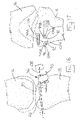
- FIG. 6 is a sagittal view illustrating one of the spacers illustrated in FIGS. 2-5 installed between the distal femur and proximal tibia of a patient undergoing knee replacement surgery;
- FIG. 7 is a posterior view taken along line 7 - 7 of FIG. 6 ;
- FIG. 8 is a sagittal view similar to FIG. 6 but illustrating a resector installed on the spacer illustrated in FIG. 6 ;
- FIG. 9 is an anterior view taken substantially along lines 9 - 9 of FIG. 8 ;
- FIGS. 10 and 11 are views similar to FIGS. 8 and 9 respectively but illustrating an alignment tower installed on the resector illustrated in FIGS. 8 and 9 ;
- FIGS. 12 and 13 are views similar to FIGS. 10 and 11 , but illustrating an alignment rod installed on the alignment tower;
- FIGS. 14 and 15 are views similar to FIGS. 8 and 9 , but illustrating the manner in which the distal femur is resected using the resection kit in the present invention
- FIGS. 16 and 17 are views similar to FIGS. 14 and 15 , but illustrating another resector mounted on the spacer and further illustrating the manner in which the resection is performed;
- FIGS. 18 and 19 are views similar to FIGS. 16 and 17 but illustrating the completed tibial cut and distal femoral cut.
- FIG. 20 is a perspective view of a spacer according to another embodiment.
- FIG. 21 is an anterior view of the spacer of FIG. 20 installed between the distal femur and proximal tibia and having a resector installed on the spacer.
- the present invention relates to a method and apparatus for resecting a femur and tibia and for implanting a partial knee prosthesis, the resection being effected by using a resecting kit.
- the resecting kit includes a set of multiple spacers each having different spacing dimensions to permit the surgeon to adjust the spacing between the proximal tibia and distal femur at the side of the knee which the prosthesis is to be implanted, a pair of resectors for guiding resectioning of the tibia and femur, and other instruments for aligning the leg and preparing the knee for implantation of the partial knee prosthesis.
- a partial knee prosthesis generally indicated by the numeral 10 includes a femoral prosthesis 12 and a tibial prosthesis 14 .
- Femoral prosthesis 12 is implanted upon the distal femur 16
- the tibial prosthesis 14 implanted on the proximal tibial 18 .
- the femur terminates in condyles 20 and 22 . Since the prosthesis 10 may be used to replace either the lateral or medial condyle of the patient, femur 16 and proximal tibia 18 may represent either the right or left leg of the patient.
- the proximal tibia 18 terminates in a tibial plateau 24 bounded in part by the anterior tibial rise 26 .
- a portion of the tibial plateau must be resected to provide a flat surface 28 , which must be drilled in order to accommodate implantation of tibial prosthesis 14 , which is then cemented into place.
- the distal femur must be resected to provide a distal femoral cut forming a surface 30 , a posterior chamfer femoral cut forming a surface 32 , and a posterior femoral cut forming a surface 34 .
- Femoral prosthesis 12 includes anchors (not shown) which are received within holes drilled in one or more of the surfaces 30 , 32 and 34 .
- the present invention relates to a method and apparatus for effecting the resections forming the surfaces 28 and 30 .
- Surfaces 32 and 34 are resected after the resections forming the surfaces 28 and 30 are effected.
- the cuts resulting in surfaces 32 and 34 are made in a conventional manner, such as by temporarily installing a drilling and cutting guide in the prior art on the surface 30 and then making the cuts necessary to form the surfaces 32 and 34 .
- the surfaces 28 and 30 held to as nearly parallel as possible in the lateral/medial plane, and that the surfaces 28 , 30 diverge from each other about 6 degrees-8 degrees in the anterior to posterior plane. It is also necessary to align the patient's leg to correct bow-leggedness or the patient's knock-knees. If the diseased side of the joint is the medial side, the deterioration and the cartilage and any subsequent deterioration of the bone will cause the distance between the corresponding condyle and corresponding portion of the tibial plateau to narrow, resulting in the patient becoming bow-legged. On the other hand, if the diseased portion of the joint is on the lateral side, the patient becomes knock-kneed.
- the method and resection kit of the present invention permits the patient's leg to be straightened without over-correcting, since any over-correction will result in increased wear on the other side of the joint. Furthermore, the method and kit according to the present invention assures proper alignment of the surfaces 28 and 30 .
- each of the spacers 36 A-D include a stem 38 and an arm 40 extending from the stem.
- Small spacer 36 A includes an arm 40 which includes a pair or opposed, substantially flat, parallel surfaces 42 , 44 .
- the spacing dimension of spacer 36 A is the distance between the surfaces 42 and 44 .
- Each of the remaining spacers 36 B-D include an arm 40 A-D having a substantial flat upper surface 42 A with a bump 46 projecting from the surface 44 .
- Each of the bumps 46 are defined by a curved surface 48 for a purpose described hereinafter.
- the spacing dimensions in each of the spacers 36 B-D is the distance between the upper surface 42 and the maximum dimension of the bump 46 .
- Curved surface 48 of the bump 46 cooperates with the surface 44 and transverse end surface 50 of the stem 38 to define a recess 52 therebetween.
- Transversely spaced, longitudinally extending keels 54 are provided on the bumps 46 (see FIG. 7 ).
- the surgeon selects one of the spacers 36 which the surgeon judges will correct the patient's knock-knees or bow-leggedness and properly align the patient's leg.
- the surgeon manipulates the bump 46 (or the flat arm of spacer 36 A) of the selected spacer over the anterior tibial rise 26 so that the anterior tibial rise 26 is received within the recess 52 of the spacer, the curved surface 48 engages the tibial plateau 24 , and the upper flat surface 42 engages the contoured surface 55 of the condyle 20 at its closest approach to the tibial plateau 24 .
- the keels 54 resist movement of the spacer 36 in the lateral-medial direction, but permit movement in the anterior-posterior direction to permit installation of the spacer such that the spacer separates the joint to correct the aforementioned alignment of the patient's leg.
- the surgeon makes a judgment as to whether the patient's leg is properly aligned. If the surgeon decides that a different spacer is needed, the surgeon removes the first selected spacer and selects another spacer for installation between the distal femur 16 and proximal tibia 18 . It will be noted that stem 38 of the selected spacer projects from the joint.
- the resector 56 includes a cylindrical aperture 58 slidably and rotatably engages the stem 38 to permit the resector 56 to pivot about the stem 38 .
- the resector 56 further includes a slot 60 which is adapted to receive the blade of a saw that will effect cutting of the condyle 20 .
- the resector 56 includes multiple apertures 62 , 64 , 66 , 68 , and 70 , which are adapted to receive pins which will be hereinafter described.
- the resector 56 includes a pair of opposed, parallel side edges 72 , 74 .
- an alignment tower generally indicated by the numeral 76 ( FIGS. 10 and 11 ) is installed on the resector 56 .
- the tower 76 includes a bifurcated end 78 including arms 80 that slidably engage the opposite side edges 72 , 74 of the resector 56 .
- the opposite end of the alignment tower 76 carries a cylinder 82 , which projects transversely with respect to the alignment tower 76 .
- a longitudinal opening 83 in alignment tower 76 receives the portion of stem 38 projecting from resector 56 .
- Cylinder 82 defines an opening 84 extending transversely with respect to the alignment tower 76 which receives a longitudinally extending alignment rod 86 .
- the side edges 72 , 74 of resector 56 are perpendicular to the slot 60 in the resector 56 , since the alignment tower 76 maintains the alignment rod 86 parallel to the side edges 72 , 74 , the axis of the alignment rod 86 will accordingly also be perpendicular to the slot 60 .
- the surgeon manipulates the alignment rod 86 , which extends the entire length of the tibia, until the alignment rod 86 extends along an axis desired by the surgeon and which is chosen according to the surgeon's judgment and experience. In most cases, however, the selected axis will approximate the mechanical axis of the tibia. It will be noted that because of the curved surface 48 of the bump 46 , the surgeon may rotate the spacer in the sagittal plane to permit the rod 86 to clear any obstacles, such as any projecting portions of the patient's leg or ankle.
- headed or headless pins are installed in aperture 62 and headless pins are installed into a selected pair of apertures 64 - 70 .
- pin 88 is installed in aperture 62 and pins 90 and 92 are installed in the apertures 64 and 68 .
- the pins 88 - 92 are installed and secured in holes drilled in the distal femur and proximal tibia to thereby secure the resector 56 in place.
- the slot 60 of resector 56 will be perpendicular to the axis selected by the physician.
- a threaded opening 93 is provided which receives an appropriate threaded rod of a tool used to extract the alignment tower 76 .
- a blade 94 of a conventional surgical saw is installed in the slot 60 and effects cutting of the condyle 20 to form the surface 30 . Since the saw is guided by the slot 60 , surface 30 will also be perpendicular to the axis selected by the physician.
- the pin 88 is removed, but the pins 90 and 92 are left in place. Since the pins 90 , 92 are headless pins, the resector 56 may be pulled off of the pins by use of appropriate clamping tool (not shown) engaging the side edges 72 , 74 so that the resector 56 may be pulled off of the pins 90 , 92 . After the surgeon has removed the resector 56 , a second resector 96 is installed on the pins 90 and 92 , care having been taken not to disturb the pins 90 and 92 in any way during the removal of the resector 56 and installation of the resector 96 .
- the resector 96 is provided with a first set of apertures 98 A, 98 B, a second set of apertures 100 A, 100 B, a third set of apertures 102 A, 102 B, and a fourth set of apertures (through which the pins 90 and 92 extend as illustrated in FIGS. 16-17 ) 104 A and 104 B.
- Each of the aperture sets are spaced a distance to conform with the spacing between the pins 90 and 92 , as established by use of the resector 56 as described above.
- the multiple sets of apertures are provided so that the surgeon may select the distance between the tibial cut and the distal femoral cut.
- the resector 96 is also provided with a slot 106 .
- the resector is installed on the pins 90 and 92 and since the resector 96 has been designed with the slot 106 in a pre-established relationship with respect to the slot 60 , the cut formed by the saw blade 108 through the slot 106 has the same relationship to the distal femoral cut 32 . That is, the tibial cut formed by saw blade 108 in slot 106 in the resector 96 will be parallel to the horizontal femoral of surface 32 in the laterally-medial plane, and will have the proper diverging angle in the anterior posterior plane. After the tibial surface 28 is formed, the resector 96 is removed from the pins 90 and 92 .
- the aforementioned fixture (not shown) is mounted on the surface 32 to guide resection of the surfaces 32 , 34 , and to drill the necessary apertures (not shown) to mount the femoral prosthesis 30 .
- a template (not shown) is used to drill the necessary mounting holes in the tibial surface 28 .
- the prostheses 12 and 14 can then be installed according to known procedures.
- a spacer generally indicated by the numeral 110 for setting the spacing between the distal femur and proximal tibia has been selected by the surgeon from a set of spacers similar to the set illustrated in FIGS. 2-5 .
- the stem 38 of the spacers illustrated in FIGS. 2-5 has been replaced on the spacer 110 by a stem 112 having flats 114 , 116 on opposite sides thereof.
- the resector 56 of the embodiment of FIGS. 1-19 has been replaced with a resector 118 in the embodiment of FIGS.
- the resector 118 will not rotate relative to the stem during the alignment procedure but instead will pivot the spacer 110 relative the distal femur and proximal tibia. Since the resector 118 is not rotated relative to the spacer, the surgeon is assured that the cut made by use of the resector 118 is at a predetermined distance from the upper surface 42 of the spacer and is parallel thereto, although the spacing between the distal femur and proximal tibia will be slightly different from that initially established by installation of the spacer 110 . Some surgeons prefer to assure that the size of the cut is confirmed by the resector, even if the spacing between the bones may be affected slightly; accordingly, these surgeons may prefer to use the spacer 110 and resector 118 .
Abstract
Description
Claims (21)
Priority Applications (1)
| Application Number | Priority Date | Filing Date | Title |
|---|---|---|---|
| US10/462,174 US7285122B2 (en) | 2001-06-20 | 2003-06-16 | Method and apparatus for resecting a distal femur and a proximal tibia in preparation for implementing a partial knee prosthesis |
Applications Claiming Priority (2)
| Application Number | Priority Date | Filing Date | Title |
|---|---|---|---|
| US09/885,864 US6632225B2 (en) | 2001-06-20 | 2001-06-20 | Method and apparatus for resecting a distal femur and a proximal tibia in preparation for implanting a partial knee prosthesis |
| US10/462,174 US7285122B2 (en) | 2001-06-20 | 2003-06-16 | Method and apparatus for resecting a distal femur and a proximal tibia in preparation for implementing a partial knee prosthesis |
Related Parent Applications (1)
| Application Number | Title | Priority Date | Filing Date |
|---|---|---|---|
| US09/885,864 Division US6632225B2 (en) | 2001-06-20 | 2001-06-20 | Method and apparatus for resecting a distal femur and a proximal tibia in preparation for implanting a partial knee prosthesis |
Publications (2)
| Publication Number | Publication Date |
|---|---|
| US20030216741A1 US20030216741A1 (en) | 2003-11-20 |
| US7285122B2 true US7285122B2 (en) | 2007-10-23 |
Family
ID=25387856
Family Applications (2)
| Application Number | Title | Priority Date | Filing Date |
|---|---|---|---|
| US09/885,864 Expired - Lifetime US6632225B2 (en) | 2001-06-20 | 2001-06-20 | Method and apparatus for resecting a distal femur and a proximal tibia in preparation for implanting a partial knee prosthesis |
| US10/462,174 Expired - Fee Related US7285122B2 (en) | 2001-06-20 | 2003-06-16 | Method and apparatus for resecting a distal femur and a proximal tibia in preparation for implementing a partial knee prosthesis |
Family Applications Before (1)
| Application Number | Title | Priority Date | Filing Date |
|---|---|---|---|
| US09/885,864 Expired - Lifetime US6632225B2 (en) | 2001-06-20 | 2001-06-20 | Method and apparatus for resecting a distal femur and a proximal tibia in preparation for implanting a partial knee prosthesis |
Country Status (1)
| Country | Link |
|---|---|
| US (2) | US6632225B2 (en) |
Cited By (16)
| Publication number | Priority date | Publication date | Assignee | Title |
|---|---|---|---|---|
| US20040039395A1 (en) * | 2002-05-24 | 2004-02-26 | Coon Thomas M. | Instruments for knee surgery and method of use |
| US20060247647A1 (en) * | 2002-11-27 | 2006-11-02 | Zimmer Technology, Inc. | Method and apparatus for achieving correct limb alignment in unicondylar knee arthroplasty |
| US20100004702A1 (en) * | 2005-11-07 | 2010-01-07 | Howmedica Osteonics Corp. | Tibial Augmentation Guide |
| US20100076487A1 (en) * | 2008-09-23 | 2010-03-25 | Ilahi Omer A | Kit Containing Combination Absorbable Staple and Non-absorbable Suture, And Method Of Using Same |
| US20110276051A1 (en) * | 2010-03-09 | 2011-11-10 | Vot, Llc | Tether and apparatus for performing a bone resection and method of use |
| WO2012154643A3 (en) * | 2011-05-06 | 2013-01-17 | Burroughs Paul Leach Iii | Quadriceps tendon stripper |
| US8663234B2 (en) | 2011-08-01 | 2014-03-04 | Zimmer, Inc. | Combination ligament tensioner and alignment device |
| US8784495B2 (en) | 2000-01-14 | 2014-07-22 | Bonutti Skeletal Innovations Llc | Segmental knee arthroplasty |
| US8834490B2 (en) | 2001-08-28 | 2014-09-16 | Bonutti Skeletal Innovations Llc | Method for robotic arthroplasty using navigation |
| US8894675B2 (en) | 2012-06-11 | 2014-11-25 | Paul Leach Burroughs, III | Tubular ligament cutting implement |
| US8894676B2 (en) | 2012-06-11 | 2014-11-25 | Paul Leach Burroughs, III | Tubular ligament cutting implement |
| US20170333018A1 (en) * | 2014-11-07 | 2017-11-23 | Implantcast Gmbh | A Method and Apparatus for Joint Reconstruction |
| US11376022B2 (en) | 2019-07-18 | 2022-07-05 | Quadvantage Technology, Inc. | Patella cutting guide |
| US11666346B2 (en) | 2007-03-23 | 2023-06-06 | Xiros Limited | Surgical templates |
| WO2024013375A1 (en) | 2022-07-14 | 2024-01-18 | Mathys Ag Bettlach | A device for orienting surgical instruments |
| DE102023104682A1 (en) | 2022-07-14 | 2024-01-25 | Mathys Ag Bettlach | A DEVICE AND METHOD FOR ALIGNING SURGICAL TOOLS |
Families Citing this family (98)
| Publication number | Priority date | Publication date | Assignee | Title |
|---|---|---|---|---|
| US7534263B2 (en) | 2001-05-25 | 2009-05-19 | Conformis, Inc. | Surgical tools facilitating increased accuracy, speed and simplicity in performing joint arthroplasty |
| US8083745B2 (en) * | 2001-05-25 | 2011-12-27 | Conformis, Inc. | Surgical tools for arthroplasty |
| US7468075B2 (en) | 2001-05-25 | 2008-12-23 | Conformis, Inc. | Methods and compositions for articular repair |
| US20020019387A1 (en) * | 1997-09-24 | 2002-02-14 | Smithkline Beecham Corporation | Vitronectin receptor antagonist |
| US6702821B2 (en) | 2000-01-14 | 2004-03-09 | The Bonutti 2003 Trust A | Instrumentation for minimally invasive joint replacement and methods for using same |
| JP5026651B2 (en) * | 2000-03-10 | 2012-09-12 | スミス アンド ネフュー インコーポレーテッド | Device used for knee arthroplasty |
| WO2002096268A2 (en) | 2001-05-25 | 2002-12-05 | Imaging Therapeutics, Inc. | Methods and compositions for articular resurfacing |
| US8951260B2 (en) | 2001-05-25 | 2015-02-10 | Conformis, Inc. | Surgical cutting guide |
| US8439926B2 (en) | 2001-05-25 | 2013-05-14 | Conformis, Inc. | Patient selectable joint arthroplasty devices and surgical tools |
| US7153303B2 (en) * | 2002-06-19 | 2006-12-26 | Sdgi Holdings, Inc. | Guide and blade for contouring vertebral bodies |
| US8551100B2 (en) | 2003-01-15 | 2013-10-08 | Biomet Manufacturing, Llc | Instrumentation for knee resection |
| US7887542B2 (en) | 2003-01-15 | 2011-02-15 | Biomet Manufacturing Corp. | Method and apparatus for less invasive knee resection |
| US7837690B2 (en) | 2003-01-15 | 2010-11-23 | Biomet Manufacturing Corp. | Method and apparatus for less invasive knee resection |
| US7789885B2 (en) | 2003-01-15 | 2010-09-07 | Biomet Manufacturing Corp. | Instrumentation for knee resection |
| EP1470787B1 (en) * | 2003-04-25 | 2006-05-31 | Zimmer GmbH | Device for preparation of a femoral condyle |
| US7306607B2 (en) * | 2003-07-28 | 2007-12-11 | Biomet Manufacturing Corp. | Method and apparatus for minimally invasive distal femoral resection |
| EP1491166B1 (en) | 2003-09-15 | 2005-03-02 | Zimmer GmbH | Adjusting device |
| US8090857B2 (en) * | 2003-11-24 | 2012-01-03 | Qualcomm Atheros, Inc. | Medium access control layer that encapsulates data from a plurality of received data units into a plurality of independently transmittable blocks |
| US7488324B1 (en) | 2003-12-08 | 2009-02-10 | Biomet Manufacturing Corporation | Femoral guide for implanting a femoral knee prosthesis |
| US7641661B2 (en) * | 2003-12-26 | 2010-01-05 | Zimmer Technology, Inc. | Adjustable resection guide |
| JP4932496B2 (en) * | 2004-02-06 | 2012-05-16 | シンバシブ テクノロジー インコーポレイティッド | Dynamic knee balancer |
| US8758355B2 (en) | 2004-02-06 | 2014-06-24 | Synvasive Technology, Inc. | Dynamic knee balancer with pressure sensing |
| US7442196B2 (en) * | 2004-02-06 | 2008-10-28 | Synvasive Technology, Inc. | Dynamic knee balancer |
| US20060089621A1 (en) * | 2004-03-18 | 2006-04-27 | Mike Fard | Bone mill and template |
| US8167888B2 (en) | 2004-08-06 | 2012-05-01 | Zimmer Technology, Inc. | Tibial spacer blocks and femoral cutting guide |
| US20060217734A1 (en) * | 2005-03-09 | 2006-09-28 | Zimmer Technology, Inc. | Femoral resection guide apparatus and method |
| US7695479B1 (en) | 2005-04-12 | 2010-04-13 | Biomet Manufacturing Corp. | Femoral sizer |
| US7780671B2 (en) * | 2006-01-23 | 2010-08-24 | Zimmer Technology, Inc. | Bone resection apparatus and method for knee surgery |
| CA2641241A1 (en) | 2006-02-06 | 2007-08-16 | Conformis, Inc. | Patient selectable joint arthroplasty devices and surgical tools |
| US8623026B2 (en) | 2006-02-06 | 2014-01-07 | Conformis, Inc. | Patient selectable joint arthroplasty devices and surgical tools incorporating anatomical relief |
| US9173661B2 (en) | 2006-02-27 | 2015-11-03 | Biomet Manufacturing, Llc | Patient specific alignment guide with cutting surface and laser indicator |
| US8603180B2 (en) | 2006-02-27 | 2013-12-10 | Biomet Manufacturing, Llc | Patient-specific acetabular alignment guides |
| US8591516B2 (en) | 2006-02-27 | 2013-11-26 | Biomet Manufacturing, Llc | Patient-specific orthopedic instruments |
| US9113971B2 (en) | 2006-02-27 | 2015-08-25 | Biomet Manufacturing, Llc | Femoral acetabular impingement guide |
| US9289253B2 (en) | 2006-02-27 | 2016-03-22 | Biomet Manufacturing, Llc | Patient-specific shoulder guide |
| US9345548B2 (en) | 2006-02-27 | 2016-05-24 | Biomet Manufacturing, Llc | Patient-specific pre-operative planning |
| US9907659B2 (en) | 2007-04-17 | 2018-03-06 | Biomet Manufacturing, Llc | Method and apparatus for manufacturing an implant |
| US9918740B2 (en) | 2006-02-27 | 2018-03-20 | Biomet Manufacturing, Llc | Backup surgical instrument system and method |
| US7780672B2 (en) | 2006-02-27 | 2010-08-24 | Biomet Manufacturing Corp. | Femoral adjustment device and associated method |
| US8407067B2 (en) | 2007-04-17 | 2013-03-26 | Biomet Manufacturing Corp. | Method and apparatus for manufacturing an implant |
| US20150335438A1 (en) | 2006-02-27 | 2015-11-26 | Biomet Manufacturing, Llc. | Patient-specific augments |
| US9339278B2 (en) | 2006-02-27 | 2016-05-17 | Biomet Manufacturing, Llc | Patient-specific acetabular guides and associated instruments |
| US8070752B2 (en) | 2006-02-27 | 2011-12-06 | Biomet Manufacturing Corp. | Patient specific alignment guide and inter-operative adjustment |
| US10278711B2 (en) | 2006-02-27 | 2019-05-07 | Biomet Manufacturing, Llc | Patient-specific femoral guide |
| GB0610572D0 (en) * | 2006-05-27 | 2006-07-05 | Depuy Int Ltd | Guide assembly |
| US7695520B2 (en) | 2006-05-31 | 2010-04-13 | Biomet Manufacturing Corp. | Prosthesis and implementation system |
| US9795399B2 (en) | 2006-06-09 | 2017-10-24 | Biomet Manufacturing, Llc | Patient-specific knee alignment guide and associated method |
| US7686812B2 (en) * | 2006-06-30 | 2010-03-30 | Howmedica Osteonics Corp. | Method for setting the rotational position of a femoral component |
| DE202006014895U1 (en) * | 2006-09-15 | 2006-11-30 | C. & E. Fein Gmbh | Guide device for saw blade has base body with guide slot through it coming out to first guide surface to set against workpiece |
| FR2906125B1 (en) * | 2006-09-27 | 2009-04-17 | Eric Duvillier | TIBIO-FEMORAL RESECTION APPARATUS |
| US7959637B2 (en) | 2007-03-13 | 2011-06-14 | Biomet Manufacturing Corp. | Distal femoral cutting guide |
| US20090018544A1 (en) * | 2007-07-13 | 2009-01-15 | Zimmer, Inc. | Method and apparatus for soft tissue balancing |
| US8265949B2 (en) | 2007-09-27 | 2012-09-11 | Depuy Products, Inc. | Customized patient surgical plan |
| EP2957240A1 (en) | 2007-09-30 | 2015-12-23 | DePuy Products, Inc. | Customized patient-specific orthopaedic surgical instrumentation |
| US8357111B2 (en) | 2007-09-30 | 2013-01-22 | Depuy Products, Inc. | Method and system for designing patient-specific orthopaedic surgical instruments |
| US8197489B2 (en) | 2008-06-27 | 2012-06-12 | Depuy Products, Inc. | Knee ligament balancer |
| US9017334B2 (en) | 2009-02-24 | 2015-04-28 | Microport Orthopedics Holdings Inc. | Patient specific surgical guide locator and mount |
| US8808303B2 (en) | 2009-02-24 | 2014-08-19 | Microport Orthopedics Holdings Inc. | Orthopedic surgical guide |
| US8808297B2 (en) | 2009-02-24 | 2014-08-19 | Microport Orthopedics Holdings Inc. | Orthopedic surgical guide |
| US8551023B2 (en) | 2009-03-31 | 2013-10-08 | Depuy (Ireland) | Device and method for determining force of a knee joint |
| US8740817B2 (en) | 2009-03-31 | 2014-06-03 | Depuy (Ireland) | Device and method for determining forces of a patient's joint |
| US8556830B2 (en) | 2009-03-31 | 2013-10-15 | Depuy | Device and method for displaying joint force data |
| US8597210B2 (en) | 2009-03-31 | 2013-12-03 | Depuy (Ireland) | System and method for displaying joint force data |
| US8721568B2 (en) * | 2009-03-31 | 2014-05-13 | Depuy (Ireland) | Method for performing an orthopaedic surgical procedure |
| SG10201401326SA (en) | 2009-04-16 | 2014-10-30 | Conformis Inc | Patient-specific joint arthroplasty devices for ligament repair |
| US9173743B2 (en) | 2009-07-01 | 2015-11-03 | Biomet Uk Limited | Method of implanting a unicondylar knee prosthesis |
| US8764840B2 (en) | 2010-07-24 | 2014-07-01 | Zimmer, Inc. | Tibial prosthesis |
| CA2806321C (en) | 2010-07-24 | 2018-08-21 | Zimmer, Inc. | Asymmetric tibial components for a knee prosthesis |
| EP3348236B1 (en) | 2010-09-10 | 2019-11-20 | Zimmer, Inc. | Motion facilitating tibial components for a knee prosthesis |
| US9968376B2 (en) | 2010-11-29 | 2018-05-15 | Biomet Manufacturing, Llc | Patient-specific orthopedic instruments |
| US8603101B2 (en) | 2010-12-17 | 2013-12-10 | Zimmer, Inc. | Provisional tibial prosthesis system |
| US9597090B2 (en) | 2010-12-17 | 2017-03-21 | Zimmer, Inc. | Cut guide attachment for use in tibial prosthesis systems |
| US9149206B2 (en) | 2012-03-30 | 2015-10-06 | Zimmer, Inc. | Tibial prosthesis systems, kits, and methods |
| US9241745B2 (en) | 2011-03-07 | 2016-01-26 | Biomet Manufacturing, Llc | Patient-specific femoral version guide |
| GB201115411D0 (en) | 2011-09-07 | 2011-10-19 | Depuy Ireland | Surgical instrument |
| WO2013063043A1 (en) | 2011-10-24 | 2013-05-02 | Synvasive Technology, Inc. | Knee balancing devices, systems and methods |
| WO2013074144A1 (en) | 2011-11-18 | 2013-05-23 | Zimmer, Inc. | Tibial bearing component for a knee prosthesis with improved articular characteristics |
| WO2013077919A1 (en) | 2011-11-21 | 2013-05-30 | Zimmer, Inc. | Tibial baseplate with asymmetric placement of fixation structures |
| EP2809273B1 (en) | 2012-01-30 | 2021-05-05 | Zimmer, Inc. | Asymmetric tibial components for a knee prosthesis |
| US9381011B2 (en) | 2012-03-29 | 2016-07-05 | Depuy (Ireland) | Orthopedic surgical instrument for knee surgery |
| US10206792B2 (en) | 2012-03-31 | 2019-02-19 | Depuy Ireland Unlimited Company | Orthopaedic surgical system for determining joint forces of a patients knee joint |
| US10070973B2 (en) | 2012-03-31 | 2018-09-11 | Depuy Ireland Unlimited Company | Orthopaedic sensor module and system for determining joint forces of a patient's knee joint |
| US9545459B2 (en) | 2012-03-31 | 2017-01-17 | Depuy Ireland Unlimited Company | Container for surgical instruments and system including same |
| US10098761B2 (en) | 2012-03-31 | 2018-10-16 | DePuy Synthes Products, Inc. | System and method for validating an orthopaedic surgical plan |
| US9486226B2 (en) | 2012-04-18 | 2016-11-08 | Conformis, Inc. | Tibial guides, tools, and techniques for resecting the tibial plateau |
| US9675471B2 (en) | 2012-06-11 | 2017-06-13 | Conformis, Inc. | Devices, techniques and methods for assessing joint spacing, balancing soft tissues and obtaining desired kinematics for joint implant components |
| WO2014026082A1 (en) * | 2012-08-09 | 2014-02-13 | Smith & Nephew, Inc. | Patient-matched total knee arthroplasty |
| US9925052B2 (en) | 2013-08-30 | 2018-03-27 | Zimmer, Inc. | Method for optimizing implant designs |
| US9592133B2 (en) | 2013-09-23 | 2017-03-14 | Zimmer, Inc. | Spacer block |
| CN108135701B (en) | 2015-09-21 | 2019-12-24 | 捷迈有限公司 | Prosthesis system including tibial bearing component |
| US11090164B2 (en) | 2016-10-12 | 2021-08-17 | Corentec Co. Ltd. | Knee joint implant |
| US10675153B2 (en) | 2017-03-10 | 2020-06-09 | Zimmer, Inc. | Tibial prosthesis with tibial bearing component securing feature |
| US10722310B2 (en) | 2017-03-13 | 2020-07-28 | Zimmer Biomet CMF and Thoracic, LLC | Virtual surgery planning system and method |
| JP6866205B2 (en) * | 2017-03-29 | 2021-04-28 | 京セラ株式会社 | Surgical instrument for total knee arthroplasty |
| CA3063415C (en) | 2017-05-12 | 2021-10-19 | Zimmer, Inc. | Femoral prostheses with upsizing and downsizing capabilities |
| US11426282B2 (en) | 2017-11-16 | 2022-08-30 | Zimmer, Inc. | Implants for adding joint inclination to a knee arthroplasty |
| US10835380B2 (en) | 2018-04-30 | 2020-11-17 | Zimmer, Inc. | Posterior stabilized prosthesis system |
| US11051829B2 (en) | 2018-06-26 | 2021-07-06 | DePuy Synthes Products, Inc. | Customized patient-specific orthopaedic surgical instrument |
Citations (8)
| Publication number | Priority date | Publication date | Assignee | Title |
|---|---|---|---|---|
| US4567885A (en) * | 1981-11-03 | 1986-02-04 | Androphy Gary W | Triplanar knee resection system |
| US5649929A (en) * | 1995-07-10 | 1997-07-22 | Callaway; George Hadley | Knee joint flexion-gap distraction device |
| US5911723A (en) * | 1996-05-28 | 1999-06-15 | Howmedice International Inc. | Surgical apparatus |
| US5935128A (en) * | 1997-04-18 | 1999-08-10 | Bristol-Myers Squibb Co. | Orthopaedic template system including a joint locator |
| US5968050A (en) * | 1997-12-05 | 1999-10-19 | Smith & Nephew, Inc. | Positioning a tibial tunnel |
| US6174314B1 (en) * | 1998-12-15 | 2001-01-16 | David D. Waddell | In situ pattellar resection guide |
| WO2001066022A1 (en) * | 2000-03-10 | 2001-09-13 | Smith & Nephew, Inc | Apparatus for use in arthroplasty of the knees |
| US6478799B1 (en) * | 2000-06-29 | 2002-11-12 | Richard V. Williamson | Instruments and methods for use in performing knee surgery |
Family Cites Families (5)
| Publication number | Priority date | Publication date | Assignee | Title |
|---|---|---|---|---|
| US5213112A (en) * | 1992-01-29 | 1993-05-25 | Pfizer Hospital Products Group, Inc. | Tension meter for orthopedic surgery |
| US6063088A (en) * | 1997-03-24 | 2000-05-16 | United States Surgical Corporation | Method and instrumentation for implant insertion |
| US6086595A (en) * | 1997-08-29 | 2000-07-11 | Sulzer Spine-Tech Inc. | Apparatus and method for spinal stabilization |
| US6264657B1 (en) * | 1998-04-21 | 2001-07-24 | Depuy Acromed, Inc. | Method for removing devices from bone |
| USD457957S1 (en) * | 2001-06-20 | 2002-05-28 | Zimmer, Inc. | Spacer for orthopedic surgery |
-
2001
- 2001-06-20 US US09/885,864 patent/US6632225B2/en not_active Expired - Lifetime
-
2003
- 2003-06-16 US US10/462,174 patent/US7285122B2/en not_active Expired - Fee Related
Patent Citations (9)
| Publication number | Priority date | Publication date | Assignee | Title |
|---|---|---|---|---|
| US4567885A (en) * | 1981-11-03 | 1986-02-04 | Androphy Gary W | Triplanar knee resection system |
| US5649929A (en) * | 1995-07-10 | 1997-07-22 | Callaway; George Hadley | Knee joint flexion-gap distraction device |
| US5911723A (en) * | 1996-05-28 | 1999-06-15 | Howmedice International Inc. | Surgical apparatus |
| US5935128A (en) * | 1997-04-18 | 1999-08-10 | Bristol-Myers Squibb Co. | Orthopaedic template system including a joint locator |
| US5968050A (en) * | 1997-12-05 | 1999-10-19 | Smith & Nephew, Inc. | Positioning a tibial tunnel |
| US6174314B1 (en) * | 1998-12-15 | 2001-01-16 | David D. Waddell | In situ pattellar resection guide |
| WO2001066022A1 (en) * | 2000-03-10 | 2001-09-13 | Smith & Nephew, Inc | Apparatus for use in arthroplasty of the knees |
| US6969393B2 (en) * | 2000-03-10 | 2005-11-29 | Smith & Nephew, Inc. | Apparatus for use in arthroplasty of the knees |
| US6478799B1 (en) * | 2000-06-29 | 2002-11-12 | Richard V. Williamson | Instruments and methods for use in performing knee surgery |
Cited By (36)
| Publication number | Priority date | Publication date | Assignee | Title |
|---|---|---|---|---|
| US8784495B2 (en) | 2000-01-14 | 2014-07-22 | Bonutti Skeletal Innovations Llc | Segmental knee arthroplasty |
| US9795394B2 (en) | 2000-01-14 | 2017-10-24 | Bonutti Skeletal Innovations Llc | Method for placing implant using robotic system |
| US9192459B2 (en) | 2000-01-14 | 2015-11-24 | Bonutti Skeletal Innovations Llc | Method of performing total knee arthroplasty |
| US9101443B2 (en) | 2000-01-14 | 2015-08-11 | Bonutti Skeletal Innovations Llc | Methods for robotic arthroplasty |
| US10321918B2 (en) | 2001-08-28 | 2019-06-18 | Bonutti Skeletal Innovations Llc | Methods for robotic surgery using a cannula |
| US10231739B1 (en) | 2001-08-28 | 2019-03-19 | Bonutti Skeletal Innovations Llc | System and method for robotic surgery |
| US10470780B2 (en) | 2001-08-28 | 2019-11-12 | Bonutti Skeletal Innovations Llc | Systems and methods for ligament balancing in robotic surgery |
| US9763683B2 (en) | 2001-08-28 | 2017-09-19 | Bonutti Skeletal Innovations Llc | Method for performing surgical procedures using optical cutting guides |
| US9060797B2 (en) | 2001-08-28 | 2015-06-23 | Bonutti Skeletal Innovations Llc | Method of preparing a femur and tibia in knee arthroplasty |
| US8858557B2 (en) | 2001-08-28 | 2014-10-14 | Bonutti Skeletal Innovations Llc | Method of preparing a femur and tibia in knee arthroplasty |
| US8840629B2 (en) | 2001-08-28 | 2014-09-23 | Bonutti Skeletal Innovations Llc | Robotic arthroplasty system including navigation |
| US8834490B2 (en) | 2001-08-28 | 2014-09-16 | Bonutti Skeletal Innovations Llc | Method for robotic arthroplasty using navigation |
| US20080306485A1 (en) * | 2002-05-24 | 2008-12-11 | Zimmer Technology, Inc. | Instruments for knee surgery and method uf use |
| US20040039395A1 (en) * | 2002-05-24 | 2004-02-26 | Coon Thomas M. | Instruments for knee surgery and method of use |
| US20060247647A1 (en) * | 2002-11-27 | 2006-11-02 | Zimmer Technology, Inc. | Method and apparatus for achieving correct limb alignment in unicondylar knee arthroplasty |
| US8454616B2 (en) * | 2002-11-27 | 2013-06-04 | Zimmer, Inc. | Method and apparatus for achieving correct limb alignment in unicondylar knee arthroplasty |
| US20100004702A1 (en) * | 2005-11-07 | 2010-01-07 | Howmedica Osteonics Corp. | Tibial Augmentation Guide |
| US8128630B2 (en) * | 2005-11-07 | 2012-03-06 | Howmedica Osteonics Corp. | Tibial augmentation guide |
| US11672548B2 (en) | 2007-03-23 | 2023-06-13 | Xiros Limited | Surgical templates |
| US11666346B2 (en) | 2007-03-23 | 2023-06-06 | Xiros Limited | Surgical templates |
| US20100076487A1 (en) * | 2008-09-23 | 2010-03-25 | Ilahi Omer A | Kit Containing Combination Absorbable Staple and Non-absorbable Suture, And Method Of Using Same |
| US20110276051A1 (en) * | 2010-03-09 | 2011-11-10 | Vot, Llc | Tether and apparatus for performing a bone resection and method of use |
| US9107700B2 (en) | 2011-05-06 | 2015-08-18 | Paul Burroughs, III | Quadriceps tendon stripper |
| US8894672B2 (en) | 2011-05-06 | 2014-11-25 | Paul Leach Burroughs, III | Quadriceps tendon stripper |
| WO2012154643A3 (en) * | 2011-05-06 | 2013-01-17 | Burroughs Paul Leach Iii | Quadriceps tendon stripper |
| US9474535B2 (en) | 2011-05-06 | 2016-10-25 | Paul Leach Burroughs, III | Quadriceps tendon stripper |
| US8663234B2 (en) | 2011-08-01 | 2014-03-04 | Zimmer, Inc. | Combination ligament tensioner and alignment device |
| US8894676B2 (en) | 2012-06-11 | 2014-11-25 | Paul Leach Burroughs, III | Tubular ligament cutting implement |
| US8894675B2 (en) | 2012-06-11 | 2014-11-25 | Paul Leach Burroughs, III | Tubular ligament cutting implement |
| US9044260B2 (en) | 2012-06-11 | 2015-06-02 | Paul Leach Burroughs, III | Tubular cutting implement |
| US10959717B2 (en) * | 2014-11-07 | 2021-03-30 | Implantcast Gmbh | Method and apparatus for joint reconstruction |
| US20170333018A1 (en) * | 2014-11-07 | 2017-11-23 | Implantcast Gmbh | A Method and Apparatus for Joint Reconstruction |
| US11376022B2 (en) | 2019-07-18 | 2022-07-05 | Quadvantage Technology, Inc. | Patella cutting guide |
| US11931054B2 (en) | 2019-07-18 | 2024-03-19 | Quadvantage Technology, Inc. | Patella cutting guide |
| WO2024013375A1 (en) | 2022-07-14 | 2024-01-18 | Mathys Ag Bettlach | A device for orienting surgical instruments |
| DE102023104682A1 (en) | 2022-07-14 | 2024-01-25 | Mathys Ag Bettlach | A DEVICE AND METHOD FOR ALIGNING SURGICAL TOOLS |
Also Published As
| Publication number | Publication date |
|---|---|
| US20030216741A1 (en) | 2003-11-20 |
| US20020198530A1 (en) | 2002-12-26 |
| US6632225B2 (en) | 2003-10-14 |
Similar Documents
| Publication | Publication Date | Title |
|---|---|---|
| US7285122B2 (en) | Method and apparatus for resecting a distal femur and a proximal tibia in preparation for implementing a partial knee prosthesis | |
| US9526541B2 (en) | Flexible intramedullary rod | |
| US7842039B2 (en) | Method and apparatus for achieving correct limb alignment in unicondylar knee arthroplasty | |
| US9149287B2 (en) | Femoral cut guide | |
| US7172596B2 (en) | Minimally invasive total knee arthroplasty method and instrumentation | |
| US8690881B2 (en) | Femoral component and instrumentation | |
| US5702460A (en) | Revision femoral trial prosthesis | |
| US6575980B1 (en) | Method and apparatus for femoral resection | |
| US7128745B2 (en) | Joint replacement methods and apparatus | |
| US20060217734A1 (en) | Femoral resection guide apparatus and method | |
| US20100076441A1 (en) | Patello-femoral milling system | |
| US7935120B2 (en) | Posterior femur rough cut guide for minimally invasive knee arthroplasty | |
| US20040078042A1 (en) | Bone-conserving orthopedic instrumentation and appliances | |
| US20230346394A1 (en) | Combination femoral preparation cutting blocks for knee arthroplasty |
Legal Events
| Date | Code | Title | Description |
|---|---|---|---|
| AS | Assignment |
Owner name: ZIMMER, INC., INDIANA Free format text: ASSIGNMENT OF ASSIGNORS INTEREST;ASSIGNORS:SANFORD, ADAM H.;FARLING, TOBY N.;HODOREK, ROBERT A.;AND OTHERS;REEL/FRAME:014182/0871 Effective date: 20010927 |
|
| AS | Assignment |
Owner name: ZIMMER TECHNOLOGY, INC., ILLINOIS Free format text: ASSIGNMENT OF ASSIGNORS INTEREST;ASSIGNOR:ZIMMER, INC.;REEL/FRAME:016171/0409 Effective date: 20050426 |
|
| STCF | Information on status: patent grant |
Free format text: PATENTED CASE |
|
| FEPP | Fee payment procedure |
Free format text: PAYOR NUMBER ASSIGNED (ORIGINAL EVENT CODE: ASPN); ENTITY STATUS OF PATENT OWNER: LARGE ENTITY |
|
| FPAY | Fee payment |
Year of fee payment: 4 |
|
| FPAY | Fee payment |
Year of fee payment: 8 |
|
| FEPP | Fee payment procedure |
Free format text: MAINTENANCE FEE REMINDER MAILED (ORIGINAL EVENT CODE: REM.); ENTITY STATUS OF PATENT OWNER: LARGE ENTITY |
|
| LAPS | Lapse for failure to pay maintenance fees |
Free format text: PATENT EXPIRED FOR FAILURE TO PAY MAINTENANCE FEES (ORIGINAL EVENT CODE: EXP.); ENTITY STATUS OF PATENT OWNER: LARGE ENTITY |
|
| STCH | Information on status: patent discontinuation |
Free format text: PATENT EXPIRED DUE TO NONPAYMENT OF MAINTENANCE FEES UNDER 37 CFR 1.362 |
|
| FP | Lapsed due to failure to pay maintenance fee |
Effective date: 20191023 |