US7289037B2 - Mirror assembly for vehicle - Google Patents
Mirror assembly for vehicle Download PDFInfo
- Publication number
- US7289037B2 US7289037B2 US10/556,754 US55675405A US7289037B2 US 7289037 B2 US7289037 B2 US 7289037B2 US 55675405 A US55675405 A US 55675405A US 7289037 B2 US7289037 B2 US 7289037B2
- Authority
- US
- United States
- Prior art keywords
- assembly
- reflective element
- cap portion
- mirror assembly
- molding
- Prior art date
- Legal status (The legal status is an assumption and is not a legal conclusion. Google has not performed a legal analysis and makes no representation as to the accuracy of the status listed.)
- Expired - Fee Related, expires
Links
- 238000000465 moulding Methods 0.000 claims abstract description 74
- 239000012260 resinous material Substances 0.000 claims abstract description 20
- 238000005286 illumination Methods 0.000 claims description 73
- 239000000463 material Substances 0.000 claims description 58
- 238000001514 detection method Methods 0.000 claims description 37
- 239000000758 substrate Substances 0.000 claims description 34
- 238000000576 coating method Methods 0.000 claims description 24
- 238000004519 manufacturing process Methods 0.000 claims description 18
- 238000012544 monitoring process Methods 0.000 claims description 15
- 238000004891 communication Methods 0.000 claims description 13
- 238000000034 method Methods 0.000 claims description 13
- 238000001746 injection moulding Methods 0.000 claims description 8
- 238000003780 insertion Methods 0.000 claims description 7
- 230000037431 insertion Effects 0.000 claims description 7
- 230000000153 supplemental effect Effects 0.000 claims 1
- 230000000712 assembly Effects 0.000 description 39
- 238000000429 assembly Methods 0.000 description 39
- 238000010438 heat treatment Methods 0.000 description 28
- 230000006870 function Effects 0.000 description 19
- 230000004313 glare Effects 0.000 description 19
- 239000011248 coating agent Substances 0.000 description 18
- 230000004044 response Effects 0.000 description 14
- 239000003086 colorant Substances 0.000 description 13
- 238000012360 testing method Methods 0.000 description 10
- 239000004033 plastic Substances 0.000 description 8
- 239000004743 Polypropylene Substances 0.000 description 7
- 238000003384 imaging method Methods 0.000 description 7
- -1 polypropylene Polymers 0.000 description 7
- 229920001155 polypropylene Polymers 0.000 description 7
- 230000008859 change Effects 0.000 description 5
- 238000013461 design Methods 0.000 description 5
- 230000004438 eyesight Effects 0.000 description 5
- 239000004973 liquid crystal related substance Substances 0.000 description 5
- XOLBLPGZBRYERU-UHFFFAOYSA-N tin dioxide Chemical compound O=[Sn]=O XOLBLPGZBRYERU-UHFFFAOYSA-N 0.000 description 5
- 229910001887 tin oxide Inorganic materials 0.000 description 5
- 238000003466 welding Methods 0.000 description 5
- VYZAMTAEIAYCRO-UHFFFAOYSA-N Chromium Chemical compound [Cr] VYZAMTAEIAYCRO-UHFFFAOYSA-N 0.000 description 4
- 239000004677 Nylon Substances 0.000 description 4
- 229920001778 nylon Polymers 0.000 description 4
- 230000008569 process Effects 0.000 description 4
- 239000000853 adhesive Substances 0.000 description 3
- 230000001070 adhesive effect Effects 0.000 description 3
- 230000001413 cellular effect Effects 0.000 description 3
- 239000004020 conductor Substances 0.000 description 3
- 238000010276 construction Methods 0.000 description 3
- 238000009434 installation Methods 0.000 description 3
- 229920000098 polyolefin Polymers 0.000 description 3
- 239000011358 absorbing material Substances 0.000 description 2
- 230000008901 benefit Effects 0.000 description 2
- 239000002775 capsule Substances 0.000 description 2
- 230000005611 electricity Effects 0.000 description 2
- 239000004744 fabric Substances 0.000 description 2
- 210000003128 head Anatomy 0.000 description 2
- AMGQUBHHOARCQH-UHFFFAOYSA-N indium;oxotin Chemical compound [In].[Sn]=O AMGQUBHHOARCQH-UHFFFAOYSA-N 0.000 description 2
- 238000011900 installation process Methods 0.000 description 2
- 239000003550 marker Substances 0.000 description 2
- 230000005855 radiation Effects 0.000 description 2
- 230000008439 repair process Effects 0.000 description 2
- 229920005989 resin Polymers 0.000 description 2
- 239000011347 resin Substances 0.000 description 2
- 230000035939 shock Effects 0.000 description 2
- 230000003068 static effect Effects 0.000 description 2
- 238000010257 thawing Methods 0.000 description 2
- 229920001169 thermoplastic Polymers 0.000 description 2
- 239000004416 thermosoftening plastic Substances 0.000 description 2
- 238000012549 training Methods 0.000 description 2
- 241001093575 Alma Species 0.000 description 1
- UGFAIRIUMAVXCW-UHFFFAOYSA-N Carbon monoxide Chemical compound [O+]#[C-] UGFAIRIUMAVXCW-UHFFFAOYSA-N 0.000 description 1
- 206010041349 Somnolence Diseases 0.000 description 1
- 230000003213 activating effect Effects 0.000 description 1
- 230000004913 activation Effects 0.000 description 1
- 229910052782 aluminium Inorganic materials 0.000 description 1
- XAGFODPZIPBFFR-UHFFFAOYSA-N aluminium Chemical compound [Al] XAGFODPZIPBFFR-UHFFFAOYSA-N 0.000 description 1
- 238000013459 approach Methods 0.000 description 1
- 238000005452 bending Methods 0.000 description 1
- 230000005540 biological transmission Effects 0.000 description 1
- 230000015572 biosynthetic process Effects 0.000 description 1
- 230000004397 blinking Effects 0.000 description 1
- 229910002091 carbon monoxide Inorganic materials 0.000 description 1
- 229910010293 ceramic material Inorganic materials 0.000 description 1
- 238000006243 chemical reaction Methods 0.000 description 1
- 230000001149 cognitive effect Effects 0.000 description 1
- 238000007906 compression Methods 0.000 description 1
- 230000006835 compression Effects 0.000 description 1
- 238000005336 cracking Methods 0.000 description 1
- 230000009849 deactivation Effects 0.000 description 1
- 230000000994 depressogenic effect Effects 0.000 description 1
- 230000009977 dual effect Effects 0.000 description 1
- 230000000694 effects Effects 0.000 description 1
- 229920001971 elastomer Polymers 0.000 description 1
- 239000013536 elastomeric material Substances 0.000 description 1
- 238000005516 engineering process Methods 0.000 description 1
- 210000004709 eyebrow Anatomy 0.000 description 1
- 230000002349 favourable effect Effects 0.000 description 1
- 230000004907 flux Effects 0.000 description 1
- 239000011888 foil Substances 0.000 description 1
- 239000011521 glass Substances 0.000 description 1
- 230000002452 interceptive effect Effects 0.000 description 1
- 238000000608 laser ablation Methods 0.000 description 1
- 238000010329 laser etching Methods 0.000 description 1
- 239000010985 leather Substances 0.000 description 1
- 230000013011 mating Effects 0.000 description 1
- 239000011159 matrix material Substances 0.000 description 1
- 229910052751 metal Inorganic materials 0.000 description 1
- 239000002184 metal Substances 0.000 description 1
- 239000007769 metal material Substances 0.000 description 1
- 230000004048 modification Effects 0.000 description 1
- 238000012986 modification Methods 0.000 description 1
- 238000003032 molecular docking Methods 0.000 description 1
- 230000036651 mood Effects 0.000 description 1
- ORQBXQOJMQIAOY-UHFFFAOYSA-N nobelium Chemical compound [No] ORQBXQOJMQIAOY-UHFFFAOYSA-N 0.000 description 1
- 230000003287 optical effect Effects 0.000 description 1
- 230000035699 permeability Effects 0.000 description 1
- 229920000642 polymer Polymers 0.000 description 1
- 229920001296 polysiloxane Polymers 0.000 description 1
- 238000003825 pressing Methods 0.000 description 1
- 238000012545 processing Methods 0.000 description 1
- 238000010107 reaction injection moulding Methods 0.000 description 1
- 230000009467 reduction Effects 0.000 description 1
- 238000002310 reflectometry Methods 0.000 description 1
- 230000002787 reinforcement Effects 0.000 description 1
- 230000000717 retained effect Effects 0.000 description 1
- 238000012552 review Methods 0.000 description 1
- 238000005488 sandblasting Methods 0.000 description 1
- 229920003031 santoprene Polymers 0.000 description 1
- 238000007789 sealing Methods 0.000 description 1
- 239000004984 smart glass Substances 0.000 description 1
- HLWRUJAIJJEZDL-UHFFFAOYSA-M sodium;2-[2-[bis(carboxymethyl)amino]ethyl-(carboxymethyl)amino]acetate Chemical compound [Na+].OC(=O)CN(CC(O)=O)CCN(CC(O)=O)CC([O-])=O HLWRUJAIJJEZDL-UHFFFAOYSA-M 0.000 description 1
- 239000007779 soft material Substances 0.000 description 1
- 229910000679 solder Inorganic materials 0.000 description 1
- 230000005236 sound signal Effects 0.000 description 1
- 238000007655 standard test method Methods 0.000 description 1
- 239000007858 starting material Substances 0.000 description 1
- 239000000454 talc Substances 0.000 description 1
- 229910052623 talc Inorganic materials 0.000 description 1
- 230000008685 targeting Effects 0.000 description 1
- 229920002725 thermoplastic elastomer Polymers 0.000 description 1
- 239000012815 thermoplastic material Substances 0.000 description 1
- 229920005992 thermoplastic resin Polymers 0.000 description 1
- 238000002834 transmittance Methods 0.000 description 1
Images


Classifications
-
- B—PERFORMING OPERATIONS; TRANSPORTING
- B60—VEHICLES IN GENERAL
- B60R—VEHICLES, VEHICLE FITTINGS, OR VEHICLE PARTS, NOT OTHERWISE PROVIDED FOR
- B60R1/00—Optical viewing arrangements; Real-time viewing arrangements for drivers or passengers using optical image capturing systems, e.g. cameras or video systems specially adapted for use in or on vehicles
- B60R1/12—Mirror assemblies combined with other articles, e.g. clocks
-
- B—PERFORMING OPERATIONS; TRANSPORTING
- B60—VEHICLES IN GENERAL
- B60K—ARRANGEMENT OR MOUNTING OF PROPULSION UNITS OR OF TRANSMISSIONS IN VEHICLES; ARRANGEMENT OR MOUNTING OF PLURAL DIVERSE PRIME-MOVERS IN VEHICLES; AUXILIARY DRIVES FOR VEHICLES; INSTRUMENTATION OR DASHBOARDS FOR VEHICLES; ARRANGEMENTS IN CONNECTION WITH COOLING, AIR INTAKE, GAS EXHAUST OR FUEL SUPPLY OF PROPULSION UNITS IN VEHICLES
- B60K35/00—Arrangement of adaptations of instruments
-
- B60K35/60—
-
- B—PERFORMING OPERATIONS; TRANSPORTING
- B60—VEHICLES IN GENERAL
- B60R—VEHICLES, VEHICLE FITTINGS, OR VEHICLE PARTS, NOT OTHERWISE PROVIDED FOR
- B60R1/00—Optical viewing arrangements; Real-time viewing arrangements for drivers or passengers using optical image capturing systems, e.g. cameras or video systems specially adapted for use in or on vehicles
- B60R1/02—Rear-view mirror arrangements
- B60R1/04—Rear-view mirror arrangements mounted inside vehicle
-
- B—PERFORMING OPERATIONS; TRANSPORTING
- B60—VEHICLES IN GENERAL
- B60R—VEHICLES, VEHICLE FITTINGS, OR VEHICLE PARTS, NOT OTHERWISE PROVIDED FOR
- B60R1/00—Optical viewing arrangements; Real-time viewing arrangements for drivers or passengers using optical image capturing systems, e.g. cameras or video systems specially adapted for use in or on vehicles
- B60R1/02—Rear-view mirror arrangements
- B60R1/08—Rear-view mirror arrangements involving special optical features, e.g. avoiding blind spots, e.g. convex mirrors; Side-by-side associations of rear-view and other mirrors
- B60R1/083—Anti-glare mirrors, e.g. "day-night" mirrors
- B60R1/086—Anti-glare mirrors, e.g. "day-night" mirrors using a mirror angularly movable between a position of use and a non-glare position reflecting a dark field to the user, e.g. situated behind a transparent glass used as low-reflecting surface; Wedge-shaped mirrors
-
- B—PERFORMING OPERATIONS; TRANSPORTING
- B60—VEHICLES IN GENERAL
- B60R—VEHICLES, VEHICLE FITTINGS, OR VEHICLE PARTS, NOT OTHERWISE PROVIDED FOR
- B60R1/00—Optical viewing arrangements; Real-time viewing arrangements for drivers or passengers using optical image capturing systems, e.g. cameras or video systems specially adapted for use in or on vehicles
- B60R1/02—Rear-view mirror arrangements
- B60R1/08—Rear-view mirror arrangements involving special optical features, e.g. avoiding blind spots, e.g. convex mirrors; Side-by-side associations of rear-view and other mirrors
- B60R1/083—Anti-glare mirrors, e.g. "day-night" mirrors
- B60R1/088—Anti-glare mirrors, e.g. "day-night" mirrors using a cell of electrically changeable optical characteristic, e.g. liquid-crystal or electrochromic mirrors
-
- B—PERFORMING OPERATIONS; TRANSPORTING
- B60—VEHICLES IN GENERAL
- B60R—VEHICLES, VEHICLE FITTINGS, OR VEHICLE PARTS, NOT OTHERWISE PROVIDED FOR
- B60R1/00—Optical viewing arrangements; Real-time viewing arrangements for drivers or passengers using optical image capturing systems, e.g. cameras or video systems specially adapted for use in or on vehicles
- B60R1/12—Mirror assemblies combined with other articles, e.g. clocks
- B60R1/1207—Mirror assemblies combined with other articles, e.g. clocks with lamps; with turn indicators
-
- B—PERFORMING OPERATIONS; TRANSPORTING
- B60—VEHICLES IN GENERAL
- B60R—VEHICLES, VEHICLE FITTINGS, OR VEHICLE PARTS, NOT OTHERWISE PROVIDED FOR
- B60R11/00—Arrangements for holding or mounting articles, not otherwise provided for
- B60R11/02—Arrangements for holding or mounting articles, not otherwise provided for for radio sets, television sets, telephones, or the like; Arrangement of controls thereof
-
- G—PHYSICS
- G02—OPTICS
- G02B—OPTICAL ELEMENTS, SYSTEMS OR APPARATUS
- G02B5/00—Optical elements other than lenses
- G02B5/08—Mirrors
- G02B5/0808—Mirrors having a single reflecting layer
-
- G—PHYSICS
- G02—OPTICS
- G02F—OPTICAL DEVICES OR ARRANGEMENTS FOR THE CONTROL OF LIGHT BY MODIFICATION OF THE OPTICAL PROPERTIES OF THE MEDIA OF THE ELEMENTS INVOLVED THEREIN; NON-LINEAR OPTICS; FREQUENCY-CHANGING OF LIGHT; OPTICAL LOGIC ELEMENTS; OPTICAL ANALOGUE/DIGITAL CONVERTERS
- G02F1/00—Devices or arrangements for the control of the intensity, colour, phase, polarisation or direction of light arriving from an independent light source, e.g. switching, gating or modulating; Non-linear optics
- G02F1/01—Devices or arrangements for the control of the intensity, colour, phase, polarisation or direction of light arriving from an independent light source, e.g. switching, gating or modulating; Non-linear optics for the control of the intensity, phase, polarisation or colour
- G02F1/15—Devices or arrangements for the control of the intensity, colour, phase, polarisation or direction of light arriving from an independent light source, e.g. switching, gating or modulating; Non-linear optics for the control of the intensity, phase, polarisation or colour based on an electrochromic effect
- G02F1/153—Constructional details
- G02F1/157—Structural association of cells with optical devices, e.g. reflectors or illuminating devices
-
- B60K2360/777—
-
- B—PERFORMING OPERATIONS; TRANSPORTING
- B60—VEHICLES IN GENERAL
- B60R—VEHICLES, VEHICLE FITTINGS, OR VEHICLE PARTS, NOT OTHERWISE PROVIDED FOR
- B60R11/00—Arrangements for holding or mounting articles, not otherwise provided for
- B60R11/02—Arrangements for holding or mounting articles, not otherwise provided for for radio sets, television sets, telephones, or the like; Arrangement of controls thereof
- B60R11/0229—Arrangements for holding or mounting articles, not otherwise provided for for radio sets, television sets, telephones, or the like; Arrangement of controls thereof for displays, e.g. cathodic tubes
- B60R11/0235—Arrangements for holding or mounting articles, not otherwise provided for for radio sets, television sets, telephones, or the like; Arrangement of controls thereof for displays, e.g. cathodic tubes of flat type, e.g. LCD
-
- B—PERFORMING OPERATIONS; TRANSPORTING
- B60—VEHICLES IN GENERAL
- B60R—VEHICLES, VEHICLE FITTINGS, OR VEHICLE PARTS, NOT OTHERWISE PROVIDED FOR
- B60R1/00—Optical viewing arrangements; Real-time viewing arrangements for drivers or passengers using optical image capturing systems, e.g. cameras or video systems specially adapted for use in or on vehicles
- B60R1/12—Mirror assemblies combined with other articles, e.g. clocks
- B60R2001/1215—Mirror assemblies combined with other articles, e.g. clocks with information displays
-
- B—PERFORMING OPERATIONS; TRANSPORTING
- B60—VEHICLES IN GENERAL
- B60R—VEHICLES, VEHICLE FITTINGS, OR VEHICLE PARTS, NOT OTHERWISE PROVIDED FOR
- B60R11/00—Arrangements for holding or mounting articles, not otherwise provided for
- B60R2011/0001—Arrangements for holding or mounting articles, not otherwise provided for characterised by position
- B60R2011/0003—Arrangements for holding or mounting articles, not otherwise provided for characterised by position inside the vehicle
- B60R2011/0033—Rear-view mirrors
Definitions
- the present invention relates generally to the field of interior rearview mirror assemblies for vehicles and, more particularly, to interior rearview mirror assemblies which incorporate an accessory or feature, particularly an electronic accessory or feature.
- the base level mirror for a vehicle is often a prismatic mirror assembly, which may provide a low cost mirror for the vehicle.
- the mirror assembly is often economically assembled by snapping or inserting the toggle assembly and prismatic reflective element into the casing at the front or bezel portion of the mirror casing substantially immediately after the casing (which may be formed of a hot molded polypropylene or the like) is formed and while the casing is still hot and pliable. As the casing cools, it shrinks to secure the reflective element in place in the casing. Because the reflective element is inserted into the casing while the casing is hot (such as after being freshly molded), the timing for the insertion process may be limited. Thus, it may be difficult to install or insert other accessories or components into the casing before the casing cools and shrinks.
- the mirror assembly may typically have a casing and a separate bezel portion, which allows the accessory or accessories or the like to be installed into the casing (via its front opening) after it has cooled, and then allows the reflective element and bezel portion to be installed at the front portion of the casing.
- the bezel portion may be snapped to the casing or may be otherwise attached to the casing via sonic welding or the like to secure the bezel portion to the casing and to secure the components or accessories and the reflective element at or within the mirror casing.
- the present invention provides an interior rearview mirror assembly which has one or more cap portions which attach or secure to a rear portion of a mirror holder.
- the mirror holder comprises part of a reflective element assembly portion comprising a mirror reflective element and a bezel portion or the like that preferably encompasses at least a perimeter portion of the reflective element, thereby at least partially securing the reflective element in the reflective element assembly portion.
- the cap portion or portions may include one or more electronic accessories or circuitry to provide additional features or functions to the mirror assembly. The additional features or functions may thus be back-loaded into the mirror holder after the mirror holder is formed and after the reflective element is attached at the bezel portion or front portion of the mirror holder.
- an interior rearview mirror assembly for a vehicle comprises a mirror holder having a front portion and a rear portion, a reflective element positioned at the front portion of the mirror holder and received at least partially within the front portion of the mirror holder, and at least one cap portion.
- the rear portion of the mirror holder has at least one opening therethrough and the at least one cap portion is attachable to the rear portion of the mirror holder generally at the at least one opening.
- the at least one cap portion includes circuitry for at least one accessory.
- the at least one cap portion provides a rear cover for the mirror holder generally over the at least one opening.
- a method of manufacturing an interior rearview mirror assembly portion includes forming a first molding by injection molding a first resinous material in a mold.
- the first resinous material has a tool shrinkage factor of at least approximately 1%.
- the first molding is at an elevated temperature when the first molding is removed from the mold.
- a reflective element is provided and positioned at the first molding before the first molding has cooled to approximately ambient temperature.
- the first molding at least partially encompasses a perimeter portion of the reflective element to form a reflective element assembly portion.
- the first molding is allowed to cool and shrink to retain the reflective element at the first molding.
- a cap portion comprises a second resinous material, which has a tool shrinkage factor of at less than or equal to approximately 1%.
- the cap portion includes at least one accessory.
- the cap portion is attached to the reflective element assembly portion after the first molding has cooled and shrunk.
- the cap portion is attached to the reflective element assembly portion such that the accessory is at least partially within the mirror assembly.
- the accessory may comprise a compass sensor and/or display, a tire pressure monitoring system receiver/control circuitry and/or display, an antenna, a garage door opener, or any other accessory and/or accessory display and associated circuitry.
- the circuitry may comprise compass display circuitry and the reflective element may have at least one port or icon or character etched or otherwise formed thereon, and preferably with an element of the circuitry aligned with/juxtaposed with the at least one port or icon or character etched or otherwise formed on the reflective element.
- the display circuitry may include at least one illumination source or lighting element for projecting illumination through a corresponding or appropriate port or icon or character on the mirror reflective element.
- the cap portion or portions may be detachably attached to the mirror holder or first molding or bezel portion, such as via accessible detents or snaps or the like, and may be detachably removable from the mirror holder or first molding or bezel portion for service or replacement.
- the cap portion may alternatively be non-detachably attached, such as by adhesive attachment or by heat staking or by ultrasonic welding or the like.
- the present invention provides an interior rearview mirror assembly which may include one or more electronic accessories or features.
- the accessory or feature may be installed at the rear portion of the mirror holder or bezel portion opposite the reflective element, and may be installed after the reflective element is inserted into the freshly molded or hot mirror holder or bezel portion and after the mirror holder has cooled and shrunk to secure the reflective element.
- the accessory or feature may be mounted or positioned at, within or on one or more cap portions (preferably also with any associated wiring, interconnects and/or connectors and the like) which may be secured to the rear portion of the mirror holder and which may form a rear wall or surface of the mirror holder.
- the cap portion may be snapped to or attached to the mirror holder (which has the reflective element already inserted/installed therein) after the mirror holder has cooled, such that the assembly may be completed at a facility or assembly line that is remote from the facility or line at which the reflective element and mirror holder are assembled together.
- the present invention thus facilitates the addition of an electronic accessory or feature into a low cost mirror assembly with minimal additional investment to add the accessory or feature.
- the present invention may thus easily accommodate various features which may be selected by a customer.
- FIG. 1 is a front perspective view of an interior rearview mirror assembly in accordance with the present invention
- FIG. 2 is an exploded perspective view of the interior rearview mirror assembly of FIG. 1 ;
- FIG. 3 is an exploded perspective view of another interior rearview mirror assembly in accordance with the present invention.
- FIG. 4 is an exploded perspective view of another interior rearview mirror assembly in accordance with the present invention.
- FIG. 5 is an exploded perspective view of another interior rearview mirror assembly in accordance with the present invention.
- FIG. 6 is a perspective view of a reflective element assembly portion of the mirror assembly of the present invention, with the reflective element removed to show additional details;
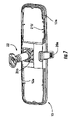
- FIG. 7 is an opposite perspective view of the reflective element assembly portion of FIG. 6 ;
- FIG. 8 is a perspective view of a cap portion of the mirror assembly of FIG. 5 ;
- FIG. 9 is a perspective view of a cap portion and circuit boards of FIG. 5 , as assembled.
- FIG. 10 is a rear perspective view of another interior rearview mirror assembly of the present invention.
- FIG. 11 is a rear elevation of another interior rearview mirror assembly of the present invention.
- FIG. 12 is a front elevation of an interior rearview mirror assembly, having directional heading or compass display in accordance with the present invention.
- FIGS. 13A-D are enlarged elevations of customized compass displays in accordance with the present invention.
- FIG. 14 is a front elevation of another interior rearview mirror assembly, showing another compass display in accordance with the present invention.
- FIG. 15 is a front elevation of another interior rearview mirror assembly, showing another compass display in accordance with the present invention.
- FIG. 16 is a front elevation of another interior rearview mirror assembly, showing another compass display in accordance with the present invention
- FIG. 17 is a front elevation of another interior rearview mirror assembly having a compass and temperature display
- FIG. 18 is a front elevation of another interior rearview mirror assembly, having a garage door opening system display and user inputs in accordance with the present invention.
- FIG. 19 is a front elevation of another interior rearview mirror assembly, having a compass display and a tire pressure monitoring system display in accordance with the present invention.
- FIG. 20 is a front elevation of another interior rearview mirror assembly, having a tire pressure monitoring system display in accordance with the present invention.
- FIG. 21 is an enlarged front elevation of another tire pressure monitoring system display in accordance with the present invention.
- FIG. 22 is a front elevation of another interior rearview mirror assembly, having a telematics module and display in accordance with the present invention.
- FIG. 23 is a front elevation of another interior rearview mirror assembly, having a telematics module and display in accordance with the present invention.
- FIG. 24 is a perspective view of a cap portion for an interior rearview mirror assembly in accordance with the present invention.
- FIG. 25 is an enlarged perspective view of a light actuator of the cap portion of FIG. 24 ;
- FIG. 26 is a perspective view of another cap portion of the present invention.
- FIG. 27 is an upper perspective view of an interior rearview mirror assembly of the present invention, with microphones positioned along an upper cap portion;
- FIG. 28 is a sectional view of an interior rearview mirror assembly having a battery in accordance with the present invention.
- FIG. 29 is an exploded perspective view of another interior rearview mirror assembly in accordance with the present invention.
- FIG. 30 is a rear perspective view of the mounting assembly of the mirror assembly of FIG. 29 ;
- FIG. 31 is a sectional view of the mounting arm and mount of FIG. 30 ;
- FIG. 32 is a rear perspective view of another mounting assembly of the present invention.
- FIG. 33A is a sectional view of an electrochromic reflective element assembly portion in accordance with the present invention.
- FIG. 33B is a sectional view of another electrochromic reflective element assembly portion in accordance with the present invention.
- FIG. 34 is a perspective view of another interior rearview mirror assembly and a windshield accessory module in accordance with the present invention.
- FIGS. 35A-D are perspective views of different accessory modules of the present invention.
- an interior rearview mirror assembly or modular prismatic rearview mirror assembly 10 for a vehicle includes a reflective element assembly portion 13 including a mirror holder 12 and a reflective element 14 ( FIG. 1 ) positioned at and at least partially within the mirror holder and/or bezel portion, that preferably is molded from a polyolefin material, such as a polypropylene material or the like.
- Mirror assembly 10 includes a plastic molded cap or cap portion 16 , preferably molded from an ABS material, an engineering resin material, such as a filled or unfilled nylon material, or the like (and may be integrally molded with metallic or ceramic materials or inserts or the like to provide mechanical bracing and enhanced structural rigidity).
- Cap portion 16 is mountable or attachable to a rear portion or open portion 12 a of mirror holder 12 , and may include an accessory or feature or the like, such as a printed circuit board 18 having an electronic accessory or circuitry thereon or integrated therein or attached thereto. Cap portion 16 may be snapped or otherwise mounted to or attached to the open rear portion 12 a of mirror holder 12 to install or back-load the printed circuit board and/or accessory within the mirror holder 12 of mirror assembly 10 . Cap portion 16 may be detachably mounted or attached to the mirror holder, such as via accessible detents or snaps or the like, and may be removable or detachable from the rear portion of the mirror holder, such as for service or replacement of the cap portion or one or more accessories of the cap portion.
- an accessory or feature or the like such as a printed circuit board 18 having an electronic accessory or circuitry thereon or integrated therein or attached thereto.
- Cap portion 16 may be snapped or otherwise mounted to or attached to the open rear portion 12 a of mirror holder 12 to install or back
- Various cap portions of the present invention may be provided with different options or accessories, and may be selected to mount to or attach to a universal or common mirror holder to form different mirror assemblies having different content.
- the present invention thus allows an automobile manufacturer to order or purchase common or standard mirror holders or reflective element assembly portions and different or custom cap portions and to assemble the mirror assembly with the desired cap portion and content at the vehicle assembly plant.
- the automobile manufacturer may even choose to purchase the mirror holders (which may include the reflective element) from one source and the cap portions from another source, and may complete the mirror assembly at the vehicle assembly plant or at another facility, such as a mirror assembly plant or the like.
- the present invention thus allows an automobile manufacturer to order or purchase the mirror holder and reflective element (and maybe the toggle assembly and mounting assembly as well, such as shown in FIGS. 6 and 7 ) from a mirror specialist, and the cap portions and accessories (such as shown in FIG. 9 ) from an electronics specialist.
- the cap portion may snap or otherwise attach to the mirror holder to complete the assembly of the rearview mirror assembly.
- the cap portion or portions may be purchased separately, the present invention lends itself to aftermarket applications or to dealership or consumer customizations/personalizations, where a cap portion having the desired accessories or appearance or design may be purchased and installed to a mirror holder to alter or upgrade the mirror assembly of the vehicle. It is envisioned that such an upgrade could be made to a base mirror that does not originally include any electronic accessories, whereby the cap portion could provide electrical content to the mirror assembly.
- the cap portion may connect to a power source or the like of the vehicle (such as via a wire or cable that extends between the mirror assembly and the headliner or an accessory module of the vehicle when the mirror assembly is installed in the vehicle) or the cap portion may include a battery or self-contained power source to provide power to the accessories and circuitry contained within the cap portion, such as discussed below with respect to FIG. 28 .
- cap portions may be provided as aftermarket cap portions, and a consumer may purchase a desired cap portion, which may have desired content or features and/or may have a desired color or texture or appearance or the like, and may readily remove the existing cap portion from the mirror of their vehicle and replace it with the new cap portion.
- the cap portion and/or the mirror holder may have snaps or clasps that may retain the cap portion and the mirror holder together, but that may release or detach such that the cap portion may be detachable from the mirror holder by a user.
- the cap portion may be pulled or detached from the mirror holder and a new cap portion may be pressed or snapped into place on the mirror holder to provide the vehicle owner with the new cap portion having the desired content or functions or features and/or the desired appearance or the like, as discussed in detail below.
- Reflective element 14 may comprise a prismatic reflective element having a wedge shaped prism with a reflective coating on its rear surface, such as described in U.S. Pat. Nos. 6,318,870; 5,327,288; 4,948,242; 4,826,289; 4,436,371; and 4,435,042; and/or U.S. patent application Ser. No. 10/709,434, filed May 5, 2004 by Lynam for MIRROR REFLECTIVE ELEMENT; and/or U.S. provisional application Ser. No. 60/525,952, filed Nov. 26, 2003 by Lynam for MIRROR REFLECTIVE ELEMENT FOR A VEHICLE, which are all hereby incorporated herein by reference.
- Reflective element 14 may include one or more displays which may be laser-etched or otherwise formed thereon, such as via an appliqué or the like on the surface of the reflective element or such as a display on demand type of display (discussed below).
- the display may include one or more display elements, such as illumination sources, such as vacuum fluorescent (VF) elements, liquid crystal displays (LCDs), light emitting diodes (LEDs), such as inorganic LEDs or organic light emitting diodes (OLEDs), electroluminescent (EL) elements or the like.
- the prismatic reflective element may comprise a display on demand or transflective prismatic element (such as described in PCT Application No. PCT/US03/29776, filed Sep. 19, 2003 by Donnelly Corp. et al.
- prismatic reflective element 14 may include a compass display 14 a and/or other display, such as a passenger side inflatable restraint status display 14 b ( FIGS. 2-4 ) or the like, formed or etched on the reflective element.
- the compass display 14 a may include ports 15 a , such as icons, characters or directional headings (N, S, E, W), etched or formed in the reflective coating of the reflective element (such as via removing the reflective coating of the reflective element to form a desired port or icon or character and/or such as by utilizing aspects described in U.S. Pat. No.
- the reflective element 14 may include an anti-scatter film or sheet or tape 14 c applied over its rear surface.
- the tape 14 c may be adhered or otherwise attached to the rear surface of the reflective element so as to limit shattering or scattering of the mirror glass if the vehicle is involved in an accident.
- the reflective element 14 may include a display appliqué 14 d that may be adhered or applied to the rear surface of the reflective element in the general region of the display 14 a (and/or at the region of other displays at the reflective element).
- the display appliqué 14 d may comprise a diffusing element or material, such as a white diffusing material with a smoked front or the like, to diffuse the light emitted by the display elements so that a person viewing the display 14 a will not readily discern the individual lighting elements or filaments, but will view substantially uniform illumination provided by the lighting elements or filaments.
- a diffusing element or material such as a white diffusing material with a smoked front or the like
- Interior rearview mirror assembly 10 may include a toggle assembly 20 and a mounting portion 22 , which may be pivotally connected to toggle assembly 20 and mounted to the vehicle to provide pivotal movement of the mirror holder and reflective element relative to the vehicle.
- Toggle assembly 20 may include a toggle member 20 a , which may be actuated or moved by a user to adjust the mirror holder and reflective element relative to the vehicle.
- toggle member 20 a may comprise a soft touch surface or portion, such as disclosed in U.S. Pat. Nos. 6,318,870 and 6,349,450, which are hereby incorporated herein by reference.
- Such a soft touch surface or portion preferably comprises a soft touch material (such as a thermoplastic elastomer or other similar thermoplastic materials, such as Santoprene or the like), preferably having a Shore A durometer value of less than about 110 Shore A, more preferably less than about 90 Shore A, and most preferably less than about 70 Shore A, that may be molded over a rigid or harder material or structure, such as by utilizing aspects described in U.S. Pat. No. 6,349,450, which is hereby incorporated herein by reference.
- a soft touch material such as a thermoplastic elastomer or other similar thermoplastic materials, such as Santoprene or the like
- the toggle assembly or the mirror holder may also include a pivot joint or pivot element 20 b , such as a socket and/or ball member, molded or formed thereon or attached or mounted thereto, in order to provide pivotal movement or adjustment of the mirror assembly relative to the mounting arm or portion.
- the mounting portion 22 may be mounted to the vehicle, such as to an interior surface of the vehicle windshield or to a header portion of the vehicle or the like, via any mounting arm and button or any other mounting arrangement or construction, such as the types disclosed in U.S. Pat. Nos.
- the mirror assembly may be mounted to the vehicle portion (such as to the windshield or headliner of the vehicle) via a substantially plastic or all plastic double ball mounting arrangement, such as described in U.S. Pat. No. 6,318,870 and/or U.S. patent application Ser. No. 10/032,401, filed Dec. 20, 2001 by March et al. for INTERIOR REARVIEW MIRROR ASSEMBLY WITH POLYMERIC COMPONENTS, now U.S. Pat. No. 6,877,709, which are hereby incorporated herein by reference.
- the mounting arrangement may be configured to provide for wiring to the mirror assembly through the mounting arrangement and to or into the mirror assembly, without affecting the scope of the present invention.
- the mounting member or arm may be inserted into the socket portion at the reflective element assembly portion (such as at the reflective element or at a backing plate of the reflective element or at a toggle assembly of the mirror assembly or the like) via an automated device or machine or by a robot.
- the automatic device or machine may be used to attach or snap the front end of the mounting member to the socket portion at the reflective element.
- the mirror assembly may provide or include an automatic flip prismatic reflective element, such as described in U.S. Pat. Nos. 6,717,712; 6,568,414; and/or 6,382,806, which are hereby incorporated herein by reference.
- an automatic flip prismatic reflective element such as described in U.S. Pat. Nos. 6,717,712; 6,568,414; and/or 6,382,806, which are hereby incorporated herein by reference.
- the circuit board and any display elements positioned thereon is/are generally fixedly secured to the cap portion, which in turn is generally fixedly secured to or relative to the mirror holder and reflective element, the circuit board and display elements move with the reflective element during adjustment of the mirror, such that there is substantially no change in the juxtapositioning/alignment of the lighting or display through the prismatic reflective element.
- Mirror holder 12 of interior rearview mirror assembly 10 preferably comprises a unitary or one-piece mirror holder (preferably molded from a thermoplastic resin, such as a polyolefin, such as polypropylene or the like), which may be molded or otherwise formed with a bezel portion 12 b integrally formed therewith, and which receives the prismatic reflective element therein.
- a thermoplastic resin such as a polyolefin, such as polypropylene or the like
- the toggle assembly 20 and mounting portion 22 may be attached to the mirror holder/bezel portion 12 , preferably while the mirror holder is still warm and pliable.
- the reflective element 14 may be attached to or inserted into the mirror holder/bezel portion 12 at around the same time to form a mirror holder assembly that may be attached to the appropriate or desired cap portion, as discussed below.
- the reflective element and molded portion or bezel portion thus may define a reflective element assembly portion 13 of the mirror assembly 10 .
- the toggle assembly 20 and the prismatic reflective element 14 thus may be secured into place (such as by snapping together) at or in the mirror holder 12 while the molded mirror holder (preferably the freshly molded mirror holder) is still warm and pliable, such as disclosed in U.S. Pat. No. 4,436,371, issued to Wood et al., which is hereby incorporated herein by reference.
- the molded mirror holder (preferably the freshly molded mirror holder and thus just exiting the injection molding press, or alternately, and less desirably, a heated mirror holder having been heated, such as in an oven or the like, to make the mirror holder warm and pliable) cools and shrinks, the mirror holder grips around the toggle assembly and the prismatic reflective element to retain the toggle assembly and the reflective element in the reflective element assembly portion.
- the material of the mirror holder or bezel portion, and/or of the reflective element assembly portion in totality may be selected to have a desired linear mold shrinkage or tool shrinkage factor to provide the desired amount or degree of shrinkage as the mirror holder cools and shrinks around the reflective element to secure the reflective element at the mirror holder or bezel portion.
- at least the bezel material, and preferably the reflective element assembly portion in totality may have a linear mold shrinkage or tool shrinkage factor of preferably at least about 0.01 cm/cm or about 1%, and more preferably at least about 0.015 cm/cm or about 1.5%.
- a UV stabilized, general purpose black polypropylene polymeric molding resinous material such as is commercially available from Huntsman Corp.
- the bezel portion may be a suitable material for the bezel portion in that it provides a desired degree of shrinkage around the reflective element as the material cools, and after formation of the mirror holder or bezel portion by molding in an injection molding operation and/or after heating an already-molded mirror holder or bezel portion to an elevated temperature (such as greater than 70 degrees Celsius or higher), in order to sufficiently retain the reflective element at the bezel portion.
- test standards such as by test standards set by the American Society for Testing and Materials (ASTM), such as the ASTM D 955 (Standard Test Method of Measuring Shrinkage from Mold Dimensions of Thermoplastics), which is hereby incorporated herein by reference, or such as by ISO 294-4, which is hereby incorporated herein by reference.
- ASTM D 955 Standard Test Method of Measuring Shrinkage from Mold Dimensions of Thermoplastics
- ISO 294-4 which is hereby incorporated herein by reference.
- the rear portion 12 a of mirror holder 12 may have openings or apertures 12 c formed therethrough at either or both sides of the toggle assembly to allow for insertion of the accessory or accessories supported by the corresponding cap portions, as discussed below.
- the mirror holder 12 ′ may be substantially open for a unitary cap portion 16 ′′ to attach at, as also discussed below.
- the cap portion 16 may be attached or secured to the rear portion 12 a of mirror holder 12 to complete the assembly of rearview mirror assembly 10 .
- the material selected for the cap portion need not have such shrinkage properties as described above, because the cap portion may be fabricated at and supplied from separate operations, locations and/or facilities than the bezel portion.
- the cap portion may be fabricated at the same facility or location, but could by made during a different operation and/or at a different time, without affecting the scope of the present invention.
- the cap portion preferably is formed by injection molding of a polymeric resinous material having a tool shrinkage factor of less than and preferably substantially less than about 0.01 cm/cm or about 1% (although it may also have higher tool shrinkage factors, without affecting the scope of the present invention), and preferably less than approximately 0.008 cm/cm or about 0.8%. This enables the provision in the cap portion of material properties not readily deliverable by the higher linear mold shrinkage or tool shrinkage factor materials used for the bezel portion.
- the cap portion material may have a higher heat stability/higher heat deflection property/higher flexural modulus compared to the reflective element assembly portion, in order to maintain any accessories or elements mechanically attached thereto or therein.
- the cap portion material may be selected to provide a higher structural strength if desired.
- the cap portion material may comprise a high temperature ABS material, such as available from BASF or others under the trade name TERLURAN® GRADE-HH106, which has a tool shrinkage factor of around 0.006 cm/cm or 0.6%, or other suitable materials, such as Nylon and preferably a filled Nylon material or the like. Such a material may also provide structural characteristics that are suitable for supporting accessories or the like.
- the cap portion material may desirably have a heat deflection temperature under load of 0.45 MPa of greater than approximately 100 degrees Celsius (and more desirably, greater than approximately 110 degrees Celsius and most desirably greater than approximately 115 degrees Celsius), as determined by standard testing, such as by ASTM 648 or ISO 75-1/-2 (which are hereby incorporated herein by reference) or the like. Such testing may determine the temperature at which an arbitrary deformation occurs when a specimen of the material is subjected to an arbitrary set of testing conditions or parameters.
- the tool shrinkage factor of the resinous material molded to form the cap portion thus is preferably less than the tool shrinkage factor of the resinous material molded to form the bezel portion of the reflective element assembly portion.
- the flexural modulus of the material that forms the cap portion may preferably be greater than the flexural modulus of the material that forms the mirror holder or bezel portion.
- the material that forms the cap portion may preferably have a higher heat deflection temperature (such as may be determined by standard testing, such as ASTM D-790, which is hereby incorporated herein by reference) than the material that forms the bezel portion or mirror holder.
- Such standardized testing may determine the flexural properties or flexural strength of the material via bending or breaking of specimens of the material in accordance with the appropriate test parameters.
- the polymeric resinous materials used for the bezel portion and the cap portion may be different, the portions may have similar exterior finishes and/or textures. Alternatively, however, the portions may have different finishes and/or textures or the like as discussed below, without affecting the scope of the present invention.
- the mirror holder and reflective element assembly portion may be packaged and moved to another facility and/or the cap portion may be received from another facility to complete the mirror assembly.
- the appropriate or selected cap portion (with the appropriate associated electrical circuitry/accessory/content) may then be attached to the reflective element/mirror holder assembly, such as at the vehicle assembly line, to assemble the mirror assembly for installation into the appropriate vehicle having the optional content of the mirror assembly, as discussed below.
- the modular mirror assembly of the present invention thus facilitates assembly of the reflective element assembly portion and of the cap portion at different assembly locations, whereby the two portions may be joined or assembled together at a different location, such as at the vehicle assembly plant, to complete the mirror assembly.
- the cap portion may attach to the reflective element assembly portion via a snap together connection or other type of connection, and may removably or detachably attach, so that the cap portion may be removed from the reflective element assembly portion if desired.
- the cap portion may alternatively be non-detachably attached, such as by adhesive attachment or by heat staking or by ultrasonic welding or the like, without affecting the scope of the present invention.
- the cap portion may attach to the reflective element assembly portion via any manner, such as, for example, utilizing aspects described in U.S. Pat. No. 6,402,331, which is hereby incorporated herein by reference.
- the present invention encompasses customization/selection of material properties for the cap portion to be different from material properties selected for the reflective element assembly portion so that decorative finishes and/or functional properties may be customized/delivered to be the same or different for one or both of the portions.
- one or more accessory modules or blocks may be attached to or inserted or plugged into the cap portion and/or mirror assembly, such as at the vehicle assembly line, to provide a desired or selected or customized optional feature or accessory to the mirror assembly.
- the accessory module may insert or attach to the mirror assembly or cap portion utilizing aspects described in U.S. Pat. Nos. 6,672,744; 6,402,331; 6,386,742; and 6,124,886, and/or U.S. patent application Ser. No. 10/739,766, filed Dec. 18, 2003 by DeLine et al. for MODULAR REARVIEW MIRROR ASSEMBLY, now U.S. Pat. No. 6,877,888, which are hereby incorporated herein by reference.
- the accessory module may include circuitry and display elements and user inputs, and may plug into the cap portion or mirror assembly in a manner whereby mechanical and electrical connections are preferably simultaneously made as the module is inserted into the cap portion or mirror assembly, such as by utilizing aspects described in U.S. Pat. No. 6,669,267, and/or U.S. patent application Ser. No. 10/727,731, filed Dec. 3, 2003 by Lynam et al. for EXTERIOR ACCESSORY MODULE FOR VEHICULAR MODULAR DOOR, now U.S. Pat. No. 6,969,101, which are hereby incorporated herein by reference.
- the mirror assemblies thus may be customized to particular work orders or selected options at the vehicle assembly line via insertion or attachment of the appropriate accessory module, such that the cap portion and the reflective element assembly portion may comprises common or universal components for two or more options offered for the particular mirror assembly or vehicle application.
- the modular mirror assembly of the present invention thus may provide fully assembled mirror assemblies to a vehicle assembly plant and line, where the cap portion and selected content are attached to the reflective element assembly portion at a remote location, such that different mirror assemblies are provided for different options or applications.
- the modular mirror assembly may provide a universal or common reflective element assembly portion to a vehicle assembly plant, and a selected cap portion (with the appropriate or desired or selected optional content) may be attached to the reflective element assembly portion at the vehicle assembly line to customize the mirror assembly for the particular selected option or application.
- the modular mirror assembly of the present invention may provide a universal reflective element assembly portion and a partially or substantially universal (at least universal as to two or more selectable options) cap portion, whereby the selected accessory module may be inserted into or attached to the cap portion and/or mirror assembly at the vehicle assembly line to complete the mirror assembly and to provide the desired or selected option or feature to the mirror assembly.
- cap portion 16 may comprise two separate cap portions 16 a , 16 b , or a cap portion 16 ′ ( FIG. 3 ) may have two cap portions 16 a ′, 16 b ′ joined together by a connecting portion or wire channel 16 c .
- One or both of the cap portions 16 a , 16 b may have an accessory or circuit board 18 a , 18 b attached thereto.
- the circuit board or boards may snap or otherwise affix or secure to the cap portion or portions.
- the cap portions may have retainers or pillars extending from an interior surface for retaining and supporting the circuit board or boards thereon.
- the cap portion may comprise a unitary cap portion 16 ′′ ( FIGS.
- the cap portion may receive the mounting portion 22 between the side portions of the cap portion 16 ′ ( FIG. 3 ) or through an opening 25 a in the cap portion 16 ′′ ( FIGS. 4 , 8 - 11 , 24 and 26 ) as the cap portion is attached to the mirror holder.
- the mounting portion 22 may be threaded through the opening 25 a in the cap portion as the cap portion is moved toward and into engagement with the bezel portion during the mirror assembly process.
- the mirror assemblies 10 ′ and 10 ′′ may be substantially similar to and may have substantially similar components and accessories as mirror assembly 10 (with cap portions 16 a , 16 b ), such that a detailed description will not be repeated for the different mirror assemblies.
- the common or similar components of the mirror assemblies are referred to in FIGS. 2-11 with the same reference numbers.
- the cap portion 16 or portions 16 a , 16 b may be positioned at openings 12 c of mirror holder 12 such that the accessories or circuitry supported by the cap portions are positioned generally within mirror holder 12 .
- the cap portions may snap onto the rear portion 12 a of mirror holder 12 and generally cover the openings 12 c in mirror holder 12 .
- the unitary cap portion 16 ′′ may snap onto or otherwise secure to the mirror holder and generally cover or define the rear portion of the mirror assembly when so assembled. The cap portion or portions thus support the circuit board or circuit boards and associated circuitry and/or accessories at or within the mirror assembly.
- the circuit boards or accessories may be provided at, within or on the cap portions at a cap portion manufacturing facility or electrical accessory manufacturing facility, such that the cap portion and circuitry assemblies are provided as a unit to the mirror assembly facility or plant.
- the cap portion and circuitry units may then be snapped or otherwise affixed to the mirror holder or reflective element assembly portion of an appropriate mirror assembly having features or components or displays corresponding to the cap portion and circuitry units, as discussed below.
- the assembly or back-loading of the cap portions to the mirror holder and reflective element assembly portion thus may be performed remote from the molding tool for molding the mirror holder, since the cap portions may be mounted to the mirror holder after the mirror holder has cooled and shrunk.
- Each cap portion may support one or more desired accessories or circuit boards for providing the desired feature to the mirror assembly.
- the cap portions, and corresponding accessory or feature or electrical content may be selected and attached to a universal or common mirror holder to provide different features to the mirror depending on the options selected for a particular application or vehicle.
- the cap portions may be selected/configured to have accessories contained/supported therein to correspond to and be aligned with/juxtapositioned with one or more displays of a particular or respective reflective element secured in the common mirror holder and/or may correspond with a particular mirror holder for applications where the accessory includes buttons or controls which may extend through openings or recesses in the mirror holder for access thereto by the driver or occupant of the vehicle, as discussed in detail below.
- the cap portion or cap portions may be snapped or otherwise secured to the rear portion 12 a of mirror holder 12 , such as generally at and covering corresponding openings 12 c through the rear portion 12 a of mirror holder 12 .
- the opening or openings 12 c may be at either or both sides of the toggle assembly and mounting portion of the mirror assembly.
- the cap portion may snap over or otherwise interconnect with the respective opening via a plurality of hooks or snap clasps (which may extend from the cap portion or the mirror holder) engaging a plurality of corresponding slots or the like at the other of the cap portion and the mirror holder.
- the cap portion may be formed to provide an exterior surface which may substantially match the exterior surface of the mirror holder to provide a finished appearance to the mirror assembly when the cap portions are attached to the mirror holder and thus form the rear or back portion of the mirror holder and/or it may provide a contrast or distinctive aesthetic or functional appearance or finish.
- the mirror holder and the cap portions may be formed of a polypropylene material or a talc-filled polypropylene material or the like, or preferably the mirror holder is formed of a molded polyolefin, while the cap portion is formed of a molded engineering resin, such as ABS or a Nylon or the like.
- the cap portion may comprise a metallic material or may comprise a polymeric molding overcoated with a metallic layer or coating, and may have ribs or ripples to provide enhanced rigidity of the cap portion, without affecting the scope of the present invention.
- the cap portion may have a different color or texture (such as a chrome or colored or textured surface or the like) than the mirror holder or bezel portion to provide a two-tone configuration to the mirror assembly.
- the cap portion and/or the mirror holder may have a decorative finish, and may be painted or plated, such as electroplated or the like, or may have a film or an in mold film or coating thereon to provide the desired surface to the cap portion and/or the mirror holder.
- the cap portion (or the mirror holder) may provide a contrast or accent color or may be chrome plated or may be brushed aluminum or the like or may provide an angle variant color (where the perceived color may change depending on the viewing angle) or may provide various colors or patterns or textures or the like as may be desired by a consumer (for example, certain colors or patterns or textures may be provided to target different demographics, such as for targeting teenagers or other age groups or genders or the like).
- the cap portion or bezel portion may have a fabric cover (such as, for example, leather or cloth or denim or other cover material or the like) at and substantially over at least a portion or the entirety of its exterior surface to provide a desired appearance or texture or the like.
- the cap portion and/or the mirror holder or bezel portion may have a soft touch surface, such as a soft touch surface and material similar to that described above (preferably having a Shore A durometer value of less than about 110 Shore A, more preferably less than about 90 Shore A, and most preferably less than about 70 Shore A) with respect to the toggle tab and/or similar to the types described in U.S. Pat. Nos. 6,318,870 and/or 6,349,450, which are hereby incorporated herein by reference.
- either the mirror holder or the cap portion may have such a soft touch surface independent of the other, or both may have such a soft touch surface or neither may have a soft touch surface.
- the cap portion may be finished with a metallized reflective finish, such as a chrome or chrome-plated finish
- the bezel portion desirably may not be chrome or chrome-plated or the like, in order to reduce reflections or glare at the bezel portion around the reflective element, and thus not be specularly reflecting.
- the cap portion or bezel of the interior or exterior mirror assembly may include a personalization element, such as a logo or text or pattern or other indicia, thereon as desired by the consumer to provide highly personalized and unique mirror assemblies for the particular consumers that purchase the vehicles or the mirror assemblies, such as described in U.S. provisional applications, Ser. No. 60/553,842, filed Mar. 17, 2004 by Bareman et al. for METHOD OF MANUFACTURING ELECTRO-OPTIC MIRROR CELL; and Ser. No. 60/563,342, filed Apr. 19, 2004 by Bareman et al. for METHOD OF MANUFACTURING ELECTRO-OPTIC MIRROR CELL, which are hereby incorporated herein by reference.
- a personalization element such as a logo or text or pattern or other indicia
- the cap portion may include a school logo and colors, such as, for example, the letters “MSU” in green and white print/background, to provide a desirable appearance to the personalized mirror assembly for a particular consumer, such as, for example, a student or graduate of Michigan State University.
- the cap portion may include other text or logos or brand names or other types of identifying indicia, such as, for example, “FORD” to identify the vehicle manufacturer, or “TOMMY HILFIGER” to identify the vehicle owner's clothing preference or the like, or other text or messages or images or trademarks or colors or patterns or indicia or the like to provide a desired appearance or identification or message or statement or advertisement or logo or sponsorship identification or style or brand identification on the interior or exterior mirror assembly.
- the mirror assemblies may thus be assembled to have the desired or personalized cap portion with the desired or personalized logo or color or message or indicia thereon to provide the desired or personalized finish or appearance of the interior or exterior mirror assembly.
- cap portions as described above may be provided as aftermarket interior or exterior mirror cap portions.
- a consumer may then purchase a desired cap portion, which may have desired content or features and/or may have a desired color or texture or appearance or the like, and may readily remove the existing cap portion from the interior or exterior mirror assembly of their vehicle and replace it with the new cap portion.
- the cap portion and/or the mirror holder or reflective element assembly portion (such as the mirror support arm for an interior rearview mirror assembly or a mirror mount for an exterior rearview mirror assembly) may have snaps or clasps that may retain the cap portion and mirror holder/mount/bezel together, but that may release or detach such that the cap portion may be detachable from the mirror assembly by a user/consumer.
- the cap portion may be pulled or detached from the mirror assembly and a new cap portion (with the desired content therein and/or personalized text or indicia or colors or the like thereon) may be pressed or snapped into place on the mirror assembly to provide the vehicle owner with the new cap portion having the desired content or functions or features and/or the desired or personalized appearance or the like.
- the modular mirror assembly of the present invention may provide customizing of other visible or viewable portions of the mirror assembly as well.
- the flip tab or toggle tab 20 a (or a rotary knob or the like depending on the type of toggle assembly of the particular mirror assembly) may be removably attached to the toggle assembly, such that the tab may be selected or replaced as desired.
- the tab may threadedly attach to a threaded stud or bolt or nut or the like at the toggle assembly (or may detachably attach via other means, such as snaps, twist-on connections, a bayonet connection or the like), such that a desired tab may be readily attached to the toggle assembly to provide the desired tab for the mirror assembly.
- the selectable or replaceable or customized toggle tabs may provide various styles, sizes, shapes, appearances, textures, touches/feels (such as a soft touch material or the like), colors, patterns, indicia (such as logos or icons or the like as described below with respect to the center port 15 c of the compass display 14 a in FIGS. 13A-D ).
- the customer/consumer thus may select the desired toggle tab for attachment to the mirror assembly (such as a tab that matches or is associated with the selected cap portion and/or bezel portion and/or reflective element ports (discussed below) or the like) to customize the mirror assembly.
- the customization and selection or replacement of the toggle tab may occur at the reflective element assembly portion assembly plant or at the mirror assembly plant or at the vehicle assembly plant or at the vehicle dealership or at any other aftermarket facility or the like, without affecting the scope of the present invention.
- the custom tab may thus be selected and attached or replaced at the mirror assembly to provide a custom appearance without having to retool or mold a different toggle assembly.
- the bezel portion 12 may be molded of a universal or standard color, finish and/or material, such as a black plastic material or black polypropylene or the like, and an outer rim portion or perimeter trim portion element may attach to a forward edge of the bezel portion (at the viewable side of the reflective element) to provide a desired appearance and/or functionality of the bezel portion of the mirror assembly to the driver and passenger of the vehicle.
- the bezel portion 12 may be formed to have a recess or trough or lip or the like around its perimeter portion (such as at 12 b in FIG.
- the attachable trim portion element may provide various styles, appearances, textures, touches/feels (such as a rubber or elastomeric material or soft touch material or the like), colors, patterns, indicia (such as logos, icons or the like as described below with respect to the center port 15 c of the compass display 14 a in FIGS. 13A-D ).
- the customer thus may select the desired trim portion element for attachment to the bezel portion of the mirror assembly (such as a trim portion element that matches or is associated with the selected cap portion and/or toggle tab and/or reflective element ports (discussed below) or the like) to customize the mirror assembly.
- the trim portion element may be selected to provide a soft material or an impact absorbing material, and may have a Shore A durometer hardness that is less than that of the bezel portion or mirror holder.
- the customization and selection or replacement of the trim portion element may occur at the reflective element assembly portion assembly plant or at the mirror assembly plant or at the vehicle assembly plant or at the vehicle dealership or at any other aftermarket facility or the like, without affecting the scope of the present invention.
- the bezel portion thus may be formed as a universal or common bezel portion, and the viewable rim of the bezel portion (such as around the perimeter of the reflective element and viewable by a driver of the vehicle when the mirror is installed in the vehicle) may be selected or replaced to provide the desired or customized appearance and/or feel of the mirror assembly.
- the cap portion, or one of the cap portions, such as the cap portion 16 b on the side of the mirror assembly, such as the side which will be toward the passenger side of the vehicle when the mirror assembly is installed in the vehicle may include an electrical connector for connecting the accessory or circuit board or boards 18 a , 18 b to a vehicle wiring harness or power source of the vehicle.
- the circuit board 18 b at the cap portion may include a multi-pin connector 24 for connecting to a corresponding multi-pin connector of the vehicle wire harness.
- an opening (such as opening 25 b of cap portion 16 ′′ in FIGS.
- the circuit board 18 b or connector 24 may be substantially supported at the cap portion to provide sufficient support of the connector when a corresponding connector of the wire harness is pushed into engagement with connector 24 .
- the cap portion or mirror holder may have a connector formed therein, whereby the wire harness may then connect to or plug into the connector at the rear of the mirror assembly.
- the connector may be formed as a selected or appropriate connector (such as a six pin or eight pin connector or the like) depending on the accessories of the cap portions.
- the connector may be formed with an insert in the mold or tool for forming the cap portion, such that an appropriate insert may be placed in the mold or tool to form the desired or appropriate connector on that particular cap portion. In the illustrated embodiment of FIGS.
- the connector 24 of the circuit board includes a plurality of pins 24 a for connecting to a connector or plug
- the cap portion 16 ′′ has an opening 25 b formed therethrough so that the connector or plug may readily connect to the circuit board, and may snap or otherwise be fastened or secured thereto, such as via clasps or the like at the plug and/or at the cap portion 16 ′′.
- the circuit board 18 a on the cap portion 16 a (or the circuit board on one side of the unitary cap portion) opposite the connector 24 may be connected to the other circuit board 18 b and/or connector 24 via one or more connecting wires 26 , in order to provide power and/or control to the accessory on cap portion 16 a .
- the connecting wire or wires 26 may extend between the cap portions 16 a , 16 b within the mirror holder 12 or may extend along the rear surface of the mirror holder 12 , without affecting the scope of the present invention. As shown in FIG.
- cap portion 16 ′ of an interior rearview mirror assembly 10 ′ may comprise a single cap portion having a wire channel or connector 16 c extending between opposite end caps or end portions 16 a ′, 16 b ′.
- the connecting wire (not shown in FIG. 3 ) may extend between the circuit boards 18 a , 18 b or accessories supported on the end portions 16 a ′, 16 b ′ and may be routed within the wire channel 16 c or between the channel 16 c and the rear portion 12 a of the mirror holder 12 .
- a mirror assembly 10 ′′ may have the single or unitary cap portion 16 ′′ in accordance with the present invention, and a connecting wire between two circuit boards or accessories may extend along the cap portion to electrically connect the circuit boards or accessories together.
- printed circuit board 18 b may include circuitry 19 for a compass display 14 a and/or other accessory display, such as a passenger side inflatable restraint display 14 b or the like, at reflective element 12 . More particularly, circuit board 18 b may include compass display circuitry 19 having a plurality of illumination sources 19 a which are individually illuminated or illuminated in combination to project illumination through respective openings in circuit board 18 b to illuminate one or more of the ports or direction characters 15 a etched or formed in reflective element 14 , such as in the manner disclosed in U.S. patent application Ser. No. 10/456,599, filed Jun. 6, 2003 by Weller et al.
- the compass display thus may be controlled or actuated by a microcontroller or microprocessor of the cap portion of the mirror assembly.
- the controller may drive or energize the illumination sources (such as light emitting diodes or the like) directly, without the need for additional display drivers.
- the direct energization of the illumination sources of the display thus avoids the need for other controllers or drivers within the cap portion or the mirror assembly or the vehicle.
- circuit board 18 b When the cap portion 16 b (or cap portion 16 ′′ or the like) and circuit board 18 b are attached to or juxtaposed with the mirror holder 12 , circuit board 18 b may be pressed or urged toward the rear surface of reflective element 14 such that the illumination sources 19 a (such as light emitting diodes or the like) at the circuit board may generally align with the appropriate ports or characters or icons formed in the reflective element 14 , as discussed below.
- the cap portion may include guide members or posts 25 c for engaging corresponding guide members or tabs or holes or notches or recesses 18 c of the circuit board for guiding the circuit board into the appropriate position and orientation on the cap portion as the circuit board is attached or snapped to the cap portion.
- the cap portion may then attach to the mirror holder/bezel portion via engagement and guiding of corresponding tabs and holes and the like, which function to position the cap portion in the desired location relative to the bezel portion, such that the circuit board (and any illumination devices or the like positioned thereon) is/are properly aligned with any associated display ports or switches or the like at the mirror holder/bezel portion/reflective element.
- a seal or sealing member or layer 17 or the like may be applied to the rear surface of reflective element 14 or to the forward face 18 d of circuit board 18 b to substantially seal the interface between the circuit board 18 b and the reflective element 14 , in order to limit or substantially preclude light from one of the illumination sources from illuminating a port or character or icon at the reflective element other than the respective port or character or icon aligned with that illumination source and opening.
- the seal 17 may comprise an opaque material, and may comprise a white (or other color) silicone gasket or the like, to diffuse and/or reflect light.
- the seal 17 may be at least partially and preferably substantially flexible or resilient to compress and seal against the reflective element and the circuit board to limit or substantially preclude light leakage from one illumination source to one of the other ports or characters of the display.
- the circuit board may also include a connecting wire 28 which may connect to a compass pod or module 30 or other accessory or accessory module or the like for communication of compass heading or control information to the compass display circuitry 19 at the circuit board or for communication of other control information between the accessory module and the circuit board of the cap portion.
- the connecting wire 28 may extend from the cap portion and the rear of the mirror assembly to the compass module 30 , which may be attached to the mounting arm or mounting button of the mirror assembly or otherwise positioned or mounted at or near the mirror assembly.
- Compass module 30 may include the compass circuitry (which may include calibration circuitry, a microprocessor and the like) and magnetoresponsive compass sensors (such as magnetoresistive sensors, magneto-capacitive sensors, magnetoinductive sensors or the like or a flux gate sensor or the like), such as described in U.S. Pat. Nos. 6,513,252 and 5,802,727, and/or U.S. patent application Ser. No. 10/456,599, filed Jun. 6, 2003 by Weller et al. for INTERIOR REARVIEW MIRROR SYSTEM WITH COMPASS, now U.S. Pat. No. 7,004,593, which are hereby incorporated herein by reference in their entireties.
- the compass pod may also include an ambient light sensor, whereby the intensity of the compass display (and other displays of the mirror assembly) may be adjusted in response to the detected ambient light levels.
- the compass system may utilize principles disclosed in U.S. Pat. Nos. 5,924,212; 4,862,594; 4,937,945; 5,131,154; 5,255,442; and/or 5,632,092, which are hereby incorporated herein by reference.
- a compass pod or module or compass circuitry and sensors may be positioned in a post or arm of a single ball mounting arrangement such that the sensors and circuitry are generally fixedly positioned relative to the mounting button and the vehicle.
- a wire may be routed along the generally fixed mounting arm (via and through the single ball joint) and to the display elements or illumination sources, such as in a manner similar to that shown in FIG. 34 , or a wire may be routed along the mounting arm and through the single ball and into the mirror casing or a wire or conductor may be routed or positioned along the arm and ball in any other manner to communicate electrical signals and the like to the circuitry and/or illumination sources of the cap portion, without affecting the scope of the present invention.
- the wire may provide slack to allow for the adjustment and movement of the mirror holder/cap portion about the single arm to avoid pulling at the wire during adjustment of the mirror.
- the compass circuitry 19 on circuit board 18 b may also include a button or switch or control or may be in communication with a button or control 23 ( FIGS. 8 , 10 and 11 ), such as at the rear of the cap portion 16 ′′ or at the rear of the mirror holder, for actuating a calibration or zone function of the compass circuitry.
- the button 23 may include an inward protrusion 23 a ( FIGS. 8 and 24 ) that extends forwardly from the cap portion 16 ′′ or inwardly toward the button or switch or control on the circuit board when the cap portion 16 ′′ is attached to the circuit board.
- the button 23 may comprise a flexible tab 23 b integrally formed with and extending partially along the cap portion 16 ′′.
- the tab 23 b flexes and the protrusion 23 a is moved toward and urged against the button or switch on the circuit board 18 b to actuate the switch to control or activate/deactivate the associated function of the compass circuitry (or other circuitry or accessory or the like that may be associated with the switch on the circuit board).
- the compass circuitry or other circuitry or accessory or the like that may be associated with the switch on the circuit board.
- the button/flexible tab or flip actuation tab member may be integrally formed on one of the side cap portions 16 a , 16 b or end portions 16 a ′, 16 b ′ of cap portion 16 ′ or the like, or on other types of casings or housings or the like, without affecting the scope of the present invention.
- an additional illumination source or lighting element may be provided on the circuit board 18 b for projecting illumination through a corresponding port or icon or character 15 b formed on the reflective element 14 to indicate that the compass system is in the calibration mode or zone setting mode.
- the calibration mode may be indicated by a light emitting diode (LED) at the center port 15 c of the display.
- LED light emitting diode
- a dual-color LED may be provided at the center port, where illumination in one color (such as, for example, red) indicates that the compass system is in the calibration mode.
- illumination may be provided in the other color (such as, for example, blue).
- the other color (such as blue) indication color may be provided.
- the calibration mode could be indicated without a dedicated illumination source or light emitting diode or the like (because such an indicator would be used very rarely in the life of the part).
- the center illumination source or LED which may be activated to provide an anchor point or focal point for the display, as discussed below
- the center illumination source or LED may be flashed or otherwise modulated or adjusted when the system is in the calibration mode, or other similar types of indication may be provided to convey to the driver that the compass is in its calibration mode.
- the circuit board 18 b may also have an ambient light sensor or photocell (not shown) for detecting the ambient light level at the mirror assembly, whereby the circuitry may adjust the intensity of the display in response to the detected ambient light levels.
- a corresponding opening in the mirror holder 12 or at the rear of the cap portion 16 may allow the ambient light sensor to detect the ambient light levels through the opening.
- the light sensor may alternately be positioned at the compass pod or module 30 , without affecting the scope of the present invention.
- the compass display 14 a ( FIGS. 1-5 and 12 ) thus may include a plurality of direction indicating ports 15 a (such as four such ports formed to represent the cardinal directional points or “N”, “E”, “S” and “W” or the like) and may include an additional port 15 b for a calibration indicator or light source, such as described in U.S. patent application Ser. No. 10/456,599, filed Jun. 6, 2003 by Weller et al. for INTERIOR REARVIEW MIRROR SYSTEM WITH COMPASS, now U.S. Pat. No. 7,004,593, which is hereby incorporated herein by reference in its entirety.
- Compass display 14 a may further include a center port 15 c etched or otherwise formed at a central region of the display 14 a .
- Center port 15 c may provide an opening or port for a rearward facing photosensor positioned at the circuit board to receive light therethrough to determine the ambient light at or in the vehicle cabin (or a glare sensor for determining glare at the mirror assembly for controlling an exterior electrochromic mirror assembly or cell or the like as discussed below) when the mirror assembly is assembled and positioned in the vehicle, such as discussed below.
- center port 15 c may align with an illumination source or light emitting diode at the circuit board to provide a visible center indicator or central anchor or focal point at the central region of the display 14 a such that a person may readily identify the center of the compass display.
- the indicator or light source at center port 15 c may also be energized to provide a visible central anchor point for a person to recognize as the central region of the display.
- an extra illumination source or port that is central to the rosette N-E-S-W indicia thus helps to serve as a reference point for the driver, in order to aid the driver's cognitive association of the cardinal direction point that is intended to be communicated when any one (or combination of two) of the N, E, S, W icons or ports are illuminated.
- the light emitting diodes aligned with the directional indicating ports 15 a may be one color, while the light emitting diodes at the central port 15 c and/or at the calibration indicating port 15 b may be another color or colors.
- the directional indicating ports 15 a may be illuminated or back lit via blue indicators or light emitting diodes or the like, while the central port 15 c may be illuminated or back lit via a red or amber indicator or light emitting diode or the like, so that a person viewing the compass display in darkened conditions may readily discern which indicator is indicative of the central region of the display and thus where the center of the display is, such that the person may readily recognize which directional indicating port is illuminated, without having to look to see whether it is an “N” or an “E” or the like.
- the center port may be illuminated whenever the vehicle is on or powered, in order to provide substantially continuous illumination of the center port.
- the center port is illuminated at a lower light output intensity than that of the respective cardinal N, E, S, W ports, so as to serve as a subtle eye point, but not to be confused with an actual directional indication. For this reason, a color contrast as well as an intensity contrast may be desirable.
- an ambient sensor may be positioned elsewhere in the mirror assembly, such as elsewhere in the cap portion, and may be a forwardly facing sensor (i.e. toward the windshield when the interior rearview mirror assembly is normally mounted in the interior cabin of a vehicle) and may receive light through a port or opening 25 d in the cap portion.
- the ambient sensor may be facing downwardly or upwardly when installed in the vehicle, without affecting the scope of the present invention.
- the ambient sensor may be generally aligned with or juxtaposed at the port or opening or may receive the ambient light via a light pipe or the like, without affecting the scope of the present invention.
- the center port 15 c of the compass display 14 a may provide a graphic depiction of a desired image, such as a logo of the vehicle manufacturer or other desired image.
- the center port 15 c may be etched (such as by laser etching or ablation or by sandblasting or the like) or otherwise formed to provide the letters “FORD” or may be etched or otherwise formed in a pattern similar to the design or designs indicative of the manufacturer, such as the Chevrolet “bowtie” or the like.
- the central port 15 c is formed to be indicative of the vehicle manufacturer, such as for Dodge ( FIG. 13A ), Hyundai ( FIG. 13B ) or Jeep ( FIG. 13C ), or Subaru ( FIG. 13D ).
- the central port may be formed to be indicative of other vehicle manufacturers or entities or sponsors or indicia or trademarks or emblems or signature items, or representations of a certain political views, religious beliefs, tribal affiliations, community ties, collegiate affiliations, allegiances and/or advocacy (such as, for example, a “peace” sign or other symbol or text or the like) or other views, affiliations, beliefs, etc., or other custom ports or icons may be formed elsewhere on the reflective element to convey other information or logos or the like, without affecting the scope of the present invention.
- the desired image or logo may be indicative of the vehicle manufacturer, or may be selected by the user or vehicle owner to provide a customized interior rearview mirror assembly, such as described above with respect to the different logos or colors or textures or appearances or touch/feel provided on the cap portion or bezel portion of the mirror assembly, without affecting the scope of the present invention.
- a person may select the logo or mascot of their alma mater to be etched at the center of the compass display (or elsewhere on the reflective element) to customize the mirror assembly for that particular person or owner.
- the customized or selected port may be at the central port of the compass display or may at or incorporated into another display at the reflective element or may be elsewhere at the reflective element and separate from any other information display, without affecting the scope of the present invention.
- the light source or indicator positioned at the circuit board behind the custom port may be selected to match the color that may be typically associated with the selected logo, such as a green or red or blue indicator or light emitting diode or the like for the school color or the like.
- Other forms of customized logos or indicia or the like may be etched or otherwise formed at the reflective element, without affecting the scope of the present invention.
- an interior rearview mirror assembly 10 ′′′ may include an intuitive heading instructional icon element or display 14 a ′ at the reflective element 14 ′, such as the types described in U.S. provisional application Ser. No. 60/553,517, filed Mar. 16, 2004 by Schofield for MIRROR ASSEMBLY, which is hereby incorporated herein by reference.
- the compass display 14 a ′ may be associated with or controlled or adjusted by a compass system and/or a navigational system, such as a compass and/or navigational system of the types described in U.S. Pat. Nos.
- Display 14 a ′ includes a plurality of characters or icons or letters 15 a (such as N, E, S, W as shown in FIGS. 14-16 ) formed or etched in the reflective coating or layer of the reflective element 14 ′ and includes an arrow or direction pointer 15 d at each of the characters 15 a .
- the display 14 a ′ may also include a central port 15 c through the reflective coating or layer reflective element 14 ′ behind which may be positioned an illumination source as described above or a glare sensor, such as a photo sensor or the like, such as a glare sensor and/or an ambient light sensor and electrochromic automatic dimming circuitry described in U.S. Pat. Nos. 4,793,690 and 5,193,029, and U.S.
- the direction pointers of display 14 a ′ may comprise generally triangular shaped icons or pointers 15 d positioned outward from the characters 15 a and opposite the characters from the center or port 15 c of the display (such as shown in FIG. 14 ), or the direction pointers of the display may comprise arrows 15 d ′ positioned next to the characters 15 a (such as shown in FIG. 15 ), or the direction pointers of the display may comprise arrows 15 d ′′ positioned inward of the characters 15 a and between the respective characters and the center or port 15 c (such as shown in FIG. 16 ).
- the compass/navigation system may be operable to energize one or more illumination sources positioned at and rearward of a respective one of the characters 15 a and corresponding direction pointer 15 d to illuminate or back light the respective character and direction pointer.
- the compass/navigation system may be operable to illuminate or back light a particular character and adjacent direction pointer to indicate to an occupant of the vehicle the direction that the vehicle is currently heading. For example, if the character “W” and the arrow or direction pointer next to the “W” are illuminated, then the display indicates that the vehicle is heading west.
- the intuitive heading instructional icon element or display thus may provide reinforcement to a viewer that when the character (such as “W” or other character) is illuminated, it is done so to indicate that the vehicle is traveling in the direction (such as west or other direction) indicated by the character. This is reinforced by the illumination of the corresponding arrow or direction pointer that points upward so as to be representative of pointing in the direction of forward travel of the vehicle. A person viewing the display thus will not misinterpret the illumination of the characters to be indicative of a driving or turning instruction (such as an instruction to turn the vehicle right or east to follow a programmed route) in connection with the navigation system.
- a driving or turning instruction such as an instruction to turn the vehicle right or east to follow a programmed route
- the display may function as a display for providing both an indication of the directional heading of the vehicle and an indication of which direction the vehicle should be turned in order to follow a programmed route or path.
- a particular direction pointer may be illuminated or back lit to indicate that the vehicle is heading in the direction indicated by the non-lit character next to the illuminated pointer, while a different character (separate from the illuminated pointer) may be illuminated or back lit to indicate that the vehicle is to be turned in that direction to follow a programmed route to a desired destination.
- the compass/navigation system and display thus may clearly display to a driver of the vehicle which direction the vehicle is heading at that time via the directional arrows, while the compass/navigation system and display may also be operable to provide driving or turning instructions to a driver of the vehicle to instruct the driver as to which direction the driver is to turn to follow a particular route to a desired destination.
- the compass/navigation system may be associated with a global positioning system and/or telematics system of the vehicle, and may generate and display driving instructions to the driver of the vehicle as the vehicle is driven along a generated route, such as by utilizing aspects described in U.S. Pat. Nos. 6,678,614 and 6,477,464, and/or U.S.
- the compass/navigation system thus may be operable to energize an illumination source positioned at and rearward of/behind a respective one of the characters to provide a driving instruction to the driver of the vehicle that is separate from the directional heading indication also provided by illumination or back lighting of the arrows or pointers of the display. For example, if the vehicle is heading generally west, the compass/navigation system may illuminate or back light the arrow next to the “W” to indicate to the driver of the vehicle that the vehicle is traveling generally in that direction. If the programmed route for the vehicle involves an upcoming right turn onto a generally northbound road, the compass/navigation system may then illuminate or back light the letter “N” to indicate to the driver of the vehicle that the driver should turn the vehicle to head north.
- the illuminated character may be altered or adjusted as the vehicle gets closer to the turning point or intersection, such as by flashing the illumination source or intensifying the illumination source or changing the color of the illumination as the vehicle approaches the desired or appropriate turning point or intersection.
- arrows pointing sideways may be provided at one or more of the characters of the display (or elsewhere at the display), and the appropriate arrow may be illuminated or back lit to indicate that the driver is to turn right or left to stay on the desired course or route.
- illumination or back lighting of the character may be indicative of the directional heading of the vehicle, while illumination or back lighting of the arrows may be indicative of the driving instructions to the driver of the vehicle.
- the intuitive display elements thus provide a clear indication as to which direction the vehicle is presently traveling by providing a directional heading arrow or pointer at each of the compass heading characters.
- the driver of the vehicle thus will not likely become confused as to the meaning of the illuminated characters or letters.
- the compass/navigation system and display of the present invention also may provide point-to-point driving instructions and the present directional heading of the vehicle with the same display or display icons/characters.
- the compass display may include a temperature display or another type of information display with an LED array at or near the compass display ports or icons.
- One or more control buttons or inputs may be provided to allow the driver or occupant of the vehicle to select or actuate the calibration or zone or temperature display functions.
- the circuit board may be in communication with a temperature sensor or system, such as via a connecting wire or the like, to receive an electronic signal indicative of the temperature to be displayed.
- the cap portions and circuit boards may support or provide a compass and/or temperature display utilizing vacuum fluorescent displays and filters to display the compass heading and/or temperature via two or more characters or letters or numbers. For example, and as shown in FIG.
- a compass heading display 32 a and a temperature display 32 b may be provided or formed at a display region 32 c of a reflective element 14 ′′ of a mirror assembly.
- the displays may comprise alphanumeric characters or the like to convey the directional heading information and temperature information to the driver of the vehicle.
- the circuit board may also or otherwise include circuitry for another accessory and/or display at the reflective element.
- the other display circuitry may illuminate or project information via illuminating ports or icons or characters or the like which are etched or otherwise formed on the reflective element, such as in a similar manner as described above.
- the display circuitry and associated control circuitry may be positioned at the circuit board.
- some of the circuitry may be positioned outside of the mirror assembly, such as at an accessory pod or module, and may be in communication with the circuitry of the circuit board via a connecting wire or the like, such as described above with respect to the compass circuitry.
- the illumination sources utilized to back light or illuminate the display icons or characters may emit a desired color of light, such as a blue colored or tinted light or other color as may be desired.
- a blue light is typically preferred because it provides high visibility of the display during high lighting or daytime conditions, but may not be as favorable during low light or nighttime conditions.
- a control or multiplexer may be operable to change the color of the display in response to an ambient light sensor or the like. For example, the control may deactivate a blue illumination source and activate an amber or red illumination source (or other color) when the ambient light level drops to a threshold level.
- the nighttime color may be selected to provide enhanced viewing of the displays and may be selected to generally match the lighting color scheme or signature color of the particular vehicle in which the display is implemented.
- the colors may be ramped on and off, such that in intermediate lighting conditions, both colors may be provided and mixed, in order to provide a gradual change from one color to the next as the ambient light levels increase or decrease.
- the control may activate a second illumination source (a nighttime illumination source that may be directed toward and through the same port as a daytime illumination source) in parallel with the daytime illumination source (such as a blue illumination source), which may remain activated so that the colors of the illumination sources are mixed during nighttime or darkened conditions.
- circuitry 21 may comprise circuitry for a garage door opening device or system, such as a universal garage door opener or the like.
- buttons 21 a may extend or project from circuitry 21 and may extend at least partially through or may be accessible through corresponding openings or holes 21 b in mirror holder 12 .
- one or more buttons 21 a ′ may be provided at a circuit board 18 a , and may be positioned or received in a recessed area 21 b ′ along the bezel portion or mirror holder 12 and/or in a recessed area 25 e along the cap portion 16 ′′, such that the buttons may be secured in place between the mirror holder and cap portion when the cap portion is attached to or secured to the mirror holder.
- buttons 21 a , 21 a ′ may be readily accessible by the driver or occupant of the vehicle to actuate or control the circuitry 21 , such as to actuate a transmitting device to open or close a garage door, such as utilizing the principles disclosed in U.S. Pat. Nos. 6,396,408; 6,362,771; 5,798,688 and 5,479,155; and/or U.S. patent application Ser. No. 10/770,736, filed Feb. 3, 2004 by Baumgardner et al. for GARAGE DOOR OPENING SYSTEM FOR VEHICLE, now U.S. Pat. No. 7,023,322, which are hereby incorporated herein by reference.
- a garage door opener display 34 may be provided at the reflective element of the mirror assembly for displaying a Homelink® icon (or other icon or indicia indicative of such a system) at the buttons or inputs 21 a , 21 a ′ for the garage door opener system, such as might be useful as an indicator to assist a user when training or operating in a learning mode of a trainable garage door opener (such as by intermittently illuminating or modulating/flashing/blinking an LED or the like behind a Homelink® icon or the like when in the learning mode) and/or as an indicator for company brand promotion/feature illustration promotion, such as by constantly illuminating the LED or the like, such as when a trainable garage door opener is not in the training or learning mode.
- a Homelink® icon or other icon or indicia indicative of such a system
- the garage door opener display 34 may have an illumination source (such as a light emitting diode or the like) that may be activated or energized to back light or otherwise illuminate the display as desired.
- the display elements and circuitry and user inputs may be added to or attached to the cap portion as a module so that the desired feature or content may be readily added to a corresponding cap portion to provide the desired feature or content to the appropriate mirror assembly.
- the openings 21 b in mirror holder 12 for the input controls 21 a of accessory 21 may be formed in the mirror holder via inserts positioned in the mirror holder mold or tool for mirror holders which require such openings.
- the inserts may be removed from the tool to provide molding of a mirror holder without such openings for applications where no such accessory and associated controls or buttons is selected.
- the recessed regions 21 b ′ in the mirror holder and/or the cap portion may be formed via inserts placed in the molds during the forming of the mirror holder or cap portion.
- the different mirror holders may thus be molded or formed using the same tool, yet may receive different cap portions having or supporting different accessories or features.
- buttons 21 a are positioned at the mirror assembly so that user actuation of the buttons requires a generally vertical upward force (when the mirror assembly is installed in the vehicle) to move the button or input upwardly to actuate the electronic switch.
- the buttons or inputs may be positioned at the mirror assembly so that actuation of the button or switch or input may be accomplished by a generally horizontal force or movement, such as a generally horizontal force toward the mirror assembly or in the direction of travel of the vehicle.
- the user inputs may be positioned in a gondola or pod or attachment or extension of the cap portion that extends outwardly (such as downwardly or upwardly or sidewardly) from the cap portion so as to be viewable and readily accessible by the driver of the vehicle.
- the user inputs may be positioned within the gondola or pod so that pressing the user inputs generally horizontally actuates the switch (such as an electronic switch at the printed circuit board within the cap portion of the mirror assembly).
- the cap portion or attachment may include mechanical elements or structure for mechanically translating the generally horizontal movement of the input to a generally vertical actuation of an electronic switch, or the electronic switch may be oriented at the circuit board to be responsive to the generally horizontal actuation movement, without affecting the scope of the present invention.
- such gondola or pod may extend upward or toward the passenger side of the mirror assembly (when the mirror assembly is installed in the vehicle) to limit or reduce any interference with the forward field of view of the driver of the vehicle.
- buttons such as shown in FIGS. 2-5 and 10
- the mirror assembly may include buttons or inputs of the types described in U.S. provisional applications, Ser. No. 60/553,517, filed Mar. 16, 2004 by Lindahl et al. for MIRROR ASSEMBLY; and Ser. No. 60/535,559, filed Jan. 9, 2004 by Lindahl for MIRROR ASSEMBLY, which are hereby incorporated herein by reference.
- the buttons may be integrally molded in the cap portion or bezel, or the buttons may extend downward through openings in the cap portion or bezel or between the cap portion and bezel when the cap portion is attached to the bezel, without affecting the scope of the present invention.
- the cap portions and circuit boards may support one or more other accessories and/or corresponding displays at or within the mirror holder, such as a tire pressure monitoring system and display 36 , 36 ′ ( FIGS. 19-21 ), whereby the display may indicate when a tire pressure has dropped below a set or preselected tire pressure.
- a particular light source may be energized or activated to back light or illuminate an icon 36 a indicative of one of the tires of the vehicle when the pressure in that tire drops below the threshold tire pressure.
- the individual light sources may be individually energized, such as in a similar manner as the directional heading indicators discussed above and/or described in U.S. patent application Ser. No. 10/456,599, filed Jun. 6, 2003 by Weller et al.
- the display may include an iconistic display that may be laser etched or otherwise formed on the reflective element (such as described above), and may provide for illumination (via one or more illumination sources at the circuit board of one of the cap portions) of one or more icons 36 a representative of a particular tire of the vehicle.
- the tire pressure display 36 ′ may be printed on a screen and placed at and generally aligned with a window formed in the reflective layer of the prismatic reflective element, without affecting the scope of the present invention.
- the display may further provide for illumination of an additional icon or character 36 b or may provide a different color illumination when a puncture is detected at one of the tires of the vehicle.
- the tire pressure monitoring display 36 ′ may include a digital display 36 c (or other type of character or alphanumeric display) for indicating the tire pressure of one of the tires.
- the tire pressure monitoring system may utilize principles disclosed in U.S. Pat. Nos. 6,124,647; 6,294,989; 6,445,287; 6,472,979; and/or 6,731,205, which are hereby incorporated herein by reference.
- the tire pressure display thus may be controlled or actuated by a microcontroller or microprocessor of the cap portion of the mirror assembly.
- the controller may drive or energize the illumination sources (such as light emitting diodes or the like) directly, without the need for additional display drivers.
- the direct energization of the illumination sources of the display thus avoids the need for other controllers or drivers within the mirror assembly or the vehicle.
- the tire pressure monitoring system display 36 , 36 ′ may utilize aspects of the compass display disclosed in U.S. patent application Ser. No. 10/456,599, filed Jun. 6, 2003 by Weller et al. for INTERIOR REARVIEW MIRROR SYSTEM WITH COMPASS, now U.S. Pat. No. 7,004,593, which is hereby incorporated herein by reference in its entirety.
- the cap portion may include circuitry and user inputs associated with a telematics system, such as ONSTAR® or the like.
- a circuit board may include circuitry for the telematics system and may be attached to or mounted to a cap portion, such as a circuit board similar to circuit board 18 a described above.
- the cap portion and/or mirror holder may include a recess or opening for one or more user inputs to be positioned when the mirror assembly is assembled, so that the user inputs may be readily accessible by a driver of the vehicle when the mirror assembly is installed in the vehicle. As shown in FIG.
- the user inputs or buttons 38 may extend along a lower portion of the mirror assembly and may be readily viewable and accessible at the lower portion of the mirror assembly by a driver of the vehicle.
- the user inputs 38 may comprise a keypad or the like that is positioned within corresponding notches or recesses along the opposed or mating edges of the mirror holder and the cap portion, such as described above with respect to user inputs 21 a ′ of FIGS. 4 and 5 .
- a telematics display 40 may be etched or otherwise formed in the reflective element 14 to indicate to a user the function of the user inputs 38 .
- the display 40 may include one or more icons or images or characters 40 a or the like that may be etched or formed in the reflective element and backlit by respective illumination sources.
- the illumination source or sources may be activated during low ambient lighting conditions (such as dusk or night, such as when ambient lighting is less than, for example, about 200 lux) to illuminate the display 40 so a user can see the function of the user inputs (which may also be illuminated or backlit or the like) during low lighting conditions, such as at nighttime.
- individual illumination sources may be provided at each icon or port 40 a to independently illuminate or back light the respective icon, such as in response to actuation of a respective one of the user inputs (such as in a manner as described above with respect to the individual directional icons of the compass display).
- the display 40 ′ may be positioned at a window 42 of the reflective element 14 and may be viewable through the reflective element window.
- the cap portions of the present invention thus may provide a desired content, such as a garage door opening system and respective user inputs or a telematics feature and respective user inputs, to a particular mirror assembly.
- the desired system may be provided to the cap portion as a module, such as a garage door opening system module (which may include the transmitter and circuitry and user inputs) or a telematics module (which may include the circuitry and user inputs and display elements), and the module may be attached to or snapped to or mounted to the cap portion, such as at a cap portion assembly facility or at the vehicle assembly facility.
- the cap portion may include or incorporate other modules or displays or the like, such as, for example, a passenger side air bag status display (typically on the lower passenger side corner or area of the reflective element) or other displays, or a rear-facing sensor (which may align with an opening or port or window formed in the reflective element when the cap portion is attached to the mirror holder), or other types of displays or systems or modules, without affecting the scope of the present invention.
- modules or displays or the like such as, for example, a passenger side air bag status display (typically on the lower passenger side corner or area of the reflective element) or other displays, or a rear-facing sensor (which may align with an opening or port or window formed in the reflective element when the cap portion is attached to the mirror holder), or other types of displays or systems or modules, without affecting the scope of the present invention.
- the user inputs or buttons or switches or the like may be positioned in the cap portion or in the bezel portion (or between the cap portion and bezel portion), or the cap portion may include an eyebrow portion or gondola portion or underbrow portion or chin portion or attachment (that may extend or protrude partially outward and/or partially around the bezel portion, and that may extend upwardly or downwardly or sidewardly therefrom) in which the inputs may be positioned, such that the inputs are contained at or in the cap portion and readily viewable and/or accessible at a desired location around the bezel portion.
- the desired cap portion (with the desired features or content) may be readily attached to a common or universal mirror holder (which may include the reflective element and toggle and mounting assembly, which may be assembled at a mirror holder assembly facility) to assemble the mirror assembly, such as at a mirror assembly facility.
- the mirror holder may be adapted to partially receive the user inputs therein, and/or the reflective element contained in the mirror holder may have a particular display of displays formed thereon.
- the display icons or ports or windows formed in the reflective layer of the reflective element may generally align with the respective display elements or illumination sources of the circuitry within the cap portion when the cap portion is attached to the mirror assembly, such as described above with respect to the compass display.
- the reflective element may be selected to have the appropriate ports or icons or the like that correspond with the particular module, or the reflective element may have a window or windows formed in the desired or appropriate locations or may comprise a transflective prismatic reflective element (such as described in PCT Application No. PCT/US03/29776, filed Sep. 19, 2003 by Donnelly Corp. et al. for MIRROR REFLECTIVE ELEMENT ASSEMBLY; and/or U.S. provisional application Ser. No. 60/525,952, filed Nov.
- the display elements which may be illuminated alphanumeric characters or icons or indicia or the like
- the display elements may be viewable through the reflective element to view the information being displayed by the display elements.
- the present invention thus provides for various mirror assemblies having different features or electronic content, while providing common or universal mirror holders and cap portions, where different circuitry or circuit boards or modules may be attached to the cap portion to provide the desired content to the mirror assembly.
- the cap portion or portions and circuit board or boards may support one or more other accessories or features at or within the mirror holder, such as one or more electrical or electronic devices or accessories.
- illumination sources or lights such as map reading lights 46 or one or more other lights or illumination sources (which may be positioned at or aligned with openings formed in the bottom of the mirror holder to direct illumination generally downward to illuminate the console of the vehicle), such as illumination sources of the types disclosed in U.S. Pat. Nos.
- the illumination source or sources 46 may be attachable to or positionable at or molded into the cap portion and may connect to a circuit board 47 of the cap portion 16 ′′.
- the illumination sources and/or the circuit board may be connected to one or more buttons or inputs 48 for activating and deactivating the illumination sources.
- the circuitry 47 a may comprise a stamped circuit that is molded into and/or along the cap portion, with the electrical connections between the lights and buttons and power source being made via stamped connectors or terminals molded into the cap portion (such as terminals of the type described in U.S. Pat. No. 6,227,689, which is hereby incorporated herein by reference) and extending between the lights 46 and/or inputs/buttons (not shown in FIG. 26 ) and/or the power source/circuit board 47 .
- the illumination sources 46 and inputs 48 may be positioned at recesses in and along a forward edge or portion of cap portion 16 ′′ and may be partially received in corresponding recesses along the rearward edge of the corresponding mirror holder to secure the illumination sources and buttons at the mirror assembly.
- the light actuators or buttons 48 may comprise a push button actuator having a user actuating portion 48 a at a lower end of a body portion 48 b .
- the actuator 48 may comprise any known switch or button assembly, or may be of the type described in U.S. patent application Ser. No. 10/447,641, filed May 29, 2003 by Adams for ELECTRICAL SWITCH, now U.S. Pat. No. 6,953,905, which is hereby incorporated herein by reference.
- Body portion 48 b may be slidably mounted to or positioned in or at the cap portion 16 ′′ and may slide between an activated position, where the switch closes the circuit to activate the light source, and a deactivated position, where the switch opens the circuit to deactivate the light source.
- the actuator 48 includes a torsional spring 49 wrapped around a shaft 48 c protruding from body portion 48 b .
- One end 49 a of the spring 49 engages a stop 50 a extending from the cap portion 16 ′′, while the other end 49 b is movable around a detent 50 b as the switch body 48 b is moved between the activated and deactivated positions.
- the spring may bias the switch downward (which may open the circuit) via engagement with the stop 50 a .
- the end 49 b may move upward around the detent 50 b and may rest within a recess 50 c of the detent 50 b when the switch is released to retain the switch in the raised or activated position (which may close the circuit).
- the end 49 b may move upward and out from the recess 50 c and may move downward around the detent 50 b as the switch is urged or moved downward in response to the biasing forces of the spring 49 .
- the actuator 48 thus provides a low cost actuating device that only has a few components and, thus, is less costly and less complicated and more durable than many multiple component switches in use today.
- the cap portion may provide circuitry or power for a light or illumination source, such as a map reading light or the like, and a desired or appropriate lighting capsule or module (including the light source and user input or button or switch) may be plugged into the mirror assembly (such as described in U.S. patent application Ser. No. 10/054,633, filed Jan. 22, 2002, now U.S. Pat. No. 7,195,381; and Ser. No. 10/745,056, filed Dec. 22, 2003 by Lynam et al. for LIGHT MODULE FOR INTERIOR REARVIEW MIRROR ASSEMBLY, now U.S. Pat. No. 6,971,775, which are hereby incorporated herein by reference).
- a light or illumination source such as a map reading light or the like
- a desired or appropriate lighting capsule or module including the light source and user input or button or switch
- the circuit board of the cap portion may include prongs or connectors or the like at a lower portion of the circuit board, and the lighting capsule may be inserted through an opening in the cap portion and/or mirror holder and may engage and connect to the prongs or connectors to electrically connect the light to the circuit board.
- the lights thus may be readily inserted into or connected to the circuit board of the cap portion if desired or appropriate to provide the desired feature or content to the cap portion and the mirror assembly.
- the mirror assembly may include a white light emitting diode, or a cluster of LEDs may be provided, as a map/reading light or light module.
- the cap portion or bezel portion may include illumination sources, such as light emitting diodes or the like, that may be embedded in the rim of the bezel portion or the lower portion of the cap portion to emit or project illumination toward the desired area of the vehicle cabin.
- the illumination sources may be switched on locally, such as via user inputs or switches or buttons as described above, or may be activated/deactivated/controlled by a control or system remote from the mirror assembly, such as via a vehicle electronic or communication system, and may be connected via a hard wire or via various protocols or nodes, such as Bluetooth, SCP, UBP, J1850, CAN J2284, Fire Wire 1394, MOST, LIN and/or the like, depending on the particular application.
- a control or system remote from the mirror assembly such as via a vehicle electronic or communication system
- various protocols or nodes such as Bluetooth, SCP, UBP, J1850, CAN J2284, Fire Wire 1394, MOST, LIN and/or the like, depending on the particular application.
- the illumination sources may comprise modular light sources, and may comprise one or more incandescent light sources or light emitting diodes or the like, such as described in U.S. patent application Ser. No. 10/054,633, filed Jan. 22, 2002, now U.S. Pat. No.7,195,381; and Ser. No. 10/745,056, filed Dec. 22, 2003 by Lynam et al. for LIGHT MODULE FOR INTERIOR REARVIEW MIRROR ASSEMBLY, now U.S. Pat. No. 6,971,775, which are hereby incorporated herein by reference.
- the light emitting diodes may be operable to individually emit illumination in different colors as desired, so as to provide mood lighting or the like.
- the illumination sources may be controlled via a user input at the lights or a separate or remote control device, such as a vehicle electronic or communication system, and may be connected via a hard wire or via various protocols or nodes, such as Bluetooth, SCP, UBP, J1850, CAN J2284, Fire Wire 1394, MOST, LIN and/or the like (which may also control the exterior mirror or mirrors of the vehicle), and may provide ramped activation and/or deactivation to provide theater like lighting or the like if desired.
- a separate or remote control device such as a vehicle electronic or communication system
- various protocols or nodes such as Bluetooth, SCP, UBP, J1850, CAN J2284, Fire Wire 1394, MOST, LIN and/or the like (which may also control the exterior mirror or mirrors of the vehicle), and may provide ramped activation and/or deactivation to provide theater like lighting or the like if desired.
- the cap portion may include or incorporate or receive other modules as selected or desired to customize the mirror assembly.
- the cap portion and/or reflective element assembly portion may receive a microphone array module, a garage door opening system module, a telematics user access button/input module, and/or the like.
- the modules may be provided at the vehicle assembly plant or at the mirror assembly plant, and may be inserted or plugged into the cap portion or mirror assembly to provide the desired content to the mirror assembly.
- the modules and the cap portion may include connectors that provide both electrical and mechanical connection so that the modules are electrically connected to the appropriate circuitry as they are inserted or received into or snapped to or attached to the cap portion.
- An operator at the vehicle assembly plant thus may readily connect the appropriate module to the cap portion or to the mirror assembly to provide the desired content for that particular mirror assembly.
- a blank module or plug may be inserted into or attached to the cap portion or mirror assembly, so as to fill or conceal any opening in the mirror assembly that otherwise may receive an electronic module or accessory.
- the modules may also be readily removed and replaced to ease repair and replacement of the accessory or circuitry, and to ease replacement or changeover to a different accessory or module, if a different option is desired, such as an aftermarket module or the like.
- the cap portion or portions and the circuit board or boards of the present invention may also or otherwise include other accessories, such as microphones 51 (such as shown in FIGS. 5 and/or 27 ).
- the microphones may comprise analog microphones or digital microphones or the like, and may be positioned at or aligned with one or more openings formed in the top and/or bottom of the cap portion or the mirror holder.
- the microphones such as microphones of the types disclosed in U.S. Pat. Nos. 6,243,003; 6,278,377; and/or 6,420,975, and/or in PCT Application No. PCT/US03/308877, filed Oct. 1, 2003 by Donnelly Corp. et al.
- the cap portion or portions and the circuit board or boards may also or otherwise include other accessories, such as a telematics system, speakers, antennas, including global positioning system (GPS) or cellular phone antennas, such as disclosed in U.S. Pat. No. 5,971,552, a communication module, such as disclosed in U.S. Pat. No. 5,798,688, a voice recorder, a blind spot detection system, such as disclosed in U.S. Pat. Nos. 5,929,786 and/or 5,786,772, and/or U.S. patent application Ser. No. 10/427,051, filed Apr.
- GPS global positioning system
- a communication module such as disclosed in U.S. Pat. No. 5,798,688, a voice recorder
- a blind spot detection system such as disclosed in U.S. Pat. Nos. 5,929,786 and/or 5,786,772, and/or U.S. patent application Ser. No. 10/427,051, filed Apr.
- transmitters and/or receivers such as for a garage door opener or a vehicle door unlocking system or the like (such as a remote keyless entry system), a digital network, such as described in U.S. Pat. No. 5,798,575, a high/low headlamp controller, such as a camera-based headlamp control, such as disclosed in U.S. Pat. Nos. 5,796,094 and/or 5,715,093, a memory mirror system, such as disclosed in U.S. Pat. No.
- a hands-free phone attachment a video device for internal cabin surveillance (such as for sleep detection or driver drowsiness detection or the like) and/or video telephone function, such as disclosed in U.S. Pat. Nos. 5,760,962 and/or 5,877,897, a remote keyless entry receiver, a seat occupancy detector, a remote starter control, a yaw sensor, a clock, a carbon monoxide detector, status displays, such as displays that display a status of a door of the vehicle, a transmission selection (4wd/2wd or traction control (TCS) or the like), an antilock braking system, a road condition (that may warn the driver of icy road conditions) and/or the like, a trip computer, a tire pressure monitoring system (TPMS) receiver (such as described in U.S.
- TPMS tire pressure monitoring system
- the cap portion or portions of the present invention may include one or more attachments, such as attachments of the types described in U.S. Pat. Nos. 6,690,268 and/or 6,428,172, which are hereby incorporated herein by reference.
- the attachment or attachments such as a pen holder or display screen or the like, may be incorporated into the cap portion or may be removably attached to the cap portion and, thus, may be removable if not desired for the particular mirror application, without affecting the scope of the present invention.
- the desired attachment may be selected for the particular application of the cap portion and mirror assembly, and may provide additional features to the cap portion and mirror assembly as may be desired or selected for the particular mirror application.
- the cap portion or portions may include a conversation mirror that may flip up or out from the cap portion to allow the driver of the vehicle to view a person in the rear seat (such as a child in the rear seat) to see and talk to the person in the rear seat without having to adjust the reflective element of the mirror assembly.
- the conversation mirror may be pulled out when desired or may be spring loaded to pop up or out when actuated or depressed, or may be electronically controlled to extend out from the cap portion when an input is actuated, without affecting the scope of the present invention.
- a blind spot detection or side object detection system or circuitry and corresponding display or indicator may be provided on one of the cap portions and on the reflective element for indicating to the driver or occupant of the vehicle that another vehicle may be in a lane adjacent to the subject vehicle.
- the indicator may comprise any iconistic type of display which may indicate that another vehicle has been detected and/or that the subject vehicle is changing lanes toward the detected object or vehicle.
- the side object detection and warning system may utilize the principles disclosed in U.S. patent application Ser. No. 10/427,051, filed Apr. 30, 2003, now U.S. Pat. No. 7,038,577; and Ser. No. 10/209,173, filed Jul. 31, 2002, now U.S. Pat. No. 6,882,287, which are hereby incorporated herein by reference.
- the side object detection system may be operable to detect objects or other vehicles at one or both sides of the subject vehicle and to detect and identify a lane marker or lane markers at one or both sides of the vehicle, such as disclosed in U.S. patent application Ser. No. 10/427,051, filed Apr. 30, 2003, incorporated above.
- the side object detection system may be further operable to provide a visible and/or audible warning to the driver of the subject vehicle in response to the detection of another object or vehicle at a side of the subject vehicle and in response to the position or movement of the subject vehicle relative to the lane markers.
- lane marker detection integrated with such side object detection systems can be used to reduce false positives (where the system detects a vehicle in the adjacent lane when there is no vehicle in the adjacent lane) significantly and enable longer distances of detection, which in turn improves response time for system warnings from high speed target vehicles.
- the systems do not track lane markings.
- Known radar systems are incapable of lane tracking due to the nature of the technology, and conventional vision systems do not currently include this functionality. This forces the detection zone of such known side object detection systems to be static or non-changing regardless of any curvature in the road, and does not allow for higher warning functionality based on the lane position of the subject vehicle.
- the side object detection system (which may have components and/or circuitry on a cap portion or portions of the interior rearview mirror assembly, or on or at or in the mirror assembly or on or at or in an accessory module or pod mounted to or positioned at or near the mirror assembly or positioned elsewhere in the vehicle) may utilize lane marking detection and recognition to allow the side object detection system to determine or adjust a detection zone or target zone or area based on the lane markings of the adjacent lane.
- lane marking detection may accommodate a non-linear detection zone when the subject vehicle is turning or on a curve.
- Such a side object detection system may also allow higher human/machine interface (HMI) processing.
- HMI human/machine interface
- Known side object detection systems may be specified to warn when a vehicle is in the blind spot or will be in a short amount of time. This may force the system to warn the driver of a detected object even when a driver is not intending to make a lane change toward the detected object. This can be a source of annoyance to the driver, and it emphasizes the effect of false positives from detection of infrastructure, shadows, miscellaneous road clutter and the like.
- the side object detection system requires the above condition or detection and also requires a close proximity to or movement toward the lane markers or adjacent lane (i.e.
- the system may only provide such a warning when actual danger is present (i.e. the subject vehicle is changing lanes toward an adjacent lane which is occupied by a detected vehicle or object).
- Such a side object detection system may provide a large reduction of false positives over current side object detection systems, and the warning may thus represent a heightened level of risk for the current maneuver, instead of a heightened level of risk for a potential maneuver.
- the side object detection system thus may reduce annoyance, improve perceived reliability, and improve overall detection distances, which in turn may improve the predictive nature of the system to reduce latencies based on human response.
- the side object detection system, or circuitry and/or display of the side object detection system may be incorporated into one or more cap portions mounted at the interior rearview mirror assembly, or may be incorporated into the rearview mirror assembly or an accessory module or pod positioned at or near the rearview mirror assembly.
- the display may be at the reflective element of the mirror assembly and may be an iconistic display of the subject vehicle and a detected object adjacent to the subject vehicle, or any other type of display, and may provide an audible signal to the driver of the vehicle, without affecting the scope of the present invention.
- the cap portion or portions may include a display element, such as a video display element or the like, that may slide out or flip up or down from the cap portion to provide a video screen that is viewable by the driver of the vehicle, such as a video display screen of the type described in PCT Application No. PCT/US03/40611, filed Dec. 19, 2003 by Donnelly Corporation for ACCESSORY SYSTEM FOR VEHICLE, which is hereby incorporated herein by reference.
- the video display screen may be operable to display information to the driver of the vehicle, and may be incorporated into or may be in communication with a vision system or imaging system of the vehicle, such as a rearwardly directed vehicle vision system utilizing principles disclosed in U.S. Pat. Nos.
- a cabin viewing device or system such as a baby viewing or rear seat viewing camera or device or system or the like, such as disclosed in U.S. Pat. Nos. 5,877,897 and 6,690,268, which are hereby incorporated herein by reference
- a video communication device or system such as disclosed in U.S. Pat. No. 6,690,268, which is hereby incorporated herein by reference, and/or the like.
- the video display screen may also or otherwise serve as a screen for a navigation system of the vehicle or the like, such as a GPS-based navigation system, such as is known in the automotive art.
- the mirror assembly may include a heating device or element for heating the display element or the area around the display element.
- a heating device or element for heating the display element or the area around the display element.
- the display element such as a liquid crystal display (LCD) element or the like (or such as a video screen display or illuminated display or the like), in order to enhance the performance and response of the display element in such low temperatures or cold conditions or environments.
- the display element may comprise any type of display element or light emitting element, such as a vacuum fluorescent (VF) display element, a light emitting diode (LED) display element (such as an inorganic LED display element or an organic light emitting diode (OLED) display element or a high intensity, high efficiency LED display element, such as disclosed in U.S. Pat. Nos.
- the heating device may be operable to heat the reflective element at the area of the display element or may heat the display element itself.
- the rear surface of the reflective element may have a transparent conductive coating or layer, such as an indium tin oxide (ITO), a tin oxide (TO) or the like (such as transparent conductive layers of the types suitable for use in electrochromic cells and such as described in U.S. Pat. Nos.
- the transparent conductive coating or layer may generate heat as electrons or electricity flow from a contact of a power terminal across the surface or coating or layer to a contact of a ground terminal.
- the contacts may be spaced apart at generally opposite sides of the transparent conductive layer and may provide for generally uniform and thorough heating of the transparent conductive layer when electricity is applied to the heating or power terminal.
- the display element may be positioned behind the reflective element and transparent conductive coating and may be next to or urged against or optically coupled to the transparent conductive coating on the rear surface of the reflective element.
- the resistivity in the conductive layer causes the conductive layer to be heated, which functions to heat the display element to enhance the performance of the display element during low temperature conditions.
- other types of heating devices may be implemented at or against the display element and/or the reflective element, or may be positioned at the printed circuit board upon which the display element may be mounted, without affecting the scope of the present invention.
- a heating device may be implemented at or near a display (such as a video display screen displaying, for example, driver information such as navigational information or a view of an interior or exterior scene, such as a curb side view such as is now being required for certain vehicles in Japan, or a parking/reversing view or the like) to heat the display or display area at least initially upon start up of the vehicle in extremely cold conditions.
- a display such as a video display screen displaying, for example, driver information such as navigational information or a view of an interior or exterior scene, such as a curb side view such as is now being required for certain vehicles in Japan, or a parking/reversing view or the like
- the heater may be activated on the first ignition cycle of the vehicle or when the vehicle is first turned on or the like and when the temperature is below a threshold temperature.
- the heating device may include a thermometer or thermistor or the like to determine the ambient temperature at the vehicle or at or near the display, and the heater may be activatable in response to an output of the thermometer.
- the heater may be operable in a “quick heat mode” to rapidly heat the display so that it works properly very quickly after start up of the vehicle.
- the heater may be operable at a higher than normal power dissipation during the quick heat mode to provide rapid heating or thawing or defrosting of the display when the vehicle ignition is first turned on during winter or cold conditions, but after the initial rapid heating phase is completed, the heater may operate at a lower power dissipation level more suited for ongoing heating during the driving event.
- the heating device and the construction of the mirror assembly thus may provide heating of a display or display element (such as, for example, heating of a slide out display screen such as the type described in PCT Application No. PCT/US03/40611, filed Dec. 19, 2003 for ACCESSORY SYSTEM FOR VEHICLE, which is hereby incorporated herein by reference), such as for a backup aid or rear vision system or the like, during cold temperatures to enhance the performance of the display during such cold temperatures.
- the heating device may provide intimate heating of the display medium, such as for a liquid crystal display element or the like, to enhance the performance of the display element.
- the heating device may provide such intimate heating of the display medium while not interfering with or heating other components or circuitry of the mirror assembly.
- the heating device may be included in the construction of the mirror assembly itself, such as a transparent conductive layer across the display screen or element or reflective element or such as a wire grid or other heating element or the like at or near the display area, to intimately heat the display element or display medium without substantially heating other components and circuitry in the vicinity of the display element.
- the heating device may be activated/deactivated/controlled in conjunction with the heating elements for the exterior rearview mirrors of the vehicle (in such applications where the exterior rearview mirrors may be heated or defrosted, such as when a rear window defroster/defogger is actuated or the like).
- the heating device may utilize or incorporate aspects of heating devices used to heat and defrost exterior rearview mirror reflective elements, such as the heating means described in U.S. Pat.
- a positive thermal coefficient (PTC) heater element that is continuously connected to voltage ignition, but that principally only operates at low temperatures, such as less than about 10 degrees Celsius or lower.
- a separate temperature controller such as a thermistor, may be provided at or near the display in the interior rearview mirror assembly that powers the heater element at low temperatures.
- the cap portion or portions may include a shielding element or sleeve or the like to provide shielding from external fields and unwanted radiation fields.
- the shielding may comprise a thin metal or foil member or sleeve or sheet or the like that is placed over and along an interior surface or portion of the cap portion (such that the shielding is within the mirror assembly and thus not readily visible when the mirror assembly is assembled).
- the shielding may be attached to the cap portion or portions so as to be retained thereto during the mirror assembly process.
- the shielding material/sheet preferably has a magnetic and/or electromagnetic permeability appropriate for shielding the accessories and the like within the cap portion and mirror assembly from external fields and unwanted radiation fields and the like.
- the cap portion or portions may include a hands free phone attachment to allow a driver of the vehicle to use a cellular or mobile telephone via circuitry and microphones and speakers of the mirror assembly and/or vehicle.
- the cap portion or portions may include a connector, such as a plug or socket type of connector or telephone docking device or the like, for a user to plug their mobile telephone into, which would connect the mobile telephone to a communication system or the like of the mirror assembly or vehicle.
- the cap portion or portions 16 may house or include a battery 52 for providing power to one or more electronic accessories or to a circuit board 58 of the cap portion or mirror assembly (such as, for example, described in U.S. Pat. No. 6,690,298, which is hereby incorporated herein by reference).
- the accessory or accessories of the mirror assembly thus may be powered by the battery such that the mirror assembly or circuitry of the cap portion may not have to connect to the power source of the vehicle.
- the battery may be contained within the cap portion and at or near an exterior or outer portion of the cap portion and may be readily accessible by a user to facilitate changing of the battery when desired or necessary.
- the battery 52 may be within a recess 54 of cap portion 16 and may be contained therein via a trap door or panel or door 56 that may cover battery 52 and recess 54 when closed.
- Panel 56 may be opened and may be removable or may be hingedly attached or otherwise movably attached to cap portion 16 to facilitate access to recess 54 and battery 52 .
- panel 56 may be molded with cap portion 16 and may be hingedly attached to cap portion 16 via a living hinge 56 a along an edge of panel 56 .
- Other means for storing a battery and selectively accessing the battery may be implemented, without affecting the scope of the present invention.
- the various accessories and electronic content and directly driven or energized displays may function via power from the battery or internal power source of the cap portion.
- an interior rearview mirror assembly 60 may include a bezel portion 62 of a mirror casing, a reflective element 64 and a cap portion or rear portion 66 of the mirror casing.
- the mirror assembly 60 may include a mounting arrangement or mounting assembly 68 for pivotally or adjustably mounting or attaching the mirror assembly to the vehicle, such as to a windshield of the vehicle or the like.
- the mounting assembly 68 may include a mounting arm 70 having a ball member 70 a at one end and an attachment end or mounting end 70 b opposite to the ball member 70 a .
- Ball member 70 a may be pivotally received within a socket 72 that may be positioned at or formed with or established at or attached to an attachment plate 74 at the reflective element 64 .
- attachment end 70 b When so positioned, attachment end 70 b may extend from attachment plate 74 and may insert through an opening 66 a in rear casing portion 66 . The attachment end 70 b may then attach or mount to a mounting portion or base portion or mounting base 76 , which in turn may be attached or mounted to the vehicle or to a mounting button or the like (not shown) at the windshield or headliner or overhead console of the vehicle.
- attachment end 70 b is a threaded stud or end, and is secured to or mounted to the mounting or base portion 76 via insertion of the threaded end 70 b through an opening 76 a ( FIG. 31 ) in mounting portion 76 and tightening a female fastener or nut 78 onto threaded end 70 b .
- the mounting arm 70 thus may have a narrow end for insertion through the opening 66 a in rear casing portion 66 , such that the opening in the rear casing portion may be smaller than is typically required (because typically the ball end of the mounting arm is inserted through the opening in the rear casing and snapped into the socket at the attachment plate).
- the mounting arm may be inserted into the socket of the attachment plate, which may be attached to the reflective element at the bezel portion, and then may be inserted through the opening in the rear casing portion or cap portion as the rear casing portion or cap portion is moved toward and into engagement with the bezel portion, such that the attachment end of the mounting arm extends or protrudes from the rear casing portion or cap portion after the mirror is assembled.
- the attachment end may then be attached or secured to the mounting portion or base portion via the nut or other type of fastener.
- the mirror assembly may also include a circuit board 80 (with circuitry and/or accessories such as those described above), which may be attached to the attachment plate 74 or which may be attached to the cap portion for mirror assemblies of the types described above.
- the mounting arm may have other forms of attachment ends for fixedly or pivotally or adjustably mounting the mounting arm to a mounting base or the like, without affecting the scope of the present invention.
- the attachment end may provide a female fastener which may threadedly receive a male fastener or screw or bolt or stud, or the attachment end may provide a bayonet type fastener, or the attachment end and mounting base may cooperate to provide a snap together attachment or the like, or the attachment end and mounting base may otherwise attach or secure together, such as via adhesive or welding, such as ultrasonic welding or the like.
- the attachment end may attach to or receive another ball member, which may be received within a socket at the mounting base, in order to provide a double ball mounting arrangement.
- the mounting arm, socket and/or mounting base may comprise plastic or polymeric materials, or may be die cast or otherwise formed, without affecting the scope of the present invention.
- the ball member 70 a of mounting arm 70 may be received in a socket 72 ′ attached to or positioned at or formed with or established at a toggle assembly 82 , such as for a prismatic reflective element.
- the toggle assembly may be any type of toggle assembly, such as described above, and may be attached to or mounted to the mirror holder or the mirror casing, whereby the attachment end of the mounting arm may extend or protrude from the mirror casing when the toggle assembly and mounting arm are mounted therein or attached thereto.
- the attachment end may then connect or attach to the appropriate connector or attachment (such as to the mounting base 76 via a fastener or nut 78 as shown in FIG. 32 ) as described above to adapt the mirror assembly for the particular application.
- the mounting arrangement of the present invention thus may provide a pre-established pivot element or member, such as a ball joint, at the attachment plate of the reflective element or at the toggle assembly or the like, whereby other attachments or mounting elements may be attached to the other end of the mounting arm to provide the desired attachment or mounting arrangement for the particular application of the mirror assembly.
- the mounting arm and ball member may be inserted within the socket and then the backing plate or toggle assembly (at which the socket may be formed) may be attached or secured to the reflective element with the pre-established pivot joint or element.
- the ball member of the mounting arm may already be inserted or snapped into the socket when the backing plate or toggle assembly is attached to or juxtaposed with the reflective element, such that the ball member need not be rammed into the socket when the socket is positioned at or juxtaposed with the reflective element, which avoids the impact or shock to the reflective element that typically occurs when a ball member is rammed into a socket that is at or attached to or juxtaposed with a reflective element.
- the other end of the mounting arm may then be attached, such as via a snap together arrangement or a threaded fastener or the like, to another mounting portion or base portion or the like at the vehicle.
- the other portion may have a second pivot element or member, such as a ball member, already received within a socket at a mounting base, and the end of the mounting arm may readily attach to the end of the other ball member to mount the mirror assembly in the vehicle.
- the attachment end of the mounting arm extending from the reflective element assembly may threadedly attach to a corresponding attachment end of another ball member extending from a socket at a base portion at the vehicle.
- the mounting arrangement thus may provide a single or double ball mounting arrangement without the need to press or ram the ball member or ball members into the respective socket after the socket is attached to or positioned at the reflective element.
- the mounting arrangement also avoids the impact or shock of ramming the opposite ball member into the respective socket at the mounting base or button.
- the pivot element or member such as a ball member or ball members
- the ball member(s) do not have to be rammed or snapped into place in their respective sockets during installation of the mirror assembly, which substantially reduces the stresses at the reflective element to substantially limit or reduce cracking of the reflective element during installation of the mirror assembly.
- the mounting arrangement thus may substantially reduce the stresses at the reflective element during the installation processes.
- the mounting arm may have an attachment end opposite a ball member
- the ball member may be received or pre-established in any suitable or corresponding socket of a substantially universal bezel portion or reflective element assembly portion, whereby the attachment end of the mounting arm may be attached to any corresponding connector or attachment at the vehicle to complete the installation process for the respective mirror assembly.
- the present invention thus may provide a substantially universal and pre-established ball joint or pivot joint at the reflective element (and thus lends itself to provision of a universal reflective element assembly portion) that does not require attachment or insertion of the ball member at a later time (after the socket portion is positioned at or established at or juxtaposed with the reflective element), and may provide the capability of adapting or configuring the mounting arm to fixedly or pivotally or adjustably attach to a particular mounting base or vehicle portion or console or the like for the particular mirror application.
- the mounting arrangement may be suitable for applications with the cap portion and mirror holder assemblies as described above, or may be suitable for applications with other types of mirror assemblies, such as a mirror assembly of the type shown in FIG. 29 , without affecting the scope of the present invention.
- the mounting arm 70 may comprise a hollow mounting arm that provides a wiring channel or passageway 70 c therethrough.
- One or more wires or cables or the like thus may be routed through the mounting arm to provide power and/or control to the circuitry and accessories within the mirror assembly.
- the wires may route along and within the mounting base 76 and through the mounting arm and into the mirror casing or housing.
- the attachment end of the mounting arm may include a connector and may plug into or connect to a corresponding connector at the mounting base or the like to establish mechanical and electrical connections (such as via utilizing aspects described in U.S. Pat. Nos.
- the mounting base 76 may have a hollow body portion 76 b that may extend along the interior surface of the windshield and that may extend generally downwardly from an attaching portion 76 c of mounting base 76 .
- the attaching portion 76 c may attach to the mounting button or other attachment element (not shown) positioned at or attached to the interior surface of the windshield or the headliner or an overhead console of the vehicle to position the mounting base at the desired or appropriate location at the vehicle.
- the mounting base 76 may include a cover plate 76 d that may encase or enclose the body portion 76 b to provide a finished appearance to the mounting base 76 along the windshield.
- the body portion 76 b may include or receive one or more electronic elements or accessories, such as a rain sensor or the like (such as a rain sensor of the types described in commonly assigned U.S. Pat. Nos. 6,516,664; 6,320,176; 6,353,392; 6,313,454; 6,341,523; and 6,250,148; and/or in U.S. patent application Ser. No. 10/355,454, filed Jan. 31, 2003 by Schofield et al. for VEHICLE ACCESSORY MODULE, now U.S. Pat. No. 6,824,281; and Ser. No. 10/348,514, filed Jan. 21, 2003 by Lynam for RAIN SENSOR MOUNTING SYSTEM,now U.S. Pat. No.
- a rain sensor or the like such as a rain sensor of the types described in commonly assigned U.S. Pat. Nos. 6,516,664; 6,320,176; 6,353,392; 6,313,454; 6,341,523; and 6,250,148
- the cover plate 76 d may include one or more openings or apertures at which the rain sensor camera or sensing device may be positioned.
- the mirror assembly may include a prismatic reflective element
- the cap portion or portions may include controls or circuitry for controlling electro-optic or electrochromic reflective elements, such as electrochromic reflective elements of one or more exterior rearview mirror assemblies of the vehicle.
- the circuitry or controls may control the dimming of the exterior mirrors, such as in a known manner, such as described in commonly assigned U.S. Pat. Nos.
- the cap portion or portions may include one or more photo-sensors, such as an ambient light photo-sensor and a glare sensor, and the controls or circuitry may control the exterior electro-optic or electrochromic reflective elements in response to such photo-sensors.
- the exterior rearview mirror assemblies of the vehicle may comprise electrochromic mirror reflective element assemblies, while the sensors and electronic circuitry for glare detection and ambient light detection may be positioned inside the vehicle, such as at an interior electrochromic rearview mirror assembly.
- the exterior mirror assemblies comprise passenger and/or driver side electrochromic exterior rearview mirror assemblies, such as may be implemented in large vehicles, such as SUVs and the like
- the electrochromic controls and circuitry may be contained within the exterior rearview mirror assemblies or the exterior electrochromic reflective element assemblies may be slaved off of the controls and circuitry of an associated electrochromic interior rearview mirror assembly of the vehicle.
- such sensors and electronic circuitry may be positioned at or near or incorporated into an interior prismatic rearview mirror assembly having a prismatic reflective element.
- the circuitry and the glare sensor and/or ambient light sensor (such as a photo sensor or the like, such as a glare sensor and/or an ambient light sensor and electrochromic automatic dimming circuitry of the types described in U.S. Pat. Nos. 4,793,690 and 5,193,029, and U.S. patent application Ser. No. 10/456,599, filed Jun. 6, 2003 by Weller et al. for INTERIOR REARVIEW MIRROR SYSTEM WITH COMPASS, now U.S. Pat. No.
- the sensors may be positioned at or within the prismatic interior rearview mirror assembly such that the glare sensor is directed generally rearwardly (in the direction opposite to the forward direction of travel of the vehicle), such as through a bezel portion of the prismatic interior rearview mirror assembly, while the ambient sensor may be directed generally forwardly (in the direction of travel of the vehicle) or downwardly toward the floor of the vehicle when the mirror assembly is installed in the vehicle.
- the sensors and/or control circuitry may be provided at, on or within a cap portion of the interior rearview mirror assembly and, thus, may be provided as an option for vehicles that offer the electrochromic exterior rearview mirror assemblies with a base or prismatic interior rearview mirror assembly.
- the appropriate cap portion (with electrochromic control circuitry and sensors and the like incorporated therein) may be selected and attached to the interior rearview mirror reflective element assembly portion to provide glare and light sensing capability and electrochromic reflective element assembly control capability to the interior rearview mirror assembly.
- the cap portion may include the glare sensor in a location therein that may extend downward or outward from the cap portion so that the glare sensor may be directed generally rearward toward the rear of the vehicle when the mirror assembly is installed in the vehicle.
- the cap portion may include a gondola or pod extending therefrom for housing the sensor or sensors and/or control circuitry.
- the cap portion may include the glare sensor at a location therein that may align with a view port or the like through the reflective element, such as for applications where, for example, the mirror assembly includes a compass/display system or other display system, such as the types described herein and/or the types disclosed in U.S. patent application Ser. No. 10/456,599, filed Jun. 6, 2003 by Weller et al. for INTERIOR REARVIEW MIRROR SYSTEM WITH COMPASS, now U.S. Pat. No. 7,004,593, which is hereby incorporated herein by reference.
- the ambient sensor may provide a dual function of providing an input to the control circuitry for controlling the exterior electrochromic reflective element assemblies and providing an input to the control circuitry for the display element of the interior rearview mirror assembly.
- the cap portion may include the ambient light sensor in a location and orientation whereby the ambient light sensor is directed generally forwardly in the direction of travel of the vehicle when the mirror assembly is installed in the vehicle.
- the electrochromic controls and glare/ambient light sensors thus may be provided in a cap portion (such as in a protrusion therefrom, such as a gondola or the like) and, thus, may be provided as an option for use with a common bezel and prismatic reflective element assembly.
- the present invention thus provides for optional controls and circuitry and sensors for optional accessories, such as electrochromic exterior rearview mirror assemblies, while providing a common bezel and prismatic reflective element and mounting attachment.
- the desired or appropriate cap portion (with the desired or appropriate controls/sensors/circuitry) may be selected for a particular application and may be snapped onto or otherwise attached to the common bezel and prismatic reflective element assembly.
- the assembled mirror assembly may then be installed in the appropriate vehicle with the exterior electrochromic mirror assemblies.
- the present invention thus may provide added feature prismatic interior rearview mirror assemblies, where the desired content of the mirror assemblies may be selected and provided on a respective optional cap portion while the rest of the mirror assemblies comprise common components.
- the interior rearview mirror assembly of the present invention may optionally have an electro-optic or electrochromic mirror assembly.
- the electrochromic mirror element of the electrochromic mirror assembly may utilize the principles disclosed in commonly assigned U.S. Pat. Nos.
- the electrochromic circuitry and/or a glare sensor and circuitry and/or an ambient light sensor and circuitry may be provided on one or more circuit boards at the cap portion or portions of the mirror assembly.
- the electrochromic reflective element may include one or more displays, such as for the accessories or circuitry described above.
- the displays may be similar to those described above, or may be of types disclosed in U.S. Pat. Nos. 5,530,240 and/or 6,329,925, which are hereby incorporated herein by reference, and/or may be display-on-demand or transflective type displays, such as the types disclosed in U.S. Pat. Nos. 6,690,298; 5,668,663 and/or 5,724,187, and/or in U.S. patent application Ser. No. 10/054,633, filed Jan. 22, 2002, now U.S. Pat. No. 7,195,381; and/or in U.S. provisional application Ser. No.
- a reflective element assembly portion 84 may hold or receive or comprise an electrochromic reflective element assembly or cell 86 , which includes a front substrate 88 and a rear substrate 90 and an electrochromic medium 92 sandwiched therebetween.
- the reflective element assembly or cell 86 comprises a front substrate 88 that is larger than the rear substrate 90 so as to create a relief region or overhang region or ledge 93 around the perimeter of the reflective element assembly, such as described in PCT Application No. PCT/US03/35381, filed Nov. 5, 2003 by Donnelly Corporation et al. for ELECTRO-OPTIC REFLECTIVE ELEMENT ASSEMBLY; and/or in U.S. provisional applications, Ser. No.
- the larger front substrate 88 allows the bezel portion or molding 94 to be molded around the electrochromic reflective element assembly and allows the bezel portion to shrink and directly stress the front substrate 88 without placing the interpane seal 96 under the hoop stresses and shear stresses that typically occur with conventional electrochromic cells or reflective element assemblies (where the front and rear substrates are offset one to another such that any bezel shrinkage typically places the front substrate in shear stress relative to the rear substrate, potentially leading to failure of the seal therebetween that protects the electrochromic medium from the outside environment) when the bezel portion cools and contracts around the cell.
- the bezel portion or molding 94 thus may be formed around the reflective element assembly or cell, and the cap portion (not shown in FIG.
- the bezel portion may be formed of a soft polymer or impact absorbing material (such as a soft touch material as described above, and/or preferably having a Shore A durometer value of less than about 110 Shore A, more preferably less than about 90 Shore A, and most preferably less than about 70 Shore A) at or around the perimeter of the front substrate 88 or of the front or first surface 88 b of the front substrate 88 , or a soft or impact absorbing trim portion or element may be provided at or around the perimeter of the front substrate 88 , without affecting the scope of the present invention.
- a soft polymer or impact absorbing material such as a soft touch material as described above, and/or preferably having a Shore A durometer value of less than about 110 Shore A, more preferably less than about 90 Shore A, and most preferably less than about 70 Shore A
- the front substrate 88 includes a transparent conductive coating or layer 89 (such as an indium tin oxide (ITO), a tin oxide (TO) or the like) on its rear surface 88 a (the second surface of the cell), while the rear substrate 90 includes a metallic conductive coating or layer or layers or stack of coatings or layers 91 on its front surface 90 a (the third surface of the cell), such as is generally done with electrochromic reflective element assemblies, and such as by utilizing aspects described in U.S. Pat. Nos.
- ITO indium tin oxide
- TO tin oxide
- the metallic conductive coating or layer or layers 91 may be removed from (or not disposed at) a perimeter region 90 b of the front surface 90 a of rear substrate 90 , and the interpane seal 96 may be disposed around the masked or uncoated perimeter region, in order to electrically isolate the conductive coatings 91 from the perimeter edge of the rear substrate 90 , such as described in U.S. provisional applications, Ser. No. 60/553,842, filed Mar. 17, 2004 by Bareman et al. for METHOD OF MANUFACTURING ELECTRO-OPTIC MIRROR CELL; and Ser. No. 60/563,342, filed Apr. 19, 2004 by Bareman et al.
- the conductive coatings or layers 91 may provide a tab out region (not shown in FIG. 33A ) along the front surface of the rear substrate to provide for electrical connection between the third surface coating 91 and the perimeter edge of the substrate (such as described in U.S. provisional applications, Ser. No. 60/553,842, filed Mar. 17, 2004 by Bareman et al. for METHOD OF MANUFACTURING ELECTRO-OPTIC MIRROR CELL; and Ser. No. 60/563,342, filed Apr. 19, 2004 by Bareman et al.
- a conductor or electrical connector 100 may connect to the conductive coating 89 via a solder or conductive strip 101 around the overhang region, while a second conductor or electrical connector (not shown in FIG. 33A ) may connect to the conductive coating 91 via connection to the tab out region.
- the reflective element assembly may include a reflective perimeter region around the perimeter of the reflective element assembly or may have an opaque or blackened or darkened perimeter region, such as by utilizing the principles described in U.S. Pat. No. 5,066,112, which is hereby incorporated herein by reference, in order to at least partially conceal the seal 96 from being readily viewable by the driver of the vehicle.
- a reflective element assembly portion 84 ′ may hold an electro-optic reflective element assembly 86 , such as an electrochromic reflective element assembly or cell, and may include a mounting or attachment plate 98 positioned at the rear surface of the reflective element assembly 86 (the fourth surface of the cell).
- the bezel portion or molding 94 ′ may be molded or formed around the reflective element assembly 86 and around or at the attachment plate 98 to retain the attachment plate 98 and the reflective element assembly 86 within the bezel portion or molding 94 ′. As can be seen in FIG.
- the mounting plate 98 may include protrusions or recesses or the like 98 a at least partially around its perimeter edge to facilitate mechanical connection and securement of the bezel portion 94 ′ (such as by snap on or snap in) to the mounting plate 98 when the bezel portion 94 ′ is molded around the mounting plate 98 .
- the attachment plate 98 may include a pivot joint or element 102 established or formed thereon.
- the reflective element assembly portion 84 ′ may be otherwise substantially similar to reflective element assembly portion 84 , discussed above, such that a detailed description of the reflective element assembly will not be repeated herein.
- the components that are common with the reflective element assemblies 84 and 84 ′ are shown with the same reference numbers in FIGS. 33A and 33B .
- the reflective element assembly portion may be formed or molded with the molding or bezel portion molded or formed around the larger front substrate to contain the reflective element assembly or cell within or at the bezel portion.
- the pivot element or joint 102 may be formed or established at the rear of the reflective element assembly, such as in the manners described above, and the mounting arm 104 may extend generally rearwardly from the pivot joint.
- the cap portion may then receive the mounting arm through an opening or the like in the cap portion such that the mounting arm extends from the cap portion after the cap portion is attached to or snapped to the reflective element assembly portion.
- the electrical connectors of the reflective element assembly portion may connect to the appropriate electrical connectors or terminals or circuitry of the cap portion as the cap portion is assembled to or attached to the reflective element assembly portion, such as in the manners described above, in order to provide electrical power and/or control to the electrochromic cell.
- the electrochromic reflective element assembly portion of the present invention thus may comprise a standard or universal or common reflective element assembly or cell and mirror holder or bezel portion, which may then be attached to a customized or selected or desired cap portion, as described above.
- the reflective element assembly portion may be customized as well.
- a selected bezel material may be molded around a common reflective element assembly or cell.
- the reflective element assembly portion may be formed by placing an electrochromic cell into a mold cavity (such as face down into the mold cavity with the rear surface of the rear substrate facing upward), and the plastic piece or mounting plate (preferably with a pivot element or member already established therein or thereon) may be inserted into the mold or placed generally at or on the rear surface of the rear substrate of the reflective element assembly or cell (i.e.
- the mounting plate may be generally smaller than the profile of the rear substrate and may include the pivot element or socket formed thereon (or such pivot components may be added or attached or molded later).
- the mounting plate may include electronic circuitry and the like, such as for making the electrical connection to the electrical connectors of the cell and/or for providing other electronic content or features or functions as may be desired (such as display elements for displaying information through the cell to a driver of the vehicle or the like, or such as ports or aperture for aligning with display elements of the cap portion so that information may be displayed or projected through the apertures in the mounting plate and through the cell to a driver of the vehicle).
- the bezel portion or molding may then be molded (such as via injection molding or reaction injection molding of a desired or selected or appropriate material into the mold cavity) to form the bezel portion around the perimeter of the front substrate (such as described above).
- the electrochromic reflective element assembly portion may be readily customized by injection molding a selected material into the mold to form the bezel portion of a selected or customized material.
- the material may be selected to be a desired color, or may be selected to have desired properties, such as, for example, a soft touch or desired feel or appearance or finish or the like.
- the present invention thus may provide a common cell and attachment or mounting plate (and pivot element or joint), but may readily customize the appearance and/or feel of the bezel portion or molding to provide a particular, selected and customized reflective element assembly portion, while utilizing the same molding tool or mold to form the customized molding or bezel portion.
- the reflective element assembly or cell and attachment or backing plate may comprise standard or common components for multiple mirror assemblies, and may be placed in desired or appropriate molds for molding the appropriate bezel portion for a particular mirror application.
- the customized reflective element assembly portion may then be attached to the desired or selected or customized cap portion as described above, and the electrical connections of the electronic circuitry and the like at the plate of the reflective element assembly portion may be made to the corresponding or appropriate connectors or circuitry of the cap portion as the cap portion is attached to the reflective element assembly portion.
- the bezel portion or molding may be molded or formed around other types of electrochromic reflective element assemblies or cells (such as flush cells or offset or staggered cells or the like), and/or may be molded or formed around prismatic reflective elements and the like, without affecting the scope of the present invention.
- an electro-optic rearview mirror assembly portion may comprise an electro-optic reflective element assembly or unit or cell, such as an electrochromic reflective unit or cell (whose reflectivity is variable in response to an electrical voltage applied thereto), and an electrical circuit for controlling operation of the mirror cell in response to one or more one light sensors.
- the interior mirror assembly portion may also comprise at least one pivot element or member, such as a ball and socket member, which allows angular adjustment of the mirror reflective element when the mirror assembly is mounted in the vehicle.
- the ball member may include a plurality of electrical contacts on an exposed surface thereof for sliding engagement by respective counter-contacts over a range of angular movement of the mirror unit for supplying power to the electrical circuit from a vehicle electrical system external to the mirror assembly.
- other means for providing electrical power and/or control to the circuitry/accessories of the mirror assembly may be provided (such as a wire or cable along an exterior surface or portion of the mounting arm or member or the like), without affecting the scope of the present invention.
- a prismatic mirror assembly portion and cap portion of the present invention may include electrochromic drive circuitry for controlling the exterior electrochromic reflective elements of the exterior rearview mirror assemblies of the vehicle, such as described above.
- the cap portion may include a glare sensor and an ambient sensor to determine the glare levels and ambient light levels and the control circuitry may adjust the dimming of the exterior mirrors accordingly.
- the glare sensor may receive the light through an aligned port in the reflective element or may receive light via a light pipe or the like, without affecting the scope of the present invention.
- the cap portion thus may provide electrochromic control circuitry for applications where the vehicle may have exterior electrochromic mirror assemblies, while the interior rearview mirror assembly may comprise a base or prismatic mirror that may otherwise not include such control circuitry.
- the cap portion of the present invention thus may provide a low cost conversion of an interior rearview mirror to provide electrochromic mirror control for the exterior rearview mirrors of the vehicle.
- an interior rearview mirror assembly 110 may be attachable or mountable to a windshield accessory module 112 , which may be attachable or mountable to an interior surface of the windshield of a vehicle, such as at a mounting button or the like.
- Windshield accessory module 112 may include a body portion 114 that extends generally along the windshield and may include a head portion 116 at the upper end of the body portion 114 generally above the mirror assembly 110 and viewable by a driver of the vehicle when the windshield accessory module 112 and mirror assembly 110 are mounted in a vehicle, such as in a similar manner as described in U.S. patent application Ser. No. 10/355,454, filed Jan. 31, 2003 by Schofield et al.
- Windshield accessory module 112 may include one or more accessories or circuitry therein, and may include one or more user interface controls or inputs and/or a display or indicator or indicators or the like at the head portion that are readily viewable and/or accessible above the mirror assembly, such as discussed below and as shown in FIGS. 35A-D and/or as described in U.S. patent application Ser. No. 10/355,454, filed Jan. 31, 2003 by Schofield et al. for VEHICLE ACCESSORY MODULE, now U.S. Pat. No. 6,824,281, which is hereby incorporated herein by reference.
- a wiring or cabling conduit 118 may extend upward from the body portion 114 and along the windshield 111 to conceal and route the wiring harness between the headliner of the vehicle and the windshield accessory module 112 .
- the windshield accessory module may be configured to attach to a typical mounting button or the like for an interior rearview mirror assembly, and may include a replica of the mounting button or the like for the mirror assembly to mount thereto.
- the accessory module thus may attach to the existing button on the windshield and the mirror assembly may be attached to the button on the accessory module in the same manner.
- the mirror assembly may comprise a modular mirror assembly as described above, or may comprise other types of prismatic or electro-optic or electrochromic mirror assembly, without affecting the scope of the present invention.
- a wiring harness 119 and connector or plug 119 a may extend from accessory module 112 and plug into the back of the mirror casing or cap portion, such as in a similar manner as described above.
- the accessory module thus may provide an aftermarket addition to add additional electronic content or accessories, without having to replace the mirror assembly.
- the accessory module of the present invention thus may provide the desired accessories or options, while providing the vehicle manufacturer and/or the customer the freedom to select any mirror assembly.
- the windshield accessory module may be battery-operated and may include a battery compartment for receiving and connecting to a battery or power source or the like.
- windshield accessory module 112 may include or may be associated with a garage door opening system, and head portion 116 may include one or more user actuatable inputs 120 a - c for controlling or actuating the garage door opening system. Head portion 116 may also include an icon or indicia 122 or the like, which may be illuminated or back lit via a light source in head portion 116 to indicate to the user of the garage door opening system that the system is activated or that the button or input was successfully actuated.
- the garage door opening system may comprise a trainable garage door opening system and/or may utilize principles disclosed in U.S. Pat. Nos.
- the windshield accessory module 112 ′ may also or otherwise include or be associated with a telematics system or cellular telephone system or the like.
- the head portion 116 ′ thus may provide user inputs 124 a , 124 b , 124 c for actuating the system, placing a telephone call and ending a telephone call, respectively.
- the head portion 116 ′ may also include a microphone 126 for receiving voice or audio signals from within the cabin of the vehicle, such as via a microphone system of the types described in U.S. Pat. Nos. 6,243,003; 6,278,377; and/or 6,420,975, and/or in PCT Application No. PCT/US03/308877, filed Oct.
- the head portion 116 ′ includes user inputs and/or indicators 120 a ′, 120 b ′, 120 c ′ for controlling and actuating the garage door opening system and/or for indicating successful operation of the garage door opening system, such as described above.
- the windshield accessory module 112 ′′ may also or otherwise include or be associated with a tire pressure monitoring system.
- the head portion 116 ′′ may include a display 128 that includes a pressure display 128 a for displaying the tire pressure of a particular tire of the vehicle and indicators or light sources 128 b for indicating which tire the display 128 a is showing the pressure for. Head portion 116 ′′ may also include a reset button or input 128 c for resetting the tire pressure monitoring system.
- the tire pressure monitoring system may comprise any tire pressure monitoring system, and may utilize the principles described in U.S. Pat. Nos.
- the head portion 116 ′′ may also include one or more user inputs and/or indicators 120 a ′′, 120 b ′′, 120 c ′′ for controlling and actuating the garage door opening system and/or for indicating successful operation of the garage door opening system, such as described above.
- the windshield accessory module 112 ′′′ may also or otherwise include or be associated with a navigational system for providing instructions to the driver to follow to arrive at a desired or input destination.
- the head portion 116 ′′′ may include a display screen or display device 130 for providing directional heading or driving instructions to the driver.
- the display device 130 may display the next step to follow and may indicate how far the vehicle has to travel until it arrives at the next turn or intersection.
- the head portion 116 ′′′ may also include one or more user inputs or buttons 132 for controlling the navigational display and/or for scrolling through the instructions being displayed by the display device 130 .
- the navigational system may be associated with or controlled or adjusted by a global positioning system of the vehicle and/or a telematics system of the vehicle and/or a compass system of the vehicle, and may utilize principles such as used in the compass and/or navigational systems of the types described in U.S. Pat. Nos. 6,678,614; 6,477,464; 5,924,212; 4,862,594; 4,937,945; 5,131,154; 5,255,442; and/or 5,632,092, and/or U.S. patent application Ser. No. 10/456,599, filed Jun. 6, 2003 by Weller et al. for INTERIOR REARVIEW MIRROR SYSTEM WITH COMPASS, now U.S. Pat. No.
- head portion 116 ′′′ may also include one or more user inputs and/or indicators 120 for controlling and actuating the garage door opening system and/or for indicating successful operation of the garage door opening system, such as described above.
- the desired accessory module or content may be used with any mirror assembly and, for aftermarket applications, may be used with an existing mirror assembly in the vehicle.
- the existing mirror assembly may be removed from the mounting button and the windshield module may be attached to the windshield button and the mirror assembly may be attached to the button of the module.
- the accessory module may include a power source or battery for providing power to the electronic accessories contained within the module and/or within an associated mirror assembly.
- FIGS. 35A-D While certain examples of the controls and/or displays that may be provided at the head portion of the windshield accessory module are shown in FIGS. 35A-D and described above, clearly other displays and/or user inputs and/or accessories or functions or features may be provided within or at the windshield accessory module, without affecting the scope of the present invention.
- the desired features or content may be provided on a circuit board and may include display elements and/or display screens or panels or the like.
- the circuit board and associated display elements and circuitry and inputs (or appropriate or selected or desired display elements and the like) may be mounted to or attached to or snapped into a common or universal body or base portion to convert or form the desired windshield electronics module for the particular application.
- a larger cap portion (such as shown in FIGS. 35B and 35D ) may be implemented to contain and conceal the circuitry and the like within the head portion.
- the windshield electronics module or accessory module of the present invention thus provides various modules with the desired features or content, while utilizing common or universal components.
- the windshield electronics module of the present invention thus eases assembly of various modules having varied content, and eases disassembly and repair of the modules.
- the module may be sealed to contain the circuit board and display elements therewithin, without affecting the scope of the present invention.
- the components of the module such as the telematics controls and the like, may be associated with other components and/or circuitry and/or systems of vehicle, such as a vehicle electronic or communication system, and may be connected via a hard wire or via various protocols or nodes, such as Bluetooth, SCP, UBP, J1850, CAN J2284, Fire Wire 1394, MOST, LIN and/or the like, depending on the particular application.
- the present invention provides a modular prismatic interior rearview mirror assembly which may have features, such as electronic accessories and/or displays or the like.
- the accessories or circuitry may be attached to one or more cap portions which may snap or otherwise affix or secure or mount to the rear portion of the mirror holder or bezel portion or reflective element assembly portion.
- the mirror holder may receive the reflective element, which may be a prismatic reflective element or an electro-optic or electrochromic reflective element, soon after the mirror holder is formed or heated, such that the reflective element may be installed to the mirror holder without a separate bezel portion.
- the cap portions and associated accessories and/or circuitry may be mounted to the mirror holder after the reflective element is installed and after the mirror holder has cooled and shrunk.
- the cap portion of the present invention thus avoids the increased costs associated with a two piece mirror holder having a separate bezel portion which is secured to the mirror holder to secure the reflective element at the mirror holder.
- the cap portions may be selected to have accessories and/or circuitry corresponding to openings in the mirror holder and/or to displays or display icons or the like at the reflective element.
- the cap portion may be selected to be formed of a different material than the bezel portion or molding, so as to provide the desired material properties and characteristics to both the bezel portion and the cap portion.
Abstract
Description
Claims (45)
Priority Applications (11)
| Application Number | Priority Date | Filing Date | Title |
|---|---|---|---|
| US10/556,754 US7289037B2 (en) | 2003-05-19 | 2004-05-18 | Mirror assembly for vehicle |
| US11/926,882 US7978094B2 (en) | 2003-05-19 | 2007-10-29 | Mirror assembly for vehicle |
| US13/035,297 US8049640B2 (en) | 2003-05-19 | 2011-02-25 | Mirror assembly for vehicle |
| US13/284,197 US8325055B2 (en) | 2003-05-19 | 2011-10-28 | Mirror assembly for vehicle |
| US13/689,800 US8508384B2 (en) | 2003-05-19 | 2012-11-30 | Rearview mirror assembly for vehicle |
| US13/964,135 US9557584B2 (en) | 2003-05-19 | 2013-08-12 | Rearview mirror assembly for vehicle |
| US15/413,465 US9783115B2 (en) | 2003-05-19 | 2017-01-24 | Rearview mirror assembly for vehicle |
| US15/727,685 US10166927B2 (en) | 2003-05-19 | 2017-10-09 | Rearview mirror assembly for vehicle |
| US16/227,643 US10449903B2 (en) | 2003-05-19 | 2018-12-20 | Rearview mirror assembly for vehicle |
| US16/658,201 US10829052B2 (en) | 2003-05-19 | 2019-10-21 | Rearview mirror assembly for vehicle |
| US16/949,633 US11433816B2 (en) | 2003-05-19 | 2020-11-09 | Vehicular interior rearview mirror assembly with cap portion |
Applications Claiming Priority (5)
| Application Number | Priority Date | Filing Date | Title |
|---|---|---|---|
| US47154603P | 2003-05-19 | 2003-05-19 | |
| US52553703P | 2003-11-26 | 2003-11-26 | |
| US55625904P | 2004-03-25 | 2004-03-25 | |
| PCT/US2004/015424 WO2004103772A2 (en) | 2003-05-19 | 2004-05-18 | Mirror assembly for vehicle |
| US10/556,754 US7289037B2 (en) | 2003-05-19 | 2004-05-18 | Mirror assembly for vehicle |
Related Parent Applications (1)
| Application Number | Title | Priority Date | Filing Date |
|---|---|---|---|
| PCT/US2004/015424 A-371-Of-International WO2004103772A2 (en) | 2002-09-20 | 2004-05-18 | Mirror assembly for vehicle |
Related Child Applications (1)
| Application Number | Title | Priority Date | Filing Date |
|---|---|---|---|
| US11/926,882 Continuation US7978094B2 (en) | 2002-09-20 | 2007-10-29 | Mirror assembly for vehicle |
Publications (2)
| Publication Number | Publication Date |
|---|---|
| US20060255960A1 US20060255960A1 (en) | 2006-11-16 |
| US7289037B2 true US7289037B2 (en) | 2007-10-30 |
Family
ID=33479717
Family Applications (11)
| Application Number | Title | Priority Date | Filing Date |
|---|---|---|---|
| US10/556,754 Expired - Fee Related US7289037B2 (en) | 2003-05-19 | 2004-05-18 | Mirror assembly for vehicle |
| US11/926,882 Expired - Fee Related US7978094B2 (en) | 2002-09-20 | 2007-10-29 | Mirror assembly for vehicle |
| US13/035,297 Expired - Fee Related US8049640B2 (en) | 2003-05-19 | 2011-02-25 | Mirror assembly for vehicle |
| US13/284,197 Active US8325055B2 (en) | 2003-05-19 | 2011-10-28 | Mirror assembly for vehicle |
| US13/689,800 Active US8508384B2 (en) | 2003-05-19 | 2012-11-30 | Rearview mirror assembly for vehicle |
| US13/964,135 Active 2025-04-18 US9557584B2 (en) | 2003-05-19 | 2013-08-12 | Rearview mirror assembly for vehicle |
| US15/413,465 Active US9783115B2 (en) | 2003-05-19 | 2017-01-24 | Rearview mirror assembly for vehicle |
| US15/727,685 Active US10166927B2 (en) | 2003-05-19 | 2017-10-09 | Rearview mirror assembly for vehicle |
| US16/227,643 Expired - Fee Related US10449903B2 (en) | 2003-05-19 | 2018-12-20 | Rearview mirror assembly for vehicle |
| US16/658,201 Active US10829052B2 (en) | 2003-05-19 | 2019-10-21 | Rearview mirror assembly for vehicle |
| US16/949,633 Active 2024-08-06 US11433816B2 (en) | 2003-05-19 | 2020-11-09 | Vehicular interior rearview mirror assembly with cap portion |
Family Applications After (10)
| Application Number | Title | Priority Date | Filing Date |
|---|---|---|---|
| US11/926,882 Expired - Fee Related US7978094B2 (en) | 2002-09-20 | 2007-10-29 | Mirror assembly for vehicle |
| US13/035,297 Expired - Fee Related US8049640B2 (en) | 2003-05-19 | 2011-02-25 | Mirror assembly for vehicle |
| US13/284,197 Active US8325055B2 (en) | 2003-05-19 | 2011-10-28 | Mirror assembly for vehicle |
| US13/689,800 Active US8508384B2 (en) | 2003-05-19 | 2012-11-30 | Rearview mirror assembly for vehicle |
| US13/964,135 Active 2025-04-18 US9557584B2 (en) | 2003-05-19 | 2013-08-12 | Rearview mirror assembly for vehicle |
| US15/413,465 Active US9783115B2 (en) | 2003-05-19 | 2017-01-24 | Rearview mirror assembly for vehicle |
| US15/727,685 Active US10166927B2 (en) | 2003-05-19 | 2017-10-09 | Rearview mirror assembly for vehicle |
| US16/227,643 Expired - Fee Related US10449903B2 (en) | 2003-05-19 | 2018-12-20 | Rearview mirror assembly for vehicle |
| US16/658,201 Active US10829052B2 (en) | 2003-05-19 | 2019-10-21 | Rearview mirror assembly for vehicle |
| US16/949,633 Active 2024-08-06 US11433816B2 (en) | 2003-05-19 | 2020-11-09 | Vehicular interior rearview mirror assembly with cap portion |
Country Status (2)
| Country | Link |
|---|---|
| US (11) | US7289037B2 (en) |
| WO (1) | WO2004103772A2 (en) |
Cited By (183)
| Publication number | Priority date | Publication date | Assignee | Title |
|---|---|---|---|---|
| US20080049295A1 (en) * | 1999-07-09 | 2008-02-28 | Tonar William L | Electrochromic Devices With Thin Bezel-Covered Edge |
| US20080055757A1 (en) * | 2003-05-19 | 2008-03-06 | Uken John T | Mirror assembly for vehicle |
| US20080077882A1 (en) * | 2006-09-27 | 2008-03-27 | Kramer Mark E | Multimedia mirror assembly for vehicle |
| US20100007463A1 (en) * | 2008-07-09 | 2010-01-14 | Magna Mirrors Of America, Inc. | Vehicle handle with control circuitry |
| US20100079881A1 (en) * | 2008-09-19 | 2010-04-01 | Magna Mirrors Of America, Inc. | Vehicle mirror assembly with wide angle element |
| US20100085653A1 (en) * | 2008-09-15 | 2010-04-08 | Magna Mirrors Of America, Inc. | Mirror assembly for vehicle |
| US20100088855A1 (en) * | 2008-10-14 | 2010-04-15 | Magna Mirrors Of America, Inc. | Vehicle door handle assembly |
| US20100123675A1 (en) * | 2008-11-17 | 2010-05-20 | Optera, Inc. | Touch sensor |
| US20100225459A1 (en) * | 2009-03-03 | 2010-09-09 | Shuei-Yuan Lee | Bicycle display lamp structure |
| US20100252418A1 (en) * | 2009-04-07 | 2010-10-07 | Magna Mirrors Of America, Inc. | Hot tile sputtering system |
| US7813023B2 (en) | 2008-06-09 | 2010-10-12 | Magna Mirrors Of America, Inc. | Electro-optic mirror |
| US7815326B2 (en) | 2002-06-06 | 2010-10-19 | Donnelly Corporation | Interior rearview mirror system |
| US7824045B2 (en) | 2007-05-23 | 2010-11-02 | Donnelly Corporation | Exterior mirror element with wide angle portion |
| US7859737B2 (en) | 2002-09-20 | 2010-12-28 | Donnelly Corporation | Interior rearview mirror system for a vehicle |
| US7859738B2 (en) | 2005-05-16 | 2010-12-28 | Donnelly Corporation | Rearview mirror system |
| US7864399B2 (en) | 2002-09-20 | 2011-01-04 | Donnelly Corporation | Reflective mirror assembly |
| US7906756B2 (en) | 2002-05-03 | 2011-03-15 | Donnelly Corporation | Vehicle rearview mirror system |
| US7918570B2 (en) | 2002-06-06 | 2011-04-05 | Donnelly Corporation | Vehicular interior rearview information mirror system |
| US7934843B2 (en) | 2003-05-20 | 2011-05-03 | Donnelly Corporation | Exterior sideview mirror system |
| US7994471B2 (en) | 1998-01-07 | 2011-08-09 | Donnelly Corporation | Interior rearview mirror system with forwardly-viewing camera |
| US8000894B2 (en) | 2000-03-02 | 2011-08-16 | Donnelly Corporation | Vehicular wireless communication system |
| US8019505B2 (en) | 2003-10-14 | 2011-09-13 | Donnelly Corporation | Vehicle information display |
| US20110242667A1 (en) * | 2003-09-05 | 2011-10-06 | Donnelly Corporation | Interior rearview mirror assembly |
| US20110255036A1 (en) * | 2006-02-10 | 2011-10-20 | Nokia Corporation | Display module and method for fixing |
| US8058977B2 (en) | 2006-10-24 | 2011-11-15 | Donnelly Corporation | Exterior mirror having a display that can be viewed by a host driver or drivers of other vehicles |
| US8063753B2 (en) | 1997-08-25 | 2011-11-22 | Donnelly Corporation | Interior rearview mirror system |
| US8083386B2 (en) | 2001-01-23 | 2011-12-27 | Donnelly Corporation | Interior rearview mirror assembly with display device |
| US8094002B2 (en) | 1998-01-07 | 2012-01-10 | Donnelly Corporation | Interior rearview mirror system |
| US8102279B2 (en) | 2007-11-05 | 2012-01-24 | Magna Mirrors Of America, Inc. | Exterior mirror with indicator |
| US8100568B2 (en) | 1997-08-25 | 2012-01-24 | Donnelly Corporation | Interior rearview mirror system for a vehicle |
| US8164817B2 (en) | 1994-05-05 | 2012-04-24 | Donnelly Corporation | Method of forming a mirrored bent cut glass shape for vehicular exterior rearview mirror assembly |
| US8162493B2 (en) | 1999-11-24 | 2012-04-24 | Donnelly Corporation | Interior rearview mirror assembly for vehicle |
| US8179586B2 (en) | 2003-10-02 | 2012-05-15 | Donnelly Corporation | Rearview mirror assembly for vehicle |
| US8277059B2 (en) | 2002-09-20 | 2012-10-02 | Donnelly Corporation | Vehicular electrochromic interior rearview mirror assembly |
| US8288711B2 (en) | 1998-01-07 | 2012-10-16 | Donnelly Corporation | Interior rearview mirror system with forwardly-viewing camera and a control |
| US8333492B2 (en) | 2007-05-03 | 2012-12-18 | Donnelly Corporation | Illumination module for a vehicle |
| US20130058120A1 (en) * | 2011-09-02 | 2013-03-07 | Huf Hulsbeck & Furst Gmbh & Co. Kg | Rear trim strip for a motor vehicle, and a method for the production of a rear trim strip |
| US20130067719A1 (en) * | 2011-09-20 | 2013-03-21 | Murakami Corporation | Door mirror |
| US8427288B2 (en) | 2000-03-02 | 2013-04-23 | Donnelly Corporation | Rear vision system for a vehicle |
| US8451332B2 (en) | 2009-03-23 | 2013-05-28 | Magna Mirrors Of America, Inc. | Interior mirror assembly with adjustable mounting assembly |
| US8462204B2 (en) | 1995-05-22 | 2013-06-11 | Donnelly Corporation | Vehicular vision system |
| US8465161B2 (en) | 2008-10-14 | 2013-06-18 | Magna Mirrors Of America, Inc. | Interior rearview mirror assembly with button module |
| US8508831B2 (en) | 2009-04-23 | 2013-08-13 | Magna Mirrors Of America, Inc. | Mirror assembly for vehicle |
| US8508383B2 (en) | 2008-03-31 | 2013-08-13 | Magna Mirrors of America, Inc | Interior rearview mirror system |
| US8508593B1 (en) | 2002-01-31 | 2013-08-13 | Magna Electronics | Vehicle accessory system |
| US8511841B2 (en) | 1994-05-05 | 2013-08-20 | Donnelly Corporation | Vehicular blind spot indicator mirror |
| US8525703B2 (en) | 1998-04-08 | 2013-09-03 | Donnelly Corporation | Interior rearview mirror system |
| DE112011103834T5 (en) | 2010-11-19 | 2013-09-05 | Magna Electronics, Inc. | Lane departure warning and lane centering |
| US8529108B2 (en) | 2002-09-20 | 2013-09-10 | Donnelly Corporation | Mirror assembly for vehicle |
| US8531279B2 (en) | 1999-08-25 | 2013-09-10 | Magna Electronics Inc. | Accessory mounting system for a vehicle |
| US8531278B2 (en) | 2000-03-02 | 2013-09-10 | Magna Electronics Inc. | Accessory system for vehicle |
| US8570374B2 (en) | 2008-11-13 | 2013-10-29 | Magna Electronics Inc. | Camera for vehicle |
| US8610691B2 (en) | 2008-08-19 | 2013-12-17 | Tpk Touch Solutions Inc. | Resistive touch screen and method for manufacturing same |
| US8610992B2 (en) | 1997-08-25 | 2013-12-17 | Donnelly Corporation | Variable transmission window |
| US20130338882A1 (en) * | 2012-05-24 | 2013-12-19 | Magna Mirrors Of America, Inc. | Accessory system for vehicle |
| US8653959B2 (en) | 2001-01-23 | 2014-02-18 | Donnelly Corporation | Video mirror system for a vehicle |
| US20140070068A1 (en) * | 2012-09-11 | 2014-03-13 | Smr Patents S.A.R.L | Sealed Mirror Head |
| US8686840B2 (en) | 2000-03-31 | 2014-04-01 | Magna Electronics Inc. | Accessory system for a vehicle |
| US8730553B2 (en) | 2009-04-23 | 2014-05-20 | Magna Mirrors Of America, Inc. | Frameless interior rearview mirror assembly |
| US8736940B2 (en) | 2011-09-30 | 2014-05-27 | Magna Mirrors Of America, Inc. | Exterior mirror with integral spotter mirror and method of making same |
| US8743203B2 (en) | 2004-09-14 | 2014-06-03 | Magna Electronics Inc. | Rear vision system for a vehicle |
| US20140160284A1 (en) * | 2011-08-02 | 2014-06-12 | Magna Electronics Inc. | Vehicular camera system |
| US8768568B2 (en) | 1999-04-29 | 2014-07-01 | Magna Electronics Inc. | Driver assistance system for vehicle |
| US8764256B2 (en) | 2010-10-01 | 2014-07-01 | Magna Mirrors Of America, Inc. | Vehicle exterior mirror system with light module |
| US8786401B2 (en) | 2009-12-23 | 2014-07-22 | Magna Mirrors Of America, Inc. | Extendable flush door handle for vehicle |
| US8801245B2 (en) | 2011-11-14 | 2014-08-12 | Magna Mirrors Of America, Inc. | Illumination module for vehicle |
| US8827347B2 (en) | 2010-04-23 | 2014-09-09 | Magna Mirrors Of America, Inc. | Vehicle window with shade |
| US8851690B2 (en) | 2009-10-27 | 2014-10-07 | Magna Mirrors Of America, Inc. | Mounting assembly for vehicle interior mirror |
| US8890955B2 (en) | 2010-02-10 | 2014-11-18 | Magna Mirrors Of America, Inc. | Adaptable wireless vehicle vision system based on wireless communication error |
| US8908039B2 (en) | 2000-03-02 | 2014-12-09 | Donnelly Corporation | Vehicular video mirror system |
| US8988755B2 (en) | 2011-05-13 | 2015-03-24 | Magna Mirrors Of America, Inc. | Mirror reflective element |
| US9019091B2 (en) | 1999-11-24 | 2015-04-28 | Donnelly Corporation | Interior rearview mirror system |
| US9041806B2 (en) | 2009-09-01 | 2015-05-26 | Magna Electronics Inc. | Imaging and display system for vehicle |
| US9090213B2 (en) | 2004-12-15 | 2015-07-28 | Magna Electronics Inc. | Accessory mounting system for a vehicle |
| US9205780B2 (en) | 2010-02-04 | 2015-12-08 | Magna Mirrors Of America, Inc. | Electro-optic rearview mirror assembly for vehicle |
| US9216691B2 (en) | 2013-02-25 | 2015-12-22 | Magna Mirrors Of America, Inc. | Exterior mirror with spotter mirror |
| US9264672B2 (en) | 2010-12-22 | 2016-02-16 | Magna Mirrors Of America, Inc. | Vision display system for vehicle |
| US9327649B2 (en) | 2013-03-15 | 2016-05-03 | Magna Mirrors Of America, Inc. | Rearview mirror assembly |
| US9346403B2 (en) | 2009-10-07 | 2016-05-24 | Magna Mirrors Of America, Inc. | Rearview mirror assembly |
| US9352691B2 (en) | 2012-11-05 | 2016-05-31 | Magna Mirrors Of America, Inc. | Interior rearview mirror assembly |
| US9352692B2 (en) | 2014-03-10 | 2016-05-31 | Magna Mirrors Of America, Inc. | Vehicle vision system with camera and mirror mount |
| US9380219B2 (en) | 2011-04-20 | 2016-06-28 | Magna Electronics Inc. | Angular filter for vehicle mounted cameras |
| US9434314B2 (en) | 1998-04-08 | 2016-09-06 | Donnelly Corporation | Electronic accessory system for a vehicle |
| US9454054B2 (en) | 2013-11-18 | 2016-09-27 | Magna Mirrors Of America, Inc. | Electro-optic mirror element and process of making same |
| US9475431B2 (en) | 2011-10-05 | 2016-10-25 | Magna Mirrors Of America, Inc. | Rearview mirror assembly |
| US9487159B2 (en) | 2011-08-02 | 2016-11-08 | Magna Electronics Inc. | Vehicle vision system with camera module mounting bracket |
| US9487161B2 (en) | 2013-10-04 | 2016-11-08 | Magna Mirrors Of America, Inc. | Accessory system for a vehicle |
| US9539883B2 (en) | 2010-04-23 | 2017-01-10 | Magna Mirrors Of America, Inc. | Window with shade |
| US9587942B2 (en) | 2014-04-01 | 2017-03-07 | Magna Mirrors Of America, Inc. | Vehicle compass system with heated windshield compensation |
| US9598016B2 (en) | 2010-10-15 | 2017-03-21 | Magna Mirrors Of America, Inc. | Interior rearview mirror assembly |
| US9621769B2 (en) | 2014-06-11 | 2017-04-11 | Magna Electronics Inc. | Camera module for vehicle vision system |
| US20170124982A1 (en) * | 2015-10-30 | 2017-05-04 | Gentex Corporation | Toggle paddle |
| US9659498B2 (en) | 2015-09-28 | 2017-05-23 | Magna Mirrors Of America, Inc. | Exterior mirror assembly with blind zone indicator |
| US9669764B2 (en) | 2013-10-16 | 2017-06-06 | Magna Mirrors Of America, Inc. | Vehicular mirror reflective element with electrochromic film |
| US9761144B2 (en) | 2014-09-11 | 2017-09-12 | Magna Mirrors Of America, Inc. | Exterior mirror with blind zone indicator |
| US20170267179A1 (en) * | 2012-01-24 | 2017-09-21 | SMR Patents S.à.r.l. | Head section for a rear view device |
| US9809171B2 (en) | 2000-03-02 | 2017-11-07 | Magna Electronics Inc. | Vision system for vehicle |
| WO2017191558A1 (en) | 2016-05-02 | 2017-11-09 | Magna Mirrors Of America, Inc. | Caseless rearview mirror assembly |
| US9827913B2 (en) | 2010-02-10 | 2017-11-28 | Magna Mirrors Of America, Inc. | Exterior rearview mirror assembly |
| US20170351128A1 (en) * | 2016-06-06 | 2017-12-07 | Gentex Corporation | Illuminating display with light gathering structure |
| US9871971B2 (en) | 2011-08-02 | 2018-01-16 | Magma Electronics Inc. | Vehicle vision system with light baffling system |
| US9881501B2 (en) | 2015-11-02 | 2018-01-30 | Magna Electronics Inc. | Driver assistance system with traffic light alert |
| US9896039B2 (en) | 2014-05-09 | 2018-02-20 | Magna Electronics Inc. | Vehicle vision system with forward viewing camera |
| TWI616361B (en) * | 2016-12-06 | 2018-03-01 | 福華明鏡股份有限公司 | Reflector and? rear-view mirror of automobile using the same |
| US9969334B2 (en) | 2010-02-10 | 2018-05-15 | Magna Mirrors Of America, Inc. | Exterior rearview mirror assembly |
| US9992392B2 (en) | 2008-10-16 | 2018-06-05 | Magna Electronics Inc. | Camera for vehicular applications |
| US10000156B2 (en) | 2015-06-02 | 2018-06-19 | Magna Mirrors Of America, Inc. | Vehicle mirror mount assembly |
| US10023118B2 (en) | 2015-03-23 | 2018-07-17 | Magna Electronics Inc. | Vehicle vision system with thermal sensor |
| US10029614B2 (en) | 2015-11-17 | 2018-07-24 | Magna Mirrors Of America, Inc. | Interior rearview mirror assembly |
| US10099618B2 (en) | 2014-02-12 | 2018-10-16 | Magna Mirrors Of America, Inc. | Exterior rearview mirror assembly |
| US10112538B2 (en) | 2013-04-22 | 2018-10-30 | Magna Mirrors Of America, Inc. | Rearview mirror assembly for vehicle |
| US10112552B2 (en) | 2015-03-11 | 2018-10-30 | Magna Electronics Inc. | Vehicle vision system with camera viewing through windshield |
| US10142532B2 (en) | 2016-04-08 | 2018-11-27 | Magna Electronics Inc. | Camera for vehicle vision system |
| US10137904B2 (en) | 2015-10-14 | 2018-11-27 | Magna Electronics Inc. | Driver assistance system with sensor offset correction |
| US10147246B2 (en) | 2016-06-09 | 2018-12-04 | Magna Electronics Inc. | Wheel bolt torque monitoring system for vehicle |
| US10144353B2 (en) | 2002-08-21 | 2018-12-04 | Magna Electronics Inc. | Multi-camera vision system for a vehicle |
| US10173581B2 (en) | 2016-07-08 | 2019-01-08 | Magna Mirrors Holding Gmbh | Turn signal unit for an external mirror |
| US10182228B2 (en) | 2012-03-16 | 2019-01-15 | Magna Electronics, Inc. | Video output diagnostics for automotive application |
| US10230875B2 (en) | 2016-04-14 | 2019-03-12 | Magna Electronics Inc. | Camera for vehicle vision system |
| US10237456B2 (en) | 2016-08-22 | 2019-03-19 | Magna Electronics Inc. | Vehicle camera assembly process |
| US10250004B2 (en) | 2015-11-05 | 2019-04-02 | Magna Electronics Inc. | Method of forming a connector for an electrical cable for electrically connecting to a camera of a vehicle |
| US10247941B2 (en) | 2015-01-19 | 2019-04-02 | Magna Electronics Inc. | Vehicle vision system with light field monitor |
| US10261648B2 (en) | 2009-10-07 | 2019-04-16 | Magna Mirrors Of America, Inc. | Exterior rearview mirror assembly |
| US10351072B2 (en) | 2015-11-05 | 2019-07-16 | Magna Electronics Inc. | Vehicle camera with modular construction |
| US10389016B2 (en) | 2014-05-12 | 2019-08-20 | Magna Electronics Inc. | Vehicle communication system with heated antenna |
| US10538201B2 (en) | 2015-07-08 | 2020-01-21 | Magna Mirrors Of America, Inc. | Interior prismatic mirror with integral toggle |
| US10538203B2 (en) | 2017-10-10 | 2020-01-21 | Magna Mirrors Of America, Inc. | Interior rearview mirror assembly with indicator |
| US10543785B2 (en) | 2016-06-03 | 2020-01-28 | Magna Mirrors Of America, Inc. | Rearview mirror assembly with rounded front substrate |
| US10549702B2 (en) | 2013-04-23 | 2020-02-04 | Magna Electronics Inc. | Vehicle vision system with fastenerless lens attachment |
| US10560613B2 (en) | 2015-11-05 | 2020-02-11 | Magna Electronics Inc. | Vehicle camera with modular construction |
| US10576896B2 (en) | 2010-10-01 | 2020-03-03 | Magna Mirrors Of America, Inc. | Vehicle exterior mirror system with light module |
| US10589676B2 (en) | 2016-06-02 | 2020-03-17 | Magna Electronics Inc. | Vehicle display system with user input display |
| US10589716B2 (en) | 2014-03-26 | 2020-03-17 | Magna Mirrors Of America, Inc. | Vehicle function control system using sensing and icon display module |
| DE112018004838T5 (en) | 2017-08-23 | 2020-07-02 | Magna Mirrors Of America, Inc. | EXTERIOR MIRROR ARRANGEMENT |
| US10705267B2 (en) | 2017-04-17 | 2020-07-07 | Magna Mirrors Of America, Inc. | Frameless prismatic mirror with improved edge protection |
| US10744930B2 (en) | 2016-11-28 | 2020-08-18 | Magna Mirrors Of America, Inc. | Exterior illumination and icon projection module for vehicle |
| US10744944B2 (en) * | 2017-10-23 | 2020-08-18 | Magna Mirrors Of America, Inc. | Interior rearview mirror assembly |
| US10752175B2 (en) | 2017-08-07 | 2020-08-25 | Magna Mirrors Of America, Inc. | Pivot mounting assembly for interior rearview mirror |
| US10883846B2 (en) | 2017-08-23 | 2021-01-05 | Magna Electronics Inc. | Vehicle communication system with area classifier |
| US10908417B2 (en) | 2013-09-19 | 2021-02-02 | Magna Electronics Inc. | Vehicle vision system with virtual retinal display |
| US20210044774A1 (en) * | 2015-05-07 | 2021-02-11 | Magna Electronics Inc. | Vehicular vision system with incident recording function |
| US10957023B2 (en) | 2018-10-05 | 2021-03-23 | Magna Electronics Inc. | Vehicular vision system with reduced windshield blackout opening |
| US10967796B2 (en) | 2014-05-15 | 2021-04-06 | Magna Mirrors Of America, Inc. | Interior rearview mirror assembly with low profile mirror |
| US11068918B2 (en) | 2016-09-22 | 2021-07-20 | Magna Electronics Inc. | Vehicle communication system |
| US11110864B2 (en) | 2017-08-23 | 2021-09-07 | Magna Mirrors Of America, Inc. | Interior rearview mirror assembly with full screen video display |
| US11142126B2 (en) | 2019-01-25 | 2021-10-12 | Magna Mirrors Of America, Inc. | Interior rearview mirror assembly |
| DE102021203783A1 (en) | 2020-04-17 | 2021-10-21 | Magna Mirrors Of America, Inc. | INSIDE REAR MIRROR ARRANGEMENT WITH DRIVER MONITORING SYSTEM |
| US11214199B2 (en) | 2019-06-03 | 2022-01-04 | Magna Mirrors Of America, Inc. | Interior rearview mirror assembly with display and tilt mechanism |
| US11235699B2 (en) | 2014-02-07 | 2022-02-01 | Magna Mirrors Of America, Inc. | Illumination module for vehicle |
| US11242009B2 (en) | 2005-07-06 | 2022-02-08 | Donnelly Corporation | Vehicular exterior mirror system with blind spot indicator |
| US11285888B2 (en) * | 2009-03-30 | 2022-03-29 | Magna Mirrors Of America, Inc. | Electrochromic mirror reflective element for vehicular rearview mirror assembly |
| US11292388B2 (en) | 2018-07-17 | 2022-04-05 | Magna Mirrors Of America, Inc. | Electro-optic drive system for vehicular mirror |
| US11318888B2 (en) | 2019-10-30 | 2022-05-03 | Magna Mirrors Of America, Inc. | Interior rearview mirror assembly with battery charge level indicator |
| US11325533B2 (en) | 2009-04-23 | 2022-05-10 | Magna Mirrors Of America, Inc. | Frameless interior rearview mirror assembly |
| US11325535B2 (en) | 2010-02-10 | 2022-05-10 | Magna Mirrors Of America, Inc. | Exterior rearview mirror assembly |
| US11325536B2 (en) | 2017-06-13 | 2022-05-10 | Magna Mirrors Of America, Inc. | Vehicle exterior system with light module |
| US11351919B2 (en) | 2018-05-24 | 2022-06-07 | Magna Mirrors Of America, Inc. | Exterior rearview mirror assembly |
| US11396264B2 (en) | 2020-02-20 | 2022-07-26 | Magna Mirrors Of America, Inc. | Powerfold actuator for exterior mirror |
| US11414014B2 (en) | 2020-02-24 | 2022-08-16 | Magna Mirrors Of America, Inc. | Interior rearview mirror assembly with circuitry at mirror mount |
| US11433814B2 (en) | 2020-02-24 | 2022-09-06 | Magna Mirrors Of America, Inc. | Process for manufacturing a plurality of EC mirror cells using glass sheet for multiple front substrates |
| US11453339B2 (en) | 2019-05-15 | 2022-09-27 | Magna Mirrors Of America, Inc. | Interior rearview mirror assembly with multifunction light pipe |
| US11458895B2 (en) | 2020-04-27 | 2022-10-04 | Magna Mirrors Of America, Inc. | Exterior rearview mirror assembly |
| US11485289B2 (en) | 2020-04-08 | 2022-11-01 | Magna Mirrors Of America, Inc. | Vehicular rearview mirror assembly |
| US11488397B2 (en) | 2015-11-02 | 2022-11-01 | Magna Electronics Inc. | Vehicle customization system |
| US11498486B2 (en) | 2009-10-07 | 2022-11-15 | Magna Mirrors Of America, Inc. | Vehicular exterior rearview mirror assembly |
| US11498487B2 (en) | 2005-07-06 | 2022-11-15 | Magna Mirrors Of America, Inc. | Vehicular exterior mirror system with blind spot indicator |
| US11505127B2 (en) | 2019-11-14 | 2022-11-22 | Magna Mirrors Of America, Inc. | System for automatically dispensing spacer beads for spacing substrates of a mirror reflective element |
| US11505123B2 (en) | 2019-12-02 | 2022-11-22 | Magna Electronics Inc. | Vehicular camera monitoring system with stereographic display |
| US11607997B2 (en) | 2019-07-25 | 2023-03-21 | Magna Mirrors Of America, Inc. | Method of assembling mirror reflective element sub-assembly for exterior rearview mirror assembly |
| US11628772B2 (en) | 2020-10-28 | 2023-04-18 | Magna Mirrors Of America, Inc. | Powerfold actuator for exterior mirror |
| US11634078B2 (en) | 2014-05-15 | 2023-04-25 | Magna Mirrors Of America, Inc. | Vehicular rearview mirror control system |
| US11639134B1 (en) | 2021-03-01 | 2023-05-02 | Magna Mirrors Of America, Inc. | Interior rearview mirror assembly with driver monitoring system |
| US11766968B2 (en) | 2021-05-18 | 2023-09-26 | Magna Mirrors Of America, Inc. | Vehicular interior rearview mirror assembly with video mirror display and VRLC stack |
| US11780372B2 (en) | 2021-03-01 | 2023-10-10 | Magna Mirrors Of America, Inc. | Vehicular driver monitoring system with driver monitoring camera and near IR light emitter at interior rearview mirror assembly |
| US11787342B2 (en) | 2021-01-13 | 2023-10-17 | Magna Electronics Inc. | Vehicular cabin monitoring camera system with dual function |
| US11807169B2 (en) | 2020-02-24 | 2023-11-07 | Magna Mirrors Of America, Inc. | Vehicular vision system with enhanced forward and sideward views |
| US11827153B2 (en) | 2021-09-03 | 2023-11-28 | Magna Electronics Inc. | Vehicular interior cabin lighting system selectively operable for DMS and OMS functions |
| US11833965B2 (en) | 2007-08-09 | 2023-12-05 | Donnelly Corporation | Vehicular exterior rearview mirror assembly with a mirror reflective element assembly having a main reflective element and an auxiliary wide angle reflective element |
| US11851080B2 (en) | 2021-02-03 | 2023-12-26 | Magna Mirrors Of America, Inc. | Vehicular driver monitoring system with posture detection and alert |
| US11885158B2 (en) | 2018-12-19 | 2024-01-30 | Magna Mirrors Of America, Inc. | Deployable handle system using remote actuator |
| US11890991B2 (en) | 2006-10-24 | 2024-02-06 | Magna Mirrors Of America, Inc. | Vehicular exterior rearview mirror assembly with blind spot indicator element |
| US11930264B2 (en) | 2021-05-18 | 2024-03-12 | Magna Electronics Inc. | Vehicular driver monitoring system with camera view optimization |
| US11964706B2 (en) | 2021-05-03 | 2024-04-23 | Thomas Scott Breidenbach | Retractable cover apparatus for a pickup truck bed and a pickup truck with a retractable bed cover |
Families Citing this family (83)
| Publication number | Priority date | Publication date | Assignee | Title |
|---|---|---|---|---|
| US7253723B2 (en) | 2003-05-19 | 2007-08-07 | Donnelly Corporation | Mirror assembly |
| WO2005017455A1 (en) * | 2003-07-16 | 2005-02-24 | Harman Becker Automotive Systems Gmbh | Transmission of special routes to a navigation device |
| US7338177B2 (en) | 2003-11-26 | 2008-03-04 | Donnelly Corporation | Mirror reflective element for a vehicle |
| US10664115B2 (en) | 2004-01-09 | 2020-05-26 | Donnelly Corporation | Vehicular vision system with head up display |
| US20080094529A1 (en) * | 2004-08-13 | 2008-04-24 | Fan He | Adaptive Sun Visor |
| US20060041373A1 (en) * | 2004-08-23 | 2006-02-23 | Rowe Larry D | System for safe and effective communication between a vehicle and a telecommunication center |
| US7881496B2 (en) | 2004-09-30 | 2011-02-01 | Donnelly Corporation | Vision system for vehicle |
| US7400435B2 (en) | 2005-01-19 | 2008-07-15 | Donnelly Corporation | Mirror assembly with heater element |
| US7527403B2 (en) * | 2005-06-14 | 2009-05-05 | Donnelly Corp. | Mirror assembly for vehicle |
| US20060287821A1 (en) * | 2005-06-15 | 2006-12-21 | William Lin | Computer rearview mirror |
| WO2007005942A2 (en) | 2005-07-06 | 2007-01-11 | Donnelly Corporation | Vehicle exterior mirror assembly with blind spot indicator |
| US7717596B1 (en) * | 2005-07-15 | 2010-05-18 | Alan Bell | Rearview mirror assembly with running lights |
| US7510287B2 (en) * | 2005-10-21 | 2009-03-31 | Donnelly Corporation | Wire cover assembly for vehicle interior mirror |
| US20070268603A1 (en) * | 2006-05-16 | 2007-11-22 | Mccabe Ian A | Dental mirror with reflective coating |
| EP2122599B1 (en) | 2007-01-25 | 2019-11-13 | Magna Electronics Inc. | Radar sensing system for vehicle |
| US20080249682A1 (en) * | 2007-04-06 | 2008-10-09 | Visteon Global Technologies, Inc. | Touch control bezel for display devices |
| US20090096937A1 (en) * | 2007-08-16 | 2009-04-16 | Bauer Frederick T | Vehicle Rearview Assembly Including a Display for Displaying Video Captured by a Camera and User Instructions |
| US20090139972A1 (en) * | 2007-10-23 | 2009-06-04 | Psion Teklogix Inc. | Docking connector |
| US20090244741A1 (en) * | 2008-03-31 | 2009-10-01 | Ford Global Technologies, Llc. | System, apparatus and method for active mirrors with blind spot detection |
| US9487144B2 (en) | 2008-10-16 | 2016-11-08 | Magna Mirrors Of America, Inc. | Interior mirror assembly with display |
| US20100238289A1 (en) * | 2009-03-23 | 2010-09-23 | Chih-Hsien Wu | In-car audio/video recording rearview mirror assembly |
| FR2948470B1 (en) | 2009-07-21 | 2011-09-16 | Valeo Systemes Thermiques | METHOD FOR MANUFACTURING A MAN / MACHINE INTERFACE FOR A MOTOR VEHICLE AND MAN / MACHINE INTERFACE FOR THIS METHOD |
| WO2011019856A1 (en) * | 2009-08-12 | 2011-02-17 | Edward Stoneham | Versatile sealed led lamp |
| MX345586B (en) * | 2009-08-14 | 2017-02-07 | Metagal Ind & Comercio | Improvement for internal rear view mirror system. |
| US9173509B2 (en) * | 2010-05-18 | 2015-11-03 | Electric Mirror, Llc | Apparatuses and methods for changing the appearance of an object mounted behind a mirror |
| US9481304B2 (en) | 2010-05-24 | 2016-11-01 | Magna Mirrors Of America, Inc. | Automotive exterior mirror heater control |
| US20120013981A1 (en) * | 2010-07-19 | 2012-01-19 | Sol-Grid, Llc | Photochromic optical elements |
| US9180819B2 (en) * | 2010-09-17 | 2015-11-10 | Gentex Corporation | Interior rearview mirror assembly with integrated indicator symbol |
| US8643481B2 (en) * | 2010-09-17 | 2014-02-04 | Johnson Controls Technology Company | Interior rearview mirror assembly with integrated indicator symbol |
| WO2012051294A2 (en) * | 2010-10-12 | 2012-04-19 | Gentex Corporation | Clear bezel |
| US8899761B2 (en) | 2011-03-23 | 2014-12-02 | Gentex Corporation | Lens cleaning apparatus |
| US20120310445A1 (en) * | 2011-06-02 | 2012-12-06 | Ford Global Technologies, Llc | Methods and Apparatus for Wireless Device Application Having Vehicle Interaction |
| US8885240B2 (en) | 2011-08-04 | 2014-11-11 | Gentex Corporation | Rearview assembly for a vehicle |
| US8884750B2 (en) * | 2012-04-21 | 2014-11-11 | Benjamin Bacal | Inhibiting distracting operations of personal handheld devices by the operator of a vehicle |
| US9436005B2 (en) | 2012-08-02 | 2016-09-06 | Gentex Corporation | Amplified piezoelectric camera lens cleaner |
| TWM452096U (en) * | 2012-11-08 | 2013-05-01 | Depo Auto Parts Ind Co Ltd | Rear-view mirror with indicating function |
| US10012530B2 (en) | 2013-03-14 | 2018-07-03 | Gentex Corporation | Light sensing device |
| US9487142B2 (en) | 2013-06-25 | 2016-11-08 | Magna Mirrors Of America, Inc. | Rearview mirror assembly for vehicle |
| US9676336B2 (en) | 2013-06-25 | 2017-06-13 | Magna Mirrors Of America, Inc. | Exterior rearview mirror assembly for vehicle |
| US20150233560A1 (en) * | 2014-02-14 | 2015-08-20 | Zealio Electronics Co., Ltd. | Wireless light board |
| TWI580591B (en) | 2014-02-14 | 2017-05-01 | 智佳電子股份有限公司 | Wireless light board |
| US9796334B2 (en) | 2014-06-13 | 2017-10-24 | Magna Mirrors Of America, Inc. | Exterior rearview mirror assembly for vehicle |
| CN204077516U (en) * | 2014-08-01 | 2015-01-07 | 潘磊 | A kind of removable inside-automobile rear mirror support |
| US9578275B2 (en) | 2014-08-20 | 2017-02-21 | Samuel R. Ramirez | Personal vehicle video recording device |
| ES2738562T3 (en) * | 2014-09-19 | 2020-01-23 | Magna Mirrors Of America Inc | Interior rearview mirror with GDO module |
| US11046251B2 (en) | 2014-09-19 | 2021-06-29 | Magna Mirrors Of America, Inc. | Interior rearview mirror with GDO module |
| US9694751B2 (en) * | 2014-09-19 | 2017-07-04 | Gentex Corporation | Rearview assembly |
| KR101977686B1 (en) * | 2014-11-07 | 2019-05-13 | 젠텍스 코포레이션 | Full display mirror actuator |
| JP6447060B2 (en) * | 2014-11-28 | 2019-01-09 | アイシン精機株式会社 | Vehicle periphery monitoring device |
| JP6596499B2 (en) * | 2015-01-20 | 2019-10-23 | ジェンテックス コーポレイション | Rearview mirror assembly with antenna |
| US9493121B2 (en) * | 2015-01-23 | 2016-11-15 | Volkswagen Ag | Switchable rearview mirror |
| US10506166B2 (en) | 2015-02-27 | 2019-12-10 | Gentex Corporation | Full display mirror actuator with linkage arm |
| US10543787B2 (en) | 2015-02-27 | 2020-01-28 | Gentex Corporation | Full display mirror with rack-and-pinion actuator |
| WO2016137891A1 (en) | 2015-02-27 | 2016-09-01 | Gentex Corporation | Full display mirror with gear-driven toggle mechanism |
| US10675975B2 (en) * | 2015-04-17 | 2020-06-09 | Visteon Global Technologies, Inc. | Glass lens assembly with an elastic adhesive |
| WO2016172096A1 (en) * | 2015-04-20 | 2016-10-27 | Gentex Corporation | Rearview assembly with applique |
| WO2017007912A1 (en) | 2015-07-07 | 2017-01-12 | Gentex Corporation | Tight bezel to glass fit mirror assembly |
| KR102091415B1 (en) * | 2015-12-04 | 2020-03-20 | 젠텍스 코포레이션 | Tight bezel-to-glass fitting mirror assembly |
| US10769434B2 (en) * | 2015-12-22 | 2020-09-08 | Gentex Corporation | Mirror assembly incorporating a scanning apparatus |
| FR3048069B1 (en) * | 2016-02-23 | 2018-04-06 | Valeo Vision | LUMINOUS DEVICE OF A MOTOR VEHICLE AND ASSOCIATED ASSEMBLY METHOD |
| USD845851S1 (en) * | 2016-03-31 | 2019-04-16 | Gentex Corporation | Rearview device |
| US10865967B1 (en) | 2016-04-04 | 2020-12-15 | Emergency Technology, Inc. | Reconfigurable vehicle control system |
| US10227034B2 (en) | 2016-09-16 | 2019-03-12 | Emergency Technology, Inc. | Integrated lighting |
| DE212017000221U1 (en) | 2016-09-22 | 2019-05-09 | Gentex Corporation | Spiegelumklappanordnung |
| US10419649B2 (en) * | 2016-10-17 | 2019-09-17 | Arlo Technologies, Inc. | Electronic device mount |
| CN109890660B (en) | 2016-10-31 | 2022-04-26 | 金泰克斯公司 | Cam driven toggle switch for mirror assembly |
| CN210310146U (en) * | 2016-11-07 | 2020-04-14 | 金泰克斯公司 | Rearview mirror assembly |
| KR102116540B1 (en) * | 2016-12-29 | 2020-05-28 | 주식회사 엔디멘션스코리아 | Detachable switch |
| WO2018129174A1 (en) | 2017-01-04 | 2018-07-12 | Gentex Corporation | Mechanical tilt for full display mirror |
| EP3396939B1 (en) * | 2017-04-24 | 2019-08-14 | Axis AB | Camera housing and camera mount arrangement |
| WO2018231807A1 (en) | 2017-06-12 | 2018-12-20 | Gentex Corporation | Auto tilt clutch mechanism |
| KR102310560B1 (en) * | 2017-06-26 | 2021-10-07 | 현대자동차주식회사 | Rearview mirror having tilting structure |
| US10596968B2 (en) | 2017-09-20 | 2020-03-24 | Gentex Corporation | Prism toggle spring |
| US20190366923A1 (en) * | 2018-06-04 | 2019-12-05 | Maxzone Auto Parts Corp. | Vehicle rearview mirror with blind spot indicator function |
| WO2020016781A1 (en) * | 2018-07-19 | 2020-01-23 | Gentex Corporation | Rearview assembly housing with radio frequency activated bond |
| US11256374B2 (en) * | 2018-09-26 | 2022-02-22 | Gentex Corporation | Capacitive touch bar with tactile switch for a rearview device |
| FR3092929B1 (en) * | 2019-02-19 | 2021-01-22 | Faurecia Interieur Ind | Frame for display device, display device and associated manufacturing process |
| US11718230B2 (en) | 2019-04-16 | 2023-08-08 | Muth Mirror Systems, Llc | Mirror assembly for autonomous maneuvers |
| CN217415615U (en) * | 2019-07-29 | 2022-09-13 | 玛泽森创新有限公司 | Rear view device and vehicle with the same |
| US11667238B2 (en) * | 2019-08-12 | 2023-06-06 | Thermomirror LLC | Infant observation mirror assembly with temperature display attachable to automobile seat |
| US10737622B1 (en) * | 2019-12-09 | 2020-08-11 | Ningbo Quanchengruijing Electronics Co., Ltd. | Kind of vehicle-mounted intelligent infant rearview mirror |
| US11776497B2 (en) * | 2021-11-19 | 2023-10-03 | GM Global Technology Operations LLC | Global and local contrast control with brightness and shading adjustment of smart glass display |
| US11665788B1 (en) * | 2022-06-30 | 2023-05-30 | Toyota Motor Engineering & Manufacturing North America, Inc. | Transparent display systems and methods |
Citations (18)
| Publication number | Priority date | Publication date | Assignee | Title |
|---|---|---|---|---|
| US4436371A (en) | 1981-06-24 | 1984-03-13 | Donnelly Mirrors, Inc. | Vehicle mirror assembly |
| US4679906A (en) | 1985-12-13 | 1987-07-14 | General Motors Corporation | Anti-glare rear view mirror |
| US4860815A (en) * | 1987-08-17 | 1989-08-29 | Davidson Textron Inc. | Method for forming recyclable pour tool |
| US5133141A (en) * | 1991-07-12 | 1992-07-28 | Bane James K | Vehicle rearview mirror cover |
| US5572354A (en) * | 1993-03-19 | 1996-11-05 | Donnelly Mirrors, Ltd. | Rearview mirror support bracket with retaining protrusion, rearview mirror case and reflective element |
| US5669698A (en) | 1995-05-24 | 1997-09-23 | Veldman; Roger L. | Modular rearview mirror assembly and method for making same |
| US6124886A (en) | 1997-08-25 | 2000-09-26 | Donnelly Corporation | Modular rearview mirror assembly |
| US6172613B1 (en) | 1998-02-18 | 2001-01-09 | Donnelly Corporation | Rearview mirror assembly incorporating vehicle information display |
| US6318870B1 (en) | 2000-03-23 | 2001-11-20 | Donnelly Corporation | Toggle assembly for rearview mirror |
| US6349450B1 (en) | 2000-06-20 | 2002-02-26 | Donnelly Corporation | Vehicle door handle |
| US6402331B1 (en) | 1998-06-10 | 2002-06-11 | Magna Reflex Holding Gmbh | Vehicle mirror with plug type connection |
| US6669267B1 (en) | 1999-10-15 | 2003-12-30 | Donnelly Corporation | Exterior accessory module for vehicular modular door |
| US20040148102A1 (en) | 1999-11-24 | 2004-07-29 | Donnelly Corporation | Navigation system for a vehicle |
| US6824281B2 (en) | 2002-01-31 | 2004-11-30 | Donnelly Corporation | Vehicle accessory module |
| US6899438B2 (en) * | 2003-05-08 | 2005-05-31 | Exon Science, Inc. | Vehicular rearview mirror having composite housing structure |
| US7004593B2 (en) | 2002-06-06 | 2006-02-28 | Donnelly Corporation | Interior rearview mirror system with compass |
| US20060050018A1 (en) | 2002-12-20 | 2006-03-09 | Hutzel Barry W | Accessory system for vehicle |
| US20060109996A1 (en) | 2002-10-01 | 2006-05-25 | Larson Mark L | Microphone system for vehicle |
Family Cites Families (1110)
| Publication number | Priority date | Publication date | Assignee | Title |
|---|---|---|---|---|
| US1016692A (en) | 1910-07-06 | 1912-02-06 | Frank I Joyce | Hydraulic jack. |
| US1096452A (en) | 1912-05-10 | 1914-05-12 | John G Perrin | Automobile side lamp. |
| US1563258A (en) | 1924-04-10 | 1925-11-24 | John A Cunningham | Automobile signal |
| US1949138A (en) | 1929-01-02 | 1934-02-27 | Byron D Bell | Transparent, prismoidal mirror |
| US2069368A (en) | 1936-04-29 | 1937-02-02 | Horinstein Philip | Display advertising device |
| US2112656A (en) * | 1936-06-30 | 1938-03-29 | Liberty Mirror Works | Universal mounting |
| US2166303A (en) | 1937-06-03 | 1939-07-18 | Standard Mirror Company | Mirror |
| US2263382A (en) | 1939-06-19 | 1941-11-18 | Gotzinger George | Mirror signal |
| US2397947A (en) * | 1943-02-27 | 1946-04-09 | Libbey Owens Ford Glass Co | Rearview mirror |
| US2414223A (en) | 1945-04-13 | 1947-01-14 | Virgilis Richard De | Illuminated mirror |
| US2457348A (en) | 1946-03-07 | 1948-12-28 | Loyal E Harris | Combined signal light and rearview mirror |
| US2616335A (en) * | 1947-11-26 | 1952-11-04 | Libbey Owens Ford Glass Co | Mounting for rearview mirrors |
| US2561582A (en) | 1949-06-11 | 1951-07-24 | Meyer M Marbel | Directional mirror for motor vehicles |
| US2580014A (en) | 1949-09-13 | 1951-12-25 | Gazda Antoine | Combined rearview mirror and direction indicating device |
| US2913958A (en) * | 1956-10-15 | 1959-11-24 | Gen Motors Corp | Non-glare mirror |
| US2993410A (en) * | 1957-12-04 | 1961-07-25 | Standard Mirror Co Inc | Rear vision mirror |
| US3029701A (en) * | 1958-02-06 | 1962-04-17 | Dwight M Nelson | Rear view mirrors |
| US3004473A (en) | 1958-05-15 | 1961-10-17 | Donnelly Mirrors Inc | Rear view mirror for motor vehicles |
| US3059539A (en) * | 1959-02-04 | 1962-10-23 | Standard Mirror Co Inc | Multi-position rear vision mirror |
| US3152216A (en) | 1959-04-06 | 1964-10-06 | Gen Motors Corp | Automatic non-glare mirror |
| US3112656A (en) | 1960-01-25 | 1963-12-03 | Sweden Freezer Mfg Co | Dual lever control mechanism |
| US3075430A (en) | 1960-07-06 | 1963-01-29 | Gen Motors Corp | Non-glare mirror |
| US3141393A (en) | 1961-03-14 | 1964-07-21 | Photo File Surveys Inc | Apparatus for obtaining roadway photographs |
| US3280701A (en) | 1961-09-05 | 1966-10-25 | Donnelly Mirrors Inc | Optically variable one-way mirror |
| US3185020A (en) | 1961-09-07 | 1965-05-25 | Optical Coating Laboratory Inc | Three layer anti-reflection coating |
| US3253507A (en) * | 1962-04-06 | 1966-05-31 | Nelmor Corp | Two phase adjustable anti-glare rear vision mirrors |
| US3253508A (en) * | 1962-04-06 | 1966-05-31 | Nelmor Corp | Two phase adjustable anti-glare rear vision mirrors |
| US3162008A (en) | 1963-04-02 | 1964-12-22 | Michael Z Berger | Display device |
| US3432225A (en) | 1964-05-04 | 1969-03-11 | Optical Coating Laboratory Inc | Antireflection coating and assembly having synthesized layer of index of refraction |
| US3439977A (en) * | 1964-07-22 | 1969-04-22 | Standard Mirror Co Inc | Journal for actuator of glare reducing rear vision mirror |
| US3266016A (en) | 1964-08-06 | 1966-08-09 | Maru Sho | Outside signal for automobiles |
| US3467465A (en) | 1965-09-16 | 1969-09-16 | Donnelly Mirrors Inc | Rearview mirror actuator |
| US3473867A (en) | 1965-12-13 | 1969-10-21 | Polaroid Corp | Glare-reducing rearview mirror device |
| US3453038A (en) | 1966-06-15 | 1969-07-01 | Du Pont | Compartmented electrochromic device |
| US3451741A (en) | 1966-06-15 | 1969-06-24 | Du Pont | Electrochromic device |
| US3521941A (en) | 1967-02-07 | 1970-07-28 | American Cyanamid Co | Electro-optical device having variable optical density |
| US3499112A (en) | 1967-03-31 | 1970-03-03 | Rca Corp | Electro-optical device |
| US3480781A (en) | 1967-09-15 | 1969-11-25 | Westinghouse Electric Corp | Temperature compensated solar cell light sensor |
| US3499702A (en) | 1967-12-05 | 1970-03-10 | Rca Corp | Nematic liquid crystal mixtures for use in a light valve |
| US3557265A (en) | 1967-12-29 | 1971-01-19 | Dow Chemical Co | Method of extruding laminates |
| US3543018A (en) | 1968-08-06 | 1970-11-24 | Gen Motors Corp | Rearview mirror with map light |
| US3550456A (en) * | 1968-12-03 | 1970-12-29 | Radke Assoc Inc Lee | Remote adjustable mirror |
| US3565985A (en) | 1969-04-10 | 1971-02-23 | Dow Chemical Co | Method of preparing multilayer plastic articles |
| DE6932782U (en) * | 1969-08-19 | 1969-12-11 | Fechenbacher Armaturen Und Met | SEALING RING FOR EXTERNAL REAR VIEW MIRROR. |
| US3628851A (en) | 1969-08-22 | 1971-12-21 | Harry J Robertson | Wide angle rear view mirror |
| US3614210A (en) | 1969-11-06 | 1971-10-19 | Rca Corp | Liquid crystal day/night mirror |
| US3676668A (en) | 1969-12-29 | 1972-07-11 | Gen Electric | Solid state lamp assembly |
| US3680951A (en) | 1970-04-01 | 1972-08-01 | Baldwin Co D H | Photoelectrically-controlled rear-view mirrow |
| US3689695A (en) | 1970-04-10 | 1972-09-05 | Harry C Rosenfield | Vehicle viewing system |
| US3612654A (en) | 1970-05-27 | 1971-10-12 | Rca Corp | Liquid crystal display device |
| US3748017A (en) | 1970-06-05 | 1973-07-24 | K Yamamura | Electrodes for liquid crystal display device |
| NL166053C (en) | 1970-06-27 | 1981-06-15 | Philips Nv | IMAGE DISPLAY DEVICE. |
| US3712710A (en) | 1970-12-21 | 1973-01-23 | American Cyanamid Co | Solid state electrochromic mirror |
| US3711176A (en) | 1971-01-14 | 1973-01-16 | Dow Chemical Co | Highly reflective thermoplastic bodies for infrared, visible or ultraviolet light |
| US3821590A (en) | 1971-03-29 | 1974-06-28 | Northern Electric Co | Encapsulated solid state light emitting device |
| DE2264702C3 (en) | 1971-08-18 | 1978-08-31 | Dai Nippon Toryo K.K., Osaka (Japan) | Liquid crystal element |
| SE370754B (en) | 1971-10-29 | 1974-10-28 | Emmaboda Glasverk Ab | |
| US4109235A (en) | 1971-10-29 | 1978-08-22 | Regie Nationale Des Usines Renault | Electronic-display instrument panels for automotive vehicles |
| US3807833A (en) | 1971-10-29 | 1974-04-30 | Optel Corp | Electro-optic cell having a liquid isolated from its hermetic sealing means |
| US3781090A (en) | 1972-11-06 | 1973-12-25 | Minolta Camera Kk | Four layer anti-reflection coating |
| US3807832A (en) | 1972-11-09 | 1974-04-30 | American Cyanamid Co | Electrochromic (ec) mirror which rapidly changes reflectivity |
| US3815976A (en) * | 1972-12-13 | 1974-06-11 | Donnelly Mirrors Inc | Day/night rearview mirror |
| FR2212559B1 (en) | 1972-12-29 | 1977-08-05 | Thomson Csf | |
| US3860847A (en) | 1973-04-17 | 1975-01-14 | Los Angeles Miniature Products | Hermetically sealed solid state lamp |
| US3870404A (en) | 1973-05-01 | 1975-03-11 | Donnelley Mirrors Inc | Mirror actuator and support means therefor |
| US3978190A (en) | 1973-05-01 | 1976-08-31 | Donnelly Mirrors, Inc. | Edge forming method for mirror case |
| US3876287A (en) | 1973-06-29 | 1975-04-08 | Ibm | Birefringent liquid crystal structure |
| US3874773A (en) * | 1973-09-24 | 1975-04-01 | Donnelly Mirrors Inc | Mirror case with expansion-absorbing means |
| US3862798A (en) | 1973-11-19 | 1975-01-28 | Charles L Hopkins | Automatic rear view mirror adjuster |
| DE2362191C2 (en) | 1973-12-14 | 1983-10-20 | Wolfgang 7140 Ludwigsburg Zipperle | Exterior mirrors for automobiles |
| USRE30835E (en) | 1973-12-26 | 1981-12-29 | American Cyanamid Company | Self-supporting pigment layers for electrochromic display |
| JPS50134391A (en) | 1974-04-09 | 1975-10-24 | ||
| US3940822A (en) | 1975-02-19 | 1976-03-02 | All Weather Truck Mirror Co., Inc. | Rear view safety mirror |
| DE2611339C3 (en) | 1975-03-17 | 1979-02-08 | Sharp K.K., Osaka (Japan) | Mirror with information display |
| US4052712A (en) | 1975-05-13 | 1977-10-04 | Pacific Kogyo Kabushiki Kaisha | Apparatus for photographing road ruts |
| US3985424A (en) | 1975-06-18 | 1976-10-12 | Lawrence Peska Associates, Inc. | Panoramic rear viewing system |
| GB1523397A (en) | 1975-07-14 | 1978-08-31 | Prince Corp | Combination of a vehicle sun visor assembly and a vanity mirror assembly |
| US4040727A (en) | 1975-09-10 | 1977-08-09 | Rockwell International Corporation | Transflector |
| SE7610437L (en) | 1975-09-30 | 1977-03-31 | Wunsch Erich | ADJUSTMENT OR ADJUSTMENT DEVICE ON MOTOR VEHICLE MIRRORS |
| JPS5531588Y2 (en) | 1975-11-28 | 1980-07-28 | ||
| US4035681A (en) | 1975-12-22 | 1977-07-12 | Savage John Jun | Polygonal lens |
| US4006546A (en) | 1976-05-19 | 1977-02-08 | Gte Sylvania Incorporated | Back-lighted display arrangement |
| US4072340A (en) | 1976-09-20 | 1978-02-07 | Donnelly Mirrors, Inc. | Window assembly |
| JPS5820954Y2 (en) | 1976-12-10 | 1983-05-02 | セイコーエプソン株式会社 | electronic clock lighting device |
| IT1082518B (en) | 1977-01-25 | 1985-05-21 | Fiat Spa | LIQUID CRYSTAL MIRROR TO BE USED PARTICULARLY AS A REAR-VIEW MIRROR FOR VEHICLES |
| US4093364A (en) | 1977-02-04 | 1978-06-06 | Miller Keith G | Dual path photographic camera for use in motor vehicles |
| IT1117275B (en) | 1977-02-25 | 1986-02-17 | Remo Bedini | AUTOMATIC METHOD AND DEVICE FOR THE ATTENTION OF THE DRIVING PHENOMENA IN REFLECTED LIGHT |
| CA1079106A (en) | 1977-05-30 | 1980-06-10 | Thomas G. Kirk | Highway premarking guidance system |
| FR2400817A1 (en) | 1977-08-19 | 1979-03-16 | Radiotechnique Compelec | ELECTROLUMINESCENT DEVICES FOR DISPLAY IN THE SUN |
| US4171875A (en) | 1977-08-25 | 1979-10-23 | Leslie Ormandy | Vehicle rear view mirror with indicator lamp |
| US4174152A (en) | 1978-02-13 | 1979-11-13 | American Cyanamid Company | Electrochromic devices with polymeric electrolytes |
| DE2808260A1 (en) | 1978-02-25 | 1979-08-30 | Keck Klaus | Variable reflection effect driving mirror - has adjustable filter in front of mirror, with photocells to adjust transmission and set relative intensity of reflected light |
| US4211955A (en) | 1978-03-02 | 1980-07-08 | Ray Stephen W | Solid state lamp |
| FR2426881A1 (en) | 1978-05-22 | 1979-12-21 | Dassault Avions | SIGHTING DEVICE FOR REAR FIRE ON COMBAT AIRCRAFT |
| JPS5819942Y2 (en) | 1978-05-22 | 1983-04-25 | 日産自動車株式会社 | Automotive outside mirror |
| US4214266A (en) | 1978-06-19 | 1980-07-22 | Myers Charles H | Rear viewing system for vehicles |
| US4221955A (en) | 1978-08-21 | 1980-09-09 | Sybron Corporation | Demand regulated electrode-type steam generator |
| US4438348A (en) | 1978-10-06 | 1984-03-20 | Harris Corporation | Temperature compensated avalanche photodiode optical receiver circuit |
| US4277804A (en) | 1978-11-01 | 1981-07-07 | Elburn Robison | System for viewing the area rearwardly of a vehicle |
| US4257703A (en) | 1979-03-15 | 1981-03-24 | The Bendix Corporation | Collision avoidance using optical pattern growth rate |
| US4219760A (en) | 1979-03-22 | 1980-08-26 | General Electric Company | SEF Lamp dimming |
| US4306768A (en) | 1979-04-13 | 1981-12-22 | Taito America Corporation | Creation of multiplanular images |
| NL189807C (en) | 1979-07-26 | 1993-08-02 | Iku Holding Montfoort Bv | MIRROR ADJUSTMENT FOR A VEHICLE OUTSIDE MIRROR. |
| JPS5662229A (en) | 1979-10-25 | 1981-05-28 | Asahi Glass Co Ltd | Electro-optical dimming panel |
| US4288814A (en) | 1980-02-04 | 1981-09-08 | Talley & Sons, Inc. | Closed circuit video guidance system for farming vehicles and method |
| DE3008768C2 (en) | 1980-03-07 | 1985-04-04 | Schott Glaswerke, 6500 Mainz | Electrochromic mirror |
| US4331382A (en) | 1980-03-13 | 1982-05-25 | Pathfinder Auto Lamp Company | Wide-angle mirror for automobiles and the like |
| DE3164989D1 (en) | 1980-04-15 | 1984-08-30 | Asahi Glass Co Ltd | Electro-optical device and electro-optical light controlling device |
| JPS57102602U (en) | 1980-12-15 | 1982-06-24 | ||
| JPS57102602A (en) | 1980-12-18 | 1982-06-25 | Seiko Epson Corp | Antiglare mirror |
| DE3049169A1 (en) | 1980-12-24 | 1982-07-15 | Wolfgang 7140 Ludwigsburg Zipperle | Motor vehicle inner rear view mirror - has transparent plastics mirror support in one piece with protrusion, snap fitting into housing groove |
| WO1982002448A1 (en) | 1981-01-09 | 1982-07-22 | Chester Hackewicz | A rearview mirror having an electronic instrument display |
| US4499451A (en) | 1981-04-07 | 1985-02-12 | Nippondenso Co., Ltd. | Mirror |
| DE3117571A1 (en) | 1981-05-04 | 1982-11-18 | Licentia Patent-Verwaltungs-Gmbh, 6000 Frankfurt | LUMINESCENCE SEMICONDUCTOR COMPONENT |
| US4443057A (en) | 1981-06-01 | 1984-04-17 | Gentex Corporation | Automatic rearview mirror for automotive vehicles |
| JPS57201735A (en) | 1981-06-03 | 1982-12-10 | Nissan Motor Co Ltd | Display device for vehicle |
| US4524941A (en) | 1981-06-24 | 1985-06-25 | Donnelly Corporation | Rearview mirror support bracket |
| US4435042A (en) | 1981-06-24 | 1984-03-06 | Donnelly Mirrors, Inc. | Vehicle mirror and support assembly |
| US4398805A (en) | 1981-07-06 | 1983-08-16 | General Electric Company | Transflective liquid crystal display |
| JPS5820954A (en) | 1981-07-29 | 1983-02-07 | Keiun Kodo | Variable venturi type carburetor |
| US4419386A (en) | 1981-09-14 | 1983-12-06 | Gordon Roy G | Non-iridescent glass structures |
| US4377613A (en) | 1981-09-14 | 1983-03-22 | Gordon Roy G | Non-iridescent glass structures |
| DE3137518C2 (en) | 1981-09-21 | 1985-11-07 | Siemens AG, 1000 Berlin und 8000 München | Low reflection liquid crystal display |
| US4473695A (en) | 1982-01-15 | 1984-09-25 | Massachusetts Institute Of Technology | Synthesis of N,N'-dialkyl-4'bipyridinium reagents |
| US4446171A (en) | 1982-02-12 | 1984-05-01 | Owens-Illinois, Inc. | Process of making glass articles having antireflective coating |
| US4420238A (en) | 1982-04-19 | 1983-12-13 | Felix Larry L | Apparatus for enabling concealing surveillance by use of a camera in a vehicle |
| US4491390A (en) | 1982-05-06 | 1985-01-01 | Tong Shen Hsieh | Automatic liquid-crystal light shutter |
| US4425717A (en) | 1982-06-24 | 1984-01-17 | Prince Corporation | Vehicle magnetic sensor |
| US4603946A (en) | 1982-09-29 | 1986-08-05 | Kabushiki Kaisha Tokai Rika Denki Seisakusho | Reflection controllable view mirror device for motor vehicle or the like |
| US4490227A (en) | 1982-11-03 | 1984-12-25 | Donnelly Mirrors, Inc. | Process for making a curved, conductively coated glass member and the product thereof |
| US4538063A (en) | 1983-01-05 | 1985-08-27 | Dresser Industries, Inc. | Photo transducer circuit for setting minimum and maximum current flow between power terminals |
| DE3302630A1 (en) | 1983-01-27 | 1984-08-16 | Daimler-Benz Ag, 7000 Stuttgart | ELECTRICALLY DIMMABLE REAR MIRROR FOR MOTOR VEHICLES |
| US4638287A (en) | 1983-03-01 | 1987-01-20 | Aisin Seiki Kabushikikaisha | Vehicle-loaded display device |
| US4546551A (en) | 1983-03-24 | 1985-10-15 | Prince Corporation | Electrical control system |
| JPS59176767A (en) | 1983-03-25 | 1984-10-06 | 株式会社デンソー | Display for vehicle |
| US4630040A (en) | 1983-03-31 | 1986-12-16 | Motorola, Inc. | Variable color electrooptic display |
| US4626850A (en) | 1983-05-16 | 1986-12-02 | David Chey | Vehicle detection and collision avoidance apparatus |
| JPS6034903A (en) | 1983-08-05 | 1985-02-22 | G C Dental Ind Corp | Dental cement composition |
| AU573243B2 (en) | 1983-08-12 | 1988-06-02 | Vision Systems Limited | Pollution detecting apparatus |
| US4561625A (en) | 1983-09-26 | 1985-12-31 | Libbey-Owens-Ford Company | Mold structure |
| US4623222A (en) | 1983-11-14 | 1986-11-18 | Nippondenso Co., Ltd. | Liquid crystal type dazzle-free transmissive-reflective mirror |
| JPS60143301A (en) | 1983-12-29 | 1985-07-29 | Nippon Denso Co Ltd | Nonglaring type reflection mirror and its manufacture |
| US4692798A (en) | 1984-01-09 | 1987-09-08 | Nissan Motor Company, Limited | Apparatus and process for improving visibility of object within visual field |
| JPS60148733A (en) | 1984-01-12 | 1985-08-06 | Nippon Denso Co Ltd | Dazzle-proofing type reflection mirror driving device for vehicle |
| USRE32576E (en) | 1984-01-18 | 1988-01-12 | Combination rear view mirror and digital clock | |
| US4588267A (en) | 1984-01-18 | 1986-05-13 | Ronald Pastore | Combination rear view mirror and digital clock |
| US4665430A (en) | 1984-01-20 | 1987-05-12 | Matsushita Electric Industrial Co., Ltd | Monitoring apparatus |
| JPS60169347A (en) | 1984-02-13 | 1985-09-02 | Nippon Denso Co Ltd | Drive device for antiglaring mirror for vehicle |
| JPS60178402A (en) | 1984-02-27 | 1985-09-12 | Nippon Denso Co Ltd | Half mirror |
| DE3411048A1 (en) | 1984-03-26 | 1985-09-26 | Rainer 6072 Dreieich Bauer | CIRCUIT FOR CONTROLLING LIQUID CRYSTAL LAYERS AND ARRANGEMENT FOR THEIR APPLICATION |
| CA1187601A (en) | 1984-03-27 | 1985-05-21 | B.E.L-Tronics Limited | Construction for a portable radar detector having a mirror |
| JPS60203545A (en) | 1984-03-28 | 1985-10-15 | Nippon Denso Co Ltd | Car indicator |
| JPS60216333A (en) | 1984-04-12 | 1985-10-29 | Asahi Glass Co Ltd | Electrochromic display element |
| US4652090A (en) | 1984-04-20 | 1987-03-24 | Nippon Kogaku K. K. | Dispersed iridium based complementary electrochromic device |
| US4646210A (en) | 1984-06-20 | 1987-02-24 | Donnelly Corporation | Vehicular mirror and light assembly |
| US4671619A (en) | 1984-07-24 | 1987-06-09 | Asahi Glass Company, Ltd. | Electro-optic device |
| JPS6141128A (en) | 1984-08-01 | 1986-02-27 | Tokai Rika Co Ltd | Glare proof device of reflector for automobile |
| JPS6159301A (en) | 1984-08-30 | 1986-03-26 | Nippon Denso Co Ltd | Nonglaring type reflecting mirror controller |
| JPS6158142U (en) | 1984-09-25 | 1986-04-18 | ||
| US4713685A (en) | 1984-10-05 | 1987-12-15 | Matsushita Electric Industrial Co., Ltd. | Video monitoring apparatus |
| US4682083A (en) | 1984-10-29 | 1987-07-21 | General Electric Company | Fluorescent lamp dimming adaptor kit |
| US4729076A (en) | 1984-11-15 | 1988-03-01 | Tsuzawa Masami | Signal light unit having heat dissipating function |
| JPS61127186A (en) | 1984-11-22 | 1986-06-14 | Sharp Corp | Inverted-cone type light-emitting element lamp |
| US4701022A (en) | 1984-11-28 | 1987-10-20 | C-D Marketing, Ltd. | Day/night mirror |
| US4733335A (en) | 1984-12-28 | 1988-03-22 | Koito Manufacturing Co., Ltd. | Vehicular lamp |
| US4580196A (en) | 1985-01-04 | 1986-04-01 | The United States Of America As Represented By The Secretary Of The Air Force | Night vision compatible illumination for vehicle crewmember workspace |
| JPH0245274Y2 (en) | 1985-01-21 | 1990-11-30 | ||
| US4630904A (en) | 1985-01-22 | 1986-12-23 | Ronald Pastore | Combination rear view mirror and digital displays |
| JPH0328947Y2 (en) | 1985-01-30 | 1991-06-20 | ||
| US4630109A (en) | 1985-02-28 | 1986-12-16 | Standard Telephones & Cables Public Limited Company | Vehicle tracking system |
| US4884135A (en) | 1985-03-12 | 1989-11-28 | Julius Schiffman | Apparatus for promoting the vigilance of a motor vehicle operator |
| US4711544A (en) | 1985-04-12 | 1987-12-08 | Yazaki Corporation | Display system for vehicle |
| DE3513988A1 (en) | 1985-04-18 | 1986-10-23 | Robert Bosch Gmbh, 7000 Stuttgart | APPLICATION OF THE ELECTROLYSIS METHOD FOR CHANGING THE REFLECTION LEVEL OF MIRRORS |
| US4704740A (en) | 1985-05-15 | 1987-11-03 | Motorola, Inc. | Display pager with separate readout module |
| US5001558A (en) | 1985-06-11 | 1991-03-19 | General Motors Corporation | Night vision system with color video camera |
| US4731669A (en) | 1985-06-18 | 1988-03-15 | Matsushita Electric Industrial Co., Ltd. | Camera apparatus with movably supported lens barrel |
| US4761061A (en) | 1985-09-19 | 1988-08-02 | Asahi Glass Company Ltd. | Method for fabrication of electrochromic device and the same fabricated by the method |
| JPS62131232A (en) | 1985-12-04 | 1987-06-13 | Hitachi Ltd | Color liquid crystal display |
| JPS62132488A (en) | 1985-12-04 | 1987-06-15 | Aisin Seiki Co Ltd | On-vehicle display device |
| JPS6246988Y2 (en) | 1986-02-04 | 1987-12-23 | ||
| US4926170A (en) | 1986-02-19 | 1990-05-15 | Auto-Sense, Ltd. | Object detection method and apparatus employing electro-optics |
| FR2595156B1 (en) | 1986-02-28 | 1988-04-29 | Commissariat Energie Atomique | LIQUID CRYSTAL CELL USING ELECTRICALLY CONTROLLED BIREFRINGENCE EFFECT AND METHODS OF MANUFACTURING THE CELL AND A UNIAXIC NEGATIVE ANISOTROPY ANISOTROPY MEDIUM FOR USE THEREIN |
| US4781436A (en) | 1986-03-14 | 1988-11-01 | Armbruster Joseph M | Illuminated feather-touch solenoid actuated vehicle day/night mirror |
| US5128799B1 (en) | 1986-03-31 | 1996-11-05 | Gentex Corp | Variable reflectance motor vehicle mirror |
| US4902108A (en) | 1986-03-31 | 1990-02-20 | Gentex Corporation | Single-compartment, self-erasing, solution-phase electrochromic devices, solutions for use therein, and uses thereof |
| US4712879A (en) | 1986-04-02 | 1987-12-15 | Donnelly Corporation | Electrochromic mirror |
| USD299491S (en) | 1986-04-30 | 1989-01-24 | Road Runner Co., Ltd. | Combined vehicle rear view mirror and television |
| GB2190239B (en) | 1986-05-02 | 1990-02-21 | Philips Electronic Associated | Cathode ray display tube |
| US4694295A (en) | 1986-05-15 | 1987-09-15 | Miller Brett A | Vehicle blind spot detector |
| DE3752339T2 (en) | 1986-05-19 | 2002-05-08 | Seiko Epson Corp | Liquid crystal display device |
| DE8615559U1 (en) | 1986-06-10 | 1986-10-16 | Mittelhäuser, Bernhard, 3002 Wedemark | Interior rearview mirrors for automobiles |
| US4807096A (en) | 1986-06-26 | 1989-02-21 | Donnelly Corporation | Interior light/carrier module for vehicles |
| US4733336A (en) | 1986-06-26 | 1988-03-22 | Donnelly Corporation | Lighted/information case assembly for rearview mirrors |
| US4906085A (en) | 1986-06-30 | 1990-03-06 | Kabushiki Kaisha Tokai Rika Denki Seisakusho | Sideview mirror assembly with regulating filter using sunlight for automobiles |
| JPS6315230A (en) | 1986-07-08 | 1988-01-22 | Hitachi Maxell Ltd | Electrochromic display element |
| US5005213A (en) | 1986-07-10 | 1991-04-02 | Varo, Inc. | Head mounted video display and remote camera system |
| US4793690A (en) | 1986-07-18 | 1988-12-27 | Donnelly Corporation | Rearview mirror control circuit |
| JP2518625B2 (en) | 1986-09-29 | 1996-07-24 | セイコー電子工業株式会社 | Ferroelectric liquid crystal color electro-optical device |
| GB2196100B (en) | 1986-10-01 | 1990-07-04 | Mitsubishi Rayon Co | Light diffusing device |
| US4773740A (en) | 1986-10-25 | 1988-09-27 | Hitachi Maxell, Ltd. | Electrochromic display device |
| US4718756A (en) | 1986-11-21 | 1988-01-12 | Lancaster Benjamin H | Multisegmented rear view mirror |
| JPS6385525U (en) | 1986-11-25 | 1988-06-04 | ||
| KR880007296A (en) | 1986-12-31 | 1988-08-26 | 한형수 | LCD rearview driving circuit |
| US4789904A (en) | 1987-02-13 | 1988-12-06 | Peterson Roger D | Vehicle mounted surveillance and videotaping system |
| US4847772A (en) | 1987-02-17 | 1989-07-11 | Regents Of The University Of Minnesota | Vehicle detection through image processing for traffic surveillance and control |
| US4855161A (en) | 1987-02-19 | 1989-08-08 | Donnelly Corporation | Method for deposition of electrochromic layers |
| US4996083A (en) | 1987-02-19 | 1991-02-26 | Donnelly Corporation | Method for deposition of electrochromic layers |
| JP2698580B2 (en) | 1987-03-09 | 1998-01-19 | 沖電気工業株式会社 | Voltage / pulse width conversion circuit |
| FR2613566B1 (en) | 1987-04-06 | 1989-06-09 | Commissariat Energie Atomique | ACTIVE MATRIX SCREEN FOR COLOR DISPLAY OF TELEVISION IMAGES, CONTROL SYSTEM AND METHOD FOR MANUFACTURING SAID SCREEN |
| US4842378A (en) | 1987-04-07 | 1989-06-27 | Alphasil, Inc. | Method of illuminating flat panel displays to provide CRT appearing displays |
| IE59698B1 (en) | 1987-04-08 | 1994-03-23 | Donnelly Mirrors Ltd | Rearview mirror control circuit |
| GB2204421B (en) | 1987-04-15 | 1991-01-16 | Yazaki Corp | Display apparatus for a vehicle |
| US4794261A (en) | 1987-04-24 | 1988-12-27 | General Electric Company | Radiation protection circuit for protection against gamma ray and neutron radiation |
| US4799768A (en) | 1987-04-27 | 1989-01-24 | Donnelly Corporation | Automatic rearview mirror with filtered light sensors |
| US4953305A (en) | 1987-05-27 | 1990-09-04 | Prince Corporation | Vehicle compass with automatic continuous calibration |
| DE3720848A1 (en) | 1987-06-24 | 1989-01-05 | Bosch Gmbh Robert | Display device in motor vehicles |
| FR2618566B1 (en) | 1987-07-24 | 1992-04-17 | Warszawski Bernard | LIGHT MODULATION CELL |
| FR2618571B1 (en) | 1987-07-24 | 1990-10-19 | Warszawski Bernard | LIGHT MODULATION MATERIAL AND MANUFACTURING METHODS |
| JPS6442633A (en) | 1987-08-10 | 1989-02-14 | Koito Mfg Co Ltd | Liquid crystal display device for color display |
| US4826289A (en) | 1987-09-03 | 1989-05-02 | Donnelly Corporation | Day/night rearview mirror assembly |
| US4859813A (en) | 1987-09-04 | 1989-08-22 | Calcomp Inc. | Digitizer tablet having electrical interconnect components on the writing substrate |
| US4872051A (en) | 1987-10-01 | 1989-10-03 | Environmental Research Institute Of Michigan | Collision avoidance alarm system |
| DE3734393A1 (en) | 1987-10-10 | 1989-04-20 | Bernhard Mittelhaeuser | REAR VIEW MIRROR FOR MOTOR VEHICLES |
| JPH01107406A (en) | 1987-10-20 | 1989-04-25 | Chatani Sangyo Kk | Surface lighting apparatus |
| DE3736075A1 (en) | 1987-10-24 | 1989-05-03 | Schott Glaswerke | ELECTROCHROMIC LAYER PACKAGE |
| US4827086A (en) | 1987-11-03 | 1989-05-02 | Calcomp Inc. | Digitizer cursor coil for reducing edge effect |
| US4937945A (en) | 1987-11-04 | 1990-07-03 | Donnelly Corporation | Magnetic compass with optical encoder |
| US4862594A (en) | 1987-11-04 | 1989-09-05 | Donnelly Corporation | Magnetic compass system for a vehicle |
| US4803599A (en) | 1987-11-06 | 1989-02-07 | Wilbrecht Electronics, Inc. | Mounting bar structure for electrical signalling and indicating devices |
| JPH01130578A (en) | 1987-11-17 | 1989-05-23 | Iwasaki Electric Co Ltd | Light emitting diode |
| US4959247A (en) | 1987-12-14 | 1990-09-25 | Donnelly Corporation | Electrochromic coating and method for making same |
| IL84902A (en) | 1987-12-21 | 1991-12-15 | D S P Group Israel Ltd | Digital autocorrelation system for detecting speech in noisy audio signal |
| US4935665A (en) | 1987-12-24 | 1990-06-19 | Mitsubishi Cable Industries Ltd. | Light emitting diode lamp |
| US4855550A (en) | 1988-01-04 | 1989-08-08 | General Electric Company | White touch pads for capacitive touch control panels |
| US5119220A (en) | 1988-01-28 | 1992-06-02 | Sanyo Electric Co., Ltd. | Liquid crystal display device with a phase plate for shadow compensation |
| US4837551A (en) | 1988-02-03 | 1989-06-06 | Yazaki Corporation | Display apparatus for automotive vehicle |
| US5115346A (en) | 1988-02-12 | 1992-05-19 | Donnelly Corporation | Anti-scatter, ultraviolet protected, anti-misting, electro-optical rearview mirror |
| US5239406A (en) | 1988-02-12 | 1993-08-24 | Donnelly Corporation | Near-infrared reflecting, ultraviolet protected, safety protected, electrochromic vehicular glazing |
| US5073012A (en) | 1988-02-12 | 1991-12-17 | Donnelly Corporation | Anti-scatter, ultraviolet protected, anti-misting, electro-optical assemblies |
| US5355245A (en) | 1988-02-12 | 1994-10-11 | Donnelly Corporation | Ultraviolet protected electrochemichromic rearview mirror |
| JPH01130578U (en) | 1988-03-01 | 1989-09-05 | ||
| US4882565A (en) * | 1988-03-02 | 1989-11-21 | Donnelly Corporation | Information display for rearview mirrors |
| US4948242A (en) | 1988-03-22 | 1990-08-14 | Donnelly Mirrors Limited | Vehicle rearview mirror assembly |
| US4930742A (en) | 1988-03-25 | 1990-06-05 | Donnelly Corporation | Rearview mirror and accessory mount for vehicles |
| US4825232A (en) | 1988-03-25 | 1989-04-25 | Enserch Corporation | Apparatus for mounting aerial survey camera under aircraft wings |
| JP2986475B2 (en) | 1988-04-18 | 1999-12-06 | 株式会社ザナヴィ・インフォマティクス | Automotive information display device |
| US4859867A (en) | 1988-04-19 | 1989-08-22 | Donnelly Corporation | Windshield moisture sensing control circuit |
| US4871917A (en) | 1988-04-19 | 1989-10-03 | Donnelly Corporation | Vehicular moisture sensor and mounting apparatus therefor |
| US4882466A (en) | 1988-05-03 | 1989-11-21 | Raychem Corporation | Electrical devices comprising conductive polymers |
| JPH01298601A (en) | 1988-05-26 | 1989-12-01 | Mitsubishi Electric Corp | Surface light emitting device |
| JPH021773U (en) | 1988-06-17 | 1990-01-08 | ||
| EP0351200B1 (en) | 1988-07-12 | 1995-09-13 | Sharp Kabushiki Kaisha | Liquid crystal display apparatus |
| JPH0237319A (en) | 1988-07-27 | 1990-02-07 | Toshiba Corp | Liquid crystal display element |
| WO1990001434A1 (en) | 1988-07-29 | 1990-02-22 | Jin Shimojo | Inside rearview mirror |
| US4910591A (en) | 1988-08-08 | 1990-03-20 | Edward Petrossian | Side and rear viewing apparatus for motor vehicles |
| JPH0670882B2 (en) | 1988-08-23 | 1994-09-07 | 株式会社明拓システム | Edge light panel using single plate |
| US4892345A (en) | 1988-09-23 | 1990-01-09 | Rachael Iii Stephen | Armored vehicle |
| US5150232A (en) | 1988-10-04 | 1992-09-22 | Asahi Glass Company Ltd. | Active matrix liquid crystal display element and projection type active matrix liquid crystal display device |
| US4936533A (en) | 1988-11-15 | 1990-06-26 | Donnelly Corporation | Mounting assembly for vehicle accessories |
| US5614885A (en) | 1988-12-05 | 1997-03-25 | Prince Corporation | Electrical control system for vehicle options |
| US5223814A (en) | 1988-12-05 | 1993-06-29 | Prince Corporation | Sensor for vehicle accessories |
| US5475366A (en) | 1988-12-05 | 1995-12-12 | Prince Corporation | Electrical control system for vehicle options |
| US5151816A (en) | 1989-12-29 | 1992-09-29 | Donnelly Corporation | Method for reducing current leakage and enhancing uv stability in electrochemichromic solutions and devices |
| US4937796A (en) | 1989-01-10 | 1990-06-26 | Tendler Robert K | Vehicle backing aid |
| JP3071204B2 (en) | 1989-02-10 | 2000-07-31 | 株式会社リコー | Liquid crystal display device |
| US5017903C1 (en) | 1989-02-21 | 2002-08-13 | Jacob Krippelz Sr | Emergency light |
| US4916374A (en) | 1989-02-28 | 1990-04-10 | Donnelly Corporation | Continuously adaptive moisture sensor system for wiper control |
| US4956591A (en) | 1989-02-28 | 1990-09-11 | Donnelly Corporation | Control for a moisture sensor |
| US5101139A (en) | 1989-03-09 | 1992-03-31 | Safe Computing, Inc. | Reducing video display radiation |
| JPH02245788A (en) | 1989-03-20 | 1990-10-01 | Hitachi Ltd | Thin plane light source device with uniform brightness |
| US4974122A (en) | 1989-03-28 | 1990-11-27 | Rockwell International Corporation | Compact LCD luminaire |
| US5158638A (en) | 1989-03-31 | 1992-10-27 | Asahi Glass Company Ltd. | Method of making window glass with a gasket |
| US4970653A (en) | 1989-04-06 | 1990-11-13 | General Motors Corporation | Vision method of detecting lane boundaries and obstacles |
| US5058851A (en) | 1989-04-14 | 1991-10-22 | Donnelly Mirrors Limited | Mounting assembly for rearview mirror |
| US5154617A (en) | 1989-05-09 | 1992-10-13 | Prince Corporation | Modular vehicle electronic system |
| US5130898A (en) | 1989-05-18 | 1992-07-14 | Seiko Epson Corporation | Background lighting apparatus for liquid crystal display |
| US5667289A (en) | 1989-05-18 | 1997-09-16 | Seiko Epson Corporation | Background lighting apparatus for liquid crystal display |
| US4943796A (en) | 1989-06-09 | 1990-07-24 | Lee Y C | Rear view mirror mounted reversing distance sensor |
| JPH0328947A (en) | 1989-06-26 | 1991-02-07 | Nec Corp | Peripheral controller |
| FR2649277B1 (en) | 1989-06-30 | 1996-05-31 | Thomson Csf | METHOD AND DEVICE FOR GRADING LIGHT FOR A FLUORESCENT LAMP FOR THE REAR LIGHTING OF A LIQUID CRYSTAL SCREEN |
| US4973844A (en) | 1989-07-10 | 1990-11-27 | Donnelly Corporation | Vehicular moisture sensor and mounting apparatus therefor |
| DE3929955A1 (en) | 1989-09-08 | 1991-03-14 | Inotec Gmbh Ges Fuer Innovativ | LIGHT SPOTLIGHTS |
| US5038255A (en) | 1989-09-09 | 1991-08-06 | Stanley Electric Co., Ltd. | Vehicle lamp |
| US5016996A (en) | 1989-11-03 | 1991-05-21 | Yasushi Ueno | Rearview mirror with operating condition display |
| US5052163A (en) | 1989-11-27 | 1991-10-01 | Georgia Doors & Plywood Service, Inc. | Framed panel assembly |
| US5140455A (en) | 1989-11-29 | 1992-08-18 | Donnelly Corporation | High performance electrochemichromic solutions and devices thereof |
| US4987357A (en) | 1989-12-18 | 1991-01-22 | General Motors Corporation | Adaptive motor vehicle cruise control |
| US5066112A (en) | 1989-12-21 | 1991-11-19 | Donnelly Corporation | Perimeter coated, electro-optic mirror |
| JP2843079B2 (en) | 1989-12-22 | 1999-01-06 | 本田技研工業株式会社 | Driving path determination method |
| US5142407A (en) | 1989-12-22 | 1992-08-25 | Donnelly Corporation | Method of reducing leakage current in electrochemichromic solutions and solutions based thereon |
| US5066108A (en) | 1989-12-22 | 1991-11-19 | Hughes Aircraft Company | High throughput contrast enhancement for polarized displays |
| US5001386B1 (en) | 1989-12-22 | 1996-10-15 | Lutron Electronics Co | Circuit for dimming gas discharge lamps without introducing striations |
| JPH03198026A (en) | 1989-12-27 | 1991-08-29 | Hitachi Ltd | Liquid crystal display device, back light control system, and information processor |
| FR2658642B1 (en) | 1990-02-20 | 1994-06-10 | Rousseau Codes | METHOD AND DEVICE FOR DRIVING DRIVING LAND VEHICLES. |
| US5355284A (en) | 1990-02-20 | 1994-10-11 | K. W. Muth Company, Inc. | Mirror assembly |
| US5014167A (en) | 1990-02-20 | 1991-05-07 | K. W. Muth Company, Inc. | Visual signaling apparatus |
| US5361190A (en) | 1990-02-20 | 1994-11-01 | K. W. Muth Co. Inc. | Mirror assembly |
| US5481409A (en) | 1990-02-20 | 1996-01-02 | K. W. Muth Company, Inc. | Mirror assembly |
| US5124890A (en) | 1990-02-21 | 1992-06-23 | Choi Hang Jun | Display board illuminated by refracted light |
| US5303205A (en) | 1990-02-26 | 1994-04-12 | Trend Tec Inc. | Vehicular distance measuring system with integral mirror display |
| US5373482A (en) | 1990-02-26 | 1994-12-13 | Trend Tec Inc. | Distance measuring system arranged to limit false indications of distance measurements |
| FR2658770A1 (en) | 1990-02-28 | 1991-08-30 | Caoutchouc Manuf Plastique | WINDOW WASHER LIQUID HEATER ON ENGINE COOLANT LIQUID CIRCUIT. |
| US5076674A (en) | 1990-03-09 | 1991-12-31 | Donnelly Corporation | Reduced first surface reflectivity electrochromic/electrochemichromic rearview mirror assembly |
| JP2920653B2 (en) | 1990-03-15 | 1999-07-19 | アイシン精機株式会社 | In-vehicle imaging device |
| US5621577A (en) * | 1990-03-29 | 1997-04-15 | Mekra Rangau Plastics Gmbh & Co. Kg | External rear-view mirror for commerical vehicles |
| JPH03125623U (en) | 1990-04-03 | 1991-12-18 | ||
| US5303075A (en) | 1990-04-09 | 1994-04-12 | Seiko Epson Corporation | Liquid crystal display with phase difference plate having particular .DELTA.Δnxd at 45° angle to surface |
| JP3084724B2 (en) | 1990-04-09 | 2000-09-04 | セイコーエプソン株式会社 | Liquid crystal display |
| SE9001436L (en) | 1990-04-23 | 1991-10-24 | Asea Brown Boveri | STROEMRIKTARANLAEGGNING |
| JPH0412144A (en) | 1990-04-28 | 1992-01-16 | Aisin Seiki Co Ltd | Vehicle speed control device |
| EP0462361B1 (en) | 1990-06-19 | 1996-06-19 | Enplas Corporation | Surface light source device |
| US5057974A (en) | 1990-06-22 | 1991-10-15 | Tatsuji Mizobe | System for uniformly illuminating liquid crystal display board from rear side |
| US5121200A (en) | 1990-07-06 | 1992-06-09 | Choi Seung Lyul | Travelling monitoring system for motor vehicles |
| US5027200A (en) | 1990-07-10 | 1991-06-25 | Edward Petrossian | Enhanced viewing at side and rear of motor vehicles |
| US5059015A (en) | 1990-07-20 | 1991-10-22 | Tran Donald Q | Vehicular signal mirror apparatus |
| US5006971A (en) | 1990-07-23 | 1991-04-09 | Jenkins Lloyd T | Low power safety flasher |
| US5076673A (en) | 1990-08-10 | 1991-12-31 | Donnelly Corporation | Prolonged coloration electrochromic assembly |
| US5455716A (en) | 1990-08-14 | 1995-10-03 | Prince Corporation | Vehicle mirror with electrical accessories |
| CA2049452A1 (en) | 1990-08-21 | 1992-02-22 | Sheng-Hann Lee | Window cleaning fluid heating system |
| US5135298A (en) | 1990-09-12 | 1992-08-04 | Feltman Francis L | Sunglass lens |
| US5037182A (en) | 1990-09-12 | 1991-08-06 | Delco Electronics Corporation | Rearview mirror head-up display |
| DE69009474T2 (en) | 1990-09-14 | 1994-12-01 | Ibm | Method for passivation of etched mirror facets of semiconductor lasers. |
| US5202950A (en) | 1990-09-27 | 1993-04-13 | Compaq Computer Corporation | Backlighting system with faceted light pipes |
| US5131154A (en) | 1990-10-15 | 1992-07-21 | Donnelly Corporation | Method and apparatus for compensating a magnetic compass |
| DE69124726T2 (en) | 1990-10-25 | 1997-07-03 | Mitsubishi Electric Corp | Distance detection device for a motor vehicle |
| US5179471A (en) | 1990-10-25 | 1993-01-12 | Donnelly Corporation | Spectrally selective mirror and method for making same |
| US5145609A (en) | 1990-11-07 | 1992-09-08 | Donnelly Corporation | Linear polyether-containing electrochemichromic solutions and related devices |
| US5151824A (en) | 1990-11-26 | 1992-09-29 | Donnelly Corporation | Vehicular outside mirror assembly |
| US5446576A (en) | 1990-11-26 | 1995-08-29 | Donnelly Corporation | Electrochromic mirror for vehicles with illumination and heating control |
| JP2987778B2 (en) | 1990-11-30 | 1999-12-06 | アイシン精機株式会社 | Vehicle speed control device |
| US5210967A (en) | 1990-12-31 | 1993-05-18 | Brown William D | Hidden display mirror |
| US5155689A (en) | 1991-01-17 | 1992-10-13 | By-Word Technologies, Inc. | Vehicle locating and communicating method and apparatus |
| US5217794A (en) | 1991-01-22 | 1993-06-08 | The Dow Chemical Company | Lamellar polymeric body |
| JPH04331311A (en) | 1991-01-24 | 1992-11-19 | Mitsubishi Electric Corp | Detecting apparatus of inter-vehicle distance |
| US5189537A (en) | 1991-01-28 | 1993-02-23 | Donnelly Corporation | Indicia display for electro-optic devices wherein the indicia comprises a dielectric material extending at least partially into the electro-optic medium |
| EP0500349B1 (en) | 1991-02-20 | 1996-01-03 | Nanao Corporation | Apparatus for suppressing field radiation from display device |
| US5166815A (en) | 1991-02-28 | 1992-11-24 | Novatel Communications, Ltd. | Liquid crystal display and reflective diffuser therefor including a reflection cavity section and an illumination cavity section |
| US5100095A (en) | 1991-03-01 | 1992-03-31 | Donnelly Corporation | Breakaway vehicle accessory mount |
| US5160200A (en) | 1991-03-06 | 1992-11-03 | R & D Molded Products, Inc. | Wedge-base LED bulb housing |
| US6713783B1 (en) | 1991-03-15 | 2004-03-30 | Semiconductor Energy Laboratory Co., Ltd. | Compensating electro-optical device including thin film transistors |
| US5173881A (en) | 1991-03-19 | 1992-12-22 | Sindle Thomas J | Vehicular proximity sensing system |
| DE69207934T2 (en) | 1991-03-29 | 1996-09-05 | Nissha Printing | Flat light source |
| DE4112348A1 (en) * | 1991-04-16 | 1992-10-22 | Uwe Beinhauer | Holder for internal mirror in vehicle - makes use of ball joint to position height of mirror |
| FR2676284B1 (en) | 1991-05-07 | 1994-12-02 | Peugeot | METHOD FOR DETECTING OBSTACLES PRESENT IN FRONT OF A MOTOR VEHICLE AND DEVICE FOR CARRYING OUT SUCH A METHOD. |
| DE4115145A1 (en) | 1991-05-08 | 1992-11-12 | Zeiss Carl Fa | VISUAL INSPECTION SYSTEM |
| US5535056A (en) | 1991-05-15 | 1996-07-09 | Donnelly Corporation | Method for making elemental semiconductor mirror for vehicles |
| US6065840A (en) | 1991-05-15 | 2000-05-23 | Donnelly Corporation | Elemental semiconductor mirror |
| JP2570483Y2 (en) | 1991-06-13 | 1998-05-06 | 忠男 田代 | Automotive turn signal device |
| US5245422A (en) | 1991-06-28 | 1993-09-14 | Zexel Corporation | System and method for automatically steering a vehicle within a lane in a road |
| US5122619A (en) | 1991-07-01 | 1992-06-16 | Dlubak Frank C | Radiation shield for display terminals |
| JP2782990B2 (en) | 1991-07-11 | 1998-08-06 | 日産自動車株式会社 | Vehicle approach determination device |
| US5160201A (en) | 1991-07-22 | 1992-11-03 | Display Products, Incorporated | Rotatable led cluster device |
| US5631089A (en) | 1991-07-30 | 1997-05-20 | E. I. Du Pont De Nemours And Company | Preparation of glass/plastic laminates having improved optical quality |
| US5469298A (en) | 1991-08-14 | 1995-11-21 | Prince Corporation | Reflective display at infinity |
| JPH0554276A (en) | 1991-08-23 | 1993-03-05 | Matsushita Electric Ind Co Ltd | Obstacle detection device |
| US5500760A (en) | 1991-09-06 | 1996-03-19 | Donnelly Corporation | Electrochemichromic solutions, processes for preparing and using the same, and devices manufactured with the same |
| US5239405A (en) | 1991-09-06 | 1993-08-24 | Donnelly Corporation | Electrochemichromic solutions, processes for preparing and using the same, and devices manufactured with the same |
| US5233461A (en) | 1991-09-06 | 1993-08-03 | Donnelly Corporation | Methods for sealing electrochromic devices and devices manufactured thereby |
| US5649756A (en) | 1991-09-13 | 1997-07-22 | Donnelly Corporation | Rearview mirror with lighting assembly |
| US5178448A (en) | 1991-09-13 | 1993-01-12 | Donnelly Corporation | Rearview mirror with lighting assembly |
| US5327288A (en) | 1991-09-13 | 1994-07-05 | Donnelly Corporation | Reduced vibration day/night rearview mirror assembly |
| JPH0580716A (en) | 1991-09-20 | 1993-04-02 | Nippon Telegr & Teleph Corp <Ntt> | Color liquid crystal display system |
| JP3110095B2 (en) | 1991-09-20 | 2000-11-20 | 富士通株式会社 | Distance measuring method and distance measuring device |
| US5587236A (en) | 1991-10-09 | 1996-12-24 | Donnelly Corporation | Interior rear view mirror mounting system utilizing one-package structural adhesive |
| DE69207362T2 (en) | 1991-10-21 | 1996-06-13 | Canon Kk | Lighting device and projector provided with it |
| JP3167752B2 (en) | 1991-10-22 | 2001-05-21 | 富士重工業株式会社 | Vehicle distance detection device |
| EP0577782B1 (en) | 1991-11-01 | 2000-06-28 | Motorola, Inc. | A vehicle route guidance system |
| JP3031013B2 (en) | 1991-11-15 | 2000-04-10 | 日産自動車株式会社 | Visual information providing device |
| US5193029A (en) | 1991-11-19 | 1993-03-09 | Donnelly Corporation | Single sensor adaptive drive circuit for rearview mirror system |
| US5940150A (en) | 1991-11-27 | 1999-08-17 | Reveo, Inc. | Electro-optical glazing structures having total-reflection and transparent modes of operation for use in dynamical control of electromagnetic radiation |
| US5235316A (en) | 1991-12-20 | 1993-08-10 | Qualizza Gregory K | Vehicle collision avoidance system |
| US5644851A (en) | 1991-12-20 | 1997-07-08 | Blank; Rodney K. | Compensation system for electronic compass |
| US5255442A (en) | 1991-12-20 | 1993-10-26 | Donnelly Corporation | Vehicle compass with electronic sensor |
| US5576687A (en) | 1991-12-20 | 1996-11-19 | Donnelly Corporation | Vehicle information display |
| JPH05183194A (en) | 1991-12-27 | 1993-07-23 | Victor Co Of Japan Ltd | Light emitting device |
| DK10092D0 (en) | 1992-01-28 | 1992-01-28 | Mogens Nicolaisen | TOUCH SENSITIVE CONTROL PANEL |
| US5168378A (en) | 1992-02-10 | 1992-12-01 | Reliant Laser Corporation | Mirror with dazzle light attenuation zone |
| US5883605A (en) | 1992-02-25 | 1999-03-16 | Gentex Corporation | Automatic electrochromic control of light level of vacuum fluorescent display |
| JP2800531B2 (en) | 1992-02-28 | 1998-09-21 | 三菱電機株式会社 | Obstacle detection device for vehicles |
| US5243417A (en) | 1992-03-05 | 1993-09-07 | Sony Corporation | Rear vision system for two-wheeled vehicles with movable handlebars |
| JP3205373B2 (en) | 1992-03-12 | 2001-09-04 | 株式会社日立製作所 | Liquid crystal display |
| JP2973695B2 (en) | 1992-03-12 | 1999-11-08 | 船井電機株式会社 | In-vehicle navigation system |
| JPH05265547A (en) | 1992-03-23 | 1993-10-15 | Fuji Heavy Ind Ltd | On-vehicle outside monitoring device |
| JPH0647690Y2 (en) | 1992-04-07 | 1994-12-07 | 株式会社タナカ | Pellet chute connection structure |
| US5305012A (en) | 1992-04-15 | 1994-04-19 | Reveo, Inc. | Intelligent electro-optical system and method for automatic glare reduction |
| US5523811A (en) | 1992-04-17 | 1996-06-04 | Canon Kabushiki Kaisha | Camera device for moving body |
| US5223844B1 (en) | 1992-04-17 | 2000-01-25 | Auto Trac Inc | Vehicle tracking and security system |
| JP3183966B2 (en) | 1992-04-20 | 2001-07-09 | マツダ株式会社 | Vehicle travel control device |
| US5325386A (en) | 1992-04-21 | 1994-06-28 | Bandgap Technology Corporation | Vertical-cavity surface emitting laser assay display system |
| US5253109A (en) | 1992-04-27 | 1993-10-12 | Donnelly Corporation | Electro-optic device with constant light transmitting area |
| FR2690536B1 (en) | 1992-04-28 | 1994-06-17 | Saint Gobain Vitrage Int | ELECTROCHROME GLAZING. |
| US5422756A (en) | 1992-05-18 | 1995-06-06 | Minnesota Mining And Manufacturing Company | Backlighting system using a retroreflecting polarizer |
| US5252354A (en) | 1992-05-20 | 1993-10-12 | Donnelly Corporation | Method for depositing electrochromic layers |
| US5229975A (en) | 1992-06-03 | 1993-07-20 | Dynatech Corporation | Vehicle proximity sensor |
| US5313335A (en) | 1992-06-05 | 1994-05-17 | Delco Electronics Corporation | Blindzone signal indicator |
| US5922176A (en) | 1992-06-12 | 1999-07-13 | Donnelly Corporation | Spark eliminating sputtering target and method for using and making same |
| US5277986A (en) | 1992-07-15 | 1994-01-11 | Donnelly Corporation | Method for depositing high performing electrochromic layers |
| TW235344B (en) | 1992-07-24 | 1994-12-01 | Sharp Kk | |
| US5515448A (en) | 1992-07-28 | 1996-05-07 | Yazaki Corporation | Distance measuring apparatus of a target tracking type |
| JPH0785280B2 (en) | 1992-08-04 | 1995-09-13 | タカタ株式会社 | Collision prediction judgment system by neural network |
| AU672997B2 (en) | 1992-08-14 | 1996-10-24 | Vorad Safety Systems, Inc. | Smart blind spot sensor |
| US5666167A (en) | 1992-09-15 | 1997-09-09 | Thomson Consumer Electronics, Inc. | Bias control apparatus for a data slicer in an auxiliary video information decoder |
| US5424726A (en) | 1992-09-30 | 1995-06-13 | Intrass Company | Method, apparatus and system for transmitting and receiving data in a moving linear chain |
| EP0666993B1 (en) | 1992-10-29 | 1999-06-09 | Minnesota Mining And Manufacturing Company | Formable reflective multilayer body |
| US5408357A (en) | 1992-11-09 | 1995-04-18 | Prince Corporation | Display depolarizer |
| JP3462227B2 (en) | 1992-11-13 | 2003-11-05 | 矢崎総業株式会社 | Display device for vehicles |
| US5339075A (en) | 1992-11-24 | 1994-08-16 | Terrill Abst | Vehicular collision avoidance apparatus |
| USD363920S (en) | 1992-12-02 | 1995-11-07 | K. W. Muth Company, Inc. | Electrical circuit board |
| EP0631167B1 (en) | 1992-12-14 | 2005-02-16 | Denso Corporation | Image display |
| US5339529A (en) | 1992-12-14 | 1994-08-23 | Prince Corporation | Magnetic sensor mount |
| US5285060A (en) | 1992-12-15 | 1994-02-08 | Donnelly Corporation | Display for automatic rearview mirror |
| US6176602B1 (en) | 1993-02-01 | 2001-01-23 | Donnelly Corporation | Vehicle exterior mirror system with signal light |
| US5823654A (en) | 1993-02-01 | 1998-10-20 | Donnelly Corporation | Universal exterior vehicle security light |
| US5371659A (en) | 1993-02-01 | 1994-12-06 | Donnelly Corporation | Remote-actuated exterior vehicle security light |
| US5497306A (en) | 1993-02-01 | 1996-03-05 | Donnelly Corporation | Exterior vehicle security light |
| US6276821B1 (en) | 1992-12-16 | 2001-08-21 | Donnelly Corporation | Vehicle exterior mirror system with signal light |
| JP3263699B2 (en) | 1992-12-22 | 2002-03-04 | 三菱電機株式会社 | Driving environment monitoring device |
| KR940017747A (en) | 1992-12-29 | 1994-07-27 | 에프. 제이. 스미트 | Image processing device |
| US5529138A (en) | 1993-01-22 | 1996-06-25 | Shaw; David C. H. | Vehicle collision avoidance system |
| US5330149A (en) | 1993-01-28 | 1994-07-19 | Donnelly Corporation | Breakaway accessory mounting for vehicles |
| US5506701A (en) | 1993-01-28 | 1996-04-09 | Dai Nippon Printing Co., Ltd. | Hologram color filter, liquid crystal display device using the same, and fabrication process of hologram color filter |
| US5280555A (en) | 1993-02-02 | 1994-01-18 | Ainsburg David P | Visual accident prevention system |
| US5289321A (en) | 1993-02-12 | 1994-02-22 | Secor James O | Consolidated rear view camera and display system for motor vehicle |
| US5877897A (en) | 1993-02-26 | 1999-03-02 | Donnelly Corporation | Automatic rearview mirror, vehicle lighting control and vehicle interior monitoring system using a photosensor array |
| US5550677A (en) | 1993-02-26 | 1996-08-27 | Donnelly Corporation | Automatic rearview mirror system using a photosensor array |
| US5910854A (en) | 1993-02-26 | 1999-06-08 | Donnelly Corporation | Electrochromic polymeric solid films, manufacturing electrochromic devices using such solid films, and processes for making such solid films and devices |
| EP1004649A3 (en) | 1993-02-26 | 2000-07-26 | Donnelly Corporation | Electrochromic polymeric solid films, manufacturing electrochromic devices using such solid films, and processes for making such solid films and devices |
| US5796094A (en) | 1993-02-26 | 1998-08-18 | Donnelly Corporation | Vehicle headlight control using imaging sensor |
| US5670935A (en) | 1993-02-26 | 1997-09-23 | Donnelly Corporation | Rearview vision system for vehicle including panoramic view |
| US6498620B2 (en) | 1993-02-26 | 2002-12-24 | Donnelly Corporation | Vision system for a vehicle including an image capture device and a display system having a long focal length |
| US6396397B1 (en) | 1993-02-26 | 2002-05-28 | Donnelly Corporation | Vehicle imaging system with stereo imaging |
| US5822023A (en) | 1993-03-02 | 1998-10-13 | Prince Corporation | Projected display system for a vehicle |
| US5469187A (en) | 1993-03-10 | 1995-11-21 | Advanced Technology Incubator, Inc. | Large scale electronic display system |
| USD351370S (en) | 1993-03-18 | 1994-10-11 | Donnelly Mirrors Limited | Rearview mirror |
| CA2154793A1 (en) | 1993-03-19 | 1994-09-29 | William C. Phelps, Iii | Lcd system with integrated annunciator |
| JP3468428B2 (en) | 1993-03-24 | 2003-11-17 | 富士重工業株式会社 | Vehicle distance detection device |
| JP2887039B2 (en) | 1993-03-26 | 1999-04-26 | 三菱電機株式会社 | Vehicle periphery monitoring device |
| DE4408745C2 (en) | 1993-03-26 | 1997-02-27 | Honda Motor Co Ltd | Driving control device for vehicles |
| US5438488A (en) | 1993-05-06 | 1995-08-01 | Lami Products, Inc. | Illuminated article of apparel |
| BR7300601U (en) | 1993-05-07 | 1994-12-06 | Metal Ind E Comercio Ltda | Improved fixing device for internal rear-view mirror |
| EP0698261B1 (en) | 1993-05-07 | 2003-05-02 | Dennis J. Hegyi | Multi-fonction light sensor for vehicle |
| US5561333A (en) | 1993-05-10 | 1996-10-01 | Mti, Inc. | Method and apparatus for reducing the intensity of magnetic field emissions from video display units |
| US5594615A (en) | 1993-05-10 | 1997-01-14 | Mti, Inc. | Method and apparatus for reducing the intensity of magenetic field emissions from display device |
| JPH06318734A (en) | 1993-05-10 | 1994-11-15 | Rohm Co Ltd | Led line light source |
| US5806018A (en) | 1993-05-25 | 1998-09-08 | Intellectual Property Development Associates Of Connecticut, Incorporated | Methods and apparatus for updating navigation information in a motorized vehicle |
| DE4322937A1 (en) | 1993-07-09 | 1995-01-12 | Hohe Kg | Information device in a motor vehicle |
| US5408353A (en) | 1993-07-13 | 1995-04-18 | Ford Motor Company | Controllable transparency panel with solar load reduction |
| US5473938A (en) | 1993-08-03 | 1995-12-12 | Mclaughlin Electronics | Method and system for monitoring a parameter of a vehicle tire |
| US5983161A (en) | 1993-08-11 | 1999-11-09 | Lemelson; Jerome H. | GPS vehicle collision avoidance warning and control system and method |
| CA2129488C (en) | 1993-08-12 | 2004-11-23 | Olivier Guiselin | Transparent substrates with multilayer coatings, and their application to thermal insulation and sunshading |
| BE1007485A3 (en) | 1993-09-08 | 1995-07-11 | Philips Electronics Nv | SWITCHABLE cholesteric filter AND LIGHTS WITH A FILTER. |
| DE4332836C1 (en) | 1993-09-27 | 1994-09-15 | Daimler Benz Ag | Device for steering a vehicle with controlled tracking |
| DE4333357A1 (en) | 1993-09-30 | 1995-04-06 | Bosch Gmbh Robert | Parking aid with wheel sensor |
| US5883739A (en) | 1993-10-04 | 1999-03-16 | Honda Giken Kogyo Kabushiki Kaisha | Information display device for vehicle |
| US5509606A (en) | 1993-10-04 | 1996-04-23 | Koltech, Inc. | Instant hot wash device |
| US5686975A (en) | 1993-10-18 | 1997-11-11 | Stereographics Corporation | Polarel panel for stereoscopic displays |
| US5437931A (en) | 1993-10-20 | 1995-08-01 | Industrial Technology Research Institute | Optically variable multilayer film and optically variable pigment obtained therefrom |
| US5815126A (en) | 1993-10-22 | 1998-09-29 | Kopin Corporation | Monocular portable communication and display system |
| DE4336288C1 (en) | 1993-10-25 | 1995-03-30 | Daimler Benz Ag | Device for monitoring the rear or front space of a parking motor vehicle |
| US5406395A (en) | 1993-11-01 | 1995-04-11 | Hughes Aircraft Company | Holographic parking assistance device |
| US5576854A (en) | 1993-11-12 | 1996-11-19 | Hughes-Jvc Technology Corporation | Liquid crystal light valve projector with improved contrast ratio and with 0.27 wavelength compensation for birefringence in the liquid crystal light valve |
| US5566244A (en) | 1993-11-22 | 1996-10-15 | Honda Giken Kogyo Kabushiki Kaisha | Method of inspecting a workpiece surface including a picturing system with a shortened focal plane |
| JPH07146467A (en) | 1993-11-25 | 1995-06-06 | Sharp Corp | Liquid crystal display device |
| US5487522A (en) | 1993-11-30 | 1996-01-30 | Donnelly Corporation | Mirror support bracket |
| US5521744A (en) | 1993-12-02 | 1996-05-28 | Mirror Systems, Inc. | Dimmable safety mirror suitable for motor vehicles and method of operation |
| US5525977A (en) | 1993-12-06 | 1996-06-11 | Prince Corporation | Prompting system for vehicle personalization |
| US5528422A (en) | 1993-12-07 | 1996-06-18 | K. W. Muth Company, Inc. | Mirror coating |
| US6167755B1 (en) | 1993-12-14 | 2001-01-02 | Robert Bosch Gmbh | Device for determining load in an internal combustion engine |
| BE1007838A3 (en) | 1993-12-17 | 1995-10-31 | Philips Electronics Nv | LOW PRESSURE MERCURY DISCHARGE LAMP. |
| US5882774A (en) | 1993-12-21 | 1999-03-16 | Minnesota Mining And Manufacturing Company | Optical film |
| DE4445555C2 (en) | 1993-12-24 | 2002-07-18 | Hyundai Autonet Co | Field of view display device for vehicles |
| JPH07191311A (en) | 1993-12-27 | 1995-07-28 | Kokusai Electric Co Ltd | Backlight device for liquid crystal unit |
| JP3522317B2 (en) | 1993-12-27 | 2004-04-26 | 富士重工業株式会社 | Travel guide device for vehicles |
| US5436741A (en) | 1993-12-28 | 1995-07-25 | Harman Automotive, Inc. | Holographic signaling mirror |
| US5430431A (en) | 1994-01-19 | 1995-07-04 | Nelson; Louis J. | Vehicle protection system and method |
| CN1049747C (en) | 1994-02-23 | 2000-02-23 | 西铁城时计株式会社 | AC driving device |
| US5594560A (en) | 1994-03-07 | 1997-01-14 | Motorola, Inc. | Display device comprising fluorescent enhanced reflective holographic illumination |
| US5488496A (en) | 1994-03-07 | 1996-01-30 | Pine; Jerrold S. | Partitionable display system |
| US5461361A (en) | 1994-03-11 | 1995-10-24 | Chrysler Corporation | Automotive instrument panel apparatus |
| US5754099A (en) | 1994-03-25 | 1998-05-19 | Nippondenso Co., Ltd. | Obstacle warning system for a vehicle |
| JP2855250B2 (en) | 1994-03-29 | 1999-02-10 | アラコ株式会社 | Rearview mirror with built-in monitor TV |
| JP2901489B2 (en) | 1994-03-29 | 1999-06-07 | アラコ株式会社 | Rearview mirror |
| JP3533475B2 (en) | 1994-04-05 | 2004-05-31 | カシオ計算機株式会社 | Liquid crystal display |
| US5537003A (en) | 1994-04-08 | 1996-07-16 | Gentex Corporation | Control system for automotive vehicle headlamps and other vehicle equipment |
| GB2288682A (en) | 1994-04-12 | 1995-10-25 | Lin Kuo Lung | Electronic display device |
| US5609652A (en) | 1994-04-13 | 1997-03-11 | Koito Manufacturing Co., Ltd. | Method of manufacturing a synthetic resin part integrally formed with metal members |
| US5640216A (en) | 1994-04-13 | 1997-06-17 | Hitachi, Ltd. | Liquid crystal display device having video signal driving circuit mounted on one side and housing |
| DE19514654B4 (en) | 1994-04-20 | 2009-07-09 | Denso Corporation, Kariya | Collision alarm system for a motor vehicle |
| US5530421A (en) | 1994-04-26 | 1996-06-25 | Navistar International Transportation Corp. | Circuit for automated control of on-board closed circuit television system having side and rear view cameras |
| US5790298A (en) | 1994-05-03 | 1998-08-04 | Gentex Corporation | Method of forming optically transparent seal and seal formed by said method |
| US5668663A (en) | 1994-05-05 | 1997-09-16 | Donnelly Corporation | Electrochromic mirrors and devices |
| DE4415885A1 (en) | 1994-05-05 | 1995-11-09 | Teves Gmbh Alfred | Luminaire with a spatial injection molded circuit carrier, in particular automotive interior light |
| US5963247A (en) | 1994-05-31 | 1999-10-05 | Banitt; Shmuel | Visual display systems and a system for producing recordings for visualization thereon and methods therefor |
| CN1152358A (en) | 1994-05-31 | 1997-06-18 | 菲利浦电子有限公司 | Display device having diffusing display panel |
| ES1028357Y (en) | 1994-06-03 | 1995-06-16 | Cortes Luis Leon Lamata | RECEIVING DEVICE FOR REAR VIEW SCREEN. |
| US5418610A (en) | 1994-06-08 | 1995-05-23 | Fischer Products, Inc. | Distance indicating mirror |
| US5414439A (en) | 1994-06-09 | 1995-05-09 | Delco Electronics Corporation | Head up display with night vision enhancement |
| US5574443A (en) | 1994-06-22 | 1996-11-12 | Hsieh; Chi-Sheng | Vehicle monitoring apparatus with broadly and reliably rearward viewing |
| US5543789A (en) | 1994-06-24 | 1996-08-06 | Shields Enterprises, Inc. | Computerized navigation system |
| DE19521254A1 (en) | 1994-06-24 | 1996-01-04 | Minnesota Mining & Mfg | Display system with brightness boosting film |
| US5848373A (en) | 1994-06-24 | 1998-12-08 | Delorme Publishing Company | Computer aided map location system |
| DE4423134C2 (en) | 1994-07-01 | 1998-07-30 | Reitter & Schefenacker Gmbh | Interior rear view mirror for motor vehicles |
| US5521760A (en) | 1994-07-11 | 1996-05-28 | Donnelly Corporation | Energy absorbing rearview mirror assembly |
| FR2722493B1 (en) | 1994-07-13 | 1996-09-06 | Saint Gobain Vitrage | MULTI-LAYERED HYDROPHOBIC GLAZING |
| US5528474A (en) | 1994-07-18 | 1996-06-18 | Grote Industries, Inc. | Led array vehicle lamp |
| US5632551A (en) | 1994-07-18 | 1997-05-27 | Grote Industries, Inc. | LED vehicle lamp assembly |
| US5812321A (en) | 1994-07-19 | 1998-09-22 | Donnelly Corporation | Automatic sensitivity adjustment for electro-optic mirror and headlight activation control |
| EP0693397B1 (en) | 1994-07-19 | 2002-09-11 | Donnelly Corporation | Automatic rearview mirror system with automatic headlight activation |
| US5679283A (en) | 1994-07-22 | 1997-10-21 | Gentex Corporation | Electrochromic layer and devices comprising same |
| US5650765A (en) | 1994-07-22 | 1997-07-22 | Park; Tae Soo | Automotive rear safety detection system |
| US6001486A (en) | 1994-07-29 | 1999-12-14 | Donnelly Corporation | Transparent substrate with diffuser surface |
| US5835166A (en) | 1994-08-17 | 1998-11-10 | Hall; Dennis R. | Chiral nematic liquid crystal polarization modulated color display for stereoscopic viewing device |
| US5555172A (en) | 1994-08-22 | 1996-09-10 | Prince Corporation | User interface for controlling accessories and entering data in a vehicle |
| US5808589A (en) | 1994-08-24 | 1998-09-15 | Fergason; James L. | Optical system for a head mounted display combining high and low resolution images |
| US5566224A (en) | 1994-08-29 | 1996-10-15 | Motorola, Inc. | Radio frequency communication device including a mirrored surface |
| US6019475A (en) | 1994-09-30 | 2000-02-01 | Donnelly Corporation | Modular rearview mirror assembly including an electronic control module |
| JP2806293B2 (en) | 1994-10-06 | 1998-09-30 | 松下電器産業株式会社 | Optical pickup and manufacturing method thereof |
| JP3264109B2 (en) | 1994-10-21 | 2002-03-11 | 三菱電機株式会社 | Obstacle detection device |
| US5594222A (en) | 1994-10-25 | 1997-01-14 | Integrated Controls | Touch sensor and control circuit therefor |
| US5780160A (en) | 1994-10-26 | 1998-07-14 | Donnelly Corporation | Electrochromic devices with improved processability and methods of preparing the same |
| US5602670A (en) | 1994-10-26 | 1997-02-11 | Rheem Manufacturing Company | Optical data receiver employing a solar cell resonant circuit and method for remote optical data communication |
| US5570127A (en) | 1994-10-28 | 1996-10-29 | Schmidt; William P. | Video recording system for passenger vehicle |
| US5793420A (en) | 1994-10-28 | 1998-08-11 | Schmidt; William P. | Video recording system for vehicle |
| US5669699A (en) | 1994-11-02 | 1997-09-23 | Donnelly Corporation | Exterior vehicle security light |
| US5587699A (en) | 1994-11-03 | 1996-12-24 | United Technologies Automotive Systems Inc. | Exterior mirror with information display |
| JPH08132963A (en) | 1994-11-09 | 1996-05-28 | Murakami Kaimeidou:Kk | Automatic glare-proof mirror |
| US5485161A (en) | 1994-11-21 | 1996-01-16 | Trimble Navigation Limited | Vehicle speed control based on GPS/MAP matching of posted speeds |
| AU4249396A (en) | 1994-12-02 | 1996-06-19 | Donnelly Corporation | Mounting clip |
| US5575552A (en) | 1994-12-09 | 1996-11-19 | United Technologies Automotive Systems, Inc. | Lighted mirror apparatus |
| US5748287A (en) | 1994-12-09 | 1998-05-05 | Konica Corporation | Photographic film reproducing apparatus using object brightness and exposure correction amount to develop photographed images |
| US5673999A (en) | 1994-12-12 | 1997-10-07 | Norand Corporation | LCD backlighting method and apparatus using a xenon flash tube including drive circuit |
| FR2728559B1 (en) | 1994-12-23 | 1997-01-31 | Saint Gobain Vitrage | GLASS SUBSTRATES COATED WITH A STACK OF THIN LAYERS WITH INFRARED REFLECTION PROPERTIES AND / OR IN THE FIELD OF SOLAR RADIATION |
| JPH08175263A (en) | 1994-12-27 | 1996-07-09 | Murakami Kaimeidou:Kk | Interior mirror with built-in display device |
| US5671996A (en) | 1994-12-30 | 1997-09-30 | Donnelly Corporation | Vehicle instrumentation/console lighting |
| US5666157A (en) | 1995-01-03 | 1997-09-09 | Arc Incorporated | Abnormality detection and surveillance system |
| US5808197A (en) | 1995-01-13 | 1998-09-15 | Remec, Inc. | Vehicle information and control system |
| US5805367A (en) | 1995-01-17 | 1998-09-08 | Murakami Kaimeido Co., Ltd. | Multifunctional rearview mirror system |
| US5668675A (en) | 1995-01-18 | 1997-09-16 | Fredricks; Ronald J. | Opto-electronic aid for alignment of exterior vehicle mirrors to minimize blind spot effects |
| US5642238A (en) | 1995-01-30 | 1997-06-24 | Mbs Foundry Inc. | Ergonomically efficient side and rear vision system for motor vehicles |
| US5626800A (en) | 1995-02-03 | 1997-05-06 | Minnesota Mining And Manufacturing Company | Prevention of groove tip deformation in brightness enhancement film |
| US6247820B1 (en) | 1995-02-13 | 2001-06-19 | Johnson Controls Technology Company | Electro-optic mirror with contrasting display |
| JPH08227769A (en) | 1995-02-21 | 1996-09-03 | Toshiba Corp | Ic socket |
| KR100343219B1 (en) | 1995-02-25 | 2002-11-23 | 삼성전기주식회사 | Apparatus for driving mirror |
| US5578404A (en) | 1995-03-27 | 1996-11-26 | Polaroid Corporation | Process for the production of liquid crystal display |
| US5661651A (en) | 1995-03-31 | 1997-08-26 | Prince Corporation | Wireless vehicle parameter monitoring system |
| US5744227A (en) | 1995-04-03 | 1998-04-28 | Southwall Technologies Inc. | Antireflective coatings comprising a lubricating layer having a specific surface energy |
| US5532690A (en) | 1995-04-04 | 1996-07-02 | Itt Corporation | Apparatus and method for monitoring and bounding the path of a ground vehicle |
| US5667896A (en) | 1995-04-11 | 1997-09-16 | Donnelly Corporation | Vehicle window assembly for mounting interior vehicle accessories |
| US5767793A (en) | 1995-04-21 | 1998-06-16 | Trw Inc. | Compact vehicle based rear and side obstacle detection system including multiple antennae |
| US5689241A (en) | 1995-04-24 | 1997-11-18 | Clarke, Sr.; James Russell | Sleep detection and driver alert apparatus |
| US5650929A (en) | 1995-04-28 | 1997-07-22 | Prince Corporation | Modular electronic display and accessory mounting system for a vehicle |
| US5737226A (en) | 1995-06-05 | 1998-04-07 | Prince Corporation | Vehicle compass system with automatic calibration |
| AU705003B2 (en) | 1995-06-12 | 1999-05-13 | Toyoda Gosei Co. Ltd. | Information indicator for vehicle |
| US6151065A (en) | 1995-06-20 | 2000-11-21 | Steed; Van P. | Concealed integrated vehicular camera safety system |
| US5699188A (en) | 1995-06-26 | 1997-12-16 | Minnesota Mining And Manufacturing Co. | Metal-coated multilayer mirror |
| AU706253B2 (en) | 1995-06-26 | 1999-06-10 | Minnesota Mining And Manufacturing Company | Transflective displays with reflective polarizing transflector |
| US5686979A (en) | 1995-06-26 | 1997-11-11 | Minnesota Mining And Manufacturing Company | Optical panel capable of switching between reflective and transmissive states |
| US5696529A (en) | 1995-06-27 | 1997-12-09 | Silicon Graphics, Inc. | Flat panel monitor combining direct view with overhead projection capability |
| US5661804A (en) | 1995-06-27 | 1997-08-26 | Prince Corporation | Trainable transceiver capable of learning variable codes |
| US5593221A (en) | 1995-06-27 | 1997-01-14 | Silicon Graphics, Inc. | Overhead projector for flat panel display capability |
| US5574426A (en) | 1995-06-30 | 1996-11-12 | Insys, Ltd. | Obstacle detection system for vehicles moving in reverse |
| JP3205765B2 (en) | 1995-07-18 | 2001-09-04 | キヤノン株式会社 | Driving method of light source color switching color liquid crystal display device |
| US6067500A (en) | 1995-08-14 | 2000-05-23 | Aisin Aw Co., Ltd. | Navigation system |
| US5936774A (en) | 1995-08-29 | 1999-08-10 | Street; Graham S. B. | Autostereoscopic display |
| US5689370A (en) | 1995-08-30 | 1997-11-18 | Gentex Corporation | Image/information displays on electro-optic devices |
| DK0850203T3 (en) | 1995-09-15 | 2001-01-29 | Rhodia Chimie Sa | Photocatalytic coating substrate based on titanium dioxide and organic dispersions based on titanium dioxide |
| KR100428523B1 (en) | 1995-09-22 | 2004-08-25 | 코닌클리케 필립스 일렉트로닉스 엔.브이. | A flat-panel picture display device |
| US5724316A (en) | 1995-09-26 | 1998-03-03 | Delco Electronics Corporation | GPS based time determining system and method |
| US5777779A (en) | 1995-09-29 | 1998-07-07 | Canon Kabushiki Kaisha | Electrochromic device and method for manufacturing the same |
| KR100407101B1 (en) | 1995-10-12 | 2004-02-18 | 인터내셔널 비지네스 머신즈 코포레이션 | Light-transmitting material, planar light source device and liquid crystal display device |
| US6127945A (en) | 1995-10-18 | 2000-10-03 | Trimble Navigation Limited | Mobile personal navigator |
| US5940120A (en) | 1995-10-20 | 1999-08-17 | Prince Corporation | Vanity console |
| EP0769419A3 (en) | 1995-10-20 | 2000-08-16 | Gentex Corporation | Improved electro-optic rearview mirror for automotive vehicles |
| US5624176A (en) | 1995-10-25 | 1997-04-29 | Donnelly Corporation | Illuminated power tilt exterior mirror for vehicle |
| EP0772046B1 (en) | 1995-10-30 | 2002-04-17 | Sentron Ag | Magnetic field probe and current or energy probe |
| DE59609089D1 (en) | 1995-10-30 | 2002-05-23 | Sentron Ag Zug | Magnetic field sensor and current or energy sensor |
| JPH09127576A (en) | 1995-11-01 | 1997-05-16 | Niles Parts Co Ltd | Multi-direction image pickup camera device |
| US5765940A (en) | 1995-10-31 | 1998-06-16 | Dialight Corporation | LED-illuminated stop/tail lamp assembly |
| JPH09123848A (en) | 1995-11-06 | 1997-05-13 | Toyota Motor Corp | Vehicular information display device |
| JPH09142236A (en) | 1995-11-17 | 1997-06-03 | Mitsubishi Electric Corp | Periphery monitoring method and device for vehicle, and trouble deciding method and device for periphery monitoring device |
| US5878370A (en) | 1995-12-01 | 1999-03-02 | Prince Corporation | Vehicle compass system with variable resolution |
| US5971552A (en) | 1995-12-08 | 1999-10-26 | Donnelly Corporation | Vehicle global positioning system |
| US6000823A (en) | 1995-12-11 | 1999-12-14 | Donnelly Mirrors Limited | Rearview mirror assembly |
| US5820245A (en) | 1995-12-11 | 1998-10-13 | Donnelly Corporation | Rearview mirror assembly |
| US6064430A (en) | 1995-12-11 | 2000-05-16 | Slc Technologies Inc. | Discrete surveillance camera devices |
| US5790973A (en) | 1995-12-19 | 1998-08-04 | Prince Corporation | Last exit warning system |
| EP0811046B1 (en) | 1995-12-21 | 2000-09-06 | Koninklijke Philips Electronics N.V. | Method of manufacturing a switchable cholesteric filter as well as a luminaire having such a filter |
| US5918180A (en) | 1995-12-22 | 1999-06-29 | Dimino; Michael | Telephone operable global tracking system for vehicles |
| JPH09182143A (en) | 1995-12-27 | 1997-07-11 | Sony Corp | Terminal equipment |
| JP3656301B2 (en) | 1995-12-28 | 2005-06-08 | 株式会社デンソー | Obstacle warning device for vehicles |
| US5867801A (en) | 1996-01-11 | 1999-02-02 | General Railway Signal Corporation | Remote asset monitoring system |
| US5761094A (en) | 1996-01-18 | 1998-06-02 | Prince Corporation | Vehicle compass system |
| US5806965A (en) | 1996-01-30 | 1998-09-15 | R&M Deese, Inc. | LED beacon light |
| US5917664A (en) | 1996-02-05 | 1999-06-29 | 3M Innovative Properties Company | Brightness enhancement film with soft cutoff |
| JP2973912B2 (en) | 1996-02-09 | 1999-11-08 | トヨタ自動車株式会社 | Passenger seat airbag device and bag folding method applied thereto |
| US5674513A (en) | 1996-02-20 | 1997-10-07 | Viro-Kote, Inc. | Anti-bacterial/anti-viral coatings, coating process and parameters thereof |
| US5825543A (en) | 1996-02-29 | 1998-10-20 | Minnesota Mining And Manufacturing Company | Diffusely reflecting polarizing element including a first birefringent phase and a second phase |
| US5871251A (en) | 1996-03-14 | 1999-02-16 | Prince Corporation | Visor display |
| US6166834A (en) | 1996-03-15 | 2000-12-26 | Matsushita Electric Industrial Co., Ltd. | Display apparatus and method for forming hologram suitable for the display apparatus |
| US5805330A (en) | 1996-03-15 | 1998-09-08 | Gentex Corporation | Electro-optic window incorporating a discrete photovoltaic device |
| US5928572A (en) | 1996-03-15 | 1999-07-27 | Gentex Corporation | Electrochromic layer and devices comprising same |
| DE69710058T2 (en) | 1996-03-19 | 2002-09-26 | Donnelly Mirrors Ltd | ELECTRO-OPTICAL REAR VIEW MIRROR |
| US5687035A (en) * | 1996-03-22 | 1997-11-11 | Heinrich Lang | Rear-view mirror assembly having dual motor driven mirrors |
| US5786772A (en) | 1996-03-22 | 1998-07-28 | Donnelly Corporation | Vehicle blind spot detection display system |
| EP0798272B1 (en) | 1996-03-27 | 2004-08-18 | Asahi Glass Company Ltd. | Laminate and process for its production |
| US5897196A (en) | 1996-03-29 | 1999-04-27 | Osram Sylvania Inc. | Motor vehicle headlamp |
| US6178034B1 (en) | 1996-04-10 | 2001-01-23 | Donnelly Corporation | Electrochromic devices |
| DE19615240A1 (en) | 1996-04-18 | 1997-10-23 | Daimler Benz Ag | Arrangement for optical detection of the course of the road |
| US5894196A (en) | 1996-05-03 | 1999-04-13 | Mcdermott; Kevin | Angled elliptical axial lighting device |
| FR2748450B1 (en) | 1996-05-10 | 1998-08-14 | Sextant Avionique | METHOD AND DEVICE FOR GUIDING A FLIGHT SUPPLY POLE |
| US5803579A (en) | 1996-06-13 | 1998-09-08 | Gentex Corporation | Illuminator assembly incorporating light emitting diodes |
| US20040239243A1 (en) | 1996-06-13 | 2004-12-02 | Roberts John K. | Light emitting assembly |
| US6550949B1 (en) | 1996-06-13 | 2003-04-22 | Gentex Corporation | Systems and components for enhancing rear vision from a vehicle |
| US6028537A (en) | 1996-06-14 | 2000-02-22 | Prince Corporation | Vehicle communication and remote control system |
| JP3805832B2 (en) | 1996-07-10 | 2006-08-09 | 富士重工業株式会社 | Vehicle driving support device |
| US5796176A (en) | 1996-07-11 | 1998-08-18 | Donnelly Corporation | Memory mirror system for vehicles |
| US5798575A (en) | 1996-07-11 | 1998-08-25 | Donnelly Corporation | Vehicle mirror digital network and dynamically interactive mirror system |
| US5942324A (en) | 1996-07-15 | 1999-08-24 | Donnelly Corporation | Coated exterior mirror housing for vehicles and method for making same |
| US5680123A (en) | 1996-08-06 | 1997-10-21 | Lee; Gul Nam | Vehicle monitoring system |
| US5946055A (en) | 1996-08-16 | 1999-08-31 | Rosen Product Development, Inc. | Display unit |
| JPH1059068A (en) | 1996-08-23 | 1998-03-03 | Yoshihisa Furuta | Dead angle confirmation device for vehicle |
| US6045243A (en) | 1996-08-28 | 2000-04-04 | K.W. Muth Company, Inc. | Mirror assembly |
| US5788357A (en) | 1996-08-28 | 1998-08-04 | K. W. Muth Company, Inc. | Mirror assembly |
| JPH1067252A (en) | 1996-08-29 | 1998-03-10 | Aisin Seiki Co Ltd | Vehicle running condition detector |
| JPH1081171A (en) | 1996-09-09 | 1998-03-31 | Yazaki Corp | Monitor-region expansion member and vehiclesurroundings monitor using the same |
| US6009359A (en) | 1996-09-18 | 1999-12-28 | National Research Council Of Canada | Mobile system for indoor 3-D mapping and creating virtual environments |
| WO1998012688A1 (en) | 1996-09-20 | 1998-03-26 | Toyota Jidosha Kabushiki Kaisha | Positional information providing system and apparatus |
| US6166625A (en) | 1996-09-26 | 2000-12-26 | Donnelly Corporation | Pyroelectric intrusion detection in motor vehicles |
| DE19639673A1 (en) | 1996-09-27 | 1998-04-09 | Daimler Benz Ag | Display arranged in a motor vehicle in the region of the windscreen |
| DE19640057C2 (en) | 1996-09-30 | 1999-07-15 | Siemens Ag | Electrical assembly |
| US5745266A (en) | 1996-10-02 | 1998-04-28 | Raytheon Company | Quarter-wave film for brightness enhancement of holographic thin taillamp |
| US6259475B1 (en) | 1996-10-07 | 2001-07-10 | H. V. Technology, Inc. | Video and audio transmission apparatus for vehicle surveillance system |
| US5924212A (en) | 1996-10-09 | 1999-07-20 | Donnelly Corporation | Electronic compass |
| US6390626B2 (en) | 1996-10-17 | 2002-05-21 | Duke University | Image projection system engine assembly |
| JP3919855B2 (en) | 1996-10-17 | 2007-05-30 | 株式会社ザナヴィ・インフォマティクス | Navigation device |
| US5938721A (en) | 1996-10-24 | 1999-08-17 | Trimble Navigation Limited | Position based personal digital assistant |
| US6078355A (en) | 1996-10-25 | 2000-06-20 | Zengel; John A. | Vehicle periphery monitoring system |
| US6486862B1 (en) | 1996-10-31 | 2002-11-26 | Kopin Corporation | Card reader display system |
| US5729194A (en) | 1996-11-26 | 1998-03-17 | Spears; Dan E. | Backup system to position vehicle relative to stationary trailer during backing procedure |
| DE29620775U1 (en) | 1996-11-29 | 1998-03-26 | Hohe Gmbh & Co Kg | Outside mirrors for a vehicle |
| EP0845390A3 (en) | 1996-11-29 | 2004-06-09 | Donnelly Corporation | Modular exterior rearview mirror assembly |
| DE19649722A1 (en) | 1996-11-30 | 1998-06-04 | Reitter & Schefenacker Gmbh | Rear lights for motor vehicles |
| US6424786B1 (en) | 1996-12-02 | 2002-07-23 | Honeywell International Inc. | Illumination assembly |
| DE19650808A1 (en) | 1996-12-06 | 1998-06-10 | Bosch Gmbh Robert | Parking device for a motor vehicle |
| DE29621172U1 (en) | 1996-12-06 | 1998-04-09 | Hohe Gmbh & Co Kg | Outside mirror with extended viewing angle |
| USD394833S (en) | 1996-12-10 | 1998-06-02 | K. W. Muth Company, Inc. | Combined rearview mirror and signalling indicator |
| NZ331543A (en) | 1996-12-10 | 2000-05-26 | Touchsensor Technologies L | Differential proximity sensor and output circuit |
| US5751390A (en) | 1996-12-12 | 1998-05-12 | Xerox Corporation | Enhanced off-axis viewing performance of liquid crystal display employing a fiberoptic faceplate in conjunction with dual negative retarders and a brightness enhancing film on the illumination source |
| JP3619628B2 (en) | 1996-12-19 | 2005-02-09 | 株式会社日立製作所 | Driving environment recognition device |
| JPH10199171A (en) | 1996-12-27 | 1998-07-31 | Toshiba Corp | Head positioning control system applied to magnetic disk device |
| JPH10190960A (en) | 1996-12-27 | 1998-07-21 | Rohm Co Ltd | Linear light source device and image reader using the linear light source device |
| KR100355728B1 (en) | 1997-01-07 | 2002-11-18 | 샤프 가부시키가이샤 | Illumination device, method for driving the illumination device and display device including the illumination device |
| EP0951405A1 (en) | 1997-01-09 | 1999-10-27 | Donnelly Mirrors Limited | A vehicle rearview mirror and a vehicle control system incorporating such mirror |
| US5820097A (en) | 1997-01-10 | 1998-10-13 | Donnelly Corporation | Breakaway accessory mounting assembly for vehicles and windshield mounted button therefor |
| US5877707A (en) | 1997-01-17 | 1999-03-02 | Kowalick; Thomas M. | GPS based seat belt monitoring system & method for using same |
| JPH10260403A (en) | 1997-01-20 | 1998-09-29 | Seiko Epson Corp | Liquid-crystal device and electronic equipment |
| US5798688A (en) | 1997-02-07 | 1998-08-25 | Donnelly Corporation | Interior vehicle mirror assembly having communication module |
| JPH10221692A (en) | 1997-02-10 | 1998-08-21 | Nikon Corp | Display device |
| US5775762A (en) | 1997-02-27 | 1998-07-07 | Vitito; Christopher J. | Overhead console having flip-down monitor |
| JP3110340B2 (en) | 1997-02-28 | 2000-11-20 | 日本電気株式会社 | Backlight control method and liquid crystal display device |
| US5956079A (en) | 1997-03-03 | 1999-09-21 | Agriland Designs, Inc. | Agricultural vehicle monitoring system |
| US5904729A (en) | 1997-03-04 | 1999-05-18 | The Boeing Company | Automated director light system for aerial refueling operations |
| US5850205A (en) | 1997-03-10 | 1998-12-15 | Northern Telecom Limited | Automatic contrast control for liquid crystal displays |
| JP4053626B2 (en) | 1997-03-11 | 2008-02-27 | 株式会社エンプラス | Surface light source device and asymmetric prism sheet |
| US5938320A (en) | 1997-03-19 | 1999-08-17 | Harman Automotive, Inc. | Enhanced illuminated polymeric indicator employed in a mirror housing of an automotive vehicle |
| JPH10276298A (en) | 1997-03-31 | 1998-10-13 | Rohm Co Ltd | Linear light source device, image reader provided with it and resin package type led light source |
| US5844505A (en) | 1997-04-01 | 1998-12-01 | Sony Corporation | Automobile navigation system |
| US6056410A (en) | 1997-04-02 | 2000-05-02 | Donnelly Corporation | Digital electrochromic mirror system |
| US5990469A (en) | 1997-04-02 | 1999-11-23 | Gentex Corporation | Control circuit for image array sensors |
| US5923027A (en) | 1997-09-16 | 1999-07-13 | Gentex Corporation | Moisture sensor and windshield fog detector using an image sensor |
| US6089721A (en) | 1997-04-02 | 2000-07-18 | Donnelly Corporation | Digital electrochromic mirror system |
| US6166848A (en) | 1997-04-02 | 2000-12-26 | Gentex Corporation | Electrochromic rearview mirror incorporating a third surface metal reflector and a display/signal light |
| US5923457A (en) | 1997-04-02 | 1999-07-13 | Gentex Corporation | Electro-optic device including a low sheet resistance, high transmission transparent electrode |
| US6356376B1 (en) | 1997-04-02 | 2002-03-12 | Gentex Corporation | Electrochromic rearview mirror incorporating a third surface metal reflector and a display/signal light |
| US6020987A (en) | 1997-04-02 | 2000-02-01 | Gentex Corporation | Electrochromic medium capable of producing a pre-selected color |
| US5825527A (en) | 1997-04-02 | 1998-10-20 | Gentex Corporation | Information display area on electrochromic mirrors having a third surface metal reflector |
| US6111683A (en) | 1997-04-02 | 2000-08-29 | Gentex Corporation | Electrochromic mirrors having a signal light |
| US6441943B1 (en) | 1997-04-02 | 2002-08-27 | Gentex Corporation | Indicators and illuminators using a semiconductor radiation emitter package |
| US6130421A (en) | 1998-06-09 | 2000-10-10 | Gentex Corporation | Imaging system for vehicle headlamp control |
| US5818625A (en) | 1997-04-02 | 1998-10-06 | Gentex Corporation | Electrochromic rearview mirror incorporating a third surface metal reflector |
| US5998617A (en) | 1997-04-02 | 1999-12-07 | Gentex Corporation | Electrochromic compounds |
| US6111684A (en) | 1997-04-02 | 2000-08-29 | Gentex Corporation | Electrochromic rearview mirror incorporating a third surface metal reflector and a display/signal light |
| US6049171A (en) | 1998-09-18 | 2000-04-11 | Gentex Corporation | Continuously variable headlamp control |
| US5837994C1 (en) | 1997-04-02 | 2001-10-16 | Gentex Corp | Control system to automatically dim vehicle head lamps |
| US5940201A (en) | 1997-04-02 | 1999-08-17 | Gentex Corporation | Electrochromic mirror with two thin glass elements and a gelled electrochromic medium |
| US6700692B2 (en) | 1997-04-02 | 2004-03-02 | Gentex Corporation | Electrochromic rearview mirror assembly incorporating a display/signal light |
| JP3337197B2 (en) | 1997-04-04 | 2002-10-21 | 富士重工業株式会社 | Outside monitoring device |
| DE19714849A1 (en) | 1997-04-10 | 1998-10-15 | Reitter & Schefenacker Gmbh | Light, preferably rear light, of a vehicle, preferably a motor vehicle |
| US5986364A (en) | 1997-04-14 | 1999-11-16 | Donnelly Corporation | Housing with integral weather seals and noise dampeners for a rearview mirror actuator assembly |
| US6362548B1 (en) | 1997-04-14 | 2002-03-26 | Donnelly Corporation | Housing with integral gasket components for a rearview mirror actuator assembly |
| US6021371A (en) | 1997-04-16 | 2000-02-01 | Trimble Navigation Limited | Communication and navigation system incorporating position determination |
| JPH10287176A (en) | 1997-04-17 | 1998-10-27 | Mitsubishi Electric Corp | Camera and vehicle peripheral vision device employing the camera |
| CA2230930A1 (en) | 1997-04-25 | 1998-10-25 | Dale Gathergood | Exterior rear view mirror integral warning light |
| JP3702643B2 (en) | 1997-06-09 | 2005-10-05 | セイコーエプソン株式会社 | Display device and electronic timepiece |
| US6738088B1 (en) | 1997-06-11 | 2004-05-18 | Alexander Uskolovsky | Method and device for simultaneous enhancing safety of driving and security of drivers |
| US6148261A (en) | 1997-06-20 | 2000-11-14 | American Calcar, Inc. | Personal communication system to send and receive voice data positioning information |
| JP4014650B2 (en) | 1997-06-24 | 2007-11-28 | マイクロ−ヒート インク | Windshield deicing |
| JPH1124065A (en) | 1997-07-07 | 1999-01-29 | Sharp Corp | Liquid crystal display device |
| US6185492B1 (en) | 1997-07-09 | 2001-02-06 | Toyota Jidosha Kabushiki Kaisha | Vehicle steering control apparatus for assisting a steering effort to move a vehicle along a line desired by a driver |
| US6106121A (en) | 1997-07-10 | 2000-08-22 | Chrysler Corporation | Rear view mirror with integrated matrix display |
| US6271901B1 (en) | 1997-07-14 | 2001-08-07 | Citizen Watch Co., Ltd. | Liquid crystal display device with two reflective polarizers providing metallic appearance effects |
| BR9806033B1 (en) | 1997-07-18 | 2011-04-19 | clock. | |
| US6646697B1 (en) | 1997-07-18 | 2003-11-11 | Citizen Watch Co., Ltd. | Liquid crystal display |
| US5956181A (en) | 1997-07-18 | 1999-09-21 | Lin; William | Two way mirror with dual functions of rear view mirror and video displayer |
| US5973760A (en) | 1997-08-06 | 1999-10-26 | Rockwell Science Center, Inc. | Display apparatus having quarter-wave plate positioned to eliminate conflicts with polarized sunglasses |
| DE19736774A1 (en) | 1997-08-23 | 1999-02-25 | Bosch Gmbh Robert | Information display method in vehicle |
| US6250148B1 (en) | 1998-01-07 | 2001-06-26 | Donnelly Corporation | Rain sensor mount for use in a vehicle |
| US6326613B1 (en) | 1998-01-07 | 2001-12-04 | Donnelly Corporation | Vehicle interior mirror assembly adapted for containing a rain sensor |
| US6087953A (en) | 1998-02-18 | 2000-07-11 | Donnelly Corporation | Rearview mirror support incorporating vehicle information display |
| US6002983A (en) | 1997-08-27 | 1999-12-14 | Delphi Technologies, Inc. | Angle extent estimation method for a motor vehicle object detection system |
| US5959577A (en) | 1997-08-28 | 1999-09-28 | Vectorlink, Inc. | Method and structure for distribution of travel information using network |
| US5914815A (en) | 1997-08-29 | 1999-06-22 | Donnelly Corporation | Optical rearview system for vehicle |
| US6297907B1 (en) | 1997-09-02 | 2001-10-02 | California Institute Of Technology | Devices based on surface plasmon interference filters |
| US6466701B1 (en) | 1997-09-10 | 2002-10-15 | Ricoh Company, Ltd. | System and method for displaying an image indicating a positional relation between partially overlapping images |
| JPH1178693A (en) | 1997-09-16 | 1999-03-23 | Niles Parts Co Ltd | Monitor device for vehicle |
| US6313454B1 (en) | 1999-07-02 | 2001-11-06 | Donnelly Corporation | Rain sensor |
| CA2216898C (en) | 1997-09-26 | 2005-03-22 | Moli Energy (1990) Limited | Improved additives for overcharge protection in non-aqueous rechargeable lithium batteries |
| TW374744B (en) | 1997-10-14 | 1999-11-21 | Sony Video Taiwan Co Ltd | Flat-panel display assembly mountable in a vehicle |
| KR100334472B1 (en) | 1997-10-16 | 2002-04-26 | 하루타 히로시 | Liquid display |
| US6592230B2 (en) | 1997-10-16 | 2003-07-15 | Holland Hitch Company | Truck rearview mirror assembly having a display for displaying trailer coupling status information |
| JP3489416B2 (en) | 1997-10-17 | 2004-01-19 | トヨタ自動車株式会社 | In-vehicle equipment control system and in-vehicle equipment control device |
| EP1025702B9 (en) | 1997-10-30 | 2007-10-03 | Donnelly Corporation | Rain sensor with fog discrimination |
| EP0913751B1 (en) | 1997-11-03 | 2003-09-03 | Volkswagen Aktiengesellschaft | Autonomous vehicle and guiding method for an autonomous vehicle |
| US6363326B1 (en) | 1997-11-05 | 2002-03-26 | Robert Lawrence Scully | Method and apparatus for detecting an object on a side of or backwards of a vehicle |
| EP0959394B1 (en) | 1997-11-28 | 2002-07-17 | Citizen Watch Co. Ltd. | Liquid crystal display device and its driving method |
| KR100336681B1 (en) | 1997-11-28 | 2002-05-13 | 하루타 히로시 | Timepiece |
| JPH11174391A (en) | 1997-12-08 | 1999-07-02 | Fuji Photo Film Co Ltd | Optical modulating device |
| US6111498A (en) | 1997-12-09 | 2000-08-29 | Sawtooth Embedded Systems | Trip computer read-out on rearview camera screen |
| US6091343A (en) | 1997-12-18 | 2000-07-18 | Prince Corporation | Trainable RF transmitter having expanded learning capabilities |
| US5923456A (en) | 1997-12-19 | 1999-07-13 | Rockwell International Corporation | Reversible electrochemical mirror |
| US6111685A (en) | 1997-12-19 | 2000-08-29 | Rockwell Science Center, Llc | Reversible electrochemical mirror (REM) with improved electrolytic solution |
| US5926087A (en) | 1997-12-22 | 1999-07-20 | Prince Corporation | Visor parameter monitor and display |
| US6199014B1 (en) | 1997-12-23 | 2001-03-06 | Walker Digital, Llc | System for providing driving directions with visual cues |
| JP3420049B2 (en) | 1997-12-27 | 2003-06-23 | 本田技研工業株式会社 | Vehicle object detection device |
| US6008486A (en) | 1997-12-31 | 1999-12-28 | Gentex Corporation | Wide dynamic range optical sensor |
| US6124647A (en) | 1998-12-16 | 2000-09-26 | Donnelly Corporation | Information display in a rearview mirror |
| US6294989B1 (en) | 1998-12-16 | 2001-09-25 | Donnelly Corporation | Tire inflation assistance monitoring system |
| US6445287B1 (en) | 2000-02-28 | 2002-09-03 | Donnelly Corporation | Tire inflation assistance monitoring system |
| DE69841092D1 (en) | 1998-01-07 | 2009-10-08 | Clarion Co Ltd | Display control unit and method for a navigation unit |
| US6243003B1 (en) | 1999-08-25 | 2001-06-05 | Donnelly Corporation | Accessory module for vehicle |
| US6278377B1 (en) | 1999-08-25 | 2001-08-21 | Donnelly Corporation | Indicator for vehicle accessory |
| US6115651A (en) | 1998-01-15 | 2000-09-05 | Cruz; Diogenes J. | Large vehicle blindspot monitor |
| CN1095764C (en) | 1998-01-22 | 2002-12-11 | 马格纳镜像系统公司 | Single pivot mirror assembly with security light |
| JPH11213137A (en) | 1998-01-29 | 1999-08-06 | Matsushita Electric Ind Co Ltd | Image processor |
| DE19810848A1 (en) | 1998-02-06 | 1999-08-12 | Heinz Zorn | Mirror heater |
| US6152590A (en) | 1998-02-13 | 2000-11-28 | Donnelly Hohe Gmbh & Co. Kg | Lighting device for motor vehicles |
| DE19806150C1 (en) | 1998-02-14 | 1999-09-16 | Daimler Chrysler Ag | Vehicle with object detection device |
| JPH11259021A (en) | 1998-02-17 | 1999-09-24 | Internatl Business Mach Corp <Ibm> | Liquid crystal display panel and liquid crystal display device |
| US6379788B2 (en) | 1998-02-19 | 2002-04-30 | 3M Innovative Properties Company | Antireflection film |
| US6276822B1 (en) | 1998-02-20 | 2001-08-21 | Yerchanik Bedrosian | Method of replacing a conventional vehicle light bulb with a light-emitting diode array |
| DE19808393A1 (en) | 1998-02-27 | 1999-09-02 | Volkswagen Ag | Display device for a motor vehicle |
| US6193912B1 (en) | 1998-03-03 | 2001-02-27 | Gentex Corporation | Near infrared-absorbing electrochromic compounds and devices comprising same |
| US6369867B1 (en) | 1998-03-12 | 2002-04-09 | Gl Displays, Inc. | Riveted liquid crystal display comprising at least one plastic rivet formed by laser drilling through a pair of plastic plates |
| DE29804489U1 (en) | 1998-03-13 | 1998-05-20 | Reitter & Schefenacker Gmbh | Exterior rear view mirror for vehicles, preferably for motor vehicles |
| DE69922725T2 (en) | 1998-03-17 | 2005-12-15 | Chi Mei Optoelectronics Corp. | Material consisting of an anti-reflection coating on a flexible glass substrate |
| JP3061126B2 (en) | 1998-03-18 | 2000-07-10 | 日本電気株式会社 | Input receiver circuit |
| TW539143U (en) | 1998-03-27 | 2003-06-21 | Koninkl Philips Electronics Nv | Backlight system and display device comprising such a system |
| US6157424A (en) | 1998-03-30 | 2000-12-05 | Dimension Technologies, Inc. | 2D/3D imaging display |
| ATE308761T1 (en) | 1998-03-30 | 2005-11-15 | Sentron Ag | MAGNETIC FIELD SENSOR |
| US5899956A (en) | 1998-03-31 | 1999-05-04 | Advanced Future Technologies, Inc. | Vehicle mounted navigation device |
| US5963284A (en) | 1998-04-01 | 1999-10-05 | Ois Optical Imaging Systems, Inc. | LCD with diffuser having diffusing particles therein located between polarizers |
| US6553308B1 (en) | 1999-04-29 | 2003-04-22 | Donnelly Corporation | Vehicle-based navigation system with smart map filtering, portable unit home-base registration and multiple navigation system preferential use |
| US6428172B1 (en) | 1999-11-24 | 2002-08-06 | Donnelly Corporation | Rearview mirror assembly with utility functions |
| US6693517B2 (en) | 2000-04-21 | 2004-02-17 | Donnelly Corporation | Vehicle mirror assembly communicating wirelessly with vehicle accessories and occupants |
| US6420975B1 (en) | 1999-08-25 | 2002-07-16 | Donnelly Corporation | Interior rearview mirror sound processing system |
| US6329925B1 (en) | 1999-11-24 | 2001-12-11 | Donnelly Corporation | Rearview mirror assembly with added feature modular display |
| US6158655A (en) | 1998-04-08 | 2000-12-12 | Donnelly Corporation | Vehicle mounted remote transaction interface system |
| DE19815963A1 (en) | 1998-04-09 | 1999-10-14 | Reitter & Schefenacker Gmbh | Lights, in particular rear lights for motor vehicles |
| US6097316A (en) | 1998-04-20 | 2000-08-01 | Visteon Technologies, Llc | Communication protocol for a vehicle navigation system |
| US6084700A (en) | 1998-04-29 | 2000-07-04 | Gentex Corporation | Reflectance control of an electrochromic element using a variable duty cycle drive |
| JPH11316372A (en) | 1998-04-30 | 1999-11-16 | Seiko Epson Corp | Liquid crystal device and electronic equipment |
| US6519209B1 (en) | 1998-05-12 | 2003-02-11 | Seiko Epson Corporation | Display device and electronic watch |
| US6320612B1 (en) | 1998-05-12 | 2001-11-20 | Jan J. Young | Vehicular camera system with plural perspectives |
| US6243068B1 (en) | 1998-05-29 | 2001-06-05 | Silicon Graphics, Inc. | Liquid crystal flat panel display with enhanced backlight brightness and specially selected light sources |
| US6693524B1 (en) | 1998-06-02 | 2004-02-17 | George R. Payne | Vehicle backup monitoring and alarm system |
| US6222477B1 (en) | 1998-06-16 | 2001-04-24 | Yokogawa Electric Corporation | Cascade A/D converter |
| US6040939A (en) | 1998-06-16 | 2000-03-21 | Turkiye Sise Ve Cam Fabrikalari A.S. | Anti-solar and low emissivity functioning multi-layer coatings on transparent substrates |
| US6082881A (en) | 1998-06-19 | 2000-07-04 | Lear Automotive Dearborn, Inc. | Vanity light for rearview mirror |
| US6317248B1 (en) | 1998-07-02 | 2001-11-13 | Donnelly Corporation | Busbars for electrically powered cells |
| JP2000028717A (en) | 1998-07-13 | 2000-01-28 | Mitsubishi Electric Corp | Device for detecting obstacle |
| DE19833299C1 (en) | 1998-07-24 | 2000-03-02 | Hohe Gmbh & Co Kg | Lighting device for a motor vehicle |
| US5984482A (en) | 1998-07-28 | 1999-11-16 | Gentex Corporation | Mounting assembly for vehicle interior automatic dimming rearview mirror |
| US6068380A (en) | 1998-07-28 | 2000-05-30 | Gentex Corporation | Mirror mount having an integral spherical bearing |
| US6167255A (en) | 1998-07-29 | 2000-12-26 | @Track Communications, Inc. | System and method for providing menu data using a communication network |
| GB2340281A (en) | 1998-08-04 | 2000-02-16 | Sharp Kk | A reflective liquid crystal display device |
| US6268803B1 (en) | 1998-08-06 | 2001-07-31 | Altra Technologies Incorporated | System and method of avoiding collisions |
| US6269308B1 (en) | 1998-08-20 | 2001-07-31 | Honda Giken Kogyo Kabushiki Kaisha | Safety running system for vehicle |
| US6130448A (en) | 1998-08-21 | 2000-10-10 | Gentex Corporation | Optical sensor package and method of making same |
| US6062920A (en) | 1998-08-26 | 2000-05-16 | Gentex Corporation | Custom terminal connector for use in electrochromic devices |
| US6175300B1 (en) | 1998-09-03 | 2001-01-16 | Byron K. Kendrick | Blind spot viewing system |
| US6670207B1 (en) | 1999-03-15 | 2003-12-30 | Gentex Corporation | Radiation emitter device having an integral micro-groove lens |
| US6295164B1 (en) | 1998-09-08 | 2001-09-25 | Nikon Corporation | Multi-layered mirror |
| US6157480A (en) | 1998-09-21 | 2000-12-05 | Gentex Corporation | Seal for electrochromic devices |
| GB9820622D0 (en) | 1998-09-23 | 1998-11-18 | Britax Geco Sa | Vehicle exterior mirror with antenna |
| GB2342251A (en) | 1998-09-29 | 2000-04-05 | Secr Defence | Proximity measuring apparatus |
| FR2783778B1 (en) | 1998-09-30 | 2001-02-16 | De Villeroche Gerard Jodon | MOTOR VEHICLE ACCESSORY INCLUDING A DRIVER INFORMATION DISPLAY SCREEN |
| US6005724A (en) | 1998-10-05 | 1999-12-21 | K. W. Muth Company, Inc. | Mirror coating, mirror utilizing same, and a mirror assembly |
| FR2784749B1 (en) | 1998-10-14 | 2000-12-29 | Instruments Sa | APPARATUS FOR OPTICAL CHARACTERIZATION OF THIN FILM MATERIAL |
| US6170956B1 (en) | 1998-10-14 | 2001-01-09 | Gentex Corporation | Rearview mirror with display |
| US6060989A (en) | 1998-10-19 | 2000-05-09 | Lucent Technologies Inc. | System and method for preventing automobile accidents |
| US6618672B2 (en) | 1998-10-21 | 2003-09-09 | Yazaki Corporation | Vehicle-applied rear-and-side monitoring system |
| US6076948A (en) | 1998-10-28 | 2000-06-20 | K. W. Muth Company, Inc. | Electromagnetic radiation emitting or receiving assembly |
| DE29819279U1 (en) | 1998-10-29 | 1998-12-24 | Reitter & Schefenacker Gmbh | Exterior rear view mirrors for vehicles, in particular motor vehicles |
| US6257746B1 (en) | 1998-11-03 | 2001-07-10 | K. W. Muth Company, Inc. | Signalling assembly |
| US6400433B1 (en) | 1998-11-06 | 2002-06-04 | Fuji Photo Film Co., Ltd. | Circularly polarizing plate comprising linearly polarizing membrane and quarter wave plate |
| US6164564A (en) | 1998-11-06 | 2000-12-26 | Micro-Heat, Inc. | Apparatus for cleaning or de-icing a vehicle window |
| US6669109B2 (en) | 1998-11-06 | 2003-12-30 | Micro-Heat Inc | Apparatus for cleaning or de-icing a vehicle window |
| EP1051656A1 (en) | 1998-11-09 | 2000-11-15 | The Governors Of The University Of Alberta | Hybrid layer for use in an optical device |
| US6417786B2 (en) | 1998-11-23 | 2002-07-09 | Lear Automotive Dearborn, Inc. | Vehicle navigation system with removable positioning receiver |
| US6264353B1 (en) | 1998-11-23 | 2001-07-24 | Lear Automotive Dearborn, Inc. | Exterior mirror with supplement turn signal |
| US6201642B1 (en) | 1999-07-27 | 2001-03-13 | Donnelly Corporation | Vehicular vision system with a wide angle lens including a diffractive element |
| US6717610B1 (en) | 1998-11-25 | 2004-04-06 | Donnelly Corporation | Wide angle image capture system for vehicle |
| JP2000161915A (en) | 1998-11-26 | 2000-06-16 | Matsushita Electric Ind Co Ltd | On-vehicle single-camera stereoscopic vision system |
| JP2000225970A (en) | 1998-11-30 | 2000-08-15 | Tuner Kk | Image recording system loaded on vehicle |
| US6239898B1 (en) | 1998-11-30 | 2001-05-29 | Gentex Corporation | Electrochromic structures |
| US5986730A (en) | 1998-12-01 | 1999-11-16 | Moxtek | Dual mode reflective/transmissive liquid crystal display apparatus |
| USD409540S (en) | 1998-12-01 | 1999-05-11 | K. W. Muth Company, Inc. | Combined rearview mirror and signaling indicator |
| JP4104233B2 (en) | 1998-12-03 | 2008-06-18 | 株式会社日立製作所 | Driving environment recognition device |
| US6132051A (en) * | 1998-12-03 | 2000-10-17 | Morell; Kenneth | Mirror attachment |
| JP4114292B2 (en) | 1998-12-03 | 2008-07-09 | アイシン・エィ・ダブリュ株式会社 | Driving support device |
| US6421081B1 (en) | 1999-01-07 | 2002-07-16 | Bernard Markus | Real time video rear and side viewing device for vehicles void of rear and quarter windows |
| DE19900498B4 (en) | 1999-01-08 | 2009-01-29 | Volkswagen Ag | Method and device for inspection of the rear observation area in motor vehicles |
| JP3946371B2 (en) | 1999-01-12 | 2007-07-18 | 日本写真印刷株式会社 | Touch panel |
| US6385139B1 (en) | 1999-01-13 | 2002-05-07 | Seiko Epson Corporation | Display device and electronic timepiece |
| JP3463588B2 (en) | 1999-01-14 | 2003-11-05 | 日産自動車株式会社 | Vehicle route guidance system |
| US6320282B1 (en) | 1999-01-19 | 2001-11-20 | Touchsensor Technologies, Llc | Touch switch with integral control circuit |
| US6122921A (en) | 1999-01-19 | 2000-09-26 | Applied Materials, Inc. | Shield to prevent cryopump charcoal array from shedding during cryo-regeneration |
| DE19902081A1 (en) | 1999-01-20 | 2000-07-27 | Zeiss Carl Fa | Stabilized camera |
| DE19902487A1 (en) | 1999-01-22 | 2000-08-17 | Mekra Lang Gmbh & Co Kg | Rearview mirror |
| US6359274B1 (en) | 1999-01-25 | 2002-03-19 | Gentex Corporation | Photodiode light sensor |
| US6102559A (en) | 1999-01-25 | 2000-08-15 | Ford Motor Company | Multi-function vehicle taillight system with unitary optic |
| US6679608B2 (en) | 1999-01-25 | 2004-01-20 | Gentex Corporation | Sensor device having an integral anamorphic lens |
| AU2628800A (en) | 1999-01-25 | 2000-08-07 | Gentex Corporation | Vehicle equipment control with semiconductor light sensors |
| US6304173B2 (en) | 1999-01-29 | 2001-10-16 | Lear Automotive Dearborn Inc | Rear view and multi-media system for vehicles |
| US6274221B2 (en) | 1999-01-29 | 2001-08-14 | 3M Innovative Properties Company | Angular brightness microprismatic retroreflective film or sheeting incorporating a syndiotactic vinyl aromatic polymer |
| US6184781B1 (en) | 1999-02-02 | 2001-02-06 | Intel Corporation | Rear looking vision system |
| US6166698A (en) | 1999-02-16 | 2000-12-26 | Gentex Corporation | Rearview mirror with integrated microwave receiver |
| US5971553A (en) * | 1999-02-16 | 1999-10-26 | Gentex Corporation | Mirror housing with electrical connector |
| JP2000235183A (en) | 1999-02-16 | 2000-08-29 | Matsushita Electric Ind Co Ltd | Illuminator and portable information equipment provided with the same |
| US6289332B2 (en) | 1999-02-26 | 2001-09-11 | Freightliner Corporation | Integrated message display system for a vehicle |
| US6678083B1 (en) | 1999-02-26 | 2004-01-13 | Schefenacker Vision Systems Uk Ltd. | Electrochromic mirror assembly |
| US6023229A (en) | 1999-03-02 | 2000-02-08 | Gentex Corp | Rearview mirror with internally-mounted compass sensor |
| US6127919A (en) | 1999-03-10 | 2000-10-03 | Daimlerchrysler Corporation | Rearview vehicle mirror with audio speakers |
| US6325518B1 (en) | 1999-03-12 | 2001-12-04 | Donnelly Corporation | Extendable exterior rearview mirror assembly |
| US6333759B1 (en) | 1999-03-16 | 2001-12-25 | Joseph J. Mazzilli | 360 ° automobile video camera system |
| US6195194B1 (en) | 1999-03-16 | 2001-02-27 | Gentex Corporation | Lightweight electrochromic mirror |
| JP2000330637A (en) | 1999-03-16 | 2000-11-30 | Honda Motor Co Ltd | Method for detecting obstacle of vehicle |
| US6390529B1 (en) | 1999-03-24 | 2002-05-21 | Donnelly Corporation | Safety release for a trunk of a vehicle |
| US6086131A (en) | 1999-03-24 | 2000-07-11 | Donnelly Corporation | Safety handle for trunk of vehicle |
| US20010026316A1 (en) | 1999-03-26 | 2001-10-04 | Senatore John P. | Multi-observation and recording system for various modes of transportation |
| US6142656A (en) | 1999-03-26 | 2000-11-07 | Kurth; John F. | Multi-functional side rear view mirror for a vehicle |
| US6102546A (en) | 1999-04-01 | 2000-08-15 | Gentex Corporation | Rearview mirror bezel having reduced apparent size |
| US6734807B2 (en) | 1999-04-01 | 2004-05-11 | Lear Automotive Dearborn, Inc. | Polarametric blind spot detector with steerable beam |
| US6513252B1 (en) | 1999-04-08 | 2003-02-04 | Donnelly Corporation | Vehicle compass compensation |
| US6152551A (en) | 1999-04-12 | 2000-11-28 | La-Z-Boy, Inc. | Entertainment wardrobe with two-way mirror |
| US6690413B1 (en) | 1999-04-21 | 2004-02-10 | Michael S. Moore | Tractor-trailer viewing system |
| US6278941B1 (en) | 1999-04-28 | 2001-08-21 | Kabushikikaisha Equos Research | Route guide system |
| JP3676616B2 (en) | 1999-04-28 | 2005-07-27 | 本田技研工業株式会社 | Obstacle detection device |
| DE60003750T2 (en) | 1999-04-28 | 2004-06-03 | Matsushita Electric Industrial Co., Ltd., Kadoma | Parking assistance device |
| US6137620A (en) | 1999-04-30 | 2000-10-24 | Gentex Corporation | Electrochromic media with concentration-enhanced stability, process for the preparation thereof and use in electrochromic devices |
| DE19920466A1 (en) | 1999-05-04 | 2000-11-09 | Erich Kraemer | Method for cleaning an interior of a coating booth, in particular a powder coating booth, and coating booth, in particular a powder coating booth with cleaning device |
| US6543163B1 (en) | 1999-05-05 | 2003-04-08 | Peter William Ginsberg | Mirror display |
| US6512203B2 (en) | 1999-05-06 | 2003-01-28 | Polymore Circuit Technologies | Polymer thick film heating element on a glass substrate |
| US6244716B1 (en) | 1999-05-17 | 2001-06-12 | Gentex Corporation | Exterior mirror sub-assembly with combined electronic circuitry and mirror element |
| US6396307B1 (en) | 1999-05-19 | 2002-05-28 | Matsushita Electric Industrial Co., Ltd. | Semiconductor integrated circuit and method for designing the same |
| US6371636B1 (en) | 1999-05-24 | 2002-04-16 | Jam Strait, Inc. | LED light module for vehicles |
| US6426492B1 (en) | 1999-05-24 | 2002-07-30 | Donnelly Corporation | Electro-optic aperture for vehicular imaging system |
| JP4028135B2 (en) | 1999-05-27 | 2007-12-26 | 本田技研工業株式会社 | Object detection device |
| US6161865A (en) | 1999-05-28 | 2000-12-19 | Autoliv Asp, Inc. | Interlocking airbag attachment and module assembly |
| JP2000348516A (en) | 1999-05-31 | 2000-12-15 | Nec Corp | Sheet-form light emitting device and manufacture thereof |
| US6182006B1 (en) | 1999-06-01 | 2001-01-30 | Navigation Technologies Corporation | Navigation system remote control unit with data caddy functionality |
| US6277471B1 (en) | 1999-06-18 | 2001-08-21 | Shih Chieh Tang | Brightness enhancement film |
| US6597489B1 (en) | 1999-06-30 | 2003-07-22 | Gentex Corporation | Electrode design for electrochromic devices |
| US6249369B1 (en) | 1999-07-09 | 2001-06-19 | Gentex Corporation | Coupled electrochromic compounds with photostable dication oxidation states |
| GB9916286D0 (en) | 1999-07-12 | 1999-09-15 | Koninkl Philips Electronics Nv | Display systems using flat matrix display panels |
| US6218934B1 (en) | 1999-07-21 | 2001-04-17 | Daimlerchrysler Corporation | Mini-trip computer for use in a rearview mirror assembly |
| US6346698B1 (en) | 1999-07-22 | 2002-02-12 | Gentex Corporation | Low EMI multiplexed dual display |
| US6300879B1 (en) | 1999-07-22 | 2001-10-09 | Daimlerchrysler Corporation | Wake-up circuit for a remotely located vehicle control module |
| JP3853542B2 (en) | 1999-07-26 | 2006-12-06 | パイオニア株式会社 | Image processing apparatus, image processing method, and navigation apparatus |
| JP4228476B2 (en) | 1999-07-28 | 2009-02-25 | コニカミノルタオプト株式会社 | Optical head device |
| CN1192256C (en) | 1999-07-29 | 2005-03-09 | 帝人株式会社 | Phase difference film, phase difference film composite and liquid crystal display device using same |
| JP2003506785A (en) | 1999-08-06 | 2003-02-18 | ロードリスク テクノロジーズ エルエルシー | Method and apparatus for stationary object detection |
| JP2001047940A (en) | 1999-08-09 | 2001-02-20 | Murakami Corp | Inner mirror device provided with gps antenna |
| JP3049063B1 (en) | 1999-08-18 | 2000-06-05 | インターナショナル・ビジネス・マシーンズ・コーポレイション | Liquid crystal display |
| US6433914B1 (en) | 1999-08-19 | 2002-08-13 | Gentex Corporation | Color-stabilized electrochromic devices |
| US6188505B1 (en) | 1999-08-19 | 2001-02-13 | Gentex Corporation | Color-stabilized electrochromic devices |
| US6418376B1 (en) | 1999-08-30 | 2002-07-09 | Johnson Controls Technology Company | Method and apparatus to maintain compass heading with a moveable sensor mounting |
| DE60023077T2 (en) | 1999-09-06 | 2006-07-13 | Nissan Motor Co., Ltd., Yokohama | Method and device for supporting the braking operation of a driver |
| US6154149A (en) | 1999-09-07 | 2000-11-28 | Meritor Light Vehicle Systems, Inc. | Object detection by pattern recognition |
| US6614419B1 (en) | 1999-09-08 | 2003-09-02 | Honeywell International Inc. | User interface for use in a multifunctional display (MFD) |
| US6116743A (en) | 1999-09-20 | 2000-09-12 | Donnelly Corporation | Extendable exterior rearview mirror assembly for vehicles |
| US20020049535A1 (en) | 1999-09-20 | 2002-04-25 | Ralf Rigo | Wireless interactive voice-actuated mobile telematics system |
| US6239928B1 (en) | 1999-09-20 | 2001-05-29 | Donnelly Corporation | Extendable exterior rearview mirror assembly for vehicles |
| US6227689B1 (en) | 1999-09-28 | 2001-05-08 | Donnelly Corporation | Illumination device for exterior mirror |
| JP2001097116A (en) | 1999-09-29 | 2001-04-10 | Sumitomo Electric Ind Ltd | Mounting structure of image pickup device |
| DE19949409A1 (en) | 1999-10-13 | 2001-04-19 | Bosch Gmbh Robert | Pulse radar object detection for pre crash control systems has tracks object to eliminate spurious detection |
| US6690262B1 (en) | 1999-10-21 | 2004-02-10 | Genuity Inc. | Systems and methods for two-way messaging using a pager |
| DE60009000T2 (en) | 1999-10-21 | 2005-03-10 | Matsushita Electric Industrial Co., Ltd., Kadoma | Parking assistance system |
| US6614579B2 (en) | 1999-10-22 | 2003-09-02 | Gentex Corporation | Proximity switch and vehicle rearview mirror assembly incorporating the same and having a transparent housing |
| DE19951001C2 (en) | 1999-10-22 | 2003-06-18 | Bosch Gmbh Robert | Device for displaying information in a vehicle |
| USD429202S (en) | 1999-11-01 | 2000-08-08 | K. W. Muth Company, Inc. | Combined rearview mirror and seven pixel signalling indicator |
| USD427128S (en) | 1999-11-01 | 2000-06-27 | K. W. Muth Company, Inc. | Combined rearview mirror and signalling indicator |
| USD428373S (en) | 1999-11-01 | 2000-07-18 | K. W. Muth Company, Inc. | Combined rearview mirror and nine pixel signalling indicator |
| USD428842S (en) | 1999-11-01 | 2000-08-01 | K. W. Muth Company, Inc. | Combined rearview mirror and large feature backup assistance indicator |
| USD426507S (en) | 1999-11-01 | 2000-06-13 | K. W. Muth Company, Inc. | Combined rearview mirror and seven pixel signalling indicator |
| USD430088S (en) | 1999-11-01 | 2000-08-29 | K. W. Muth Company, Inc. | Combined rearview mirror and five pixel signalling indicator |
| USD428372S (en) | 1999-11-01 | 2000-07-18 | K. W. Muth Company, Inc. | Combined rearview mirror and five pixel signalling indicator |
| USD426506S (en) | 1999-11-01 | 2000-06-13 | K. W. Muth Company, Inc. | Combined rearview mirror and nine pixel signalling indicator |
| US6529123B1 (en) | 1999-11-02 | 2003-03-04 | Rosen Products Llc | Automatically deployable and stowable display monitor |
| US6570710B1 (en) | 1999-11-12 | 2003-05-27 | Reflexite Corporation | Subwavelength optical microstructure light collimating films |
| US6426568B2 (en) | 1999-11-12 | 2002-07-30 | Gentex Corporation | Low resistance switch using carbon contacts |
| US6356389B1 (en) | 1999-11-12 | 2002-03-12 | Reflexite Corporation | Subwavelength optical microstructure light collimating films |
| US6411204B1 (en) | 1999-11-15 | 2002-06-25 | Donnelly Corporation | Deceleration based anti-collision safety light control for vehicle |
| JP2001141813A (en) | 1999-11-16 | 2001-05-25 | Mitsubishi Electric Corp | Peripheral monitor for vehicle |
| CN1311566C (en) | 1999-11-30 | 2007-04-18 | 欧姆龙株式会社 | Optical device and apparatus comprising said optical device |
| CA2392947A1 (en) | 1999-11-30 | 2001-06-21 | Reflexite Corporation | Luminaire system |
| US6250766B1 (en) | 1999-12-02 | 2001-06-26 | Ford Global Tech.Inc | Vehicle image acquisition and display assembly |
| US6166629A (en) | 1999-12-03 | 2000-12-26 | Hamma; Nolen L. | Combination delay box with driver reaction time tester and tachometer and playback |
| US6514620B1 (en) | 1999-12-06 | 2003-02-04 | Guardian Industries Corp. | Matchable low-E I G units and laminates and methods of making same |
| US6239899B1 (en) | 1999-12-15 | 2001-05-29 | Gentex Corporation | Mirror with internal support plate |
| US6540193B1 (en) * | 1999-12-23 | 2003-04-01 | Donnelly Corporation | Rearview mirror mounting assembly |
| DE19963006A1 (en) | 1999-12-24 | 2001-06-28 | Bosch Gmbh Robert | Method to detect and evaluate objects near vehicle, involves determining speed and distance of target object within virtual barrier or range gate, whose length and distance from vehicle can be varied |
| US6606183B2 (en) | 1999-12-24 | 2003-08-12 | Nippon Oil Corporation | Method for producing a cell for an electrochromic mirror and an electrochromic mirror |
| US6717712B2 (en) | 2000-01-06 | 2004-04-06 | Donnelly Corporation | Exterior mirror plano-auxiliary reflective element assembly |
| US6522451B1 (en) | 2000-01-06 | 2003-02-18 | Donnelly Corporation | Exterior mirror plano-auxiliary reflective element assembly |
| US6419300B1 (en) | 2000-01-12 | 2002-07-16 | Donnelly Corporation | Outside sideview mirror assembly with reduced wind noise |
| US6260608B1 (en) | 2000-01-14 | 2001-07-17 | Donald Ray Kim | Windshield clearing and de-icing system |
| JP2001213254A (en) | 2000-01-31 | 2001-08-07 | Yazaki Corp | Side monitoring device for vehicle |
| US6515597B1 (en) | 2000-01-31 | 2003-02-04 | Matsushita Electric Industrial Co. Ltd. | Vicinity display for car |
| JP2001233150A (en) | 2000-02-22 | 2001-08-28 | Yazaki Corp | Danger judging device for vehicle and periphery monitoring device for vehicle |
| US6801244B2 (en) | 2000-02-29 | 2004-10-05 | Kabushiki Kaisha Toshiba | Obstacle detection apparatus and method |
| EP1263626A2 (en) | 2000-03-02 | 2002-12-11 | Donnelly Corporation | Video mirror systems incorporating an accessory module |
| DE10010434B4 (en) | 2000-03-03 | 2007-02-01 | Robert Bosch Gmbh | Camera device and brake warning lamp |
| DE10012525A1 (en) | 2000-03-15 | 2001-09-20 | Still Gmbh | Fork lift truck has rear view cameras for monitoring different ranges coupled to monitor screen positioned in line of sight of driver |
| JP3891535B2 (en) | 2000-03-16 | 2007-03-14 | キヤノン株式会社 | Irradiation angle variable illumination device and photographing device using the same |
| US7224324B2 (en) | 2000-03-27 | 2007-05-29 | Donnelly Corporation | Interactive automotive rearvision system |
| JP2001277952A (en) | 2000-03-29 | 2001-10-10 | Tokai Rika Co Ltd | Vehicular communication system and vehicular accessories operating system using the vehicular communication system |
| US6396408B2 (en) | 2000-03-31 | 2002-05-28 | Donnelly Corporation | Digital electrochromic circuit with a vehicle network |
| KR100373002B1 (en) | 2000-04-03 | 2003-02-25 | 현대자동차주식회사 | Method for judgment out of lane of vehicle |
| US6594614B2 (en) | 2000-04-17 | 2003-07-15 | Delphi Technologies, Inc. | Vehicle back-up aid system |
| US6310738B1 (en) | 2000-05-01 | 2001-10-30 | Donnelly Corporation | Consolidated exterior sideview mirror assembly incorporating an in-mold film process |
| TWI240241B (en) | 2000-05-04 | 2005-09-21 | Koninkl Philips Electronics Nv | Assembly of a display device and an illumination system |
| JP2003532269A (en) | 2000-05-04 | 2003-10-28 | コーニンクレッカ フィリップス エレクトロニクス エヌ ヴィ | Image display device and method of manufacturing photoconductor in the image display device |
| KR100367280B1 (en) | 2000-05-08 | 2003-01-09 | 엘지.필립스 엘시디 주식회사 | Method for fabricating transflective LCD |
| US6624936B2 (en) | 2000-05-11 | 2003-09-23 | 3M Innovative Properties Company | Color-compensated information displays |
| DE10023585B4 (en) | 2000-05-13 | 2005-04-21 | Daimlerchrysler Ag | Display arrangement in a vehicle |
| JP3627914B2 (en) | 2000-05-23 | 2005-03-09 | シャープ株式会社 | Vehicle perimeter monitoring system |
| DE10025678B4 (en) | 2000-05-24 | 2006-10-19 | Daimlerchrysler Ag | Camera-based precrash detection system |
| US6420800B1 (en) | 2000-05-25 | 2002-07-16 | Gentex Corporation | Rearview mirror with buttons incorporating display |
| US6407468B1 (en) | 2000-05-25 | 2002-06-18 | Gentex Corporation | Rearview mirror with buttons incorporating display |
| JP3549463B2 (en) | 2000-06-02 | 2004-08-04 | 松下電器産業株式会社 | Camera device |
| US6648477B2 (en) | 2000-07-06 | 2003-11-18 | Donnelly Corporation | Rearview mirror assembly with information display |
| JP3539362B2 (en) | 2000-07-07 | 2004-07-07 | 日産自動車株式会社 | Lane following travel control device |
| US6580562B2 (en) | 2000-07-24 | 2003-06-17 | Yazaki Corporation | On-vehicle display unit |
| US6567708B1 (en) | 2000-07-25 | 2003-05-20 | Gentex Corporation | System to interconnect, link, and control variable transmission windows and variable transmission window constructions |
| US6407847B1 (en) | 2000-07-25 | 2002-06-18 | Gentex Corporation | Electrochromic medium having a color stability |
| US6642840B2 (en) | 2000-07-28 | 2003-11-04 | Lang-Mekra North Amicica, Llc | Rearview mirror assembly with monitor |
| US6549335B1 (en) | 2000-07-28 | 2003-04-15 | 3M Innovative Properties Company | High durability circular polarizer for use with emissive displays |
| DE10036875A1 (en) | 2000-07-28 | 2002-02-28 | Mekra Lang Gmbh & Co Kg | Rearview mirror for vehicle, has monitor connected to camera which captures fields before, laterally and behind vehicle |
| US6583730B2 (en) | 2000-07-28 | 2003-06-24 | Lang-Mekra North America, Llc | Surveillance apparatus for a vehicle |
| US6412959B1 (en) | 2000-08-09 | 2002-07-02 | Huan Chin Tseng | Rear view mirror device having displayer or monitor |
| EP1309882B1 (en) | 2000-08-16 | 2004-12-08 | Raytheon Company | Near object detection system |
| JP2002072901A (en) | 2000-08-25 | 2002-03-12 | Nippon Seiki Co Ltd | Back light device |
| US6301039B1 (en) | 2000-09-13 | 2001-10-09 | Rockwell Technologies, Llc | Reversible electrochemical mirror (REM) state monitoring |
| US6520667B1 (en) | 2000-09-15 | 2003-02-18 | Donnelly Corporation | Vehicle interior rearview mirror assembly with display |
| US6627918B2 (en) | 2000-09-22 | 2003-09-30 | Donnelly Corporation | Spacer elements for interactive information devices and method for making same |
| JP2002104070A (en) | 2000-09-28 | 2002-04-09 | Mitsubishi Electric Corp | Vehicle circumference monitoring device |
| JP2002104069A (en) | 2000-09-28 | 2002-04-09 | Mitsubishi Electric Corp | Vehicle circumference monitoring device |
| KR100436302B1 (en) | 2000-09-29 | 2004-07-02 | 오므론 가부시키가이샤 | Optical Device for an Optical Element and Apparatus Employing the Device |
| CN1259732C (en) | 2000-09-29 | 2006-06-14 | 欧姆龙株式会社 | Optical device for optical element and equipment using the same |
| JP2002123226A (en) | 2000-10-12 | 2002-04-26 | Hitachi Ltd | Liquid crystal display device |
| US6471362B1 (en) | 2000-10-13 | 2002-10-29 | Gentex Corporation | Mirror with improved button construction |
| TW557373B (en) | 2000-10-25 | 2003-10-11 | Lumileds Lighting Bv | Illumination system and display device |
| US6672731B2 (en) | 2000-11-20 | 2004-01-06 | Donnelly Corporation | Vehicular rearview mirror with blind spot viewing system |
| US6542182B1 (en) | 2000-11-21 | 2003-04-01 | Lear Corporation | System for displaying an area outside a normal viewing area to a vehicle driver |
| JP2002221711A (en) | 2000-11-22 | 2002-08-09 | Seiko Epson Corp | Liquid crystal display device and electronic device having the same |
| JP2002162626A (en) | 2000-11-22 | 2002-06-07 | Sony Corp | Heat radiating device of light source for liquid crystal display and its manufacturing method |
| JP4201155B2 (en) | 2000-11-22 | 2008-12-24 | 道弘 観音寺 | Inter-vehicle distance alarm device |
| GB0029340D0 (en) | 2000-11-30 | 2001-01-17 | Cambridge 3D Display Ltd | Flat panel camera |
| US6560027B2 (en) | 2000-12-21 | 2003-05-06 | Hewlett-Packard Development Company | System and method for displaying information on a mirror |
| JP2002203689A (en) | 2000-12-28 | 2002-07-19 | Matsushita Electric Ind Co Ltd | Driving device and driving method of cold cathode fluorescent tube using piezoelectric transformer |
| US6441964B1 (en) | 2001-01-10 | 2002-08-27 | Applied Vacuum Coating Technologies Co., Ltd. | Anti-reflection high conductivity multi-layer coating for flat CRT products |
| US20020092958A1 (en) | 2001-01-16 | 2002-07-18 | Lusk Steven D. | Windshield mirror hanger |
| US7255451B2 (en) | 2002-09-20 | 2007-08-14 | Donnelly Corporation | Electro-optic mirror cell |
| JP2002229542A (en) | 2001-01-30 | 2002-08-16 | Sony Corp | On-vehicle video switching unit |
| US6639360B2 (en) | 2001-01-31 | 2003-10-28 | Gentex Corporation | High power radiation emitter device and heat dissipating package for electronic components |
| EP1358776B1 (en) | 2001-02-08 | 2009-08-05 | Nokia Corporation | Method and apparatus for providing position profiles in mobile value-added services |
| US6573963B2 (en) | 2001-02-22 | 2003-06-03 | 3M Innovativeproperties Company | Cholesteric liquid crystal optical bodies and methods of manufacture |
| US6477460B2 (en) | 2001-02-27 | 2002-11-05 | Metro One Telecommunications, Inc. | Process and system for the annotation of machine-generated directions with easily recognized landmarks and other relevant information |
| US6382805B1 (en) | 2001-02-28 | 2002-05-07 | Metagal Industria E Comercio Ltda | External rearview mirror |
| US20020133144A1 (en) | 2001-03-19 | 2002-09-19 | Ball Semiconductor, Inc. | Laser irradiation mapping system |
| US6736526B2 (en) | 2001-03-27 | 2004-05-18 | Matsushita Electric Industrial Co., Ltd. | Bulb-type lamp and manufacturing method for the bulb-type lamp |
| US6424272B1 (en) | 2001-03-30 | 2002-07-23 | Koninklijke Philips Electronics, N.V. | Vehicular blind spot vision system |
| US6424273B1 (en) | 2001-03-30 | 2002-07-23 | Koninklijke Philips Electronics N.V. | System to aid a driver to determine whether to change lanes |
| JP2002303864A (en) | 2001-04-03 | 2002-10-18 | Nitto Denko Corp | Lighting device and liquid crystal display device |
| US6690438B2 (en) | 2001-04-06 | 2004-02-10 | Citizen Watch Co., Ltd. | Liquid crystal display panel |
| KR20020078897A (en) | 2001-04-11 | 2002-10-19 | 삼성전자 주식회사 | Ferroelectric liquid crystal display element and fabricating method thereof |
| US20020154007A1 (en) | 2001-04-20 | 2002-10-24 | Tsan-Lung Yang | Car reverse alerting and multi-functional display |
| US20030090568A1 (en) | 2001-04-23 | 2003-05-15 | Pico Thomas Michael | Digital imaging rear view mirror system |
| JP2002316580A (en) | 2001-04-24 | 2002-10-29 | Murakami Corp | Mirror device with built-in camera |
| JP4162910B2 (en) | 2001-05-11 | 2008-10-08 | 本田技研工業株式会社 | Approach detection device, approach detection method, and approach detection program |
| US6650457B2 (en) | 2001-05-21 | 2003-11-18 | Gentex Corporation | Rearview mirror constructed for efficient assembly |
| JP2002352399A (en) | 2001-05-23 | 2002-12-06 | Mitsubishi Electric Corp | Vehicle surroundings monitor |
| JP2002353712A (en) | 2001-05-24 | 2002-12-06 | Mitsubishi Electric Corp | System for monitoring surrounding of vehicle |
| KR100435650B1 (en) | 2001-05-25 | 2004-06-30 | 현대자동차주식회사 | Detection method of road condition in a vehicle equipped with a camera, and method for detecting distance between vehicles in the same vehicle |
| US6693519B2 (en) | 2001-05-31 | 2004-02-17 | V-Tech-Usa, Llc | Vehicle safety monitoring system for viewing blind spots |
| US6539306B2 (en) | 2001-06-15 | 2003-03-25 | Gentex Corporation | Automotive mirror with integrated Loran components |
| DE10129743C2 (en) | 2001-06-20 | 2003-05-08 | Daimler Chrysler Ag | Vehicle headlight, with a number of electronic lighting elements as the light source |
| DE20110339U1 (en) | 2001-06-22 | 2002-10-24 | Mekra Lang Gmbh & Co Kg | Parking assistance for use in a motor vehicle |
| US6433680B1 (en) | 2001-07-06 | 2002-08-13 | Photic Electronics Co., Ltd. | License plate having reverse alarm device |
| TWI246665B (en) | 2001-07-12 | 2006-01-01 | Ding-Jang Tzeng | Method for aiding the driving safety of road vehicle by monocular computer vision |
| JP3822468B2 (en) | 2001-07-18 | 2006-09-20 | 株式会社東芝 | Image processing apparatus and method |
| JP2003036708A (en) | 2001-07-19 | 2003-02-07 | Ichikoh Ind Ltd | Stop lamp for automobile |
| WO2003012540A1 (en) | 2001-07-26 | 2003-02-13 | Murakami Corporation | Antiglare anticlouding device and automotive outer mirror |
| JP2003045215A (en) | 2001-07-27 | 2003-02-14 | Alps Electric Co Ltd | Plane light-emitting device and liquid crystal display device |
| US6473001B1 (en) | 2001-08-06 | 2002-10-29 | Alvin S. Blum | Electronic lateral viewers for a vehicle |
| JP2003054340A (en) | 2001-08-08 | 2003-02-26 | Yazaki Corp | Support device for parking |
| JP4786076B2 (en) | 2001-08-09 | 2011-10-05 | パナソニック株式会社 | Driving support display device |
| WO2003016782A1 (en) | 2001-08-09 | 2003-02-27 | Matsushita Electric Industrial Co., Ltd. | Led illuminator and card type led illuminating light source |
| US6515581B1 (en) | 2001-08-10 | 2003-02-04 | Photic Electronics Co., Ltd. | Wireless vehicle reversal monitoring device |
| US6594090B2 (en) | 2001-08-27 | 2003-07-15 | Eastman Kodak Company | Laser projection display system |
| US7008090B2 (en) | 2001-08-30 | 2006-03-07 | Donnelly Corporation | Vehicle mirror system with light conduiting member |
| US6663262B2 (en) | 2001-09-10 | 2003-12-16 | 3M Innovative Properties Company | Backlighting transmissive displays |
| US7068289B2 (en) | 2001-09-14 | 2006-06-27 | Honda Giken Kogyo Kabushiki Kaisha | Rearview monitoring apparatus for vehicle |
| JP2003102000A (en) | 2001-09-26 | 2003-04-04 | Clarion Co Ltd | Vehicle rear part monitoring method, vehicle rear part monitoring device, and signal processor |
| US20030069690A1 (en) | 2001-10-04 | 2003-04-10 | General Motors Corporation | Method and system for navigation-enhanced directory assistance |
| US6542085B1 (en) | 2001-10-04 | 2003-04-01 | Whetron Industrial Co., Ltd. | Distance measuring and monitoring device equipped automobile reverse radar |
| US6661482B2 (en) | 2001-10-05 | 2003-12-09 | Nitto Denko Corporation | Polarizing element, optical element, and liquid crystal display |
| US6719215B2 (en) | 2001-10-05 | 2004-04-13 | Ford Global Technologies, Llc | Windshield washer system for automotive vehicle |
| US6441872B1 (en) | 2001-10-15 | 2002-08-27 | Photic Electronics Co., Ltd. | Vehicle reversal monitoring device mounting fixture |
| US6636258B2 (en) | 2001-10-19 | 2003-10-21 | Ford Global Technologies, Llc | 360° vision system for a vehicle |
| US6670941B2 (en) | 2001-10-22 | 2003-12-30 | Koninklijke Philips Electronics N.V. | Slow rate controlled ramp and its use in liquid crystal displays |
| JP4108314B2 (en) | 2001-10-31 | 2008-06-25 | トヨタ自動車株式会社 | Vehicle periphery monitoring device |
| JP3880837B2 (en) | 2001-11-02 | 2007-02-14 | 富士重工業株式会社 | Outside monitoring device |
| US6737964B2 (en) | 2001-11-05 | 2004-05-18 | Ford Global Technologies, Llc | Vehicle blind spot monitoring system |
| JP3607994B2 (en) | 2001-11-12 | 2005-01-05 | トヨタ自動車株式会社 | Vehicle periphery monitoring device |
| US7187498B2 (en) | 2001-11-21 | 2007-03-06 | Thales Avionics, Inc. | Surveillance window |
| JP3854497B2 (en) | 2001-11-27 | 2006-12-06 | 株式会社村上開明堂 | Built-in camera rearview mirror |
| JP3854499B2 (en) | 2001-12-03 | 2006-12-06 | 株式会社村上開明堂 | Rear mirror for camera built-in outer |
| JP2003173712A (en) | 2001-12-05 | 2003-06-20 | Toyoda Gosei Co Ltd | Light-emitting device and display |
| US6727807B2 (en) | 2001-12-14 | 2004-04-27 | Koninklijke Philips Electronics N.V. | Driver's aid using image processing |
| US6727808B1 (en) | 2001-12-14 | 2004-04-27 | David J. Uselmann | Sonic blind spot monitoring system |
| JP2003186085A (en) | 2001-12-14 | 2003-07-03 | Auto Network Gijutsu Kenkyusho:Kk | Vehicle circumference monitor device |
| JP3870779B2 (en) | 2001-12-20 | 2007-01-24 | 株式会社デンソー | Car monitoring system |
| JP4089224B2 (en) * | 2001-12-26 | 2008-05-28 | 市光工業株式会社 | Inside mirror for vehicle |
| US6683539B2 (en) | 2001-12-27 | 2004-01-27 | Koninklijke Philips Electronics N.V. | Computer vision based parking assistant |
| US20030122929A1 (en) | 2002-01-03 | 2003-07-03 | Minaudo B. Philip | Vehicular camera system |
| US6831268B2 (en) | 2002-01-10 | 2004-12-14 | Gentex Corporation | Sensor configuration for substantial spacing from a small aperture |
| US20030133014A1 (en) | 2002-01-17 | 2003-07-17 | David Mendoza | Motor vehicle rearview camera system and hitch cover with display |
| US20030137586A1 (en) | 2002-01-22 | 2003-07-24 | Infinite Innovations, Inc. | Vehicle video switching system and method |
| US6933837B2 (en) | 2002-01-25 | 2005-08-23 | Altra Technologies Incorporated | Trailer based collision warning system and method |
| EP1332923B1 (en) | 2002-02-05 | 2007-07-11 | Donnelly Hohe GmbH & Co. KG | Manoeuvring and/or parking aid device for a vehicle |
| TWI288848B (en) | 2002-02-07 | 2007-10-21 | Chi Mei Optoelectronics Corp | Backlight unit and diffuser thereof |
| JP3855814B2 (en) | 2002-03-22 | 2006-12-13 | 日産自動車株式会社 | Image processing apparatus for vehicle |
| JP4342146B2 (en) | 2002-04-08 | 2009-10-14 | アイシン精機株式会社 | Parking assistance device |
| US6914521B2 (en) | 2002-04-12 | 2005-07-05 | Lear Corporation | Visual display for vehicle |
| KR100475960B1 (en) | 2002-04-18 | 2005-03-10 | 기아자동차주식회사 | Apparatus for Recognizing the Rear of Vehicle |
| US7005974B2 (en) | 2002-04-19 | 2006-02-28 | Donnelly Corporation | Vehicle imaging system |
| US6918674B2 (en) | 2002-05-03 | 2005-07-19 | Donnelly Corporation | Vehicle rearview mirror system |
| US20030206256A1 (en) | 2002-05-06 | 2003-11-06 | Drain Kieran F. | Display device with backlight |
| JP4088100B2 (en) | 2002-05-14 | 2008-05-21 | 株式会社村上開明堂 | Rearview mirror with built-in camera |
| US20030214584A1 (en) | 2002-05-14 | 2003-11-20 | Ross Bruce Eliot | Side and rear vision enhancement for vehicles |
| JP2003333586A (en) | 2002-05-17 | 2003-11-21 | Pioneer Electronic Corp | Imaging apparatus, and control method for imaging apparatus |
| US7110021B2 (en) | 2002-05-31 | 2006-09-19 | Matsushita Electric Industrial Co., Ltd. | Vehicle surroundings monitoring device, and image production method/program |
| US20030227546A1 (en) | 2002-06-06 | 2003-12-11 | Hilborn Thomas W. | Viewing arrangement |
| US6757039B2 (en) | 2002-06-17 | 2004-06-29 | Yao-Dong Ma | Paper white cholesteric displays employing reflective elliptical polarizer |
| US20040036768A1 (en) | 2002-06-19 | 2004-02-26 | Green L. Derek | System and method for electronically viewing behind a vehicle |
| US20030002165A1 (en) | 2002-06-27 | 2003-01-02 | Larry Mathias | System and method for vision enhancement in a vehicle |
| KR20040003216A (en) | 2002-07-02 | 2004-01-13 | 기아자동차주식회사 | A system for monitoring driving-dead space related to a front piller of vehicle |
| US6669285B1 (en) | 2002-07-02 | 2003-12-30 | Eric Park | Headrest mounted video display |
| US20040027694A1 (en) | 2002-08-06 | 2004-02-12 | Mediaview Technologies Corporation | Adjustable segmented dual function mirror with video display |
| US6611227B1 (en) | 2002-08-08 | 2003-08-26 | Raytheon Company | Automotive side object detection sensor blockage detection system and related techniques |
| JP2004086523A (en) | 2002-08-27 | 2004-03-18 | Suzuki Motor Corp | Caution information providing device for vehicles |
| JP4037722B2 (en) | 2002-09-18 | 2008-01-23 | 富士重工業株式会社 | Outside-of-vehicle monitoring device and travel control device equipped with this out-of-vehicle monitoring device |
| US7360932B2 (en) * | 2004-06-01 | 2008-04-22 | Donnelly Corporation | Mirror assembly for vehicle |
| US7184190B2 (en) | 2002-09-20 | 2007-02-27 | Donnelly Corporation | Electro-optic reflective element assembly |
| US7253723B2 (en) * | 2003-05-19 | 2007-08-07 | Donnelly Corporation | Mirror assembly |
| WO2004103772A2 (en) | 2003-05-19 | 2004-12-02 | Donnelly Corporation | Mirror assembly for vehicle |
| JP2004117071A (en) | 2002-09-24 | 2004-04-15 | Fuji Heavy Ind Ltd | Vehicle surroundings monitoring apparatus and traveling control system incorporating the same |
| DE20214892U1 (en) | 2002-09-25 | 2002-11-21 | Hohe Gmbh & Co Kg | Monitoring device for a motor vehicle |
| JP3587466B2 (en) | 2002-10-02 | 2004-11-10 | 三菱電機株式会社 | Vehicle periphery monitoring device |
| US6661830B1 (en) | 2002-10-07 | 2003-12-09 | Coherent, Inc. | Tunable optically-pumped semiconductor laser including a polarizing resonator mirror |
| US20040080404A1 (en) | 2002-10-28 | 2004-04-29 | White Tommy E. | Distance detection and display system for use in a vehicle |
| US6859148B2 (en) | 2002-10-30 | 2005-02-22 | Ford Global Technologies, Llc | Blind spot warning system for an automotive vehicle |
| JP4100155B2 (en) | 2002-12-05 | 2008-06-11 | オムロン株式会社 | Luminescent light source, luminescent light source array, and apparatus using the luminescent light source |
| JP2004191490A (en) | 2002-12-09 | 2004-07-08 | Hitachi Displays Ltd | Liquid crystal display device |
| US6909486B2 (en) | 2003-02-18 | 2005-06-21 | Ran-Hong Raymond Wang | Liquid crystal display viewable under all lighting conditions |
| US7287868B2 (en) * | 2003-04-02 | 2007-10-30 | Gentex Corporation | Rearview mirror with integrated frame |
| US20040239849A1 (en) | 2003-06-02 | 2004-12-02 | Wang Po Hsien | Liquid crystal display with mirror face function |
| SG139518A1 (en) | 2003-07-02 | 2008-02-29 | Laserres S Pte Ltd | Method and apparatus for laser marking on finished glass disk media |
| CN1853068A (en) | 2003-09-19 | 2006-10-25 | 索尼株式会社 | Backlight device and liquid crystal display |
| US7308341B2 (en) | 2003-10-14 | 2007-12-11 | Donnelly Corporation | Vehicle communication system |
| US7338177B2 (en) * | 2003-11-26 | 2008-03-04 | Donnelly Corporation | Mirror reflective element for a vehicle |
| US7114554B2 (en) | 2003-12-01 | 2006-10-03 | Honeywell International Inc. | Controller interface with multiple day programming |
| US10664115B2 (en) * | 2004-01-09 | 2020-05-26 | Donnelly Corporation | Vehicular vision system with head up display |
| US7045857B2 (en) | 2004-03-26 | 2006-05-16 | Siliconix Incorporated | Termination for trench MIS device having implanted drain-drift region |
| JP2005280526A (en) | 2004-03-30 | 2005-10-13 | Tdk Corp | Vehicle camera device, vehicle alarm system using vehicle camera device and vehicle alarm method |
| US7215238B2 (en) | 2004-05-21 | 2007-05-08 | General Motors Corporation | Combined garage door and keyless entry fob |
| JP3850847B2 (en) | 2004-06-28 | 2006-11-29 | 株式会社東芝 | Liquid crystal display protection structure for electronic equipment |
| US7241030B2 (en) | 2004-07-30 | 2007-07-10 | Avago Technologies Ecbu Ip (Singapore) Pte. Ltd. | Illumination apparatus and method |
| JP4543813B2 (en) | 2004-08-04 | 2010-09-15 | ソニー株式会社 | Backlight device and liquid crystal display device including the backlight device |
| KR20060038856A (en) | 2004-11-01 | 2006-05-04 | 주식회사 대우일렉트로닉스 | Room mirror with information display function |
| KR100663930B1 (en) | 2004-12-14 | 2007-01-02 | 포이닉스 주식회사 | Room mirror for providing rear moving picture system etc. |
| DE102005000650A1 (en) | 2005-01-04 | 2006-07-13 | Robert Bosch Gmbh | Visual data detection device for motor vehicle has camera in stem of interior mirror, diverting mirrors and prism |
| US20060187378A1 (en) | 2005-02-18 | 2006-08-24 | Bong Ban S | Organic light emitting diode (OLED) backlight |
| US7527403B2 (en) * | 2005-06-14 | 2009-05-05 | Donnelly Corp. | Mirror assembly for vehicle |
| JP4275692B2 (en) | 2005-10-17 | 2009-06-10 | 旭化成株式会社 | Wire grid polarizer and liquid crystal display using the same |
| JP5194679B2 (en) | 2007-09-26 | 2013-05-08 | 日産自動車株式会社 | Vehicle periphery monitoring device and video display method |
| EP2106970B1 (en) | 2008-04-03 | 2010-03-17 | SMR PATENTS S.à.r.l. | Plastic glass interior mirror with illumination |
| KR20100123433A (en) | 2009-05-15 | 2010-11-24 | 에스엠알 페턴츠 에스.에이.알.엘. | Inside mirror providing with image display |
-
2004
- 2004-05-18 WO PCT/US2004/015424 patent/WO2004103772A2/en active Application Filing
- 2004-05-18 US US10/556,754 patent/US7289037B2/en not_active Expired - Fee Related
-
2007
- 2007-10-29 US US11/926,882 patent/US7978094B2/en not_active Expired - Fee Related
-
2011
- 2011-02-25 US US13/035,297 patent/US8049640B2/en not_active Expired - Fee Related
- 2011-10-28 US US13/284,197 patent/US8325055B2/en active Active
-
2012
- 2012-11-30 US US13/689,800 patent/US8508384B2/en active Active
-
2013
- 2013-08-12 US US13/964,135 patent/US9557584B2/en active Active
-
2017
- 2017-01-24 US US15/413,465 patent/US9783115B2/en active Active
- 2017-10-09 US US15/727,685 patent/US10166927B2/en active Active
-
2018
- 2018-12-20 US US16/227,643 patent/US10449903B2/en not_active Expired - Fee Related
-
2019
- 2019-10-21 US US16/658,201 patent/US10829052B2/en active Active
-
2020
- 2020-11-09 US US16/949,633 patent/US11433816B2/en active Active
Patent Citations (21)
| Publication number | Priority date | Publication date | Assignee | Title |
|---|---|---|---|---|
| US4436371A (en) | 1981-06-24 | 1984-03-13 | Donnelly Mirrors, Inc. | Vehicle mirror assembly |
| US4679906A (en) | 1985-12-13 | 1987-07-14 | General Motors Corporation | Anti-glare rear view mirror |
| US4860815A (en) * | 1987-08-17 | 1989-08-29 | Davidson Textron Inc. | Method for forming recyclable pour tool |
| US5133141A (en) * | 1991-07-12 | 1992-07-28 | Bane James K | Vehicle rearview mirror cover |
| US5572354A (en) * | 1993-03-19 | 1996-11-05 | Donnelly Mirrors, Ltd. | Rearview mirror support bracket with retaining protrusion, rearview mirror case and reflective element |
| US5669698A (en) | 1995-05-24 | 1997-09-23 | Veldman; Roger L. | Modular rearview mirror assembly and method for making same |
| US6386742B1 (en) | 1997-08-25 | 2002-05-14 | Donnelly Corporation | Modular rearview mirror assembly |
| US6672744B2 (en) | 1997-08-25 | 2004-01-06 | Donnelly Corporation | Modular rearview mirror assembly |
| US7108409B2 (en) * | 1997-08-25 | 2006-09-19 | Donnelly Corporation | Interior rearview mirror system for a vehicle |
| US6124886A (en) | 1997-08-25 | 2000-09-26 | Donnelly Corporation | Modular rearview mirror assembly |
| US6172613B1 (en) | 1998-02-18 | 2001-01-09 | Donnelly Corporation | Rearview mirror assembly incorporating vehicle information display |
| US6402331B1 (en) | 1998-06-10 | 2002-06-11 | Magna Reflex Holding Gmbh | Vehicle mirror with plug type connection |
| US6669267B1 (en) | 1999-10-15 | 2003-12-30 | Donnelly Corporation | Exterior accessory module for vehicular modular door |
| US20040148102A1 (en) | 1999-11-24 | 2004-07-29 | Donnelly Corporation | Navigation system for a vehicle |
| US6318870B1 (en) | 2000-03-23 | 2001-11-20 | Donnelly Corporation | Toggle assembly for rearview mirror |
| US6349450B1 (en) | 2000-06-20 | 2002-02-26 | Donnelly Corporation | Vehicle door handle |
| US6824281B2 (en) | 2002-01-31 | 2004-11-30 | Donnelly Corporation | Vehicle accessory module |
| US7004593B2 (en) | 2002-06-06 | 2006-02-28 | Donnelly Corporation | Interior rearview mirror system with compass |
| US20060109996A1 (en) | 2002-10-01 | 2006-05-25 | Larson Mark L | Microphone system for vehicle |
| US20060050018A1 (en) | 2002-12-20 | 2006-03-09 | Hutzel Barry W | Accessory system for vehicle |
| US6899438B2 (en) * | 2003-05-08 | 2005-05-31 | Exon Science, Inc. | Vehicular rearview mirror having composite housing structure |
Non-Patent Citations (1)
| Title |
|---|
| Search Report from International Search Authority /US in connection with corresponding PCT application No. PCT/US2004/015424, Filed May 18, 2004, by Donnelly Corporation. |
Cited By (542)
| Publication number | Priority date | Publication date | Assignee | Title |
|---|---|---|---|---|
| US8164817B2 (en) | 1994-05-05 | 2012-04-24 | Donnelly Corporation | Method of forming a mirrored bent cut glass shape for vehicular exterior rearview mirror assembly |
| US8511841B2 (en) | 1994-05-05 | 2013-08-20 | Donnelly Corporation | Vehicular blind spot indicator mirror |
| US8559093B2 (en) | 1995-04-27 | 2013-10-15 | Donnelly Corporation | Electrochromic mirror reflective element for vehicular rearview mirror assembly |
| US8462204B2 (en) | 1995-05-22 | 2013-06-11 | Donnelly Corporation | Vehicular vision system |
| US8063753B2 (en) | 1997-08-25 | 2011-11-22 | Donnelly Corporation | Interior rearview mirror system |
| US8100568B2 (en) | 1997-08-25 | 2012-01-24 | Donnelly Corporation | Interior rearview mirror system for a vehicle |
| US8926151B2 (en) | 1997-08-25 | 2015-01-06 | Magna Electronics Inc. | Vehicular accessory system |
| US8267559B2 (en) | 1997-08-25 | 2012-09-18 | Donnelly Corporation | Interior rearview mirror assembly for a vehicle |
| US8534887B2 (en) | 1997-08-25 | 2013-09-17 | Magna Electronics Inc. | Interior rearview mirror assembly for a vehicle |
| US8779910B2 (en) | 1997-08-25 | 2014-07-15 | Donnelly Corporation | Interior rearview mirror system |
| US9718357B2 (en) | 1997-08-25 | 2017-08-01 | Magna Electronics Inc. | Vehicular accessory system |
| US9035233B2 (en) | 1997-08-25 | 2015-05-19 | Magna Electronics Inc. | Accessory mounting system for mounting an electronic device at a windshield of a vehicle |
| US8610992B2 (en) | 1997-08-25 | 2013-12-17 | Donnelly Corporation | Variable transmission window |
| US8692659B2 (en) | 1998-01-07 | 2014-04-08 | Magna Electronics Inc. | Accessory mounting system for vehicle |
| US9527445B2 (en) | 1998-01-07 | 2016-12-27 | Magna Electronics Inc. | Accessory mounting system for mounting an accessory at a vehicle such that a camera views through the vehicle windshield |
| US8325028B2 (en) | 1998-01-07 | 2012-12-04 | Donnelly Corporation | Interior rearview mirror system |
| US8513590B2 (en) | 1998-01-07 | 2013-08-20 | Magna Electronics Inc. | Vehicular accessory system with a cluster of sensors on or near an in-cabin surface of the vehicle windshield |
| US8288711B2 (en) | 1998-01-07 | 2012-10-16 | Donnelly Corporation | Interior rearview mirror system with forwardly-viewing camera and a control |
| US8134117B2 (en) | 1998-01-07 | 2012-03-13 | Donnelly Corporation | Vehicular having a camera, a rain sensor and a single-ball interior electrochromic mirror assembly attached at an attachment element |
| US7994471B2 (en) | 1998-01-07 | 2011-08-09 | Donnelly Corporation | Interior rearview mirror system with forwardly-viewing camera |
| US8481916B2 (en) | 1998-01-07 | 2013-07-09 | Magna Electronics Inc. | Accessory mounting system for a vehicle having a light absorbing layer with a light transmitting portion for viewing through from an accessory |
| US8094002B2 (en) | 1998-01-07 | 2012-01-10 | Donnelly Corporation | Interior rearview mirror system |
| US9481306B2 (en) | 1998-04-08 | 2016-11-01 | Donnelly Corporation | Automotive communication system |
| US8884788B2 (en) | 1998-04-08 | 2014-11-11 | Donnelly Corporation | Automotive communication system |
| US8525703B2 (en) | 1998-04-08 | 2013-09-03 | Donnelly Corporation | Interior rearview mirror system |
| US9221399B2 (en) | 1998-04-08 | 2015-12-29 | Magna Mirrors Of America, Inc. | Automotive communication system |
| US9434314B2 (en) | 1998-04-08 | 2016-09-06 | Donnelly Corporation | Electronic accessory system for a vehicle |
| US8768568B2 (en) | 1999-04-29 | 2014-07-01 | Magna Electronics Inc. | Driver assistance system for vehicle |
| US20080049295A1 (en) * | 1999-07-09 | 2008-02-28 | Tonar William L | Electrochromic Devices With Thin Bezel-Covered Edge |
| US7612929B2 (en) | 1999-07-09 | 2009-11-03 | Gentex Corporation | Electrochromic devices with thin bezel-covered edge |
| US9539956B2 (en) | 1999-08-25 | 2017-01-10 | Magna Electronics Inc. | Accessory system for a vehicle |
| US8531279B2 (en) | 1999-08-25 | 2013-09-10 | Magna Electronics Inc. | Accessory mounting system for a vehicle |
| US9283900B2 (en) | 1999-08-25 | 2016-03-15 | Magna Electronics Inc. | Accessory mounting system for a vehicle |
| US9446715B2 (en) | 1999-08-25 | 2016-09-20 | Magna Electronics Inc. | Vision system for a vehicle |
| US9233645B2 (en) | 1999-11-04 | 2016-01-12 | Magna Electronics Inc. | Accessory mounting system for a vehicle |
| US8749367B2 (en) | 1999-11-04 | 2014-06-10 | Magna Electronics Inc. | Driver assistance system for a vehicle |
| US9193302B2 (en) | 1999-11-04 | 2015-11-24 | Magna Electronics Inc. | Vision system for a vehicle |
| US9637053B2 (en) | 1999-11-04 | 2017-05-02 | Magna Electronics Inc. | Accessory mounting system for a vehicle |
| US9019091B2 (en) | 1999-11-24 | 2015-04-28 | Donnelly Corporation | Interior rearview mirror system |
| US8162493B2 (en) | 1999-11-24 | 2012-04-24 | Donnelly Corporation | Interior rearview mirror assembly for vehicle |
| US9376061B2 (en) | 1999-11-24 | 2016-06-28 | Donnelly Corporation | Accessory system of a vehicle |
| US10144355B2 (en) | 1999-11-24 | 2018-12-04 | Donnelly Corporation | Interior rearview mirror system for vehicle |
| US9278654B2 (en) | 1999-11-24 | 2016-03-08 | Donnelly Corporation | Interior rearview mirror system for vehicle |
| US9783114B2 (en) | 2000-03-02 | 2017-10-10 | Donnelly Corporation | Vehicular video mirror system |
| US9809168B2 (en) | 2000-03-02 | 2017-11-07 | Magna Electronics Inc. | Driver assist system for vehicle |
| US8121787B2 (en) | 2000-03-02 | 2012-02-21 | Donnelly Corporation | Vehicular video mirror system |
| US10239457B2 (en) | 2000-03-02 | 2019-03-26 | Magna Electronics Inc. | Vehicular vision system |
| US8676491B2 (en) | 2000-03-02 | 2014-03-18 | Magna Electronics Inc. | Driver assist system for vehicle |
| US9843777B2 (en) | 2000-03-02 | 2017-12-12 | Magna Electronics Inc. | Cabin monitoring system for a vehicle |
| US10179545B2 (en) | 2000-03-02 | 2019-01-15 | Magna Electronics Inc. | Park-aid system for vehicle |
| US9809171B2 (en) | 2000-03-02 | 2017-11-07 | Magna Electronics Inc. | Vision system for vehicle |
| US8531278B2 (en) | 2000-03-02 | 2013-09-10 | Magna Electronics Inc. | Accessory system for vehicle |
| US9315151B2 (en) | 2000-03-02 | 2016-04-19 | Magna Electronics Inc. | Driver assist system for vehicle |
| US10131280B2 (en) | 2000-03-02 | 2018-11-20 | Donnelly Corporation | Vehicular video mirror system |
| US8000894B2 (en) | 2000-03-02 | 2011-08-16 | Donnelly Corporation | Vehicular wireless communication system |
| US8427288B2 (en) | 2000-03-02 | 2013-04-23 | Donnelly Corporation | Rear vision system for a vehicle |
| US9014966B2 (en) | 2000-03-02 | 2015-04-21 | Magna Electronics Inc. | Driver assist system for vehicle |
| US8271187B2 (en) | 2000-03-02 | 2012-09-18 | Donnelly Corporation | Vehicular video mirror system |
| US10427604B2 (en) | 2000-03-02 | 2019-10-01 | Magna Electronics Inc. | Vision system for a vehicle |
| US8908039B2 (en) | 2000-03-02 | 2014-12-09 | Donnelly Corporation | Vehicular video mirror system |
| US10053013B2 (en) | 2000-03-02 | 2018-08-21 | Magna Electronics Inc. | Vision system for vehicle |
| US10059265B2 (en) | 2000-03-02 | 2018-08-28 | Magna Electronics Inc. | Vision system for a vehicle |
| US8543330B2 (en) | 2000-03-02 | 2013-09-24 | Donnelly Corporation | Driver assist system for vehicle |
| US9783125B2 (en) | 2000-03-31 | 2017-10-10 | Magna Electronics Inc. | Accessory system for a vehicle |
| US8686840B2 (en) | 2000-03-31 | 2014-04-01 | Magna Electronics Inc. | Accessory system for a vehicle |
| US9694749B2 (en) | 2001-01-23 | 2017-07-04 | Magna Electronics Inc. | Trailer hitching aid system for vehicle |
| US10272839B2 (en) | 2001-01-23 | 2019-04-30 | Magna Electronics Inc. | Rear seat occupant monitoring system for vehicle |
| US8083386B2 (en) | 2001-01-23 | 2011-12-27 | Donnelly Corporation | Interior rearview mirror assembly with display device |
| US9352623B2 (en) | 2001-01-23 | 2016-05-31 | Magna Electronics Inc. | Trailer hitching aid system for vehicle |
| US8654433B2 (en) | 2001-01-23 | 2014-02-18 | Magna Mirrors Of America, Inc. | Rearview mirror assembly for vehicle |
| US8653959B2 (en) | 2001-01-23 | 2014-02-18 | Donnelly Corporation | Video mirror system for a vehicle |
| US8508593B1 (en) | 2002-01-31 | 2013-08-13 | Magna Electronics | Vehicle accessory system |
| US10543786B2 (en) | 2002-01-31 | 2020-01-28 | Magna Electronics Inc. | Vehicle camera system |
| US8749633B2 (en) | 2002-01-31 | 2014-06-10 | Magna Electronics Inc. | Vehicle accessory system |
| US9862323B2 (en) | 2002-01-31 | 2018-01-09 | Magna Electronics Inc. | Vehicle accessory system |
| US8304711B2 (en) | 2002-05-03 | 2012-11-06 | Donnelly Corporation | Vehicle rearview mirror system |
| US7906756B2 (en) | 2002-05-03 | 2011-03-15 | Donnelly Corporation | Vehicle rearview mirror system |
| US8106347B2 (en) | 2002-05-03 | 2012-01-31 | Donnelly Corporation | Vehicle rearview mirror system |
| US7918570B2 (en) | 2002-06-06 | 2011-04-05 | Donnelly Corporation | Vehicular interior rearview information mirror system |
| US8282226B2 (en) | 2002-06-06 | 2012-10-09 | Donnelly Corporation | Interior rearview mirror system |
| US8465162B2 (en) | 2002-06-06 | 2013-06-18 | Donnelly Corporation | Vehicular interior rearview mirror system |
| US8608327B2 (en) | 2002-06-06 | 2013-12-17 | Donnelly Corporation | Automatic compass system for vehicle |
| US8465163B2 (en) | 2002-06-06 | 2013-06-18 | Donnelly Corporation | Interior rearview mirror system |
| US8177376B2 (en) | 2002-06-06 | 2012-05-15 | Donnelly Corporation | Vehicular interior rearview mirror system |
| US8047667B2 (en) | 2002-06-06 | 2011-11-01 | Donnelly Corporation | Vehicular interior rearview mirror system |
| US7815326B2 (en) | 2002-06-06 | 2010-10-19 | Donnelly Corporation | Interior rearview mirror system |
| US9796331B2 (en) | 2002-08-21 | 2017-10-24 | Magna Electronics Inc. | Multi-camera vision system for a vehicle |
| US9183749B2 (en) | 2002-08-21 | 2015-11-10 | Magna Electronics Inc. | Rear vision system for a vehicle |
| US10144353B2 (en) | 2002-08-21 | 2018-12-04 | Magna Electronics Inc. | Multi-camera vision system for a vehicle |
| US9440586B2 (en) | 2002-08-21 | 2016-09-13 | Magna Electronics Inc. | Multi-camera vision system for a vehicle |
| US10538202B2 (en) | 2002-09-20 | 2020-01-21 | Donnelly Corporation | Method of manufacturing variable reflectance mirror reflective element for exterior mirror assembly |
| US9878670B2 (en) | 2002-09-20 | 2018-01-30 | Donnelly Corporation | Variable reflectance mirror reflective element for exterior mirror assembly |
| US9090211B2 (en) | 2002-09-20 | 2015-07-28 | Donnelly Corporation | Variable reflectance mirror reflective element for exterior mirror assembly |
| US8506096B2 (en) | 2002-09-20 | 2013-08-13 | Donnelly Corporation | Variable reflectance mirror reflective element for exterior mirror assembly |
| US8228588B2 (en) | 2002-09-20 | 2012-07-24 | Donnelly Corporation | Interior rearview mirror information display system for a vehicle |
| US8277059B2 (en) | 2002-09-20 | 2012-10-02 | Donnelly Corporation | Vehicular electrochromic interior rearview mirror assembly |
| US9341914B2 (en) | 2002-09-20 | 2016-05-17 | Donnelly Corporation | Variable reflectance mirror reflective element for exterior mirror assembly |
| US8529108B2 (en) | 2002-09-20 | 2013-09-10 | Donnelly Corporation | Mirror assembly for vehicle |
| US10661716B2 (en) | 2002-09-20 | 2020-05-26 | Donnelly Corporation | Vehicular exterior electrically variable reflectance mirror reflective element assembly |
| US8797627B2 (en) | 2002-09-20 | 2014-08-05 | Donnelly Corporation | Exterior rearview mirror assembly |
| US9545883B2 (en) | 2002-09-20 | 2017-01-17 | Donnelly Corporation | Exterior rearview mirror assembly |
| US8727547B2 (en) | 2002-09-20 | 2014-05-20 | Donnelly Corporation | Variable reflectance mirror reflective element for exterior mirror assembly |
| US8335032B2 (en) | 2002-09-20 | 2012-12-18 | Donnelly Corporation | Reflective mirror assembly |
| US10029616B2 (en) | 2002-09-20 | 2018-07-24 | Donnelly Corporation | Rearview mirror assembly for vehicle |
| US8400704B2 (en) | 2002-09-20 | 2013-03-19 | Donnelly Corporation | Interior rearview mirror system for a vehicle |
| US10363875B2 (en) | 2002-09-20 | 2019-07-30 | Donnelly Corportion | Vehicular exterior electrically variable reflectance mirror reflective element assembly |
| US7864399B2 (en) | 2002-09-20 | 2011-01-04 | Donnelly Corporation | Reflective mirror assembly |
| US7859737B2 (en) | 2002-09-20 | 2010-12-28 | Donnelly Corporation | Interior rearview mirror system for a vehicle |
| US9073491B2 (en) | 2002-09-20 | 2015-07-07 | Donnelly Corporation | Exterior rearview mirror assembly |
| US11433816B2 (en) | 2003-05-19 | 2022-09-06 | Magna Mirrors Of America, Inc. | Vehicular interior rearview mirror assembly with cap portion |
| US10449903B2 (en) | 2003-05-19 | 2019-10-22 | Donnelly Corporation | Rearview mirror assembly for vehicle |
| US8049640B2 (en) | 2003-05-19 | 2011-11-01 | Donnelly Corporation | Mirror assembly for vehicle |
| US8508384B2 (en) | 2003-05-19 | 2013-08-13 | Donnelly Corporation | Rearview mirror assembly for vehicle |
| US20080055757A1 (en) * | 2003-05-19 | 2008-03-06 | Uken John T | Mirror assembly for vehicle |
| US10829052B2 (en) | 2003-05-19 | 2020-11-10 | Donnelly Corporation | Rearview mirror assembly for vehicle |
| US9783115B2 (en) | 2003-05-19 | 2017-10-10 | Donnelly Corporation | Rearview mirror assembly for vehicle |
| US9557584B2 (en) | 2003-05-19 | 2017-01-31 | Donnelly Corporation | Rearview mirror assembly for vehicle |
| US10166927B2 (en) | 2003-05-19 | 2019-01-01 | Donnelly Corporation | Rearview mirror assembly for vehicle |
| US8325055B2 (en) | 2003-05-19 | 2012-12-04 | Donnelly Corporation | Mirror assembly for vehicle |
| US7978094B2 (en) | 2003-05-19 | 2011-07-12 | Donnelly Corporation | Mirror assembly for vehicle |
| US7934843B2 (en) | 2003-05-20 | 2011-05-03 | Donnelly Corporation | Exterior sideview mirror system |
| US8128244B2 (en) | 2003-05-20 | 2012-03-06 | Donnelly Corporation | Exterior sideview mirror system |
| US8128243B2 (en) | 2003-05-20 | 2012-03-06 | Donnelly Corporation | Exterior sideview mirror system |
| US8147077B2 (en) | 2003-05-20 | 2012-04-03 | Donnelly Corporation | Exterior sideview mirror system |
| US11628773B2 (en) | 2003-05-20 | 2023-04-18 | Donnelly Corporation | Method for forming a reflective element for a vehicular interior rearview mirror assembly |
| US8267534B2 (en) | 2003-05-20 | 2012-09-18 | Donnelly Corporation | Exterior rearview mirror assembly |
| US8899762B2 (en) | 2003-05-20 | 2014-12-02 | Donnelly Corporation | Vehicular exterior sideview mirror system with extended field of view |
| US8550642B2 (en) | 2003-05-20 | 2013-10-08 | Donnelly Corporation | Exterior rearview mirror assembly |
| US9694750B2 (en) | 2003-05-20 | 2017-07-04 | Donnelly Corporation | Extended field of view exterior mirror element for vehicle |
| US10688931B2 (en) | 2003-05-20 | 2020-06-23 | Donnelly Corporation | Extended field of view exterior mirror element for vehicle |
| US8591047B2 (en) | 2003-05-20 | 2013-11-26 | Donnelly Corporation | Exterior sideview mirror assembly |
| US8783882B2 (en) | 2003-05-20 | 2014-07-22 | Donnelly Corporation | Extended field of view exterior mirror element for vehicle |
| US8562157B2 (en) | 2003-05-20 | 2013-10-22 | Donnelly Corporation | Extended field of view exterior mirror element for vehicle |
| US9340161B2 (en) | 2003-05-20 | 2016-05-17 | Donnelly Corporation | Extended field of view exterior mirror element for vehicle |
| US20110242667A1 (en) * | 2003-09-05 | 2011-10-06 | Donnelly Corporation | Interior rearview mirror assembly |
| US8246183B2 (en) * | 2003-09-05 | 2012-08-21 | Donnelly Corporation | Interior rearview mirror assembly |
| US8705161B2 (en) | 2003-10-02 | 2014-04-22 | Donnelly Corporation | Method of manufacturing a reflective element for a vehicular rearview mirror assembly |
| US8379289B2 (en) | 2003-10-02 | 2013-02-19 | Donnelly Corporation | Rearview mirror assembly for vehicle |
| US8179586B2 (en) | 2003-10-02 | 2012-05-15 | Donnelly Corporation | Rearview mirror assembly for vehicle |
| US8577549B2 (en) | 2003-10-14 | 2013-11-05 | Donnelly Corporation | Information display system for a vehicle |
| US8095260B1 (en) | 2003-10-14 | 2012-01-10 | Donnelly Corporation | Vehicle information display |
| US8170748B1 (en) | 2003-10-14 | 2012-05-01 | Donnelly Corporation | Vehicle information display system |
| US8019505B2 (en) | 2003-10-14 | 2011-09-13 | Donnelly Corporation | Vehicle information display |
| US8355839B2 (en) | 2003-10-14 | 2013-01-15 | Donnelly Corporation | Vehicle vision system with night vision function |
| US10773724B2 (en) | 2004-08-18 | 2020-09-15 | Magna Electronics Inc. | Accessory system for vehicle |
| US9266474B2 (en) | 2004-08-18 | 2016-02-23 | Magna Electronics Inc. | Accessory system for vehicle |
| US8710969B2 (en) | 2004-08-18 | 2014-04-29 | Magna Electronics Inc. | Accessory system for vehicle |
| US10556542B2 (en) | 2004-09-14 | 2020-02-11 | Magna Electronics Inc. | Rear backup system for a vehicle |
| US11577646B2 (en) | 2004-09-14 | 2023-02-14 | Magna Electronics Inc. | Vehicular trailer hitching assist system |
| US10703274B2 (en) | 2004-09-14 | 2020-07-07 | Magna Electronics Inc. | Vehicular multi-camera vision system including rear backup camera |
| US11813987B2 (en) | 2004-09-14 | 2023-11-14 | Magna Electronics Inc. | Vehicular trailer hitching assist system |
| US8896700B2 (en) | 2004-09-14 | 2014-11-25 | Magna Electronics Inc. | Rear vision system for a vehicle |
| US8976247B1 (en) | 2004-09-14 | 2015-03-10 | Magna Electronics Inc. | Rear vision system for a vehicle |
| US11155210B2 (en) | 2004-09-14 | 2021-10-26 | Magna Electronics Inc. | Vehicular driving assist system including multiple cameras and radar sensor |
| US10800331B1 (en) | 2004-09-14 | 2020-10-13 | Magna Electronics Inc. | Vehicular vision system including rear backup camera |
| US10308180B2 (en) | 2004-09-14 | 2019-06-04 | Magna Electronics Inc. | Rear backup system for a vehicle |
| US8743203B2 (en) | 2004-09-14 | 2014-06-03 | Magna Electronics Inc. | Rear vision system for a vehicle |
| US8282253B2 (en) | 2004-11-22 | 2012-10-09 | Donnelly Corporation | Mirror reflective element sub-assembly for exterior rearview mirror of a vehicle |
| US10046714B2 (en) | 2004-12-15 | 2018-08-14 | Magna Electronics Inc. | Accessory mounting system for a vehicle |
| US10710514B2 (en) | 2004-12-15 | 2020-07-14 | Magna Electronics Inc. | Accessory mounting system for a vehicle |
| US9090213B2 (en) | 2004-12-15 | 2015-07-28 | Magna Electronics Inc. | Accessory mounting system for a vehicle |
| US7859738B2 (en) | 2005-05-16 | 2010-12-28 | Donnelly Corporation | Rearview mirror system |
| US10766421B2 (en) | 2005-05-16 | 2020-09-08 | Donnelly Corporation | Rearview mirror assembly for vehicle |
| US8503062B2 (en) | 2005-05-16 | 2013-08-06 | Donnelly Corporation | Rearview mirror element assembly for vehicle |
| US10124733B2 (en) | 2005-05-16 | 2018-11-13 | Donnelly Corporation | Rearview mirror assembly for vehicle |
| US9469252B2 (en) | 2005-05-16 | 2016-10-18 | Donnelly Corporation | Rearview mirror assembly for vehicle |
| US11554719B2 (en) | 2005-05-16 | 2023-01-17 | Magna Mirrors Of America, Inc. | Vehicular rearview mirror assembly |
| US8254011B2 (en) | 2005-05-16 | 2012-08-28 | Donnelly Corporation | Driver attitude detection system |
| US11827155B2 (en) | 2005-07-06 | 2023-11-28 | Magna Mirrors Of America, Inc. | Vehicular exterior rearview mirror assembly with blind spot indicator |
| US11242009B2 (en) | 2005-07-06 | 2022-02-08 | Donnelly Corporation | Vehicular exterior mirror system with blind spot indicator |
| US11498487B2 (en) | 2005-07-06 | 2022-11-15 | Magna Mirrors Of America, Inc. | Vehicular exterior mirror system with blind spot indicator |
| US9302624B2 (en) | 2005-07-06 | 2016-04-05 | Donnelly Corporation | Vehicle exterior rearview mirror system having an indicator at a back plate of an exterior rearview mirror assembly |
| US9035754B2 (en) | 2005-07-06 | 2015-05-19 | Donnelly Corporation | Vehicle exterior rearview mirror system having an indicator at a back plate of an exterior rearview mirror assembly |
| US10589686B2 (en) | 2005-07-06 | 2020-03-17 | Donnelly Corporation | Vehicle exterior rearview mirror system having an indicator |
| US11072288B2 (en) | 2005-09-14 | 2021-07-27 | Magna Mirrors Of America, Inc. | Vehicular exterior rearview mirror assembly with blind spot indicator element |
| US9694753B2 (en) | 2005-09-14 | 2017-07-04 | Magna Mirrors Of America, Inc. | Mirror reflective element sub-assembly for exterior rearview mirror of a vehicle |
| US9045091B2 (en) | 2005-09-14 | 2015-06-02 | Donnelly Corporation | Mirror reflective element sub-assembly for exterior rearview mirror of a vehicle |
| US9758102B1 (en) | 2005-09-14 | 2017-09-12 | Magna Mirrors Of America, Inc. | Mirror reflective element sub-assembly for exterior rearview mirror of a vehicle |
| US10308186B2 (en) | 2005-09-14 | 2019-06-04 | Magna Mirrors Of America, Inc. | Vehicular exterior rearview mirror assembly with blind spot indicator |
| US10829053B2 (en) | 2005-09-14 | 2020-11-10 | Magna Mirrors Of America, Inc. | Vehicular exterior rearview mirror assembly with blind spot indicator |
| US11285879B2 (en) | 2005-09-14 | 2022-03-29 | Magna Mirrors Of America, Inc. | Vehicular exterior rearview mirror assembly with blind spot indicator element |
| US8833987B2 (en) | 2005-09-14 | 2014-09-16 | Donnelly Corporation | Mirror reflective element sub-assembly for exterior rearview mirror of a vehicle |
| US10150417B2 (en) | 2005-09-14 | 2018-12-11 | Magna Mirrors Of America, Inc. | Mirror reflective element sub-assembly for exterior rearview mirror of a vehicle |
| US11124121B2 (en) | 2005-11-01 | 2021-09-21 | Magna Electronics Inc. | Vehicular vision system |
| US20110255036A1 (en) * | 2006-02-10 | 2011-10-20 | Nokia Corporation | Display module and method for fixing |
| US8189133B2 (en) * | 2006-02-10 | 2012-05-29 | Nokia Corporation | Display module and method for fixing |
| US9632590B2 (en) | 2006-09-27 | 2017-04-25 | Magna Electronics Inc. | Vision system for vehicle |
| US11100315B2 (en) | 2006-09-27 | 2021-08-24 | Magna Electronics Inc. | Video display system for vehicle |
| US20230177885A1 (en) * | 2006-09-27 | 2023-06-08 | Magna Electronics Inc. | Vehicular driver monitoring system |
| US8904308B2 (en) | 2006-09-27 | 2014-12-02 | Donnelly Corporation | User-interactive display system for vehicle |
| US7937667B2 (en) | 2006-09-27 | 2011-05-03 | Donnelly Corporation | Multimedia mirror assembly for vehicle |
| US20080077882A1 (en) * | 2006-09-27 | 2008-03-27 | Kramer Mark E | Multimedia mirror assembly for vehicle |
| US11798319B2 (en) * | 2006-09-27 | 2023-10-24 | Magna Electronics Inc. | Vehicular driver monitoring system |
| US11348374B2 (en) * | 2006-09-27 | 2022-05-31 | Magna Electronics | Vehicular driver monitoring system |
| US9317742B2 (en) | 2006-09-27 | 2016-04-19 | Magna Electronics Inc. | Rearview mirror system for vehicle |
| US10410049B2 (en) | 2006-09-27 | 2019-09-10 | Magna Electronics Inc. | Video display system for vehicle |
| US11562599B2 (en) | 2006-09-27 | 2023-01-24 | Magna Electronics Inc. | Vehicular driver monitoring system |
| US20110202862A1 (en) * | 2006-09-27 | 2011-08-18 | Donnelly Corporation | User-interactive display system for vehicle |
| US10369932B2 (en) | 2006-10-24 | 2019-08-06 | Magna Mirrors Of America, Inc. | Mirror reflective element sub-assembly for vehicular exterior rearview mirror assembly |
| US11623570B2 (en) | 2006-10-24 | 2023-04-11 | Magna Mirrors Of America, Inc. | Vehicular exterior rearview mirror assembly with blind spot indicator module |
| US8058977B2 (en) | 2006-10-24 | 2011-11-15 | Donnelly Corporation | Exterior mirror having a display that can be viewed by a host driver or drivers of other vehicles |
| US9162624B2 (en) | 2006-10-24 | 2015-10-20 | Magna Mirrors Of America, Inc. | Exterior mirror reflective element sub-assembly |
| US11890991B2 (en) | 2006-10-24 | 2024-02-06 | Magna Mirrors Of America, Inc. | Vehicular exterior rearview mirror assembly with blind spot indicator element |
| US9013288B2 (en) | 2006-10-24 | 2015-04-21 | Magna Mirrors Of America, Inc. | Exterior mirror reflective element sub-assembly |
| US8525697B2 (en) | 2006-10-24 | 2013-09-03 | Magna Mirrors Of America, Inc. | Exterior mirror reflective element sub-assembly with signal indicator |
| US8779937B2 (en) | 2006-10-24 | 2014-07-15 | Magna Mirrors Of America, Inc. | Exterior mirror reflective element sub-assembly |
| US10086765B2 (en) | 2006-10-24 | 2018-10-02 | Magna Mirrors Of America, Inc. | Method for manufacturing a blind spot indicator for a vehicular exterior rearview mirror assembly |
| US8242896B2 (en) | 2006-10-24 | 2012-08-14 | Donnelly Corporation | Vehicle exterior rearview mirror system with a highly viewable display indicator for the driver |
| US9713986B2 (en) | 2006-10-24 | 2017-07-25 | Magna Mirrors Of America, Inc. | Exterior mirror reflective element sub-assembly |
| US11077801B2 (en) | 2006-10-24 | 2021-08-03 | Magna Mirrors Of America, Inc. | Vehicular exterior rearview mirror assembly with blind spot indicator module |
| US8466779B2 (en) | 2006-10-24 | 2013-06-18 | Donnelly Corporation | Vehicle exterior rearview mirror system with a highly viewable display indicator for the driver |
| US9333909B2 (en) | 2006-10-24 | 2016-05-10 | Magna Mirrors Of America, Inc. | Exterior mirror reflective element sub-assembly |
| US9505350B2 (en) | 2006-10-24 | 2016-11-29 | Magna Mirrors Of America, Inc. | Exterior mirror reflective element sub-assembly |
| US10640047B2 (en) | 2007-03-15 | 2020-05-05 | Magna Mirrors Of America, Inc. | Mirror reflective element sub-assembly for vehicular exterior rearview mirror assembly |
| US9102266B2 (en) | 2007-05-03 | 2015-08-11 | Donnelly Corporation | Vehicle exterior door handle with illumination device |
| US8333492B2 (en) | 2007-05-03 | 2012-12-18 | Donnelly Corporation | Illumination module for a vehicle |
| US11130442B2 (en) | 2007-05-03 | 2021-09-28 | Donnelly Corporation | Vehicle exterior door handle with lighting module |
| US10351052B2 (en) | 2007-05-03 | 2019-07-16 | Donnelly Corporation | Vehicle exterior door handle with lighting module |
| US9776556B2 (en) | 2007-05-03 | 2017-10-03 | Donnelly Corporation | Vehicle exterior door handle with lighting module |
| US11440463B2 (en) | 2007-05-03 | 2022-09-13 | Magna Mirrors Of America, Inc. | Vehicular exterior door handle assembly with illumination module |
| US9598003B2 (en) | 2007-05-03 | 2017-03-21 | Donnelly Corporation | Vehicle exterior door handle with lighting module |
| US9102279B2 (en) | 2007-05-23 | 2015-08-11 | Donnelly Corporation | Exterior mirror reflector sub-assembly with auxiliary reflector portion |
| US8608326B2 (en) | 2007-05-23 | 2013-12-17 | Donnelly Corporation | Exterior mirror element with auxiliary reflector portion |
| US10023122B2 (en) | 2007-05-23 | 2018-07-17 | Donnelly Corporation | Exterior mirror reflective element with auxiliary reflector |
| US8459809B2 (en) | 2007-05-23 | 2013-06-11 | Donnelly Corporation | Exterior mirror element with auxiliary reflector portion |
| US8061859B1 (en) | 2007-05-23 | 2011-11-22 | Donnelly Corporation | Exterior mirror element with wide angle portion |
| US7934844B1 (en) | 2007-05-23 | 2011-05-03 | Donnelly Corporation | Exterior mirror element with wide angle portion |
| US8021005B2 (en) | 2007-05-23 | 2011-09-20 | Donnelly Corporation | Exterior mirror element with wide angle portion |
| US9499102B2 (en) | 2007-05-23 | 2016-11-22 | Donnelly Corporation | Method of forming an exterior mirror reflector sub-assembly with auxiliary reflector portion |
| US8939589B2 (en) | 2007-05-23 | 2015-01-27 | Donnelly Corporation | Exterior mirror element with auxiliary reflector portion |
| US8267535B2 (en) | 2007-05-23 | 2012-09-18 | Donnelly Corporation | Exterior mirror element with wide angle portion |
| US8777430B2 (en) | 2007-05-23 | 2014-07-15 | Donnelly Corporation | Exterior mirror element with auxiliary reflector portion |
| US9315155B2 (en) | 2007-05-23 | 2016-04-19 | Donnelly Corporation | Method of forming an exterior mirror reflector sub-assembly with auxiliary reflector portion |
| US9855895B2 (en) | 2007-05-23 | 2018-01-02 | Donnelly Corporation | Exterior mirror reflective element with auxiliary reflector |
| US7824045B2 (en) | 2007-05-23 | 2010-11-02 | Donnelly Corporation | Exterior mirror element with wide angle portion |
| US7887204B2 (en) | 2007-05-23 | 2011-02-15 | Donnelly Corporation | Exterior mirror element with wide angle portion |
| US9701247B2 (en) | 2007-05-23 | 2017-07-11 | Donnelly Corporation | Method of forming an exterior mirror reflector sub-assembly with auxiliary reflector portion |
| US11833965B2 (en) | 2007-08-09 | 2023-12-05 | Donnelly Corporation | Vehicular exterior rearview mirror assembly with a mirror reflective element assembly having a main reflective element and an auxiliary wide angle reflective element |
| US8305235B2 (en) | 2007-11-05 | 2012-11-06 | Magna Mirrors Of America, Inc. | Exterior mirror reflective element sub-assembly with signal indicator |
| US8102279B2 (en) | 2007-11-05 | 2012-01-24 | Magna Mirrors Of America, Inc. | Exterior mirror with indicator |
| US10175477B2 (en) | 2008-03-31 | 2019-01-08 | Magna Mirrors Of America, Inc. | Display system for vehicle |
| US8508383B2 (en) | 2008-03-31 | 2013-08-13 | Magna Mirrors of America, Inc | Interior rearview mirror system |
| US7813023B2 (en) | 2008-06-09 | 2010-10-12 | Magna Mirrors Of America, Inc. | Electro-optic mirror |
| US8649082B2 (en) | 2008-06-09 | 2014-02-11 | Magna Mirrors Of America, Inc. | Interior electrochromic mirror assembly |
| US20100007463A1 (en) * | 2008-07-09 | 2010-01-14 | Magna Mirrors Of America, Inc. | Vehicle handle with control circuitry |
| US8610691B2 (en) | 2008-08-19 | 2013-12-17 | Tpk Touch Solutions Inc. | Resistive touch screen and method for manufacturing same |
| US20100085653A1 (en) * | 2008-09-15 | 2010-04-08 | Magna Mirrors Of America, Inc. | Mirror assembly for vehicle |
| US20100079881A1 (en) * | 2008-09-19 | 2010-04-01 | Magna Mirrors Of America, Inc. | Vehicle mirror assembly with wide angle element |
| US8491137B2 (en) | 2008-09-19 | 2013-07-23 | Magna Mirrors Of America, Inc. | Vehicle mirror assembly with wide angle element |
| US8794774B2 (en) | 2008-09-19 | 2014-08-05 | Donnelly Corporation | Vehicle mirror assembly with wide angle element |
| US8465161B2 (en) | 2008-10-14 | 2013-06-18 | Magna Mirrors Of America, Inc. | Interior rearview mirror assembly with button module |
| US9580019B2 (en) | 2008-10-14 | 2017-02-28 | Magna Mirrors Of America, Inc. | Interior rearview mirror assembly with user input module |
| US20100088855A1 (en) * | 2008-10-14 | 2010-04-15 | Magna Mirrors Of America, Inc. | Vehicle door handle assembly |
| US9992392B2 (en) | 2008-10-16 | 2018-06-05 | Magna Electronics Inc. | Camera for vehicular applications |
| US10523853B2 (en) | 2008-10-16 | 2019-12-31 | Magna Electronics Inc. | Method of assembling camera for vehicular applications |
| US11617021B2 (en) | 2008-10-16 | 2023-03-28 | Magna Electronics Inc. | Vehicular camera module |
| US11785327B2 (en) | 2008-10-16 | 2023-10-10 | Magna Electronics Inc. | Vehicular camera module |
| US11240415B2 (en) | 2008-10-16 | 2022-02-01 | Magna Electronics Inc. | Vehicular camera with metallic housing |
| US10979611B2 (en) | 2008-10-16 | 2021-04-13 | Magna Electronics Inc. | Method of assembling camera for vehicular applications |
| US8570374B2 (en) | 2008-11-13 | 2013-10-29 | Magna Electronics Inc. | Camera for vehicle |
| US9213450B2 (en) | 2008-11-17 | 2015-12-15 | Tpk Touch Solutions Inc. | Touch sensor |
| US20100123675A1 (en) * | 2008-11-17 | 2010-05-20 | Optera, Inc. | Touch sensor |
| US20100225459A1 (en) * | 2009-03-03 | 2010-09-09 | Shuei-Yuan Lee | Bicycle display lamp structure |
| US8451332B2 (en) | 2009-03-23 | 2013-05-28 | Magna Mirrors Of America, Inc. | Interior mirror assembly with adjustable mounting assembly |
| US11285888B2 (en) * | 2009-03-30 | 2022-03-29 | Magna Mirrors Of America, Inc. | Electrochromic mirror reflective element for vehicular rearview mirror assembly |
| US20100252418A1 (en) * | 2009-04-07 | 2010-10-07 | Magna Mirrors Of America, Inc. | Hot tile sputtering system |
| US9476117B2 (en) | 2009-04-07 | 2016-10-25 | Magna Mirrors Of America, Inc. | Hot tile sputtering system |
| US8673122B2 (en) | 2009-04-07 | 2014-03-18 | Magna Mirrors Of America, Inc. | Hot tile sputtering system |
| US8922867B2 (en) | 2009-04-23 | 2014-12-30 | Magna Mirrors Of America, Inc. | Frameless interior rearview mirror assembly |
| US10632921B2 (en) | 2009-04-23 | 2020-04-28 | Magna Mirrors Of America, Inc. | Interior rearview mirror assembly for a vehicle |
| US9090212B2 (en) | 2009-04-23 | 2015-07-28 | Magna Mirrors Of America, Inc. | Frameless interior rearview mirror assembly |
| US10647258B2 (en) | 2009-04-23 | 2020-05-12 | Magna Mirrors Of America, Inc. | Frameless interior rearview mirror assembly |
| US9637055B2 (en) | 2009-04-23 | 2017-05-02 | Magna Mirrors Of America, Inc. | Frameless interior rearview mirror assembly |
| US10124732B2 (en) | 2009-04-23 | 2018-11-13 | Magna Mirrors Of America, Inc. | Frameless interior rearview mirror assembly |
| US8508831B2 (en) | 2009-04-23 | 2013-08-13 | Magna Mirrors Of America, Inc. | Mirror assembly for vehicle |
| US8976439B2 (en) | 2009-04-23 | 2015-03-10 | Magna Mirrors Of America, Inc. | Mirror assembly for vehicle |
| US8730553B2 (en) | 2009-04-23 | 2014-05-20 | Magna Mirrors Of America, Inc. | Frameless interior rearview mirror assembly |
| US9481303B2 (en) | 2009-04-23 | 2016-11-01 | Magna Mirrors Of America, Inc. | Method of making a mirror substrate for an interior rearview mirror assembly for a vehicle |
| US10189407B2 (en) | 2009-04-23 | 2019-01-29 | Magna Mirrors Of America, Inc. | Method of making a mirror substrate for an interior rearview mirror assembly for a vehicle |
| US11325533B2 (en) | 2009-04-23 | 2022-05-10 | Magna Mirrors Of America, Inc. | Frameless interior rearview mirror assembly |
| US11472340B2 (en) | 2009-04-23 | 2022-10-18 | Magna Mirrors Of America, Inc. | Method of making a mirror substrate for a vehicular rearview mirror assembly |
| US11577648B2 (en) | 2009-04-23 | 2023-02-14 | Magna Mirrors Of America, Inc. | Frameless interior rearview mirror assembly |
| US11738686B2 (en) | 2009-04-23 | 2023-08-29 | Magna Mirrors Of America, Inc. | Frameless interior rearview mirror assembly |
| US11285877B2 (en) | 2009-09-01 | 2022-03-29 | Magna Electronics Inc. | Vehicular vision system |
| US11794651B2 (en) | 2009-09-01 | 2023-10-24 | Magna Electronics Inc. | Vehicular vision system |
| US9041806B2 (en) | 2009-09-01 | 2015-05-26 | Magna Electronics Inc. | Imaging and display system for vehicle |
| US10300856B2 (en) | 2009-09-01 | 2019-05-28 | Magna Electronics Inc. | Vehicular display system |
| US9789821B2 (en) | 2009-09-01 | 2017-10-17 | Magna Electronics Inc. | Imaging and display system for vehicle |
| US10053012B2 (en) | 2009-09-01 | 2018-08-21 | Magna Electronics Inc. | Imaging and display system for vehicle |
| US10875455B2 (en) | 2009-09-01 | 2020-12-29 | Magna Electronics Inc. | Vehicular vision system |
| US11498486B2 (en) | 2009-10-07 | 2022-11-15 | Magna Mirrors Of America, Inc. | Vehicular exterior rearview mirror assembly |
| US11697373B2 (en) | 2009-10-07 | 2023-07-11 | Magna Mirrors Of America, Inc. | Vehicular exterior rearview mirror assembly |
| US9346403B2 (en) | 2009-10-07 | 2016-05-24 | Magna Mirrors Of America, Inc. | Rearview mirror assembly |
| US10261648B2 (en) | 2009-10-07 | 2019-04-16 | Magna Mirrors Of America, Inc. | Exterior rearview mirror assembly |
| US10906467B2 (en) | 2009-10-07 | 2021-02-02 | Magna Mirrors Of America, Inc. | Exterior rearview mirror assembly |
| US9333916B2 (en) | 2009-10-27 | 2016-05-10 | Magna Mirrors Of America, Inc. | Vehicle interior mirror assembly with unitary bezel and mounting structure |
| US8851690B2 (en) | 2009-10-27 | 2014-10-07 | Magna Mirrors Of America, Inc. | Mounting assembly for vehicle interior mirror |
| US8786401B2 (en) | 2009-12-23 | 2014-07-22 | Magna Mirrors Of America, Inc. | Extendable flush door handle for vehicle |
| US10731387B2 (en) | 2009-12-23 | 2020-08-04 | Magna Mirrors Of America, Inc. | Extendable flush door handle for vehicle |
| US11512506B2 (en) | 2009-12-23 | 2022-11-29 | Magna Mirrors Of America, Inc. | Method for extending and retracting vehicular door handle |
| US9580942B2 (en) | 2009-12-23 | 2017-02-28 | Magna Mirrors Of America, Inc. | Extendable flush door handle for vehicle |
| US9205780B2 (en) | 2010-02-04 | 2015-12-08 | Magna Mirrors Of America, Inc. | Electro-optic rearview mirror assembly for vehicle |
| US10266119B2 (en) | 2010-02-04 | 2019-04-23 | Magna Mirrors Of America, Inc. | Interior rearview mirror system for vehicle |
| US11851006B2 (en) | 2010-02-04 | 2023-12-26 | Magna Mirrors Of America, Inc. | Multi-camera vehicular video display system |
| US11312303B2 (en) | 2010-02-04 | 2022-04-26 | Magna Mirrors Of America, Inc. | Vehicular interior rearview mirror assembly |
| US9827913B2 (en) | 2010-02-10 | 2017-11-28 | Magna Mirrors Of America, Inc. | Exterior rearview mirror assembly |
| US11325535B2 (en) | 2010-02-10 | 2022-05-10 | Magna Mirrors Of America, Inc. | Exterior rearview mirror assembly |
| US8890955B2 (en) | 2010-02-10 | 2014-11-18 | Magna Mirrors Of America, Inc. | Adaptable wireless vehicle vision system based on wireless communication error |
| US11794648B2 (en) | 2010-02-10 | 2023-10-24 | Magna Mirrors Of America, Inc. | Exterior rearview mirror assembly |
| US10913395B2 (en) | 2010-02-10 | 2021-02-09 | Magna Mirrors Of America, Inc. | Exterior rearview mirror assembly |
| US9969334B2 (en) | 2010-02-10 | 2018-05-15 | Magna Mirrors Of America, Inc. | Exterior rearview mirror assembly |
| US8827347B2 (en) | 2010-04-23 | 2014-09-09 | Magna Mirrors Of America, Inc. | Vehicle window with shade |
| US9539883B2 (en) | 2010-04-23 | 2017-01-10 | Magna Mirrors Of America, Inc. | Window with shade |
| US11597322B2 (en) | 2010-10-01 | 2023-03-07 | Magna Mirrors Of America, Inc. | Vehicular exterior mirror system with light module |
| US11052826B2 (en) | 2010-10-01 | 2021-07-06 | Magna Mirrors Of America, Inc. | Vehicular exterior mirror system with light module |
| US10576896B2 (en) | 2010-10-01 | 2020-03-03 | Magna Mirrors Of America, Inc. | Vehicle exterior mirror system with light module |
| US10703285B1 (en) | 2010-10-01 | 2020-07-07 | Magna Mirrors Of America, Inc. | Vehicle exterior mirror system with light module |
| US8764256B2 (en) | 2010-10-01 | 2014-07-01 | Magna Mirrors Of America, Inc. | Vehicle exterior mirror system with light module |
| US9598016B2 (en) | 2010-10-15 | 2017-03-21 | Magna Mirrors Of America, Inc. | Interior rearview mirror assembly |
| DE112011103834T5 (en) | 2010-11-19 | 2013-09-05 | Magna Electronics, Inc. | Lane departure warning and lane centering |
| US11155211B2 (en) | 2010-12-22 | 2021-10-26 | Magna Electronics Inc. | Vehicular multi-camera surround view system with video display |
| US10144352B2 (en) | 2010-12-22 | 2018-12-04 | Magna Electronics Inc. | Vision display system for vehicle |
| US10814785B2 (en) | 2010-12-22 | 2020-10-27 | Magna Electronics Inc. | Vehicular rear backup vision system with video display |
| US9731653B2 (en) | 2010-12-22 | 2017-08-15 | Magna Electronics Inc. | Vision display system for vehicle |
| US10589678B1 (en) | 2010-12-22 | 2020-03-17 | Magna Electronics Inc. | Vehicular rear backup vision system with video display |
| US10336255B2 (en) | 2010-12-22 | 2019-07-02 | Magna Electronics Inc. | Vehicular vision system with rear backup video display |
| US11548444B2 (en) | 2010-12-22 | 2023-01-10 | Magna Electronics Inc. | Vehicular multi-camera surround view system with video display |
| US9469250B2 (en) | 2010-12-22 | 2016-10-18 | Magna Electronics Inc. | Vision display system for vehicle |
| US10486597B1 (en) | 2010-12-22 | 2019-11-26 | Magna Electronics Inc. | Vehicular vision system with rear backup video display |
| US11708026B2 (en) | 2010-12-22 | 2023-07-25 | Magna Electronics Inc. | Vehicular rear backup system with video display |
| US9264672B2 (en) | 2010-12-22 | 2016-02-16 | Magna Mirrors Of America, Inc. | Vision display system for vehicle |
| US9598014B2 (en) | 2010-12-22 | 2017-03-21 | Magna Electronics Inc. | Vision display system for vehicle |
| US10793086B2 (en) | 2011-04-20 | 2020-10-06 | Magna Electronics Inc. | Vehicular vision system with windshield mounted camera |
| US9878679B2 (en) | 2011-04-20 | 2018-01-30 | Magna Electronics Inc. | Vehicle vision system with windshield mounted camera |
| US11427136B2 (en) | 2011-04-20 | 2022-08-30 | Magna Electronics Inc. | Vehicular vision system with windshield mounted camera |
| US9380219B2 (en) | 2011-04-20 | 2016-06-28 | Magna Electronics Inc. | Angular filter for vehicle mounted cameras |
| US11667252B2 (en) | 2011-04-20 | 2023-06-06 | Magna Electronics Inc. | Vehicular vision system with windshield mounted camera |
| US10328868B2 (en) | 2011-04-20 | 2019-06-25 | Magna Electronics Inc. | Vehicle vision system with windshield mounted camera |
| US10576909B2 (en) | 2011-04-20 | 2020-03-03 | Magna Electronics Inc. | Vehicular vision system with windshield mounted camera |
| US10065575B2 (en) | 2011-04-20 | 2018-09-04 | Magna Electronics Inc. | Vehicle vision system with windshield mounted camera |
| US11052834B2 (en) | 2011-04-20 | 2021-07-06 | Magna Electronics Inc. | Vehicular vision system with windshield mounted camera |
| US10857953B1 (en) | 2011-04-20 | 2020-12-08 | Magna Electronics Inc. | Vehicular vision system with windshield mounted camera |
| US9630570B2 (en) | 2011-04-20 | 2017-04-25 | Magna Electronics Inc. | Vehicle vision system with windshield mounted camera |
| US9290127B2 (en) | 2011-05-13 | 2016-03-22 | Magna Mirrors Of America, Inc. | Mirror reflective element |
| US8988755B2 (en) | 2011-05-13 | 2015-03-24 | Magna Mirrors Of America, Inc. | Mirror reflective element |
| US9487159B2 (en) | 2011-08-02 | 2016-11-08 | Magna Electronics Inc. | Vehicle vision system with camera module mounting bracket |
| US20140160284A1 (en) * | 2011-08-02 | 2014-06-12 | Magna Electronics Inc. | Vehicular camera system |
| US10787125B2 (en) | 2011-08-02 | 2020-09-29 | Magna Electronics Inc. | Vehicular camera system |
| US10771708B2 (en) | 2011-08-02 | 2020-09-08 | Magna Electronics Inc. | Exterior viewing camera module for vehicle vision system |
| US10277825B2 (en) | 2011-08-02 | 2019-04-30 | Magna Electronics Inc. | Exterior viewing camera module for vehicle vision system |
| US10033934B2 (en) | 2011-08-02 | 2018-07-24 | Magna Electronics Inc. | Vehicle vision system with exterior viewing camera |
| US11718228B2 (en) | 2011-08-02 | 2023-08-08 | Magna Electronics Inc. | Vehicular camera system |
| US9596387B2 (en) * | 2011-08-02 | 2017-03-14 | Magna Electronics Inc. | Vehicular camera system |
| US9871971B2 (en) | 2011-08-02 | 2018-01-16 | Magma Electronics Inc. | Vehicle vision system with light baffling system |
| US11758274B2 (en) | 2011-08-02 | 2023-09-12 | Magna Electronics Inc. | Vehicular camera module |
| US10462375B2 (en) | 2011-08-02 | 2019-10-29 | Magna Electronics Inc. | Exterior viewing camera module for vehicle vision system |
| US11212453B2 (en) | 2011-08-02 | 2021-12-28 | Magna Electroncs Inc. | Camera module for vehicular driving assist system |
| US20130058120A1 (en) * | 2011-09-02 | 2013-03-07 | Huf Hulsbeck & Furst Gmbh & Co. Kg | Rear trim strip for a motor vehicle, and a method for the production of a rear trim strip |
| US9744919B2 (en) * | 2011-09-02 | 2017-08-29 | Huf Huelsbeck & Fuerst Gmbh & Co. Kg | Rear trim strip for a motor vehicle, and a method for the production of a rear trim strip |
| US20130067719A1 (en) * | 2011-09-20 | 2013-03-21 | Murakami Corporation | Door mirror |
| US10259392B2 (en) | 2011-09-30 | 2019-04-16 | Magna Mirrors Of America, Inc. | Exterior mirror with spotter mirror |
| US8736940B2 (en) | 2011-09-30 | 2014-05-27 | Magna Mirrors Of America, Inc. | Exterior mirror with integral spotter mirror and method of making same |
| US9333917B2 (en) | 2011-09-30 | 2016-05-10 | Magna Mirrors Of America, Inc. | Exterior mirror with spotter mirror |
| US9475431B2 (en) | 2011-10-05 | 2016-10-25 | Magna Mirrors Of America, Inc. | Rearview mirror assembly |
| US8801245B2 (en) | 2011-11-14 | 2014-08-12 | Magna Mirrors Of America, Inc. | Illumination module for vehicle |
| US11840172B2 (en) | 2011-11-14 | 2023-12-12 | Magna Mirrors Of America, Inc. | Vehicular exterior rearview mirror assembly |
| US10632968B2 (en) | 2011-11-14 | 2020-04-28 | Magna Mirrors Of America, Inc. | Vehicular door handle assembly with illumination module |
| US11325564B2 (en) | 2011-11-14 | 2022-05-10 | Magna Mirrors Of America, Inc. | Vehicular illumination system with reconfigurable display element |
| US10266151B2 (en) | 2011-11-14 | 2019-04-23 | Magna Mirrors Of America, Inc. | Method for unlocking a vehicle door for an authorized user |
| US9290970B2 (en) | 2011-11-14 | 2016-03-22 | Magna Mirrors Of America, Inc. | Door handle system for vehicle |
| US9616808B2 (en) | 2011-11-14 | 2017-04-11 | Magna Mirrors Of America, Inc. | Ground illumination system for vehicle |
| US11007978B2 (en) | 2011-11-14 | 2021-05-18 | Magna Mirrors Of America, Inc. | Vehicular illumination system with reconfigurable display element |
| US20170267179A1 (en) * | 2012-01-24 | 2017-09-21 | SMR Patents S.à.r.l. | Head section for a rear view device |
| US10744947B2 (en) * | 2012-01-24 | 2020-08-18 | SMR Patents S.à.r.l. | Head section for a rear view device |
| US10182228B2 (en) | 2012-03-16 | 2019-01-15 | Magna Electronics, Inc. | Video output diagnostics for automotive application |
| US10715795B2 (en) | 2012-03-16 | 2020-07-14 | Magna Electronics Inc. | Method for determining a diagnostic condition of a vehicular video connection |
| US20130338882A1 (en) * | 2012-05-24 | 2013-12-19 | Magna Mirrors Of America, Inc. | Accessory system for vehicle |
| US20160129841A1 (en) * | 2012-09-11 | 2016-05-12 | SMR Patents S.à.r.l. | Sealed mirror head |
| US20140070068A1 (en) * | 2012-09-11 | 2014-03-13 | Smr Patents S.A.R.L | Sealed Mirror Head |
| US9796333B2 (en) * | 2012-09-11 | 2017-10-24 | SMR Patents S.à.r.l. | Sealed mirror head |
| US9352691B2 (en) | 2012-11-05 | 2016-05-31 | Magna Mirrors Of America, Inc. | Interior rearview mirror assembly |
| US10266118B2 (en) | 2012-11-05 | 2019-04-23 | Magna Mirrors Of America, Inc. | Process for providing an interior rearview mirror assembly |
| US9216691B2 (en) | 2013-02-25 | 2015-12-22 | Magna Mirrors Of America, Inc. | Exterior mirror with spotter mirror |
| US9327649B2 (en) | 2013-03-15 | 2016-05-03 | Magna Mirrors Of America, Inc. | Rearview mirror assembly |
| US10112538B2 (en) | 2013-04-22 | 2018-10-30 | Magna Mirrors Of America, Inc. | Rearview mirror assembly for vehicle |
| US11479178B2 (en) | 2013-04-22 | 2022-10-25 | Magna Mirrors Of America, Inc. | Interior rearview mirror assembly for vehicle |
| US10589684B2 (en) | 2013-04-22 | 2020-03-17 | Magna Mirrors Of America, Inc. | Rearview mirror assembly for vehicle |
| US10549702B2 (en) | 2013-04-23 | 2020-02-04 | Magna Electronics Inc. | Vehicle vision system with fastenerless lens attachment |
| US11926268B2 (en) | 2013-04-23 | 2024-03-12 | Magna Electronics Inc. | Imager assembly for vehicular camera with fastenerless lens holder to circuit board attachment |
| US10946812B2 (en) | 2013-04-23 | 2021-03-16 | Magna Electronics Inc. | Method of assembling vehicular camera with fastenerless lens attachment |
| US10908417B2 (en) | 2013-09-19 | 2021-02-02 | Magna Electronics Inc. | Vehicle vision system with virtual retinal display |
| US9707903B2 (en) | 2013-10-04 | 2017-07-18 | Magna Mirrors Of America, Inc. | Accessory system for a vehicle |
| US9487161B2 (en) | 2013-10-04 | 2016-11-08 | Magna Mirrors Of America, Inc. | Accessory system for a vehicle |
| US10029623B2 (en) | 2013-10-04 | 2018-07-24 | Magna Mirrors Of America, Inc. | Camera mounting system for a vehicle |
| US9669764B2 (en) | 2013-10-16 | 2017-06-06 | Magna Mirrors Of America, Inc. | Vehicular mirror reflective element with electrochromic film |
| US9897889B2 (en) | 2013-11-18 | 2018-02-20 | Magna Mirrors Of America, Inc. | Electro-optic mirror element and process of making same |
| US10782584B2 (en) | 2013-11-18 | 2020-09-22 | Magna Mirrors Of America, Inc. | System for filling electrochromic mirror element |
| US9454054B2 (en) | 2013-11-18 | 2016-09-27 | Magna Mirrors Of America, Inc. | Electro-optic mirror element and process of making same |
| US11618372B2 (en) | 2014-02-07 | 2023-04-04 | Magna Mirrors Of America, Inc. | Vehicular exterior rearview mirror assembly with illumination module |
| US11904762B2 (en) | 2014-02-07 | 2024-02-20 | Magna Mirrors Of America, Inc. | Vehicular exterior rearview mirror assembly with illumination module |
| US11235699B2 (en) | 2014-02-07 | 2022-02-01 | Magna Mirrors Of America, Inc. | Illumination module for vehicle |
| US10099618B2 (en) | 2014-02-12 | 2018-10-16 | Magna Mirrors Of America, Inc. | Exterior rearview mirror assembly |
| US9352692B2 (en) | 2014-03-10 | 2016-05-31 | Magna Mirrors Of America, Inc. | Vehicle vision system with camera and mirror mount |
| US9604576B2 (en) | 2014-03-10 | 2017-03-28 | Magna Mirrors Of America, Inc. | Vehicle vision system with camera and mirror mount |
| US11427156B2 (en) | 2014-03-26 | 2022-08-30 | Magna Mirrors Of America, Inc. | Vehicular function control using sensing device with backlit icons |
| US10889265B2 (en) | 2014-03-26 | 2021-01-12 | Magna Mirrors Of America, Inc. | Vehicle function control system using sensing and icon display module |
| US10589716B2 (en) | 2014-03-26 | 2020-03-17 | Magna Mirrors Of America, Inc. | Vehicle function control system using sensing and icon display module |
| US10508918B2 (en) | 2014-04-01 | 2019-12-17 | Magna Mirrors Of America, Inc. | Vehicle compass system with heated windshield compensation |
| US9587942B2 (en) | 2014-04-01 | 2017-03-07 | Magna Mirrors Of America, Inc. | Vehicle compass system with heated windshield compensation |
| US9896039B2 (en) | 2014-05-09 | 2018-02-20 | Magna Electronics Inc. | Vehicle vision system with forward viewing camera |
| US10576908B2 (en) | 2014-05-09 | 2020-03-03 | Magna Electronics Inc. | Forward viewing camera module for vehicular vision system |
| US10214157B2 (en) | 2014-05-09 | 2019-02-26 | Magna Electronics Inc. | Forward viewing camera module for vehicular vision system |
| US11390223B2 (en) | 2014-05-09 | 2022-07-19 | Magna Electronics Inc. | Vehicular vision system with forward viewing camera module |
| US11697382B2 (en) | 2014-05-09 | 2023-07-11 | Magna Electronics Inc. | Vehicular vision system with forward viewing camera module |
| US10946813B2 (en) | 2014-05-09 | 2021-03-16 | Magna Electronics Inc. | Vehicular vision system with forward viewing camera module |
| US10389016B2 (en) | 2014-05-12 | 2019-08-20 | Magna Electronics Inc. | Vehicle communication system with heated antenna |
| US11932169B2 (en) | 2014-05-15 | 2024-03-19 | Magna Mirrors Of America, Inc. | Vehicular rearview mirror control system |
| US10967796B2 (en) | 2014-05-15 | 2021-04-06 | Magna Mirrors Of America, Inc. | Interior rearview mirror assembly with low profile mirror |
| US11427127B2 (en) | 2014-05-15 | 2022-08-30 | Magna Mirrors Of America, Inc. | Vehicular rearview mirror control system |
| US11634078B2 (en) | 2014-05-15 | 2023-04-25 | Magna Mirrors Of America, Inc. | Vehicular rearview mirror control system |
| US9621769B2 (en) | 2014-06-11 | 2017-04-11 | Magna Electronics Inc. | Camera module for vehicle vision system |
| US9761144B2 (en) | 2014-09-11 | 2017-09-12 | Magna Mirrors Of America, Inc. | Exterior mirror with blind zone indicator |
| US10614719B2 (en) | 2014-09-11 | 2020-04-07 | Magna Mirrors Of America, Inc. | Exterior mirror with blind zone indicator |
| US11631332B2 (en) | 2014-09-11 | 2023-04-18 | Magna Mirrors Of America, Inc. | Vehicular exterior rearview mirror assembly with blind zone indicator |
| US11132903B2 (en) | 2014-09-11 | 2021-09-28 | Magna Mirrors Of America, Inc. | Exterior mirror with blind zone indicator |
| US10247941B2 (en) | 2015-01-19 | 2019-04-02 | Magna Electronics Inc. | Vehicle vision system with light field monitor |
| US10112552B2 (en) | 2015-03-11 | 2018-10-30 | Magna Electronics Inc. | Vehicle vision system with camera viewing through windshield |
| US10023118B2 (en) | 2015-03-23 | 2018-07-17 | Magna Electronics Inc. | Vehicle vision system with thermal sensor |
| US11483514B2 (en) * | 2015-05-07 | 2022-10-25 | Magna Electronics Inc. | Vehicular vision system with incident recording function |
| US20210044774A1 (en) * | 2015-05-07 | 2021-02-11 | Magna Electronics Inc. | Vehicular vision system with incident recording function |
| US10000156B2 (en) | 2015-06-02 | 2018-06-19 | Magna Mirrors Of America, Inc. | Vehicle mirror mount assembly |
| US10752174B2 (en) | 2015-06-02 | 2020-08-25 | Magna Mirrors Of America, Inc. | Vehicle mirror mount assembly |
| US11072285B2 (en) | 2015-07-08 | 2021-07-27 | Magna Mirrors Of America, Inc. | Vehicular interior mirror assembly with integral spring element for adjusting angle of mirror |
| US10538201B2 (en) | 2015-07-08 | 2020-01-21 | Magna Mirrors Of America, Inc. | Interior prismatic mirror with integral toggle |
| US9659498B2 (en) | 2015-09-28 | 2017-05-23 | Magna Mirrors Of America, Inc. | Exterior mirror assembly with blind zone indicator |
| US9847028B1 (en) | 2015-09-28 | 2017-12-19 | Magna Mirrors Of America, Inc. | Method for manufacturing blind zone indicator module for exterior rearview mirror assembly |
| US10170001B2 (en) | 2015-09-28 | 2019-01-01 | Magna Mirrors Of America, Inc. | Blind zone indicator module for exterior rearview mirror assembly |
| US9754489B1 (en) | 2015-09-28 | 2017-09-05 | Magna Mirrors Of America, Inc. | Exterior mirror assembly with blind zone indicator |
| US10713953B2 (en) | 2015-09-28 | 2020-07-14 | Magna Mirrors Of America, Inc. | Exterior mirror assembly with blind zone indication module |
| US11270590B2 (en) | 2015-09-28 | 2022-03-08 | Magna Mirrors Of America, Inc. | Exterior mirror assembly with blind zone indication module |
| US10943488B2 (en) | 2015-09-28 | 2021-03-09 | Magna Mirrors Of America, Inc. | Exterior mirror assembly with blind zone indication module |
| US10522042B2 (en) | 2015-09-28 | 2019-12-31 | Magna Mirrors Of America, Inc. | Exterior mirror assembly with blind zone indication module |
| US10773729B2 (en) | 2015-10-14 | 2020-09-15 | Magna Electronics Inc. | Driver assistance system with sensor offset correction |
| US11702088B2 (en) | 2015-10-14 | 2023-07-18 | Magna Electronics Inc. | Vehicular driving assist system with sensor offset correction |
| US10137904B2 (en) | 2015-10-14 | 2018-11-27 | Magna Electronics Inc. | Driver assistance system with sensor offset correction |
| US20170124982A1 (en) * | 2015-10-30 | 2017-05-04 | Gentex Corporation | Toggle paddle |
| US10685623B2 (en) * | 2015-10-30 | 2020-06-16 | Gentex Corporation | Toggle paddle |
| US9881501B2 (en) | 2015-11-02 | 2018-01-30 | Magna Electronics Inc. | Driver assistance system with traffic light alert |
| US11488397B2 (en) | 2015-11-02 | 2022-11-01 | Magna Electronics Inc. | Vehicle customization system |
| US11676404B2 (en) | 2015-11-02 | 2023-06-13 | Magna Electronics Inc. | Vehicular driver monitoring system with customized outputs |
| US10152886B2 (en) | 2015-11-02 | 2018-12-11 | Magna Electronics Inc. | Driver assistance system with traffic light alert |
| US10477083B2 (en) | 2015-11-05 | 2019-11-12 | Magna Electronics Inc. | Camera for vehicular vision system |
| US10250004B2 (en) | 2015-11-05 | 2019-04-02 | Magna Electronics Inc. | Method of forming a connector for an electrical cable for electrically connecting to a camera of a vehicle |
| US10604084B2 (en) | 2015-11-05 | 2020-03-31 | Magna Electronics Inc. | Vehicle camera with modular construction |
| US11245819B2 (en) | 2015-11-05 | 2022-02-08 | Magna Electronics Inc. | Vehicular camera module |
| US10965846B2 (en) | 2015-11-05 | 2021-03-30 | Magna Electronics Inc. | Method of assembling a camera for vehicular vision system |
| US11528391B2 (en) | 2015-11-05 | 2022-12-13 | Magna Electronics Inc. | Vehicular camera module |
| US10560613B2 (en) | 2015-11-05 | 2020-02-11 | Magna Electronics Inc. | Vehicle camera with modular construction |
| US10351072B2 (en) | 2015-11-05 | 2019-07-16 | Magna Electronics Inc. | Vehicle camera with modular construction |
| US10029614B2 (en) | 2015-11-17 | 2018-07-24 | Magna Mirrors Of America, Inc. | Interior rearview mirror assembly |
| US10142532B2 (en) | 2016-04-08 | 2018-11-27 | Magna Electronics Inc. | Camera for vehicle vision system |
| US10367984B2 (en) | 2016-04-08 | 2019-07-30 | Magna Electronics Inc. | Method of forming camera module for vehicular vision system |
| US10694090B2 (en) | 2016-04-08 | 2020-06-23 | Magna Electronics Inc. | Method of forming camera module for vehicular vision system |
| US10230875B2 (en) | 2016-04-14 | 2019-03-12 | Magna Electronics Inc. | Camera for vehicle vision system |
| US10948798B2 (en) | 2016-05-02 | 2021-03-16 | Magna Mirrors Of America, Inc. | Caseless rearview mirror assembly |
| WO2017191558A1 (en) | 2016-05-02 | 2017-11-09 | Magna Mirrors Of America, Inc. | Caseless rearview mirror assembly |
| US11543724B2 (en) | 2016-05-02 | 2023-01-03 | Magna Mirrors Of America, Inc. | Multifunctional rearward viewing camera system |
| US11124118B2 (en) | 2016-06-02 | 2021-09-21 | Magna Electronics Inc. | Vehicular display system with user input display |
| US10589676B2 (en) | 2016-06-02 | 2020-03-17 | Magna Electronics Inc. | Vehicle display system with user input display |
| US11155212B2 (en) | 2016-06-03 | 2021-10-26 | Magna Mirrors Of America, Inc. | Rearview mirror assembly with rounded front substrate |
| US10543785B2 (en) | 2016-06-03 | 2020-01-28 | Magna Mirrors Of America, Inc. | Rearview mirror assembly with rounded front substrate |
| US20170351128A1 (en) * | 2016-06-06 | 2017-12-07 | Gentex Corporation | Illuminating display with light gathering structure |
| US10025138B2 (en) * | 2016-06-06 | 2018-07-17 | Gentex Corporation | Illuminating display with light gathering structure |
| US10147246B2 (en) | 2016-06-09 | 2018-12-04 | Magna Electronics Inc. | Wheel bolt torque monitoring system for vehicle |
| US10661705B2 (en) | 2016-07-08 | 2020-05-26 | Magna Mirrors Holding Gmbh | Exterior rearview mirror with turn signal unit |
| US10173581B2 (en) | 2016-07-08 | 2019-01-08 | Magna Mirrors Holding Gmbh | Turn signal unit for an external mirror |
| US10237456B2 (en) | 2016-08-22 | 2019-03-19 | Magna Electronics Inc. | Vehicle camera assembly process |
| US11068918B2 (en) | 2016-09-22 | 2021-07-20 | Magna Electronics Inc. | Vehicle communication system |
| US11285866B2 (en) | 2016-11-28 | 2022-03-29 | Magna Mirrors Of America, Inc. | Vehicular ground illumination and icon projection module |
| US11850998B2 (en) | 2016-11-28 | 2023-12-26 | Magna Mirrors Of America, Inc. | Vehicular exterior rearview mirror assembly with ground illumination and icon projection module |
| US10744930B2 (en) | 2016-11-28 | 2020-08-18 | Magna Mirrors Of America, Inc. | Exterior illumination and icon projection module for vehicle |
| TWI616361B (en) * | 2016-12-06 | 2018-03-01 | 福華明鏡股份有限公司 | Reflector and? rear-view mirror of automobile using the same |
| US10705267B2 (en) | 2017-04-17 | 2020-07-07 | Magna Mirrors Of America, Inc. | Frameless prismatic mirror with improved edge protection |
| US10989844B2 (en) | 2017-04-17 | 2021-04-27 | Magna Mirrors Of America, Inc. | Method for assembling frameless prismatic mirror with edge protection feature |
| US11718233B2 (en) | 2017-06-13 | 2023-08-08 | Magna Mirrors Of America, Inc. | Vehicle exterior door handle system with light module |
| US11325536B2 (en) | 2017-06-13 | 2022-05-10 | Magna Mirrors Of America, Inc. | Vehicle exterior system with light module |
| US11554720B2 (en) | 2017-06-13 | 2023-01-17 | Magna Mirrors Of America, Inc. | Vehicle exterior door handle system with light module |
| US10752175B2 (en) | 2017-08-07 | 2020-08-25 | Magna Mirrors Of America, Inc. | Pivot mounting assembly for interior rearview mirror |
| DE112018004838T5 (en) | 2017-08-23 | 2020-07-02 | Magna Mirrors Of America, Inc. | EXTERIOR MIRROR ARRANGEMENT |
| US11148596B2 (en) | 2017-08-23 | 2021-10-19 | Magna Mirrors Of America, Inc. | Exterior rearview mirror assembly |
| US11377034B2 (en) | 2017-08-23 | 2022-07-05 | Magna Mirrors Of America, Inc. | Interior rearview mirror assembly with full screen video display |
| US11738688B2 (en) | 2017-08-23 | 2023-08-29 | Magna Mirrors Of America, Inc. | Vehicular lighting assembly with micro-LED lighting device |
| US11110864B2 (en) | 2017-08-23 | 2021-09-07 | Magna Mirrors Of America, Inc. | Interior rearview mirror assembly with full screen video display |
| US10883846B2 (en) | 2017-08-23 | 2021-01-05 | Magna Electronics Inc. | Vehicle communication system with area classifier |
| US11691567B2 (en) | 2017-08-23 | 2023-07-04 | Magna Mirrors Of America, Inc. | Exterior rearview mirror assembly |
| US11560094B2 (en) | 2017-08-23 | 2023-01-24 | Magna Mirrors Of America, Inc. | Vehicular exterior lighting assembly with micro-LED lighting devices |
| US10538203B2 (en) | 2017-10-10 | 2020-01-21 | Magna Mirrors Of America, Inc. | Interior rearview mirror assembly with indicator |
| US10744944B2 (en) * | 2017-10-23 | 2020-08-18 | Magna Mirrors Of America, Inc. | Interior rearview mirror assembly |
| US11001202B2 (en) | 2017-10-23 | 2021-05-11 | Magna Mirrors Of America, Inc. | Method of assembling a mirror head for a vehicular interior rearview mirror assembly |
| US11623568B2 (en) | 2018-05-24 | 2023-04-11 | Magna Mirrors Of America, Inc. | Exterior rearview mirror assembly |
| US11351919B2 (en) | 2018-05-24 | 2022-06-07 | Magna Mirrors Of America, Inc. | Exterior rearview mirror assembly |
| US11292388B2 (en) | 2018-07-17 | 2022-04-05 | Magna Mirrors Of America, Inc. | Electro-optic drive system for vehicular mirror |
| US10957023B2 (en) | 2018-10-05 | 2021-03-23 | Magna Electronics Inc. | Vehicular vision system with reduced windshield blackout opening |
| US11885158B2 (en) | 2018-12-19 | 2024-01-30 | Magna Mirrors Of America, Inc. | Deployable handle system using remote actuator |
| US11712997B2 (en) | 2019-01-25 | 2023-08-01 | Magna Mirrors Of America, Inc. | Method for assembling interior rearview mirror assembly |
| US11142126B2 (en) | 2019-01-25 | 2021-10-12 | Magna Mirrors Of America, Inc. | Interior rearview mirror assembly |
| US11453339B2 (en) | 2019-05-15 | 2022-09-27 | Magna Mirrors Of America, Inc. | Interior rearview mirror assembly with multifunction light pipe |
| US11702010B2 (en) | 2019-06-03 | 2023-07-18 | Magna Mirrors Of America, Inc. | Interior rearview mirror assembly with display and tilt mechanism |
| US11214199B2 (en) | 2019-06-03 | 2022-01-04 | Magna Mirrors Of America, Inc. | Interior rearview mirror assembly with display and tilt mechanism |
| US11904773B2 (en) | 2019-07-25 | 2024-02-20 | Magna Mirrors Of America, Inc. | Method of assembling mirror reflective element sub-assembly for exterior rearview mirror assembly |
| US11607997B2 (en) | 2019-07-25 | 2023-03-21 | Magna Mirrors Of America, Inc. | Method of assembling mirror reflective element sub-assembly for exterior rearview mirror assembly |
| US11318888B2 (en) | 2019-10-30 | 2022-05-03 | Magna Mirrors Of America, Inc. | Interior rearview mirror assembly with battery charge level indicator |
| US11505127B2 (en) | 2019-11-14 | 2022-11-22 | Magna Mirrors Of America, Inc. | System for automatically dispensing spacer beads for spacing substrates of a mirror reflective element |
| US11505123B2 (en) | 2019-12-02 | 2022-11-22 | Magna Electronics Inc. | Vehicular camera monitoring system with stereographic display |
| US11396264B2 (en) | 2020-02-20 | 2022-07-26 | Magna Mirrors Of America, Inc. | Powerfold actuator for exterior mirror |
| US11634077B2 (en) | 2020-02-20 | 2023-04-25 | Magna Mirrors Of America, Inc. | Powerfold actuator for exterior mirror |
| US11414014B2 (en) | 2020-02-24 | 2022-08-16 | Magna Mirrors Of America, Inc. | Interior rearview mirror assembly with circuitry at mirror mount |
| US11433814B2 (en) | 2020-02-24 | 2022-09-06 | Magna Mirrors Of America, Inc. | Process for manufacturing a plurality of EC mirror cells using glass sheet for multiple front substrates |
| US11794653B2 (en) | 2020-02-24 | 2023-10-24 | Magna Mirrors Of America, Inc. | Vehicular variable reflectance mirror reflective element |
| US11807169B2 (en) | 2020-02-24 | 2023-11-07 | Magna Mirrors Of America, Inc. | Vehicular vision system with enhanced forward and sideward views |
| US11858422B2 (en) | 2020-04-08 | 2024-01-02 | Magna Mirrors Of America, Inc. | Vehicular rearview mirror assembly |
| US11485289B2 (en) | 2020-04-08 | 2022-11-01 | Magna Mirrors Of America, Inc. | Vehicular rearview mirror assembly |
| DE102021203783A1 (en) | 2020-04-17 | 2021-10-21 | Magna Mirrors Of America, Inc. | INSIDE REAR MIRROR ARRANGEMENT WITH DRIVER MONITORING SYSTEM |
| DE102021203783B4 (en) | 2020-04-17 | 2022-04-28 | Magna Mirrors Of America, Inc. | INTERNAL REARVIEW MIRROR ARRANGEMENT WITH DRIVER MONITORING SYSTEM |
| US11458895B2 (en) | 2020-04-27 | 2022-10-04 | Magna Mirrors Of America, Inc. | Exterior rearview mirror assembly |
| US11597321B2 (en) | 2020-04-27 | 2023-03-07 | Magna Mirrors Of America, Inc. | Exterior rearview mirror assembly |
| US11628772B2 (en) | 2020-10-28 | 2023-04-18 | Magna Mirrors Of America, Inc. | Powerfold actuator for exterior mirror |
| US11787342B2 (en) | 2021-01-13 | 2023-10-17 | Magna Electronics Inc. | Vehicular cabin monitoring camera system with dual function |
| US11851080B2 (en) | 2021-02-03 | 2023-12-26 | Magna Mirrors Of America, Inc. | Vehicular driver monitoring system with posture detection and alert |
| US11890990B2 (en) | 2021-03-01 | 2024-02-06 | Magna Mirrors Of America, Inc. | Interior rearview mirror assembly with driver monitoring system |
| US11639134B1 (en) | 2021-03-01 | 2023-05-02 | Magna Mirrors Of America, Inc. | Interior rearview mirror assembly with driver monitoring system |
| US11780372B2 (en) | 2021-03-01 | 2023-10-10 | Magna Mirrors Of America, Inc. | Vehicular driver monitoring system with driver monitoring camera and near IR light emitter at interior rearview mirror assembly |
| US11964706B2 (en) | 2021-05-03 | 2024-04-23 | Thomas Scott Breidenbach | Retractable cover apparatus for a pickup truck bed and a pickup truck with a retractable bed cover |
| US11766968B2 (en) | 2021-05-18 | 2023-09-26 | Magna Mirrors Of America, Inc. | Vehicular interior rearview mirror assembly with video mirror display and VRLC stack |
| US11930264B2 (en) | 2021-05-18 | 2024-03-12 | Magna Electronics Inc. | Vehicular driver monitoring system with camera view optimization |
| US11827153B2 (en) | 2021-09-03 | 2023-11-28 | Magna Electronics Inc. | Vehicular interior cabin lighting system selectively operable for DMS and OMS functions |
| US11970113B2 (en) | 2021-09-20 | 2024-04-30 | Magna Electronics Inc. | Vehicular vision system |
| US11970115B2 (en) | 2023-03-06 | 2024-04-30 | Magna Mirrors Of America, Inc. | Vehicular exterior mirror system with light module |
| US11970112B2 (en) | 2023-04-17 | 2024-04-30 | Magna Mirrors Of America, Inc. | Powerfold actuator for exterior mirror |
| US11970111B2 (en) | 2023-07-05 | 2024-04-30 | Magna Mirrors Of America, Inc. | Vehicular exterior rearview mirror assembly |
| US11964617B2 (en) | 2023-07-06 | 2024-04-23 | Magna Electronics Inc. | Vehicular vision system with forward viewing camera module |
| US11970110B2 (en) | 2023-08-28 | 2024-04-30 | Magna Mirrors Of America, Inc. | Frameless interior rearview mirror assembly |
Also Published As
| Publication number | Publication date |
|---|---|
| US20170129406A1 (en) | 2017-05-11 |
| US10166927B2 (en) | 2019-01-01 |
| US20060255960A1 (en) | 2006-11-16 |
| US20130321939A1 (en) | 2013-12-05 |
| US9783115B2 (en) | 2017-10-10 |
| US20180029535A1 (en) | 2018-02-01 |
| US20120038965A1 (en) | 2012-02-16 |
| US20200047673A1 (en) | 2020-02-13 |
| US10449903B2 (en) | 2019-10-22 |
| US20110141543A1 (en) | 2011-06-16 |
| US20190143901A1 (en) | 2019-05-16 |
| US9557584B2 (en) | 2017-01-31 |
| WO2004103772A3 (en) | 2005-02-17 |
| US10829052B2 (en) | 2020-11-10 |
| US8049640B2 (en) | 2011-11-01 |
| US8325055B2 (en) | 2012-12-04 |
| US8508384B2 (en) | 2013-08-13 |
| US7978094B2 (en) | 2011-07-12 |
| WO2004103772A2 (en) | 2004-12-02 |
| US20210078498A1 (en) | 2021-03-18 |
| US11433816B2 (en) | 2022-09-06 |
| US20130088766A1 (en) | 2013-04-11 |
| US20080055757A1 (en) | 2008-03-06 |
Similar Documents
| Publication | Publication Date | Title |
|---|---|---|
| US11433816B2 (en) | Vehicular interior rearview mirror assembly with cap portion | |
| US7683768B2 (en) | Mirror assembly | |
| US7690824B2 (en) | Mirror assembly for vehicle | |
| US9475431B2 (en) | Rearview mirror assembly | |
| US6222460B1 (en) | Interior rearview mirror system incorporating a supplemental inflatable restraint system status information display | |
| US6774810B2 (en) | Rearview mirror assembly incorporating supplemental inflatable restraint system status information display | |
| US7527403B2 (en) | Mirror assembly for vehicle |
Legal Events
| Date | Code | Title | Description |
|---|---|---|---|
| AS | Assignment |
Owner name: DONNELLY CORPORATION, MICHIGAN Free format text: ASSIGNMENT OF ASSIGNORS INTEREST;ASSIGNORS:UKEN, JOHN T.;KARNER, LEE;HOOK, RICHARD R.;AND OTHERS;REEL/FRAME:017929/0366;SIGNING DATES FROM 20051028 TO 20051031 |
|
| CC | Certificate of correction | ||
| FPAY | Fee payment |
Year of fee payment: 4 |
|
| REMI | Maintenance fee reminder mailed | ||
| LAPS | Lapse for failure to pay maintenance fees | ||
| STCH | Information on status: patent discontinuation |
Free format text: PATENT EXPIRED DUE TO NONPAYMENT OF MAINTENANCE FEES UNDER 37 CFR 1.362 |
|
| FP | Lapsed due to failure to pay maintenance fee |
Effective date: 20151030 |
|
| AS | Assignment |
Owner name: MAGNA MIRRORS OF AMERICA, INC., MICHIGAN Free format text: CHANGE OF NAME;ASSIGNOR:MAGNA DONNELLY CORPORATION;REEL/FRAME:060299/0244 Effective date: 20080901 Owner name: MAGNA DONNELLY CORPORATION, MICHIGAN Free format text: CHANGE OF NAME;ASSIGNOR:DONNELLY CORPORATION;REEL/FRAME:060299/0218 Effective date: 20030113 |