US7304560B2 - Safety switches - Google Patents
Safety switches Download PDFInfo
- Publication number
- US7304560B2 US7304560B2 US11/203,635 US20363505A US7304560B2 US 7304560 B2 US7304560 B2 US 7304560B2 US 20363505 A US20363505 A US 20363505A US 7304560 B2 US7304560 B2 US 7304560B2
- Authority
- US
- United States
- Prior art keywords
- contact
- switch
- push rod
- contact portion
- plate
- Prior art date
- Legal status (The legal status is an assumption and is not a legal conclusion. Google has not performed a legal analysis and makes no representation as to the accuracy of the status listed.)
- Expired - Fee Related, expires
Links
Images


Classifications
-
- H—ELECTRICITY
- H01—ELECTRIC ELEMENTS
- H01H—ELECTRIC SWITCHES; RELAYS; SELECTORS; EMERGENCY PROTECTIVE DEVICES
- H01H73/00—Protective overload circuit-breaking switches in which excess current opens the contacts by automatic release of mechanical energy stored by previous operation of a hand reset mechanism
- H01H73/22—Protective overload circuit-breaking switches in which excess current opens the contacts by automatic release of mechanical energy stored by previous operation of a hand reset mechanism having electrothermal release and no other automatic release
- H01H73/26—Protective overload circuit-breaking switches in which excess current opens the contacts by automatic release of mechanical energy stored by previous operation of a hand reset mechanism having electrothermal release and no other automatic release reset by tumbler
Definitions
- the present invention relates to a safety switch that ensures the bimetallic plate to be deformed as desired when overloaded and the switch member is pivoted to “OFF” position.
- a conventional switch device especially for those switches using bimetallic plate to prevent from being burned when an overload is happened, generally includes a bimetallic plate which is deformed when overloaded so as to separate the two contact points respectively located on the bimetallic plate and one of the two terminals.
- a safety switch which comprises a body with a switch member pivotably engaged with the top opening of the body.
- An extension extends from a first end of an underside of the switch member and a push rod is pivotably connected to an inside of the switch member.
- a stop rod extends from the inside of the switch member and locates at a distance from a pivot position of the push rod.
- a biasing member is connected to the push rod and pushes the push rod toward the stop rod.
- a first terminal and a second terminal extend through a bottom of the body.
- a contact plate has a first end fixed to the first terminal and a second end of the contact plate is a free end.
- a free end of the contact portion is located above a top surface of the contact plate and connected with a free first end of a spring member.
- a second end of the spring member is connected to the contact plate.
- a second contact point is connected to the second terminal and locates beneath the first contact point on the contact portion.
- the second end of the contact plate and the free end of the contact portion are deformed in opposite directions when being heated.
- the push rod is located at right side of the spring member when in “ON” position so that when overloaded, the contact portion is deformed clockwise to separate the two contact points and the spring member pushes the push rod away to allow the clockwise movement of the spring member to be completed.
- the main object of the present invention is to provide a safety switch which provides a push rod pivotably connected to the switch member so as to push the spring member when setting the switch in “ON” position, and the push rod does not stop the clockwise movement of the spring when overloaded.
- Another object of the present invention is to provide a safety switch, wherein the switch member is automatically set at “OFF” position after overloaded.
- Yet another object of the present invention is to provide a safety switch that includes less number of parts so as to have lower manufacturing cost.
- FIG. 1 is a sectional view showing the “OFF” status of a safety switch in accordance with the present invention
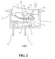
- FIG. 2 is a sectional view showing the “ON” status of the safety switch of the present invention
- FIG. 3 shows that when overloaded, a push rod locates at right side of a spring member and does not stop the clockwise movement of the spring member
- FIG. 4 is an exploded view of the safety switch in accordance with the present invention.
- a safety switch in accordance with the present invention comprises a body 1 with a top opening and a switch member 2 pivotably engaged with the top opening of the body 1 such that the switch member 2 is pivoted about a pin at a middle portion thereof.
- An extension 21 extends from a first end of an underside of the switch member 2 and a reception hole 20 is defined in an inside of the switch member 2 .
- a push rod 22 includes an insertion extending transversely from an end thereof and the insertion is pivotably inserted into the reception hole 20 .
- a stop rod 222 extends from the inside of the switch member 2 and locates at a distance from the pivot position of the push rod 22 .
- a biasing member 221 such as a torsion spring is mounted to the insertion and includes two legs, one leg contacts against the underside of the switch member 2 and the other leg is connected to the push rod 22 .
- the push rod 22 is pushed toward the stop rod 222 by the biasing member 221 .
- a first terminal 11 and a second terminal 12 extend through a bottom of the body 1 .
- a contact plate 3 which is a curved and flexible bimetallic plate and a first end of the contact plate 3 is fixed to the first terminal 11 and a second end of the contact plate 3 is a free end.
- a contact portion 31 splits from the contact plate 3 and a first contact point 311 is connected to an underside of the contact portion 31 .
- a second contact point 121 is connected to the second terminal 12 and located beneath the first contact point 311 on the contact portion 31 .
- a free end of the contact portion 31 is located above a top surface of the contact plate 3 and connected with a free first end of a U-shaped spring member 32 .
- the free end of the contact portion 31 has a tongue 312 and the free first end of the spring member 32 has a first slot 321 with which the tongue 312 is engaged.
- a second end of the spring member 32 has a second slot 322 .
- a ridge 313 extends from an inner periphery of an opening from which the contact portion 31 splits, and the ridge 313 is engaged with the second slot 322 .
- the second end of the contact plate 3 and the free end of the contact portion 31 are deformed in opposite directions when being heated.
- the extension 21 of the switch member 2 is located above the second end of the contact plate 3 and presses the second end of the contact plate 3 downward when the switch member 2 is in “OFF” position as shown in FIG. 1 .
- the spring member 32 is pushed by the push rod 22 to lower the first contact point 311 to be in contact with the second contact point 121 .
- the push rod 22 is located at right side of the spring member 32 .
- the contact portion 31 is deformed upward and the free end of the contact plate 3 is deformed downward so as to separate the two contact points 311 , 121 to cut off the circuit.
- the spring member 32 is rotated clockwise about the second end of the spring member 32 together with the upward movement of the contact portion 31 , and the push rod 22 is then pushed away to allow the movement of the spring member 32 to be completed.
- the leg contacting against the underside of the switch member 2 pushes the switch member 2 which is then pivoted to “OFF” position.
Abstract
A safety switch includes a switch member and a push rod is pivotably connected to an inside of the switch member. A biasing member pushes the push rod toward a stop rod extending from the inside of the switch member. A bi-metallic contact plate has a first end fixed to one of two terminals and a contact portion splits from the contact plate. A first contact point is connected to an underside of the contact portion and a second contact point is connected to the other terminal. A free end of the contact portion is connected with a free first end of a spring member and a second end of the spring member is connected to the contact plate. When overloaded, the contact portion and the spring member move clockwise to cut off the circuit while the push rod does not stop the clockwise movement of the spring member.
Description
1. Field of the Invention
The present invention relates to a safety switch that ensures the bimetallic plate to be deformed as desired when overloaded and the switch member is pivoted to “OFF” position.
2. The Prior Arts
A conventional switch device, especially for those switches using bimetallic plate to prevent from being burned when an overload is happened, generally includes a bimetallic plate which is deformed when overloaded so as to separate the two contact points respectively located on the bimetallic plate and one of the two terminals. Some inherent shortcomings for these conventional safety switches are experienced. There are too many parts involved in the safety switches and a longer period of time is required when assembling the switches, so this increases the cost of the products. The parts might be arranged inaccurately and affect the deformation of the bimetallic plate. Once the bimetallic plate is deformed to cut off the circuit, because of the improper arrangement of the parts as mentioned above, the bimetallic plate could deform to re-connect the two contact points to connect the circuit again. Because of the inaccuracy of the deformation of the bimetallic plate, the switch member does not set to the “OFF” position after the bimetallic plate is deformed to cut off the circuit.
Therefore, it is desired to have a safety switch that allows the bimetallic plate to deform toward a desired direction when overloaded and the bimetallic plate is freely deformed to prevent the bimetallic plate from bouncing back to re-connect the circuit again.
In accordance with an aspect of the present invention, there is provided a safety switch, which comprises a body with a switch member pivotably engaged with the top opening of the body. An extension extends from a first end of an underside of the switch member and a push rod is pivotably connected to an inside of the switch member. A stop rod extends from the inside of the switch member and locates at a distance from a pivot position of the push rod. A biasing member is connected to the push rod and pushes the push rod toward the stop rod. A first terminal and a second terminal extend through a bottom of the body. A contact plate has a first end fixed to the first terminal and a second end of the contact plate is a free end. A contact portion splits from the contact plate and a first contact point is connected to an underside of the contact portion. A free end of the contact portion is located above a top surface of the contact plate and connected with a free first end of a spring member. A second end of the spring member is connected to the contact plate. A second contact point is connected to the second terminal and locates beneath the first contact point on the contact portion. The second end of the contact plate and the free end of the contact portion are deformed in opposite directions when being heated. The push rod is located at right side of the spring member when in “ON” position so that when overloaded, the contact portion is deformed clockwise to separate the two contact points and the spring member pushes the push rod away to allow the clockwise movement of the spring member to be completed.
The main object of the present invention is to provide a safety switch which provides a push rod pivotably connected to the switch member so as to push the spring member when setting the switch in “ON” position, and the push rod does not stop the clockwise movement of the spring when overloaded.
Another object of the present invention is to provide a safety switch, wherein the switch member is automatically set at “OFF” position after overloaded.
Yet another object of the present invention is to provide a safety switch that includes less number of parts so as to have lower manufacturing cost.
The present invention will become more obvious from the following description when taken in connection with the accompanying drawings, which show, for purposes of illustration only, a preferred embodiment in accordance with the present invention.
Referring to the drawings and in particular to FIGS. 1 , 2 and 4, a safety switch in accordance with the present invention comprises a body 1 with a top opening and a switch member 2 pivotably engaged with the top opening of the body 1 such that the switch member 2 is pivoted about a pin at a middle portion thereof. An extension 21 extends from a first end of an underside of the switch member 2 and a reception hole 20 is defined in an inside of the switch member 2. A push rod 22 includes an insertion extending transversely from an end thereof and the insertion is pivotably inserted into the reception hole 20. A stop rod 222 extends from the inside of the switch member 2 and locates at a distance from the pivot position of the push rod 22. A biasing member 221 such as a torsion spring is mounted to the insertion and includes two legs, one leg contacts against the underside of the switch member 2 and the other leg is connected to the push rod 22. By this arrangement, the push rod 22 is pushed toward the stop rod 222 by the biasing member 221.
A first terminal 11 and a second terminal 12 extend through a bottom of the body 1. A contact plate 3 which is a curved and flexible bimetallic plate and a first end of the contact plate 3 is fixed to the first terminal 11 and a second end of the contact plate 3 is a free end. A contact portion 31 splits from the contact plate 3 and a first contact point 311 is connected to an underside of the contact portion 31. A second contact point 121 is connected to the second terminal 12 and located beneath the first contact point 311 on the contact portion 31. A free end of the contact portion 31 is located above a top surface of the contact plate 3 and connected with a free first end of a U-shaped spring member 32. The free end of the contact portion 31 has a tongue 312 and the free first end of the spring member 32 has a first slot 321 with which the tongue 312 is engaged. A second end of the spring member 32 has a second slot 322. A ridge 313 extends from an inner periphery of an opening from which the contact portion 31 splits, and the ridge 313 is engaged with the second slot 322. The second end of the contact plate 3 and the free end of the contact portion 31 are deformed in opposite directions when being heated.
The extension 21 of the switch member 2 is located above the second end of the contact plate 3 and presses the second end of the contact plate 3 downward when the switch member 2 is in “OFF” position as shown in FIG. 1 . When the second end of the switch member 2 is pushed downward to “ON” position, the spring member 32 is pushed by the push rod 22 to lower the first contact point 311 to be in contact with the second contact point 121. After the spring member 32 is pushed downward, the push rod 22 is located at right side of the spring member 32.
As shown in FIG. 3 , when overloaded, the contact portion 31 is deformed upward and the free end of the contact plate 3 is deformed downward so as to separate the two contact points 311, 121 to cut off the circuit. The spring member 32 is rotated clockwise about the second end of the spring member 32 together with the upward movement of the contact portion 31, and the push rod 22 is then pushed away to allow the movement of the spring member 32 to be completed. In the meanwhile, the leg contacting against the underside of the switch member 2 pushes the switch member 2 which is then pivoted to “OFF” position.
While we have shown and described the embodiment in accordance with the present invention, it should be clear to those skilled in the art that further embodiments may be made without departing from the scope of the present invention.
Claims (7)
1. A safety switch, comprising
a body with a top opening and a switch member pivotably engaged with the top opening of the body, an extension extending from a first end of an underside of the switch member and a push rod pivotably connected to an inside of the switch member, a stop rod extending from the inside of the switch member and locating at a distance from a pivot position of the push rod, a biasing member connected to the push rod and pushing the push rod toward the stop rod, a first terminal and a second terminal extending through a bottom of the body; and
a contact plate being a curved and flexible metal plate and having a first end fixed to the first terminal and a second end of the contact plate being a free end, a contact portion splitting from the contact plate and a first contact point connected to an underside of the contact portion, a free end of the contact portion located above a top surface of the contact plate and connected with a free first end of a spring member, a second end of the spring member connected to the contact plate, a second contact point connected to the second terminal and located beneath the first contact point on the contact portion, the second end of the contact plate and the free end of the contact portion being deformed in opposite directions when being heated, and the extension of the switch member located above the second end of the contact plate.
2. The safety switch as claimed in claim 1 , wherein the free end of the contact portion has a tongue and the free first end of the spring member has a first slot with which the tongue is engaged.
3. The safety switch as claimed in claim 1 , wherein the second end of the spring member has a second slot, and a ridge extends from an inner periphery of an opening from which the contact portion splits and the ridge is engaged with the second slot.
4. The safety switch as claimed in claim 1 , wherein the spring member is a U-shaped member.
5. The safety switch as claimed in claim 1 , wherein the contact plate is a bi-metallic plate.
6. The safety switch as claimed in claim 1 , wherein a reception hole is defined in the inside of the switch member and the push rod includes an insertion which is inserted into the reception hole.
7. The safety switch as claimed in claim 6 , wherein the biasing member is a torsion spring, which is mounted to the insertion and includes two legs, one leg contacting against the underside of the switch member and the other leg being connected to the push rod.
Priority Applications (1)
| Application Number | Priority Date | Filing Date | Title |
|---|---|---|---|
| US11/203,635 US7304560B2 (en) | 2005-08-12 | 2005-08-12 | Safety switches |
Applications Claiming Priority (1)
| Application Number | Priority Date | Filing Date | Title |
|---|---|---|---|
| US11/203,635 US7304560B2 (en) | 2005-08-12 | 2005-08-12 | Safety switches |
Publications (2)
| Publication Number | Publication Date |
|---|---|
| US20070035377A1 US20070035377A1 (en) | 2007-02-15 |
| US7304560B2 true US7304560B2 (en) | 2007-12-04 |
Family
ID=37742021
Family Applications (1)
| Application Number | Title | Priority Date | Filing Date |
|---|---|---|---|
| US11/203,635 Expired - Fee Related US7304560B2 (en) | 2005-08-12 | 2005-08-12 | Safety switches |
Country Status (1)
| Country | Link |
|---|---|
| US (1) | US7304560B2 (en) |
Cited By (5)
| Publication number | Priority date | Publication date | Assignee | Title |
|---|---|---|---|---|
| US20080284556A1 (en) * | 2007-05-18 | 2008-11-20 | Sun-Lite Sockets Industry Inc. | Current breaker |
| US20110080250A1 (en) * | 2009-10-07 | 2011-04-07 | Tsan-Chi Chen | Overcurrent protection device having free trip mechanism |
| CN107331575A (en) * | 2017-08-19 | 2017-11-07 | 佛山市汇莱德电器有限公司 | The coupler seat of honour of overcurrent protection homing position type |
| US10529513B1 (en) * | 2018-10-02 | 2020-01-07 | Green Idea Tech Inc. | Overheating destructive switch |
| US11024478B2 (en) * | 2018-10-02 | 2021-06-01 | Green Idea Tech Inc. | Overheating destructive disconnecting method for switch |
Families Citing this family (1)
| Publication number | Priority date | Publication date | Assignee | Title |
|---|---|---|---|---|
| CN103545144A (en) * | 2013-07-25 | 2014-01-29 | 扬州宝珠电器有限公司 | Spring-locking type manual reset protector |
Citations (38)
| Publication number | Priority date | Publication date | Assignee | Title |
|---|---|---|---|---|
| US3932829A (en) * | 1973-10-25 | 1976-01-13 | Ellenberger & Poensgen Gmbh | Excess current switch |
| US4258349A (en) * | 1978-09-05 | 1981-03-24 | Weber A.G. Fabrik Elektrotechnischer Artikel Und Apparate | Double-pole rocker switch with thermal protection |
| US4329669A (en) * | 1979-07-13 | 1982-05-11 | Ellenberger & Poensgen Gmbh | Circuit breaker with auxiliary tripping unit |
| US4338586A (en) * | 1980-09-03 | 1982-07-06 | Heinemann Electric Company | Circuit protector having a slidable latch |
| US4345233A (en) * | 1981-03-02 | 1982-08-17 | Eaton Corporation | Manual switch with timed electro-thermal latch release |
| US4528538A (en) * | 1984-01-13 | 1985-07-09 | Andersen James H | Combined switch and circuit breaker |
| FR2605142A1 (en) * | 1986-10-14 | 1988-04-15 | Mors | Electric switch provided with means of protection, especially against water spray |
| US4833439A (en) * | 1985-11-27 | 1989-05-23 | Slater Electric, Inc. | Unitary switch and circuit breaker |
| US4922219A (en) * | 1989-07-17 | 1990-05-01 | Mechanical Products, Inc. | Circuit breaker |
| US5089799A (en) * | 1991-01-25 | 1992-02-18 | Sorenson Richard W | Thermal switch/breaker |
| US5223813A (en) * | 1991-11-18 | 1993-06-29 | Potter & Brumfield, Inc. | Circuit breaker rocker actuator switch |
| US5262748A (en) * | 1992-01-13 | 1993-11-16 | Tsung Mou Yu | Fuseless breaking switch |
| US5264817A (en) * | 1993-02-11 | 1993-11-23 | Sorenson Richard W | Thermal circuit protective device |
| US5491460A (en) * | 1993-03-17 | 1996-02-13 | Ellenberger & Poensgen Gmbh | Instrument switch having integrated overcurrent protection |
| US5539371A (en) * | 1995-09-08 | 1996-07-23 | Yu; Tsung-Mou | Fuseless breaking switch |
| US5760672A (en) * | 1997-05-02 | 1998-06-02 | Wang; Ming-Shan | Safety switch built-in with protecting circuit |
| US5892426A (en) * | 1998-06-12 | 1999-04-06 | Huang; Tse-Chuan | Safety switch with security structure |
| US6275134B1 (en) * | 2000-03-01 | 2001-08-14 | Tsan-Chi Chen | Safety switch with a rocker type actuator and trip-off contact |
| US6307460B1 (en) * | 2000-02-01 | 2001-10-23 | Tsung-Mou Yu | Power switch device |
| US6400250B1 (en) * | 2000-07-14 | 2002-06-04 | Tsung-Mou Yu | Safety switch |
| US6445273B1 (en) * | 1999-10-29 | 2002-09-03 | Tsung-Mou Yu | Overload-protection push-button switch with automatic resetting mechanism |
| US6456185B1 (en) * | 1999-06-24 | 2002-09-24 | Tsung-Mou Yu | Push-button switch with overload protection |
| US6512441B1 (en) * | 1999-06-24 | 2003-01-28 | Tsung-Mou Yu | Push-button switch of overload protection (II) |
| US6525639B1 (en) * | 2001-08-15 | 2003-02-25 | Tsang-I Cheng | Power source electrical switch |
| US6552644B2 (en) * | 2001-07-17 | 2003-04-22 | Tsung-Mou Yu | Safety press-button switch |
| US6563414B2 (en) * | 2001-04-19 | 2003-05-13 | Tsung-Mou Yu | Switch having a bimetal plate with two legs |
| US6577221B1 (en) * | 2001-11-30 | 2003-06-10 | Ming-Shan Wang | Safety switch |
| US20030160679A1 (en) * | 2002-02-26 | 2003-08-28 | Tsung-Mou Yu | Switch with adjustable spring |
| US6621402B2 (en) * | 2002-01-23 | 2003-09-16 | Albert Huang | Circuit breaker |
| US6664884B1 (en) * | 2002-08-24 | 2003-12-16 | Tsung-Mou Yu | Dual-circuit switch structure with overload protection |
| US6674033B1 (en) * | 2002-08-21 | 2004-01-06 | Ming-Shan Wang | Press button type safety switch |
| US6714116B1 (en) * | 2002-01-22 | 2004-03-30 | Rototech Electrical Components, Inc. | Circuit breaker switch |
| US6734779B2 (en) * | 2002-08-24 | 2004-05-11 | Tsung-Mou Yu | Switch structure with overload protection |
| US6788186B1 (en) * | 2003-05-31 | 2004-09-07 | Tsung-Mou Yu | Activation mechanism for switch devices |
| US6864453B1 (en) * | 2004-07-08 | 2005-03-08 | Tsung-Mou Yu | Protection mechanism for switch |
| US20050140489A1 (en) * | 2003-12-25 | 2005-06-30 | Wan-Kuo Kuo | Circuit breaker structure |
| US6940389B1 (en) * | 2004-05-14 | 2005-09-06 | Tsung-Mou Yu | Mechanism for ensuring bimetallic plate to be deformed without barrier |
| US7030726B2 (en) * | 2004-07-10 | 2006-04-18 | Tsung-Mou Yu | Protection mechanism for switches |
-
2005
- 2005-08-12 US US11/203,635 patent/US7304560B2/en not_active Expired - Fee Related
Patent Citations (39)
| Publication number | Priority date | Publication date | Assignee | Title |
|---|---|---|---|---|
| US3932829A (en) * | 1973-10-25 | 1976-01-13 | Ellenberger & Poensgen Gmbh | Excess current switch |
| US4258349A (en) * | 1978-09-05 | 1981-03-24 | Weber A.G. Fabrik Elektrotechnischer Artikel Und Apparate | Double-pole rocker switch with thermal protection |
| US4329669A (en) * | 1979-07-13 | 1982-05-11 | Ellenberger & Poensgen Gmbh | Circuit breaker with auxiliary tripping unit |
| US4338586A (en) * | 1980-09-03 | 1982-07-06 | Heinemann Electric Company | Circuit protector having a slidable latch |
| US4345233A (en) * | 1981-03-02 | 1982-08-17 | Eaton Corporation | Manual switch with timed electro-thermal latch release |
| US4528538A (en) * | 1984-01-13 | 1985-07-09 | Andersen James H | Combined switch and circuit breaker |
| US4833439A (en) * | 1985-11-27 | 1989-05-23 | Slater Electric, Inc. | Unitary switch and circuit breaker |
| FR2605142A1 (en) * | 1986-10-14 | 1988-04-15 | Mors | Electric switch provided with means of protection, especially against water spray |
| US4922219A (en) * | 1989-07-17 | 1990-05-01 | Mechanical Products, Inc. | Circuit breaker |
| US5089799A (en) * | 1991-01-25 | 1992-02-18 | Sorenson Richard W | Thermal switch/breaker |
| US5223813A (en) * | 1991-11-18 | 1993-06-29 | Potter & Brumfield, Inc. | Circuit breaker rocker actuator switch |
| US5262748A (en) * | 1992-01-13 | 1993-11-16 | Tsung Mou Yu | Fuseless breaking switch |
| US5264817A (en) * | 1993-02-11 | 1993-11-23 | Sorenson Richard W | Thermal circuit protective device |
| US5491460A (en) * | 1993-03-17 | 1996-02-13 | Ellenberger & Poensgen Gmbh | Instrument switch having integrated overcurrent protection |
| US5539371A (en) * | 1995-09-08 | 1996-07-23 | Yu; Tsung-Mou | Fuseless breaking switch |
| US5760672A (en) * | 1997-05-02 | 1998-06-02 | Wang; Ming-Shan | Safety switch built-in with protecting circuit |
| US5892426A (en) * | 1998-06-12 | 1999-04-06 | Huang; Tse-Chuan | Safety switch with security structure |
| US6512441B1 (en) * | 1999-06-24 | 2003-01-28 | Tsung-Mou Yu | Push-button switch of overload protection (II) |
| US6456185B1 (en) * | 1999-06-24 | 2002-09-24 | Tsung-Mou Yu | Push-button switch with overload protection |
| US6445273B1 (en) * | 1999-10-29 | 2002-09-03 | Tsung-Mou Yu | Overload-protection push-button switch with automatic resetting mechanism |
| US6307460B1 (en) * | 2000-02-01 | 2001-10-23 | Tsung-Mou Yu | Power switch device |
| US6275134B1 (en) * | 2000-03-01 | 2001-08-14 | Tsan-Chi Chen | Safety switch with a rocker type actuator and trip-off contact |
| US6400250B1 (en) * | 2000-07-14 | 2002-06-04 | Tsung-Mou Yu | Safety switch |
| US6563414B2 (en) * | 2001-04-19 | 2003-05-13 | Tsung-Mou Yu | Switch having a bimetal plate with two legs |
| US6552644B2 (en) * | 2001-07-17 | 2003-04-22 | Tsung-Mou Yu | Safety press-button switch |
| US6525639B1 (en) * | 2001-08-15 | 2003-02-25 | Tsang-I Cheng | Power source electrical switch |
| US6577221B1 (en) * | 2001-11-30 | 2003-06-10 | Ming-Shan Wang | Safety switch |
| US6714116B1 (en) * | 2002-01-22 | 2004-03-30 | Rototech Electrical Components, Inc. | Circuit breaker switch |
| US6621402B2 (en) * | 2002-01-23 | 2003-09-16 | Albert Huang | Circuit breaker |
| US6617952B1 (en) * | 2002-02-26 | 2003-09-09 | Tsung-Mou Yu | Switch with adjustable spring |
| US20030160679A1 (en) * | 2002-02-26 | 2003-08-28 | Tsung-Mou Yu | Switch with adjustable spring |
| US6674033B1 (en) * | 2002-08-21 | 2004-01-06 | Ming-Shan Wang | Press button type safety switch |
| US6664884B1 (en) * | 2002-08-24 | 2003-12-16 | Tsung-Mou Yu | Dual-circuit switch structure with overload protection |
| US6734779B2 (en) * | 2002-08-24 | 2004-05-11 | Tsung-Mou Yu | Switch structure with overload protection |
| US6788186B1 (en) * | 2003-05-31 | 2004-09-07 | Tsung-Mou Yu | Activation mechanism for switch devices |
| US20050140489A1 (en) * | 2003-12-25 | 2005-06-30 | Wan-Kuo Kuo | Circuit breaker structure |
| US6940389B1 (en) * | 2004-05-14 | 2005-09-06 | Tsung-Mou Yu | Mechanism for ensuring bimetallic plate to be deformed without barrier |
| US6864453B1 (en) * | 2004-07-08 | 2005-03-08 | Tsung-Mou Yu | Protection mechanism for switch |
| US7030726B2 (en) * | 2004-07-10 | 2006-04-18 | Tsung-Mou Yu | Protection mechanism for switches |
Cited By (7)
| Publication number | Priority date | Publication date | Assignee | Title |
|---|---|---|---|---|
| US20080284556A1 (en) * | 2007-05-18 | 2008-11-20 | Sun-Lite Sockets Industry Inc. | Current breaker |
| US20110080250A1 (en) * | 2009-10-07 | 2011-04-07 | Tsan-Chi Chen | Overcurrent protection device having free trip mechanism |
| US8154375B2 (en) * | 2009-10-07 | 2012-04-10 | Tsan-Chi Chen | Overcurrent protection device having trip free mechanism |
| CN107331575A (en) * | 2017-08-19 | 2017-11-07 | 佛山市汇莱德电器有限公司 | The coupler seat of honour of overcurrent protection homing position type |
| CN107331575B (en) * | 2017-08-19 | 2020-07-24 | 广东汇莱德温控器有限公司 | Overcurrent protection reset type coupler upper seat |
| US10529513B1 (en) * | 2018-10-02 | 2020-01-07 | Green Idea Tech Inc. | Overheating destructive switch |
| US11024478B2 (en) * | 2018-10-02 | 2021-06-01 | Green Idea Tech Inc. | Overheating destructive disconnecting method for switch |
Also Published As
| Publication number | Publication date |
|---|---|
| US20070035377A1 (en) | 2007-02-15 |
Similar Documents
| Publication | Publication Date | Title |
|---|---|---|
| US7248140B2 (en) | Adjustable safety switch | |
| US7292129B2 (en) | Protection device for switches | |
| US7307506B2 (en) | Safety switches | |
| US7304560B2 (en) | Safety switches | |
| US5828284A (en) | Circuit overload protective device | |
| US20060220779A1 (en) | Adjustable safety switch | |
| US6307460B1 (en) | Power switch device | |
| US7196280B2 (en) | Miniaturized electric switch | |
| US5929742A (en) | Trip-free, manual reset thermostat | |
| US7479868B2 (en) | Trip-free manual reset thermostat | |
| US20060082432A1 (en) | Manual-reset thermostat | |
| US7208693B1 (en) | Safety device for dual-circuit switch | |
| US6377158B1 (en) | Push button current cut-off safety switch | |
| US7656268B2 (en) | Safety switch | |
| US7116207B1 (en) | Safety device for switches | |
| US6377159B1 (en) | Push button circuit breaker switch | |
| US7583175B2 (en) | Safety switch | |
| EP2003670B1 (en) | Compound operation input device | |
| US7079002B1 (en) | Safety switch | |
| US7583174B2 (en) | Safety switch | |
| US5875887A (en) | Contact switch assembly having a conductor that holds a movable contact plate | |
| EP2779196B1 (en) | Miniature circuit breaker | |
| US6713704B1 (en) | Pushbutton assembly | |
| JP4720737B2 (en) | Leaf switch | |
| US7307505B2 (en) | Safety switches |
Legal Events
| Date | Code | Title | Description |
|---|---|---|---|
| STCF | Information on status: patent grant |
Free format text: PATENTED CASE |
|
| FPAY | Fee payment |
Year of fee payment: 4 |
|
| FPAY | Fee payment |
Year of fee payment: 8 |
|
| FEPP | Fee payment procedure |
Free format text: MAINTENANCE FEE REMINDER MAILED (ORIGINAL EVENT CODE: REM.); ENTITY STATUS OF PATENT OWNER: SMALL ENTITY |
|
| LAPS | Lapse for failure to pay maintenance fees |
Free format text: PATENT EXPIRED FOR FAILURE TO PAY MAINTENANCE FEES (ORIGINAL EVENT CODE: EXP.); ENTITY STATUS OF PATENT OWNER: SMALL ENTITY |
|
| STCH | Information on status: patent discontinuation |
Free format text: PATENT EXPIRED DUE TO NONPAYMENT OF MAINTENANCE FEES UNDER 37 CFR 1.362 |
|
| FP | Lapsed due to failure to pay maintenance fee |
Effective date: 20191204 |