US7304618B2 - Remote display for portable meter - Google Patents

Remote display for portable meter Download PDF

Info

Publication number
US7304618B2
US7304618B2 US10/368,040 US36804003A US7304618B2 US 7304618 B2 US7304618 B2 US 7304618B2 US 36804003 A US36804003 A US 36804003A US 7304618 B2 US7304618 B2 US 7304618B2
Authority
US
United States
Prior art keywords
remote display
portable meter
display
remote
user
Prior art date
Legal status (The legal status is an assumption and is not a legal conclusion. Google has not performed a legal analysis and makes no representation as to the accuracy of the status listed.)
Active, expires
Application number
US10/368,040
Other versions
US20040160410A1 (en
Inventor
Henry J. Plathe
Current Assignee (The listed assignees may be inaccurate. Google has not performed a legal analysis and makes no representation or warranty as to the accuracy of the list.)
Individual
Original Assignee
Individual
Priority date (The priority date is an assumption and is not a legal conclusion. Google has not performed a legal analysis and makes no representation as to the accuracy of the date listed.)
Filing date
Publication date
Application filed by Individual filed Critical Individual
Priority to US10/368,040 priority Critical patent/US7304618B2/en
Priority to PCT/US2004/004368 priority patent/WO2004075150A2/en
Publication of US20040160410A1 publication Critical patent/US20040160410A1/en
Application granted granted Critical
Publication of US7304618B2 publication Critical patent/US7304618B2/en
Assigned to FLUKE CORPORATION reassignment FLUKE CORPORATION LICENSE (SEE DOCUMENT FOR DETAILS). Assignors: PLATHE, HENRY J., MR.
Active legal-status Critical Current
Adjusted expiration legal-status Critical

Links

Images

Classifications

    • GPHYSICS
    • G01MEASURING; TESTING
    • G01RMEASURING ELECTRIC VARIABLES; MEASURING MAGNETIC VARIABLES
    • G01R1/00Details of instruments or arrangements of the types included in groups G01R5/00 - G01R13/00 and G01R31/00
    • G01R1/02General constructional details
    • G01R1/04Housings; Supporting members; Arrangements of terminals
    • GPHYSICS
    • G01MEASURING; TESTING
    • G01RMEASURING ELECTRIC VARIABLES; MEASURING MAGNETIC VARIABLES
    • G01R1/00Details of instruments or arrangements of the types included in groups G01R5/00 - G01R13/00 and G01R31/00
    • G01R1/02General constructional details
    • G01R1/06Measuring leads; Measuring probes
    • G01R1/067Measuring probes
    • G01R1/06788Hand-held or hand-manipulated probes, e.g. for oscilloscopes or for portable test instruments
    • GPHYSICS
    • G01MEASURING; TESTING
    • G01RMEASURING ELECTRIC VARIABLES; MEASURING MAGNETIC VARIABLES
    • G01R13/00Arrangements for displaying electric variables or waveforms
    • GPHYSICS
    • G01MEASURING; TESTING
    • G01RMEASURING ELECTRIC VARIABLES; MEASURING MAGNETIC VARIABLES
    • G01R1/00Details of instruments or arrangements of the types included in groups G01R5/00 - G01R13/00 and G01R31/00
    • G01R1/02General constructional details
    • G01R1/025General constructional details concerning dedicated user interfaces, e.g. GUI, or dedicated keyboards
    • GPHYSICS
    • G01MEASURING; TESTING
    • G01RMEASURING ELECTRIC VARIABLES; MEASURING MAGNETIC VARIABLES
    • G01R15/00Details of measuring arrangements of the types provided for in groups G01R17/00 - G01R29/00, G01R33/00 - G01R33/26 or G01R35/00
    • G01R15/12Circuits for multi-testers, i.e. multimeters, e.g. for measuring voltage, current, or impedance at will
    • G01R15/125Circuits for multi-testers, i.e. multimeters, e.g. for measuring voltage, current, or impedance at will for digital multimeters
    • GPHYSICS
    • G06COMPUTING; CALCULATING OR COUNTING
    • G06FELECTRIC DIGITAL DATA PROCESSING
    • G06F3/00Input arrangements for transferring data to be processed into a form capable of being handled by the computer; Output arrangements for transferring data from processing unit to output unit, e.g. interface arrangements
    • G06F3/14Digital output to display device ; Cooperation and interconnection of the display device with other functional units
    • G06F3/147Digital output to display device ; Cooperation and interconnection of the display device with other functional units using display panels

Definitions

  • This invention relates to portable meters, such as meters capable of obtaining electrical measurements. Specifically, the invention relates to the display of information obtained by portable meters.
  • portable meters are often a cumbersome processes.
  • a user typically locates a place to rest the portable meter so that the user can observe the display on the portable meter. The user then maneuvers two leads into position to contact the electrical apparatus to be measured, while simultaneously looking to the portable meter to read the information from the display.
  • a user may need to take time to locate the portable meter close to the electrical apparatus, such that the wires connecting the leads to the portable meter reach the electrical apparatus.
  • the portable meter should be within view of the user, oriented so that the meter's display faces the user, while the user is holding the leads in position on the electrical apparatus.
  • the present invention addresses the difficulty of the prior art by providing a remote display for use with the portable meter.
  • the remote display may be mounted to an extremity, such as a wrist or hand, of a user.
  • the user can simultaneously operate two leads while reading the remote display, without having to look away from the area in which the user is holding the leads. Therefore, safety and efficiency can be enhanced, as the user can quickly locate the leads and obtain information from the portable meter by viewing the remote display, without needing to turn away from the general area in which the leads are being held.
  • the portable meter may be mounted to the user, such as by a belt clip.
  • the user can quickly locate one or more leads on an electrical apparatus and rapidly view the information obtained by the portable meter on the remote display, without first positioning the portable meter on a nearby surface. Because the portable meter is mounted to the user in this case, the wires connecting the leads to the portable meter can be sized to accommodate the reach of the user.
  • controls may be positioned on the remote display, a lead and/or on the portable meter for control of the display mode of the remote display or various operations of the portable meter.
  • a remote display for a portable meter capable of obtaining an electrical measurement having a display panel configured to remotely display information obtained from the portable meter.
  • a case is provided for accommodating the display panel and a first port is provided to be coupled to the display panel and configured to receive data corresponding to the information from the portable meter.
  • a remote viewing apparatus for use with a portable meter that is capable of obtaining an electrical measurement.
  • a remote display which is adapted to display the electrical measurement is provided along with a remote display holder.
  • the remote display holder is coupled to the remote display and is adapted to enable the remote display to be mounted to a user.
  • a system for obtaining electrical measurements includes a remote display and a portable meter capable of obtaining an electrical measurement.
  • the remote display is remotely located from the portable meter and is coupled to the portable meter.
  • the remote display is also capable of displaying information obtained by the portable meter.
  • a method for configuring a remote display.
  • the remote display is coupled to a portable meter.
  • the method includes the steps of mounting a remote display to an extremity of a user by the use of a remote display holder and coupling a remote display to the portable meter.
  • FIG. 1 is a description of a system for obtaining electrical measurements according to an embodiment of the invention
  • FIG. 2 is an illustration of a portable meter according to an embodiment of the invention
  • FIGS. 3-6 are illustrations of various examples of remote displays according to embodiments of the inventions.
  • FIG. 7 is an illustration of a remote display holder in the form of a wristband according to an embodiment of the invention.
  • FIGS. 8A , 8 B and 9 are illustrations of a remote display holder in the form of a glove according to an embodiment of the invention.
  • FIG. 10 is an illustration of a lead coupled to a remote display according to an embodiment of the invention.
  • FIG. 11 is an illustration of a lead incorporating a remote display according to an embodiment of the invention.
  • FIG. 12 is an illustration of a method according to an embodiment of the invention.
  • a system 100 for obtaining electrical measurements is illustrated by way of example in FIG. 1 .
  • a remote display 400 is provided for use with a portable meter 200 .
  • the portable meter 200 may be similar to any of a wide variety of portable meters, such as a multimeter capable of obtaining electrical measurements.
  • portable meter is intended to include meters and test devices that are portable.
  • Portable meters and test devices may be configured for handheld use and may optionally be placed on a desktop or test bench. Often, portable meters will be configured to be used with leads, although the invention is not so limited.
  • portable meters include, but are not limited to, test devices to analyze data transmission on network cabling and/or multimeters. Examples of multimeters on which the portable meter 200 may be based include the FLUKE 189 Digital Multimeter from FLUKE Corporation of Everett, Washington, the True RMS Reading Multimeter, part number 93-105/00408, available from GREENLEE TEXTRON Inc.
  • the portable meter 200 may optionally be provided with a display 210 and controls 220 to provide control inputs to operate the functions of the portable meter 200 and/or a remote display 400 .
  • Lead ports 230 may also be provided for attaching leads 300 , as is typically done by the use of a lead wire 310 associated with each lead 300 .
  • a remote display interface port 240 is also provided for communication with the remote display 400 .
  • the remote display 400 includes a display panel 430 and a communications port 410 for communication coupling with the remote display interface port 240 of the portable meter 200 .
  • a remote display cable 412 may be used to couple the communications port 410 to the remote display interface port 240 .
  • a control 420 may be provided on the remote display 400 to provide a control input for controlling a display mode of the remote display 400 and/or operation of the portable meter 200 .
  • a control 320 may also be provided on a lead 300 for controlling a display mode of the remote display 400 and/or operation of the portable meter 200 .
  • the system 100 may also include a portable meter holder 500 for mounting the portable meter 100 to a user.
  • a remote display holder 600 may also be provided for mounting the remote display 400 to a user.
  • the remote display holder 600 is configured to mount the remote display 400 to an extremity 700 of a user, such as a wrist and/or hand.
  • the display 210 of the portable meter 200 is shown by way of example.
  • the display 210 may be tailored for specific applications for which the portable meter 200 is intended.
  • the display 210 may be omitted from the portable meter 200 entirely.
  • the remote display 400 may be configured to be attachable to and detachable from the portable meter 200 . In such a case, the remote display 400 could optionally be able to be located in the position of the display 210 of FIG. 2 when attached to the portable meter 200 .
  • the remote display 400 could be held in place by a hook and loop fastener, a latch, a clip, a snap, or other devices able to mount the remote display 400 to the portable meter 200 . When removed from this position, the remote display 400 would provide the capability of remotely displaying information obtained from the portable meter.
  • the remote display interface port 240 may be configured to provide a wired connection to the remote display 400 by the use of a remote display cable 412 , as illustrated in FIG. 1 .
  • the remote display interface port 240 may be configured to provide a wireless coupling for communication to the remote display 400 .
  • a wireless coupling may be formed in a wide variety of ways. Some examples of wireless couplings include infrared (IR) communications or other invisible or visible light signals as well as radio frequency (RF) signals, or other electromagnetic wavelength communications and other wireless coupling types known in the art for communication between electronic devices.
  • the remote display interface port 240 may be configured to provide the same display signals to the remote display 400 that are provided to the display 210 of the portable meter 200 .
  • the portable meter 200 may be configured to enable different information and/or display signals to be provided to the remote display interface port 240 for use by the remote display 400 .
  • the display signals that would typically be provided to the display 210 could be provided to the remote display interface port 240 for use by the remote display 400 .
  • the remote display interface port 240 may also be configured to send and/or receive information relating to control inputs that may be activated by controls on the portable meter 200 , the remote display 400 and/or a lead 300 .
  • the one or more lead ports 230 may also be configured to send and/or receive information relating to control inputs that may be activated by controls on one or more leads 300 . It is understood that the controls 220 may be omitted from the portable meter 200 , as optional controls on the remote display 400 and/or leads 300 may be used to control the portable meter 200 .
  • the lead 300 may be any of a wide variety of leads known in the art. Examples include probe leads, alligator-clip leads, and leads that can be used to obtain other measurements. Examples include leads for measuring temperature, radio frequency (RF) signals and luminance.
  • RF radio frequency
  • the portable meter holder 500 may be provided to mount the portable meter 200 to a user.
  • portable meter holders 500 include belt loops, belt clips, shoulder straps, or other devices known in the art for mounting a device to a user.
  • the portable meter holder 500 may include the use of an adhesive or strapping or other fastening devices, such as hook and loop fasteners, such as fasteners available from VELCRO Corporation to secure the portable meter 200 .
  • the portable meter holder 500 may optionally use a similar fastening device as is used between the remote display 400 and portable meter 200 .
  • a hook and loop fastener may be used in both cases, allowing a user to detach the remote display 400 from the portable meter 200 and attach the remote display 400 to the portable meter holder 500 .
  • FIGS. 3-6 Various examples of remote displays 400 are shown in FIGS. 3-6 .
  • a remote display 400 A is illustrated having a display panel 430 accommodated within a case 440 .
  • a communications port 410 is provided for communication with the portable meter 200 .
  • the portable meter 200 and remote display 400 may communicate via a remote display cable 412 or via wireless coupling.
  • the communications port 410 would be configured for the appropriate type of communications with the portable meter 200 .
  • the communications port 410 may be entirely internal to the remote display 400 , such as for use with a wireless coupling.
  • the case 440 of the remote display 200 may be a rigid or flexible case, as appropriate for accommodating the display panel 430 .
  • the case 440 may encapsulate the display panel 430 or may be configured to extend along only a portion of the display panel 430 .
  • the case 440 is intended to provide a structural link between the communications port 410 and the display panel 430 .
  • the display panel 430 may be formed of a wide variety of display types. For example, light emitting diodes or liquid crystal displays may be used, as well other display technologies known in the art, such as plasma displays. Other types of display panels may be apparent to one of skill in the art upon review of this description and are to be considered within the scope of the invention.
  • the display panel 430 may be configured to display information obtained by the portable meter 200 . The information may be displayed in a variety of forms, including by way of example, digital, analog and/or graphical. It is understood that a combination of one or more of various types of display formats may be used in simultaneous or sequential combination.
  • FIG. 4 illustrates a remote display 400 B having a digital display 214 in combination with unit indicators 212 . It is understood that one or more of the unit indicators 212 may be displayed at any time, and that unit indicators for voltage, resistance and current are illustrated simultaneously in FIG. 4 for purposes of illustration.
  • the remote display 400 B of FIG. 4 further illustrates a second communications port 411 that may be used in place of or in addition to the communications port 410 .
  • One, two, three or more communications ports may be provided at various locations on or within the remote display 400 for enabling a plurality of mounting options for the remote display 400 .
  • the remote display 400 B also illustrates a plurality of controls 420 that may be provided with the remote display 400 for controlling a display mode of the remote display 400 and/or controlling the operation of the portable meter 200 by way of the communication with the portable meter 200 .
  • the controls 420 may be any of a wide variety of input devices. Examples include, but are not limited to, a button, a switch, a touch screen, a dial, a knob, a keypad, a joystick and/or a microphone. The microphone may be configured to recognize different sound levels or be equipped with a voice recognition capability. It is understood that the remote display may be provided with any combination of one or more controls 420 , or may not be provided with a control 420 . Also, the controls 420 are not limited to a front surface of the remote display, and may be provided at any location on the remote display.
  • FIG. 5 illustrates a further example of a remote display 400 C.
  • the remote display 400 C includes various features of the example remote displays 400 of FIGS. 3 and 4 , while adding a lead port 450 .
  • the lead port 450 enables a user to couple a lead 300 directly to the remote display 400 .
  • Such a configuration allows for the coupling between the remote display 400 and portable meter 200 to serve as the communications path for the lead 300 and the portable meter 200 .
  • Such an arrangement may reduce the number of wires to be managed by a user and/or may shorten the length of wires, because a short lead wire 310 may be used for the lead 300 held by the user's extremity at which the remote display 400 is mounted. Whereas a longer lead wire 310 would be required if the lead wire 310 extended all the way back to the portable meter 200 , which may, be mounted on the user's waist.
  • One or more lead ports 450 may be mounted in any location on the remote display.
  • the remote display 400 C of FIG. 5 also provides a further example of a display panel 430 C in the form of a combination display.
  • the display panel 430 C shows an example of the simultaneous use of a digital display 214 with an analog display 216 in combination with a variety of unit indicators 212 and other status indicators 218 , such as those indicating whether the portable meter 200 is in an auto-ranging mode or whether the portable meter 200 will emit audible signals and a battery status indicator for the portable meter 200 .
  • These illustrated examples are not limiting, and the invention can include a wide variety of indicators.
  • the remote display 400 C may also be provided with a light 470 to enhance viewing of the display panel 430 C and/or controls 420 in low-light conditions.
  • the light 470 may be a wide variety of lights, including direct illumination and back lights and others known in the art for illuminating a display panel.
  • FIG. 6 illustrates a further example of the remote display according to another embodiment of the invention.
  • a remote display 400 D is illustrated having the display 430 C described above in relation to FIG. 5 and a case 440 D that is configured for wireless communication with the portable meter 200 .
  • the remote display 400 D of FIG. 5 is provided with an optional glare shield 460 that may be fixedly mounted or removably mounted to the case 440 D to aid in reducing glare on the display panel 430 C.
  • the remote display 400 may optionally be mounted to a user.
  • Various embodiments of remote display holders 600 are shown in FIGS. 7-11 .
  • a remote display holder 600 A is shown in the form of a wristband to which a remote display 400 is mounted.
  • the wristband is illustrated on an extremity 700 of a user.
  • the remote display 400 may be coupled with the remote display holder 600 A by the use of an adhesive, a hook and loop fastener and/or stitching of material.
  • the material may be material forming the remote display holder 600 and/or material encasing or surrounding a portion of the remote display 400 and mated to or forming a part of the remote display holder 600 .
  • the remote display holder 600 may be formed of a wide variety of materials including various fabrics, leathers, plastics, rubbers or other items. Examples include materials typically used in the construction of wristbands and gloves known in the art.
  • a remote display holder 600 B is provided in the form of a glove. As illustrated by way of example in FIGS. 8A , 8 B and 9 , the remote display holder 600 B is formed as an open-palm glove arranged to be coupled to a wrist 710 of a user and at least one finger 720 of a user. Coupled to the remote display 600 is a remote display 400 .
  • the remote display 400 may be coupled to the remote display holder 600 B of FIGS. 8A , 8 B and 9 in a wide variety of ways; such as the examples discussed above in relation to the remote display holder 600 A of FIG. 7 .
  • the remote display holder 600 B in the form of a glove may provide a variety of mounting positions for the remote display 400 .
  • the remote display 400 may be configured to include a remote display cable 412 connected to the communications port 410 to locate the remote display 400 proximate to a thumb and a back of the hand of the user.
  • One example of such a location of the remote display 400 is to longitudinally orient the remote display 400 between a user's wrist 710 and forefinger 720 , as shown in FIG. 8A . This arrangement may be desirable if the user is working to obtain measurements at or below an eye-level of the user.
  • FIG. 8A This arrangement may be desirable if the user is working to obtain measurements at or below an eye-level of the user.
  • the remote display 400 may be configured with the remote display cable 412 coupled to the second communication port 411 .
  • the remote display 400 may be located transversely between a user's wrist 710 and forefinger 720 .
  • a communication port 410 may be located at an opposite end of the remote display 400 in addition to or in place of the illustrated communication ports.
  • the remote display 400 may be easily configured for use on another hand of the user by the use of an appropriate remote display holder 600 , such as a glove formed for a right hand. It is understood that a wireless coupling may be used between the remote display 400 and portable meter 200 .
  • the remote display holders 600 illustrated in FIGS. 7-9 may be provided to conveniently locate a remote display 400 , while allowing a user to manipulate one or more leads 300 .
  • the remote display holder 600 B of FIGS. 8A , 8 B and 9 is configured to be secured about a user's wrist 710 and at least one finger 720 , while not encasing the finger 720 , thereby retaining the user's ability to touch the lead and/or other objects without interference from the remote display holder 600 B. It is understood that the invention is not so limited and any form of glove may be used in combination with the remote display 400 , including gloves fully enclosing a user's hand and/or not coupled to a user's wrist.
  • FIG. 10 illustrates a lead 300 also operating as a remote display holder 600 .
  • a remote display 400 is coupled to the lead 300 in any of a variety of ways, such as examples described above in relation to other remote display holders.
  • the coupling may be configured to allow the remote display 400 to be removable from the lead 300 .
  • the remote display 400 may be fixedly secured to the lead 300 .
  • Leads 300 may or may not operate as a remote display holder 600 .
  • a remote display 400 may be incorporated within the lead 300 .
  • the lead 300 may optionally serve as a case for the display panel of the remote display 400 .
  • the embodiment of FIG. 11 further illustrates a control 320 provided on the lead 300 .
  • the control 320 may be used to control a display mode of the remote display 400 and/or various functions of the portable meter 200 .
  • a remote display cable may be configured within the lead wire 310 and/or a wireless coupling to the portable meter 200 may be used. It is understood that a plurality of controls 320 may be provided on the lead 300 .
  • a further embodiment of the invention is provided in the form of a method 800 for configuring a remote display coupled to a portable meter.
  • the method includes a step 810 of mounting a remote display to an extremity of a user by the use of a remote display holder.
  • the remote display is coupled, step 829 , to a portable meter.
  • the method 800 may include the step 830 of mounting the portable meter to a user by the use of a meter holder.
  • the method 800 may also optionally include the step of locating, step 840 , a lead in the hand of a user.
  • a first and second lead may be electrically coupled, step 850 , to an electrical apparatus.
  • a reading may be obtained, step 860 , on the portable meter.
  • the reading is representative of a characteristic of the electrical apparatus that is sampled by the first and second leads.
  • Information may then be viewed, step 870 , on the remote display that corresponds to the reading obtained on the meter, step 860 .
  • the viewing step, step 870 may involve the reading being representative of an electrical measurement and the information viewed on the remote display corresponding to voltage, resistance and/or current.
  • the method 800 may also include the optional step of selecting, step 880 , a mode of the remote display by activating a control.
  • the control may be located on a lead, the remote display and/or the portable meter.
  • the method 800 may also optionally include the step of inputting, step 890 , a command to the portable meter by activating a control on the remote display.
  • the method 800 may include a wide variety of variations, such as the examples described herein in relation to other embodiments of the invention.
  • the mounting of a remote display to an extremity of a user may involve inserting a hand of a user into an open palm glove extending to at least one finger of the hand.
  • the step of mounting the remote display to the extremity of the user may include coupling the remote display holder to at least a wrist of the user.
  • the remote display may also be located proximate to a thumb and a back of a hand of a user.
  • a further example of a variation of the method 800 includes coupling the remote display to the portable meter by the use of at least one wire and/or by the use of a wireless coupling.
  • the coupling of the remote display to the portable meter may include selecting from a plurality of ports on the remote display to couple the at least one wire to the remote display.
  • a wide variety of display modes and functions may be activated by a control.
  • various display ranges and an auto-range function may be activated.
  • the portable meter 200 may be instructed to emit audible signals, such as upon the completion of obtaining an electrical measurement.
  • Other portable meter functions include selecting the type of electrical measurement to be made, such as for example voltage, resistance or current measurements. Examples of input commands that may be received by the control include powering on or off the portable meter 200 and/or the remote display 400 .
  • illumination for the display panel 430 of the remote display 400 may be activated or deactivated.
  • the system 100 for obtaining electrical measurements may include any of the additional features described herein in relation to the various components of the system 100 such as the various remote display holders and remote displays and variations thereof.
  • the described embodiments are merely illustrative and should not be considered restrictive in any way.
  • the scope of the invention is to be measured by the appended claims, rather than the preceding description, and all variations and equivalents that fall within the range of the claims are intended to be embraced therein.

Abstract

A remote display is provided for use with a portable meter, such as a portable meter used for obtaining electrical measurements. The remote display can optionally be mounted to an extremity of a user for displaying information obtained by the portable meter within an operating area of a user. The user may position leads that are coupled to the portable meter to obtain a measurement of an electrical apparatus, without having to look away, as the remote display may be positioned on the user's hand. Controls may also be located on the remote display, on a lead and/or on the portable meter for control of the display mode of the remote display and/or various operations of the portable meter.

Description

TECHNICAL FIELD
This invention relates to portable meters, such as meters capable of obtaining electrical measurements. Specifically, the invention relates to the display of information obtained by portable meters.
BACKGROUND
The use of portable meters is often a cumbersome process. To obtain an electrical measurement with a portable meter, a user typically locates a place to rest the portable meter so that the user can observe the display on the portable meter. The user then maneuvers two leads into position to contact the electrical apparatus to be measured, while simultaneously looking to the portable meter to read the information from the display.
There are many situations in which there is no shelf or suitable resting place for the portable meter. In such a case, a second person may be required to hold the portable meter. Even if the portable meter can be located nearby, safety may be compromised while attempting to obtain an electrical measurement, as the user is often distracted from positioning the leads on the electrical apparatus because the user has to turn away to observe the display on the portable meter. In many cases, very high voltages are located on the electrical apparatus, presenting a substantial risk of electrical shock to the user if the leads slip or move when the user turns away. Also, accuracy of the electrical measurement may be compromised if the leads are not precisely located. A user may initially place each of the leads in specific locations, only to have one or both move slightly when the user turns their head to view the portable meter. In many cases, this will result in an erroneous measurement, because the leads are positioned differently, perhaps measuring different terminals on the electrical apparatus.
Also, substantial time may be required to obtain an electrical measurement with a conventional portable meter. For example, a user may need to take time to locate the portable meter close to the electrical apparatus, such that the wires connecting the leads to the portable meter reach the electrical apparatus. Simultaneously, the portable meter should be within view of the user, oriented so that the meter's display faces the user, while the user is holding the leads in position on the electrical apparatus.
Also, cramped or low-light working conditions can complicate the ability of a user to read the display on the portable meter. The ability of a user to locate a portable meter such that the display is both well lighted and directed toward the user when resting at a location near the electrical apparatus is often limited.
Various approaches in the art have been used to attempt to overcome the above difficulties. Examples include use of different types of leads, such as alligator clips, that are capable of gripping a portion of the electrical apparatus, such that the user does not need to hold the lead in place. Although alligator clip-type leads may help to free a hand of the user so that the user can hold the portable meter, alligator clip-type leads are not usable in many situations, as the electrical apparatus may not have the shape that can be gripped by the alligator clip-type lead. Furthermore, the use of different types of leads can still involve problems, as the attachment and removal of alligator clip-type leads, if usable at all, are typically more time consuming than standard probe-type, leads.
SUMMARY OF THE INVENTION
The present invention addresses the difficulty of the prior art by providing a remote display for use with the portable meter. According to one aspect of the invention, the remote display may be mounted to an extremity, such as a wrist or hand, of a user. In such a case, the user can simultaneously operate two leads while reading the remote display, without having to look away from the area in which the user is holding the leads. Therefore, safety and efficiency can be enhanced, as the user can quickly locate the leads and obtain information from the portable meter by viewing the remote display, without needing to turn away from the general area in which the leads are being held.
According to another aspect of the invention, the portable meter may be mounted to the user, such as by a belt clip. In such a case, the user can quickly locate one or more leads on an electrical apparatus and rapidly view the information obtained by the portable meter on the remote display, without first positioning the portable meter on a nearby surface. Because the portable meter is mounted to the user in this case, the wires connecting the leads to the portable meter can be sized to accommodate the reach of the user.
According to further aspects of the invention, controls may be positioned on the remote display, a lead and/or on the portable meter for control of the display mode of the remote display or various operations of the portable meter.
According to one embodiment of the invention, a remote display for a portable meter capable of obtaining an electrical measurement is provided having a display panel configured to remotely display information obtained from the portable meter. According to this embodiment, a case is provided for accommodating the display panel and a first port is provided to be coupled to the display panel and configured to receive data corresponding to the information from the portable meter.
According to a further embodiment of the invention, a remote viewing apparatus is provided for use with a portable meter that is capable of obtaining an electrical measurement. According to this embodiment, a remote display which is adapted to display the electrical measurement is provided along with a remote display holder. The remote display holder is coupled to the remote display and is adapted to enable the remote display to be mounted to a user.
According to another embodiment of the invention, a system for obtaining electrical measurements is provided. The system includes a remote display and a portable meter capable of obtaining an electrical measurement. The remote display is remotely located from the portable meter and is coupled to the portable meter. The remote display is also capable of displaying information obtained by the portable meter.
According to a further embodiment of the invention, a method is provided for configuring a remote display. The remote display is coupled to a portable meter. The method includes the steps of mounting a remote display to an extremity of a user by the use of a remote display holder and coupling a remote display to the portable meter.
BRIEF DESCRIPTION OF THE DRAWINGS
The invention will be apparent from the description herein and the accompanying drawings, in which like reference characters refer to the same parts throughout the different views.
FIG. 1 is a description of a system for obtaining electrical measurements according to an embodiment of the invention;
FIG. 2 is an illustration of a portable meter according to an embodiment of the invention;
FIGS. 3-6 are illustrations of various examples of remote displays according to embodiments of the inventions;
FIG. 7 is an illustration of a remote display holder in the form of a wristband according to an embodiment of the invention;
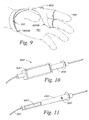
FIGS. 8A, 8B and 9 are illustrations of a remote display holder in the form of a glove according to an embodiment of the invention;
FIG. 10 is an illustration of a lead coupled to a remote display according to an embodiment of the invention;
FIG. 11 is an illustration of a lead incorporating a remote display according to an embodiment of the invention; and
FIG. 12 is an illustration of a method according to an embodiment of the invention.
DETAILED DESCRIPTION
A system 100 for obtaining electrical measurements is illustrated by way of example in FIG. 1. A remote display 400 is provided for use with a portable meter 200. The portable meter 200 may be similar to any of a wide variety of portable meters, such as a multimeter capable of obtaining electrical measurements.
As used herein, the term “portable meter” is intended to include meters and test devices that are portable. Portable meters and test devices may be configured for handheld use and may optionally be placed on a desktop or test bench. Often, portable meters will be configured to be used with leads, although the invention is not so limited. Examples of portable meters include, but are not limited to, test devices to analyze data transmission on network cabling and/or multimeters. Examples of multimeters on which the portable meter 200 may be based include the FLUKE 189 Digital Multimeter from FLUKE Corporation of Everett, Washington, the True RMS Reading Multimeter, part number 93-105/00408, available from GREENLEE TEXTRON Inc. of Rockford Ill., the TEST BENCH Model 391A available from BK PRECISION of Yorba Linda, Calif. and the Handheld MULTISCOPE, part number 381265 available from EXTECH INSTRUMENTS Corporation of Waltham, Mass.
As also shown in FIG. 2, the portable meter 200 may optionally be provided with a display 210 and controls 220 to provide control inputs to operate the functions of the portable meter 200 and/or a remote display 400. Lead ports 230 may also be provided for attaching leads 300, as is typically done by the use of a lead wire 310 associated with each lead 300. A remote display interface port 240 is also provided for communication with the remote display 400.
The remote display 400 includes a display panel 430 and a communications port 410 for communication coupling with the remote display interface port 240 of the portable meter 200. Optionally, a remote display cable 412 may be used to couple the communications port 410 to the remote display interface port 240. As described in more detail herein, a control 420 may be provided on the remote display 400 to provide a control input for controlling a display mode of the remote display 400 and/or operation of the portable meter 200. Similarly, a control 320 may also be provided on a lead 300 for controlling a display mode of the remote display 400 and/or operation of the portable meter 200.
The system 100 may also include a portable meter holder 500 for mounting the portable meter 100 to a user. A remote display holder 600 may also be provided for mounting the remote display 400 to a user. According to one aspect of the invention, the remote display holder 600 is configured to mount the remote display 400 to an extremity 700 of a user, such as a wrist and/or hand.
With further reference to FIG. 2, the display 210 of the portable meter 200 is shown by way of example. A wide variety of displays are within the scope of the invention. The display 210 may be tailored for specific applications for which the portable meter 200 is intended. Furthermore, the display 210 may be omitted from the portable meter 200 entirely. The remote display 400 may be configured to be attachable to and detachable from the portable meter 200. In such a case, the remote display 400 could optionally be able to be located in the position of the display 210 of FIG. 2 when attached to the portable meter 200. The remote display 400 could be held in place by a hook and loop fastener, a latch, a clip, a snap, or other devices able to mount the remote display 400 to the portable meter 200. When removed from this position, the remote display 400 would provide the capability of remotely displaying information obtained from the portable meter.
The remote display interface port 240 may be configured to provide a wired connection to the remote display 400 by the use of a remote display cable 412, as illustrated in FIG. 1. Alternatively, the remote display interface port 240 may be configured to provide a wireless coupling for communication to the remote display 400. A wireless coupling may be formed in a wide variety of ways. Some examples of wireless couplings include infrared (IR) communications or other invisible or visible light signals as well as radio frequency (RF) signals, or other electromagnetic wavelength communications and other wireless coupling types known in the art for communication between electronic devices.
Providing display signals to the display 210 in the portable meter 200 is conventional. According to the invention, the remote display interface port 240 may be configured to provide the same display signals to the remote display 400 that are provided to the display 210 of the portable meter 200. Alternatively, the portable meter 200 may be configured to enable different information and/or display signals to be provided to the remote display interface port 240 for use by the remote display 400. In the event the display 210 is omitted from the portable meter 200, the display signals that would typically be provided to the display 210 could be provided to the remote display interface port 240 for use by the remote display 400.
The remote display interface port 240 may also be configured to send and/or receive information relating to control inputs that may be activated by controls on the portable meter 200, the remote display 400 and/or a lead 300. The one or more lead ports 230 may also be configured to send and/or receive information relating to control inputs that may be activated by controls on one or more leads 300. It is understood that the controls 220 may be omitted from the portable meter 200, as optional controls on the remote display 400 and/or leads 300 may be used to control the portable meter 200.
The lead 300 may be any of a wide variety of leads known in the art. Examples include probe leads, alligator-clip leads, and leads that can be used to obtain other measurements. Examples include leads for measuring temperature, radio frequency (RF) signals and luminance.
The portable meter holder 500 may be provided to mount the portable meter 200 to a user. Examples of portable meter holders 500 include belt loops, belt clips, shoulder straps, or other devices known in the art for mounting a device to a user. The portable meter holder 500 may include the use of an adhesive or strapping or other fastening devices, such as hook and loop fasteners, such as fasteners available from VELCRO Corporation to secure the portable meter 200. In the case of the remote display 400 being attachable to the portable meter 200, the portable meter holder 500 may optionally use a similar fastening device as is used between the remote display 400 and portable meter 200. For example, a hook and loop fastener may be used in both cases, allowing a user to detach the remote display 400 from the portable meter 200 and attach the remote display 400 to the portable meter holder 500.
Various examples of remote displays 400 are shown in FIGS. 3-6. With reference to FIG. 3, a remote display 400A is illustrated having a display panel 430 accommodated within a case 440. A communications port 410 is provided for communication with the portable meter 200. As described above, the portable meter 200 and remote display 400 may communicate via a remote display cable 412 or via wireless coupling. It is understood that the communications port 410 would be configured for the appropriate type of communications with the portable meter 200. As such, the communications port 410 may be entirely internal to the remote display 400, such as for use with a wireless coupling.
The case 440 of the remote display 200 may be a rigid or flexible case, as appropriate for accommodating the display panel 430. The case 440 may encapsulate the display panel 430 or may be configured to extend along only a portion of the display panel 430. The case 440 is intended to provide a structural link between the communications port 410 and the display panel 430.
The display panel 430 may be formed of a wide variety of display types. For example, light emitting diodes or liquid crystal displays may be used, as well other display technologies known in the art, such as plasma displays. Other types of display panels may be apparent to one of skill in the art upon review of this description and are to be considered within the scope of the invention. The display panel 430 may be configured to display information obtained by the portable meter 200. The information may be displayed in a variety of forms, including by way of example, digital, analog and/or graphical. It is understood that a combination of one or more of various types of display formats may be used in simultaneous or sequential combination.
By way of example, FIG. 4 illustrates a remote display 400B having a digital display 214 in combination with unit indicators 212. It is understood that one or more of the unit indicators 212 may be displayed at any time, and that unit indicators for voltage, resistance and current are illustrated simultaneously in FIG. 4 for purposes of illustration.
The remote display 400B of FIG. 4 further illustrates a second communications port 411 that may be used in place of or in addition to the communications port 410. One, two, three or more communications ports may be provided at various locations on or within the remote display 400 for enabling a plurality of mounting options for the remote display 400.
The remote display 400B also illustrates a plurality of controls 420 that may be provided with the remote display 400 for controlling a display mode of the remote display 400 and/or controlling the operation of the portable meter 200 by way of the communication with the portable meter 200. The controls 420 may be any of a wide variety of input devices. Examples include, but are not limited to, a button, a switch, a touch screen, a dial, a knob, a keypad, a joystick and/or a microphone. The microphone may be configured to recognize different sound levels or be equipped with a voice recognition capability. It is understood that the remote display may be provided with any combination of one or more controls 420, or may not be provided with a control 420. Also, the controls 420 are not limited to a front surface of the remote display, and may be provided at any location on the remote display.
FIG. 5 illustrates a further example of a remote display 400C. The remote display 400C includes various features of the example remote displays 400 of FIGS. 3 and 4, while adding a lead port 450. The lead port 450 enables a user to couple a lead 300 directly to the remote display 400. Such a configuration allows for the coupling between the remote display 400 and portable meter 200 to serve as the communications path for the lead 300 and the portable meter 200. Such an arrangement may reduce the number of wires to be managed by a user and/or may shorten the length of wires, because a short lead wire 310 may be used for the lead 300 held by the user's extremity at which the remote display 400 is mounted. Whereas a longer lead wire 310 would be required if the lead wire 310 extended all the way back to the portable meter 200, which may, be mounted on the user's waist. One or more lead ports 450 may be mounted in any location on the remote display.
The remote display 400C of FIG. 5 also provides a further example of a display panel 430C in the form of a combination display. The display panel 430C shows an example of the simultaneous use of a digital display 214 with an analog display 216 in combination with a variety of unit indicators 212 and other status indicators 218, such as those indicating whether the portable meter 200 is in an auto-ranging mode or whether the portable meter 200 will emit audible signals and a battery status indicator for the portable meter 200. These illustrated examples are not limiting, and the invention can include a wide variety of indicators. The remote display 400C may also be provided with a light 470 to enhance viewing of the display panel 430C and/or controls 420 in low-light conditions. The light 470 may be a wide variety of lights, including direct illumination and back lights and others known in the art for illuminating a display panel.
FIG. 6 illustrates a further example of the remote display according to another embodiment of the invention. A remote display 400D is illustrated having the display 430C described above in relation to FIG. 5 and a case 440D that is configured for wireless communication with the portable meter 200. The remote display 400D of FIG. 5 is provided with an optional glare shield 460 that may be fixedly mounted or removably mounted to the case 440D to aid in reducing glare on the display panel 430C.
It is understood that the various features of the remote displays 400 of FIGS. 3-6 may be used in combination and are illustrated by way of example only. The invention is not limited to these examples, and a wide variety of alternatives are within the scope of the invention.
The remote display 400 may optionally be mounted to a user. Various embodiments of remote display holders 600 are shown in FIGS. 7-11. With reference to FIG. 7, a remote display holder 600A is shown in the form of a wristband to which a remote display 400 is mounted. The wristband is illustrated on an extremity 700 of a user. The remote display 400 may be coupled with the remote display holder 600A by the use of an adhesive, a hook and loop fastener and/or stitching of material. The material may be material forming the remote display holder 600 and/or material encasing or surrounding a portion of the remote display 400 and mated to or forming a part of the remote display holder 600. The remote display holder 600 may be formed of a wide variety of materials including various fabrics, leathers, plastics, rubbers or other items. Examples include materials typically used in the construction of wristbands and gloves known in the art.
With reference to FIGS. 8A, 8B and 9, a remote display holder 600B is provided in the form of a glove. As illustrated by way of example in FIGS. 8A, 8B and 9, the remote display holder 600B is formed as an open-palm glove arranged to be coupled to a wrist 710 of a user and at least one finger 720 of a user. Coupled to the remote display 600 is a remote display 400. The remote display 400 may be coupled to the remote display holder 600B of FIGS. 8A, 8B and 9 in a wide variety of ways; such as the examples discussed above in relation to the remote display holder 600A of FIG. 7.
The remote display holder 600B in the form of a glove may provide a variety of mounting positions for the remote display 400. In order to enable the remote display 400 to be positioned for correct orientation within the view of a user. For example, the remote display 400 may be configured to include a remote display cable 412 connected to the communications port 410 to locate the remote display 400 proximate to a thumb and a back of the hand of the user. One example of such a location of the remote display 400 is to longitudinally orient the remote display 400 between a user's wrist 710 and forefinger 720, as shown in FIG. 8A. This arrangement may be desirable if the user is working to obtain measurements at or below an eye-level of the user. In another example, as shown in FIG. 8B, the remote display 400 may be configured with the remote display cable 412 coupled to the second communication port 411. In such a case, the remote display 400 may be located transversely between a user's wrist 710 and forefinger 720. Such a configuration may be more suitable to obtaining measurements above an eye-level of the user, as the remote display 400 may then be more easily read by the user. It is understood that a communication port 410 may be located at an opposite end of the remote display 400 in addition to or in place of the illustrated communication ports. By locating a communication port at an opposite end of the remote display 400, the remote display 400 may be easily configured for use on another hand of the user by the use of an appropriate remote display holder 600, such as a glove formed for a right hand. It is understood that a wireless coupling may be used between the remote display 400 and portable meter 200.
The remote display holders 600 illustrated in FIGS. 7-9 may be provided to conveniently locate a remote display 400, while allowing a user to manipulate one or more leads 300. The remote display holder 600B of FIGS. 8A, 8B and 9 is configured to be secured about a user's wrist 710 and at least one finger 720, while not encasing the finger 720, thereby retaining the user's ability to touch the lead and/or other objects without interference from the remote display holder 600B. It is understood that the invention is not so limited and any form of glove may be used in combination with the remote display 400, including gloves fully enclosing a user's hand and/or not coupled to a user's wrist.
Examples of leads 300 are provided in FIGS. 10 and 11. FIG. 10 illustrates a lead 300 also operating as a remote display holder 600. Specifically, a remote display 400 is coupled to the lead 300 in any of a variety of ways, such as examples described above in relation to other remote display holders. The coupling may be configured to allow the remote display 400 to be removable from the lead 300. Alternatively, the remote display 400 may be fixedly secured to the lead 300.
It is understood that a wide variety of leads are within the scope of the invention. Any leads known in the art for use with portable meters are within the scope of the invention. Leads 300 may or may not operate as a remote display holder 600.
As illustrated in FIG. 11, a remote display 400 may be incorporated within the lead 300. In such a configuration, the lead 300 may optionally serve as a case for the display panel of the remote display 400. The embodiment of FIG. 11 further illustrates a control 320 provided on the lead 300. As discussed above in relation to the controls 420 of the remote display 400, the control 320 may be used to control a display mode of the remote display 400 and/or various functions of the portable meter 200. In the embodiment of FIG. 11, a remote display cable may be configured within the lead wire 310 and/or a wireless coupling to the portable meter 200 may be used. It is understood that a plurality of controls 320 may be provided on the lead 300.
As shown in FIG. 12, a further embodiment of the invention is provided in the form of a method 800 for configuring a remote display coupled to a portable meter. The method includes a step 810 of mounting a remote display to an extremity of a user by the use of a remote display holder. The remote display is coupled, step 829, to a portable meter. Optionally, the method 800 may include the step 830 of mounting the portable meter to a user by the use of a meter holder. The method 800 may also optionally include the step of locating, step 840, a lead in the hand of a user. Also, a first and second lead may be electrically coupled, step 850, to an electrical apparatus. A reading may be obtained, step 860, on the portable meter. The reading is representative of a characteristic of the electrical apparatus that is sampled by the first and second leads. Information may then be viewed, step 870, on the remote display that corresponds to the reading obtained on the meter, step 860. The viewing step, step 870, may involve the reading being representative of an electrical measurement and the information viewed on the remote display corresponding to voltage, resistance and/or current.
The method 800 may also include the optional step of selecting, step 880, a mode of the remote display by activating a control. The control may be located on a lead, the remote display and/or the portable meter.
The method 800 may also optionally include the step of inputting, step 890, a command to the portable meter by activating a control on the remote display.
The method 800 may include a wide variety of variations, such as the examples described herein in relation to other embodiments of the invention. For example, the mounting of a remote display to an extremity of a user may involve inserting a hand of a user into an open palm glove extending to at least one finger of the hand. By way of further example, the step of mounting the remote display to the extremity of the user may include coupling the remote display holder to at least a wrist of the user. The remote display may also be located proximate to a thumb and a back of a hand of a user. A further example of a variation of the method 800 includes coupling the remote display to the portable meter by the use of at least one wire and/or by the use of a wireless coupling. Optionally, the coupling of the remote display to the portable meter may include selecting from a plurality of ports on the remote display to couple the at least one wire to the remote display.
A wide variety of display modes and functions may be activated by a control. By way of example, various display ranges and an auto-range function may be activated. The portable meter 200 may be instructed to emit audible signals, such as upon the completion of obtaining an electrical measurement. Other portable meter functions include selecting the type of electrical measurement to be made, such as for example voltage, resistance or current measurements. Examples of input commands that may be received by the control include powering on or off the portable meter 200 and/or the remote display 400. Furthermore, illumination for the display panel 430 of the remote display 400 may be activated or deactivated.
The present invention has been described by way of example, and modifications and variations of the described embodiments will suggest themselves to skilled artisans in this field without departing from the spirit of the invention. Aspects and characteristics of the above-described embodiments may be used in combination. For example, the system 100 for obtaining electrical measurements may include any of the additional features described herein in relation to the various components of the system 100 such as the various remote display holders and remote displays and variations thereof. The described embodiments are merely illustrative and should not be considered restrictive in any way. The scope of the invention is to be measured by the appended claims, rather than the preceding description, and all variations and equivalents that fall within the range of the claims are intended to be embraced therein.

Claims (58)

1. A remote display for a portable meter capable of obtaining an electrical measurement, comprising:
a display panel configured to remotely display information obtained from said portable meter;
a case accommodating said display panel;
a first port coupled to said display panel and configured to receive data corresponding to said information from said portable meter;
a control for said portable meter coupled to said first port to enable a control input for said portable meter to select a mode of said remote display; and
a second port located apart from said first port configured to receive data from said portable meter.
2. The remoto display of claim 1, wherein said display panel is a liquid crystal display having at least one unit indicator specific to an electrical measurement unit and incorporated into the liquid crystal display.
3. The remote display of claim 2, wherein said unit indicator is specific to an electrical in measurement unit selected from the group of volts and ohms.
4. The remote display of claim 1, wherein said electrical measurement is at least one of the group of voltage, resistance and current.
5. The remote display of claim 1, wherein said first port is configured to receive at least one wire.
6. The remote display of claim 1 wherein said first port is configured to communicate with said portable meter without the use of wires coupling said first port to said portable meter.
7. The remote display of claim 1, further comprising a lead port coupled to said case and in communication with said first port to enable a lead for use with said portable meter to be coupled to said portable meter through said remote display.
8. The remote display of claim 1, further comprising a light positioned to illuminate said display panel.
9. The remote display of claim 1, further comprising a glare shield mounted to said case and positioned to inhibit light from striking said display panel.
10. The remote display of claim 1, wherein said case is integral with a lead for use with said portable meter.
11. The remote display of claim 1, wherein said display panel displays said information digitally.
12. A remote viewing apparatus for use with a portable meter capable of obtaining an electrical measurement, comprising:
a remote display to display said electrical measurement obtained by said portable meter; and
a remote display holder coupled to said remote display and to mount said remote display to an arm or hand of a user;
wherein said remote display holder is formed as a glove and said remote display is mounted to said glove by least by a hook and loop fastener.
13. The remote viewing apparatus of claim 12, wherein said remote display comprises:
a display panel configured to remotely display information obtained from said portable meter;
a case accommodating said display panel; and
a first port coupled to said display panel and configured to receive data corresponding to said information from said portable meter.
14. The remote viewing apparatus of claim 13, wherein said display panel is a liquid crystal display having at least one unit indicator specific to an electrical measurement unit and incorporated into the liquid crystal display.
15. The remote viewing apparatus of claim 14, wherein said unit indicator is specific to an electrical measurement unit selected from the group of volts and ohms.
16. The remote viewing apparatus of claim 13, further comprising a second port located apart from said first port configured to receive data from said portable meter.
17. The remote viewing apparatus of claim 13, further comprising a control for said portable meter, mounted to said remote display and coupled to said port to enable a control input for said portable meter to be entered by a user at said remote display and provided through said first port.
18. The remote viewing apparatus of claim 12, wherein said remote display holder is to mount to an extremity of said user.
19. The remote viewing apparatus of claim 12, wherein said remote display holder to mount to at least a wrist of a user.
20. The remote viewing apparatus of claim 12, wherein said remote display holder to mount to a hand of a user to lo ate said remote display proximate to a thumb and back of said hand of said user.
21. The remote viewing apparatus of claim 12, wherein said glove is formed as an open-palm glove.
22. The remote viewing apparatus of claim 21, wherein said glove does not encase any fingers.
23. The remote viewing apparatus of claim 12, wherein said remote display is mounted to said glove by at least by stitching.
24. A system for obtaining electrical measurements, comprising:
a portable meter capable of obtaining an electrical measurement;
a remote display, remotely located from said portable meter, coupled to said portable meter and capable of displaying information obtained by said portable meter; and
a remote display holder in the form of a glove, coupled to said remote display and adapted to mount to an extremity of a user.
25. The system of claim 24, wherein said remote display holder is adapted to mount to at least a wrist of a user.
26. The system of claim 24, wherein said remote display holder is adapted to mount to a hand of a user to locate said remote display proximate to a thumb and a back of said hand of said user.
27. The system of claim 24, wherein said remote display holder further comprises a hook and loop fastener coupling said remote display to said glove.
28. The system of claim 24, further comprising a meter holder coupled to said portable meter and adapted to enable said portable meter to be mounted to a user.
29. The system of claim 24, further comprising at least one lead for use with said portable meter.
30. The system of claim 29, further comprising a control on said lead to send a control input to said portable meter.
31. The system of claim 29, wherein said remote display is integral with said lead.
32. The system of claim 29, further comprising control on said lead for selecting a mode of said remote display.
33. The system of claim 29, further comprising a lead port coupled to said remote display and in communication with said portable meter to enable a lead for use with said portable meter to be coupled to said portable meter through said remote display.
34. The system of claim 33 further comprising a control on said portable meter for selecting a mode of said remote display.
35. The system of claim 24, further comprising control on said remote display for selecting a mod of said remote display.
36. The system of claim 24, wherein said remote display comprises:
a display panel configured to remotely display information obtained from said portable meter;
a case accommodating said display panel; and
a first port coupled to said display panel and configured to receive data corresponding to said information from said portable meter.
37. The system of claim 36, wherein said display panel displays said information digitally.
38. The system of claim 24, further comprising a control for said portable meter coupled to said port to enable a control input for said meter to be entered by a user at said remote display and provided through said port.
39. The system of claim 24, wherein said coupling of said remote display to said portable meter is performed by at least one wire.
40. The system of claim 24, wherein said coupling of said remote display to said portable meter is performed by a wireless coupling.
41. The system of claim 24, wherein said remote display is attachable and detachable from said portable meter.
42. A method of configuring a remote display coupled to a portable meter, said method comprising the steps of:
mounting a remote display to an extremity of a user by he us of a remote display holder; and
coupling said remote display to said portable meter;
wherein said step of mounting a remote display to an extremity of a user includes locating said remote display proximate to a thumb and a back of a hand of said user.
43. The method of claim 42, further comprising the step of mounting said portable meter to a user by the use of meter holder.
44. The method of claim 42, further comprising the step of locating a first lead in a hand of said user.
45. The method of claim 44, further comprising the steps of:
electrically coupling said first lead and a second lead to an electrical apparatus;
obtaining a reading on said portable meter representative of a characteristic of said electrical apparatus sampled by said first lead and said second lead; and
viewing information corresponding to said reading on said remote display.
46. The remote display of claim 45, wherein said step of viewing involves said reading being representative of an electrical measurement and said information is a value corresponding to at least one of the group of voltage, resistance and current.
47. The method of claim 45, further comprising the step of selecting a mode of said remote display by activating control on said at least one lead.
48. The method of claim 45, further comprising the step of selecting a mode of said remote display by activating a control on said remote display.
49. The method of claim 45, further comprising the step of selecting a mode of said remote display by activating a control on said portable meter.
50. The method of claim 42, further comprising the step of inputting a command to said portable meter by activating a control on said remote display.
51. The method of claim 42, wherein said step of mounting a remote display to an extremity of a user includes inserting a hand of said user into an open-palm glove extending to at least one finger of said hand.
52. The method of claim 42, wherein said step of mounting a remote display to an extremity of a user includes coupling said remote display holder to at least a wrist of said user.
53. The method of claim 42, wherein said coupling step includes coupling said remote display to said portable meter by the use of at least one wire.
54. The method o claim 53, wherein said coupling step includes selecting from a plurality of ports on said remote display to couple said at least one wire to said remote display.
55. The method of claim 42, wherein said coupling step includes coupling said remote display to said portable meter by the use of a wireless coupling.
56. The method of claim 42, further comprising, before said mounting step, the step of detaching said remote display from said portable meter.
57. A remote viewing apparatus for use with a portable meter capable of obtaining an electrical measurement comprising:
a remote display to display said electrical measurement obtained by said portable meter; and
a remote display holder coupled to said remote display and to mount said remote display to an arm or hand of a user;
wherein said remote display holder to mount to at least a wrist of a user.
58. A method of configuring a remote display coupled to a portable meter, said method comprising the steps of:
mounting a remote display to an extremity of a user by the use of a remote display holder; and
coupling said remote display to said portable meter;
wherein said coupling step includes coupling said remote display to said portable meter by the use of a wireless coupling.
US10/368,040 2003-02-14 2003-02-14 Remote display for portable meter Active 2024-06-07 US7304618B2 (en)

Priority Applications (2)

Application Number Priority Date Filing Date Title
US10/368,040 US7304618B2 (en) 2003-02-14 2003-02-14 Remote display for portable meter
PCT/US2004/004368 WO2004075150A2 (en) 2003-02-14 2004-02-13 Remote display for portable meter

Applications Claiming Priority (1)

Application Number Priority Date Filing Date Title
US10/368,040 US7304618B2 (en) 2003-02-14 2003-02-14 Remote display for portable meter

Publications (2)

Publication Number Publication Date
US20040160410A1 US20040160410A1 (en) 2004-08-19
US7304618B2 true US7304618B2 (en) 2007-12-04

Family

ID=32850078

Family Applications (1)

Application Number Title Priority Date Filing Date
US10/368,040 Active 2024-06-07 US7304618B2 (en) 2003-02-14 2003-02-14 Remote display for portable meter

Country Status (2)

Country Link
US (1) US7304618B2 (en)
WO (1) WO2004075150A2 (en)

Cited By (22)

* Cited by examiner, † Cited by third party
Publication number Priority date Publication date Assignee Title
US20070008239A1 (en) * 2005-07-08 2007-01-11 Microsoft Corporation Communications device interactive display
US20080143317A1 (en) * 2006-12-19 2008-06-19 Lecroy Corporation Resizable display
US20080231256A1 (en) * 2006-12-19 2008-09-25 Lecroy Corporation Removable Front Panel Control for Oscilloscope
US20080278143A1 (en) * 2006-12-19 2008-11-13 Lecroy Corporation Remote Display and Control for Test and Measurement Apparatus
US7557559B1 (en) * 2006-06-19 2009-07-07 Seektech, Inc. Compact line illuminator for locating buried pipes and cables
US7746051B1 (en) 2009-02-18 2010-06-29 Hd Electric Company Voltmeter with dual displays
US20100181990A1 (en) * 2009-01-21 2010-07-22 Fluke Corporation Digital multimeter having remote display with automatic communication mode switching
EP2299283A1 (en) 2009-09-18 2011-03-23 Fluke Corporation Digital multimeter having remote display with automatic communication binding
US20110074395A1 (en) * 2009-09-28 2011-03-31 Fluke Corporation Digital multimeters including a remote display
US20110193548A1 (en) * 2010-02-05 2011-08-11 Appa Technology Corp. Separation-type avometer
US20110316523A1 (en) * 2010-06-29 2011-12-29 Hsin-Chen Ko Avometer
US20130093449A1 (en) * 2011-10-12 2013-04-18 Fluke Corporation Voltage tester having alternatively attachable or separable probes
US20140267296A1 (en) * 2013-03-15 2014-09-18 Fluke Corporation Automated Combined Display of Measurement Data
EP2910963A1 (en) 2014-02-21 2015-08-26 Danaher (Shanghai) Industrial Instrumentation Technologies R&D Co Ltd Methods and instruments for testing batteries
USD738242S1 (en) 2013-12-31 2015-09-08 Milwaukee Electric Tool Corporation Electrical tester
US9664708B2 (en) 2014-01-09 2017-05-30 Milwaukee Electric Tool Corporation Test and measurement device including grooves for receiving probes in a use position
US9726715B2 (en) 2011-08-03 2017-08-08 Fluke Corporation Maintenance management systems and methods
US9736342B2 (en) 2012-10-19 2017-08-15 Milwaukee Electric Tool Corporation Visual inspection device
US9739801B2 (en) 2013-07-16 2017-08-22 Fluke Corporation Analytical gateway device for measurement devices
US9766270B2 (en) 2013-12-30 2017-09-19 Fluke Corporation Wireless test measurement
US10095659B2 (en) 2012-08-03 2018-10-09 Fluke Corporation Handheld devices, systems, and methods for measuring parameters
USD852072S1 (en) * 2017-09-01 2019-06-25 Fluke Corporation Proving unit for use with electrical test tools

Families Citing this family (20)

* Cited by examiner, † Cited by third party
Publication number Priority date Publication date Assignee Title
GB0413746D0 (en) * 2004-06-19 2004-07-21 Atomic Energy Authority Uk Wireless probe
US20080229226A1 (en) * 2007-03-09 2008-09-18 Lutron Electronics Co., Inc. System and method for graphically displaying energy consumption and savings
DE102008036860A1 (en) * 2008-08-07 2010-02-25 Ika-Werke Gmbh & Co. Kg Laboratory unit with a laboratory device and a remote control
US8004272B2 (en) * 2009-03-11 2011-08-23 Fluke Corporation Digital multimeter having visible light communication port
CN101895596A (en) * 2009-05-20 2010-11-24 深圳富泰宏精密工业有限公司 Multifunctional portable electronic device
US8856555B2 (en) * 2009-07-17 2014-10-07 Fluke Corporation Power state coordination for portable test tools
CN102095906A (en) * 2009-12-11 2011-06-15 瑞星科技股份有限公司 Separated ammeter
US8854321B2 (en) * 2011-05-02 2014-10-07 Verizon Patent And Licensing Inc. Methods and systems for facilitating data entry by way of a touch screen
ITBO20120157A1 (en) * 2012-03-22 2013-09-23 Ht Italia S R L MEASUREMENT GROUP OF ENVIRONMENTAL PARAMETERS, MECHANICAL, ELECTRIC AND SIMILAR QUANTITIES.
JP2013213693A (en) * 2012-03-30 2013-10-17 Hioki Ee Corp Measurement device
CN103675359B (en) * 2012-09-11 2018-06-08 福禄克精密测量有限公司 Wireless controller for cell tester and the cell tester component comprising the handle
JP6054126B2 (en) * 2012-10-05 2016-12-27 日置電機株式会社 measuring device
FR3019301B1 (en) * 2014-03-25 2018-02-09 Societe Anonyme Des Ets Catu ELECTRIC MEASURING AND CONTROL APPARATUS
JP2016095187A (en) * 2014-11-13 2016-05-26 中国電力株式会社 Electric tester
US11789040B2 (en) 2018-03-13 2023-10-17 Rohde & Schwarz Gmbh & Co. Kg Measurement system and method of operating a measurement system
EP3540446B1 (en) 2018-03-13 2021-09-29 Rohde & Schwarz GmbH & Co. KG Measurement system and method for operating a measurement system
CN112534275A (en) * 2018-06-11 2021-03-19 特克特朗尼克公司 Test and measurement probe with touch screen
FR3092230B1 (en) * 2019-02-06 2021-02-12 Neoratech Device for checking the absence of voltage in an electrical circuit
IT201900022941A1 (en) * 2019-12-10 2021-06-10 Matera Inerti S R L Intelligent device and method for monitoring concrete via the Internet of Things
DE102020108528A1 (en) * 2020-03-27 2021-09-30 GMC-I Messtechnik GmbH Measuring device arrangement comprising a measuring device device for measuring electrical measured variables

Citations (20)

* Cited by examiner, † Cited by third party
Publication number Priority date Publication date Assignee Title
US3938207A (en) * 1973-10-25 1976-02-17 Gary Clyde Drescher Swimmer's glove having joints bendable only in closing direction of the hand
US4949274A (en) 1987-05-22 1990-08-14 Omega Engineering, Inc. Test meters
US5008661A (en) 1985-09-27 1991-04-16 Raj Phani K Electronic remote chemical identification system
US5072174A (en) 1988-12-21 1991-12-10 Weber Hans R Measurement configuration comprising at least one electronic linear measuring probe
US5153511A (en) * 1991-12-13 1992-10-06 Lee Chung Cheng Test lead socket indicating device for a volt-ohm-milliameter
EP0318549B1 (en) 1987-05-22 1993-03-31 Omega Engineering, Inc. Test meters
US5420739A (en) * 1992-12-16 1995-05-30 Smk Corporation Portable audio device with a detachable control unit
US5503145A (en) * 1992-06-19 1996-04-02 Clough; Stuart Computer-controlling life support system and method for mixed-gas diving
US5514861A (en) * 1988-05-11 1996-05-07 Symbol Technologies, Inc. Computer and/or scanner system mounted on a glove
US5602744A (en) 1994-09-29 1997-02-11 Meek; Jean L. Universal send/receive utility usage data gathering system
US5640155A (en) 1992-02-18 1997-06-17 O'connor Springer Meter cradle with wireless communication port
US6095682A (en) 1997-11-21 2000-08-01 Omega Engineering, Inc. Pyrometer multimeter
US6098886A (en) * 1998-01-21 2000-08-08 Symbol Technologies, Inc. Glove-mounted system for reading bar code symbols
US6151208A (en) * 1998-06-24 2000-11-21 Digital Equipment Corporation Wearable computing device mounted on superior dorsal aspect of a hand
US6330092B1 (en) * 1998-05-08 2001-12-11 Agilent Technologies, Inc. Polarization based differential receiver for reduction of background in free-space optical links
US6384591B1 (en) * 1997-09-11 2002-05-07 Comsonics, Inc. Hands-free signal level meter
US6445175B1 (en) 1997-09-11 2002-09-03 Comsonics, Inc. Remote, wireless electrical signal measurement device
US20020149384A1 (en) * 2001-04-11 2002-10-17 Reasoner Kelly J. Test probe including control device
US6525819B1 (en) * 1998-09-02 2003-02-25 Pocketspec Technologies Inc. Colorimeter for dental applications
US20030137310A1 (en) * 2002-01-22 2003-07-24 Thomas Holzel Remote viewing screen for test instrument

Family Cites Families (1)

* Cited by examiner, † Cited by third party
Publication number Priority date Publication date Assignee Title
US6539459B1 (en) * 1998-08-24 2003-03-25 Sony Corporation Library device, operating mode setting method therefor

Patent Citations (20)

* Cited by examiner, † Cited by third party
Publication number Priority date Publication date Assignee Title
US3938207A (en) * 1973-10-25 1976-02-17 Gary Clyde Drescher Swimmer's glove having joints bendable only in closing direction of the hand
US5008661A (en) 1985-09-27 1991-04-16 Raj Phani K Electronic remote chemical identification system
US4949274A (en) 1987-05-22 1990-08-14 Omega Engineering, Inc. Test meters
EP0318549B1 (en) 1987-05-22 1993-03-31 Omega Engineering, Inc. Test meters
US5514861A (en) * 1988-05-11 1996-05-07 Symbol Technologies, Inc. Computer and/or scanner system mounted on a glove
US5072174A (en) 1988-12-21 1991-12-10 Weber Hans R Measurement configuration comprising at least one electronic linear measuring probe
US5153511A (en) * 1991-12-13 1992-10-06 Lee Chung Cheng Test lead socket indicating device for a volt-ohm-milliameter
US5640155A (en) 1992-02-18 1997-06-17 O'connor Springer Meter cradle with wireless communication port
US5503145A (en) * 1992-06-19 1996-04-02 Clough; Stuart Computer-controlling life support system and method for mixed-gas diving
US5420739A (en) * 1992-12-16 1995-05-30 Smk Corporation Portable audio device with a detachable control unit
US5602744A (en) 1994-09-29 1997-02-11 Meek; Jean L. Universal send/receive utility usage data gathering system
US6384591B1 (en) * 1997-09-11 2002-05-07 Comsonics, Inc. Hands-free signal level meter
US6445175B1 (en) 1997-09-11 2002-09-03 Comsonics, Inc. Remote, wireless electrical signal measurement device
US6095682A (en) 1997-11-21 2000-08-01 Omega Engineering, Inc. Pyrometer multimeter
US6098886A (en) * 1998-01-21 2000-08-08 Symbol Technologies, Inc. Glove-mounted system for reading bar code symbols
US6330092B1 (en) * 1998-05-08 2001-12-11 Agilent Technologies, Inc. Polarization based differential receiver for reduction of background in free-space optical links
US6151208A (en) * 1998-06-24 2000-11-21 Digital Equipment Corporation Wearable computing device mounted on superior dorsal aspect of a hand
US6525819B1 (en) * 1998-09-02 2003-02-25 Pocketspec Technologies Inc. Colorimeter for dental applications
US20020149384A1 (en) * 2001-04-11 2002-10-17 Reasoner Kelly J. Test probe including control device
US20030137310A1 (en) * 2002-01-22 2003-07-24 Thomas Holzel Remote viewing screen for test instrument

Cited By (45)

* Cited by examiner, † Cited by third party
Publication number Priority date Publication date Assignee Title
US20070008239A1 (en) * 2005-07-08 2007-01-11 Microsoft Corporation Communications device interactive display
US7557559B1 (en) * 2006-06-19 2009-07-07 Seektech, Inc. Compact line illuminator for locating buried pipes and cables
US20080143317A1 (en) * 2006-12-19 2008-06-19 Lecroy Corporation Resizable display
US20080231256A1 (en) * 2006-12-19 2008-09-25 Lecroy Corporation Removable Front Panel Control for Oscilloscope
US20080278143A1 (en) * 2006-12-19 2008-11-13 Lecroy Corporation Remote Display and Control for Test and Measurement Apparatus
US8358121B2 (en) * 2009-01-21 2013-01-22 Fluke Corporation Digital multimeter having remote display with automatic communication mode switching
US20100181990A1 (en) * 2009-01-21 2010-07-22 Fluke Corporation Digital multimeter having remote display with automatic communication mode switching
EP2211189A2 (en) 2009-01-21 2010-07-28 Fluke Corporation Digital multimeter having remote display with automatic communication mode switching
US7746051B1 (en) 2009-02-18 2010-06-29 Hd Electric Company Voltmeter with dual displays
US9008517B2 (en) 2009-09-18 2015-04-14 Fluke Corporation Digital multimeter having remote display with automatic communication binding
TWI426276B (en) * 2009-09-18 2014-02-11 Fluke Corp Digital multimeter having remote display with automatic communication binding
CN102023247A (en) * 2009-09-18 2011-04-20 弗卢克公司 Digital multimeter having remote display with automatic communication binding
US20150215985A1 (en) * 2009-09-18 2015-07-30 Fluke Corporation Digital multimeter having remote display with automatic communication binding
EP2299283A1 (en) 2009-09-18 2011-03-23 Fluke Corporation Digital multimeter having remote display with automatic communication binding
US8374507B2 (en) * 2009-09-18 2013-02-12 Fluke Corporation Digital multimeter having remote display with automatic communication binding
US20110069961A1 (en) * 2009-09-18 2011-03-24 Hudson Jeffrey C Digital multimeter having remote display with automatic communication binding
US8405380B2 (en) * 2009-09-28 2013-03-26 Fluke Corporation Digital multimeters including a remote display
US20110074395A1 (en) * 2009-09-28 2011-03-31 Fluke Corporation Digital multimeters including a remote display
US8803507B2 (en) 2009-09-28 2014-08-12 Fluke Corporation Digital multimeters including a remote display
CN102033150A (en) * 2009-09-28 2011-04-27 福禄克公司 Digital multimeter including a remote display
US20110193548A1 (en) * 2010-02-05 2011-08-11 Appa Technology Corp. Separation-type avometer
US20110316523A1 (en) * 2010-06-29 2011-12-29 Hsin-Chen Ko Avometer
US10725095B2 (en) 2011-08-03 2020-07-28 Fluke Corporation Maintenance management systems and methods
US9726715B2 (en) 2011-08-03 2017-08-08 Fluke Corporation Maintenance management systems and methods
US9423417B2 (en) * 2011-10-12 2016-08-23 Fluke Corporation Voltage tester having alternatively attachable or separable probes
US20130093449A1 (en) * 2011-10-12 2013-04-18 Fluke Corporation Voltage tester having alternatively attachable or separable probes
US10095659B2 (en) 2012-08-03 2018-10-09 Fluke Corporation Handheld devices, systems, and methods for measuring parameters
US9736342B2 (en) 2012-10-19 2017-08-15 Milwaukee Electric Tool Corporation Visual inspection device
US11082589B2 (en) 2012-10-19 2021-08-03 Milwaukee Electric Tool Corporation Visual inspection device
US10477079B2 (en) 2012-10-19 2019-11-12 Milwaukee Electric Tool Corporation Visual inspection device
US10788401B2 (en) 2013-03-15 2020-09-29 Fluke Corporation Remote sharing of measurement data
US10088389B2 (en) 2013-03-15 2018-10-02 Fluke Corporation Automatic recording and graphing of measurement data
US20140267296A1 (en) * 2013-03-15 2014-09-18 Fluke Corporation Automated Combined Display of Measurement Data
US11843904B2 (en) * 2013-03-15 2023-12-12 Fluke Corporation Automated combined display of measurement data
US10337962B2 (en) 2013-03-15 2019-07-02 Fluke Corporation Visible audiovisual annotation of infrared images using a separate wireless mobile device
US11641536B2 (en) 2013-03-15 2023-05-02 Fluke Corporation Capture and association of measurement data
US10809159B2 (en) * 2013-03-15 2020-10-20 Fluke Corporation Automated combined display of measurement data
US9541472B2 (en) 2013-03-15 2017-01-10 Fluke Corporation Unified data collection and reporting interface for equipment
US9739801B2 (en) 2013-07-16 2017-08-22 Fluke Corporation Analytical gateway device for measurement devices
US9766270B2 (en) 2013-12-30 2017-09-19 Fluke Corporation Wireless test measurement
USD738242S1 (en) 2013-12-31 2015-09-08 Milwaukee Electric Tool Corporation Electrical tester
US9664708B2 (en) 2014-01-09 2017-05-30 Milwaukee Electric Tool Corporation Test and measurement device including grooves for receiving probes in a use position
EP2910963A1 (en) 2014-02-21 2015-08-26 Danaher (Shanghai) Industrial Instrumentation Technologies R&D Co Ltd Methods and instruments for testing batteries
US10393815B2 (en) 2014-02-21 2019-08-27 Fluke Precision Measurement Ltd. Voice counting of each battery under test
USD852072S1 (en) * 2017-09-01 2019-06-25 Fluke Corporation Proving unit for use with electrical test tools

Also Published As

Publication number Publication date
WO2004075150A2 (en) 2004-09-02
US20040160410A1 (en) 2004-08-19
WO2004075150A3 (en) 2005-05-12

Similar Documents

Publication Publication Date Title
US7304618B2 (en) Remote display for portable meter
US7109700B2 (en) Multimeter having off-device display device and selection device
JP5039778B2 (en) Electrical measuring instrument with detachable current clamp
US9778285B2 (en) Electrical sensor systems and methods
EP2302401A1 (en) Digital multimeter including a remote display
US20020169361A1 (en) Endoscope shape detector
US20030137310A1 (en) Remote viewing screen for test instrument
US20070241740A1 (en) Hand-Held Probe
CN110998351A (en) Mobile instrument error testing device
JP2018514256A (en) Wearable device configured to support a measurement and transmission device
KR20020079549A (en) Test probe including control device
US20170172232A1 (en) Multimeter integrated with a glove
US7999818B2 (en) Hands-free, user-formatted instruction display system
CN208892571U (en) Electronic sphygmomanometer
US20050088168A1 (en) Control module for use with a test probe
CN211718351U (en) Probe of testing instrument and testing instrument
CN219348002U (en) Plug-in pit temperature detection device
EP2270519B1 (en) Multimeter
US11874963B2 (en) Multifunctional finger-activated device
US20230152348A1 (en) Measuring instrument assembly comprising a measuring instrument apparatus for measuring electrical measurement variables
KR101468110B1 (en) Multimeter by wearing on wrist
JPH10340133A (en) Electronic equipment having removable operation part and display part

Legal Events

Date Code Title Description
STCF Information on status: patent grant

Free format text: PATENTED CASE

FEPP Fee payment procedure

Free format text: PAYER NUMBER DE-ASSIGNED (ORIGINAL EVENT CODE: RMPN); ENTITY STATUS OF PATENT OWNER: LARGE ENTITY

Free format text: PAYOR NUMBER ASSIGNED (ORIGINAL EVENT CODE: ASPN); ENTITY STATUS OF PATENT OWNER: LARGE ENTITY

CC Certificate of correction
AS Assignment

Owner name: FLUKE CORPORATION, WASHINGTON

Free format text: LICENSE;ASSIGNOR:PLATHE, HENRY J., MR.;REEL/FRAME:022694/0444

Effective date: 20090308

FEPP Fee payment procedure

Free format text: PAT HOLDER NO LONGER CLAIMS SMALL ENTITY STATUS, ENTITY STATUS SET TO UNDISCOUNTED (ORIGINAL EVENT CODE: STOL); ENTITY STATUS OF PATENT OWNER: LARGE ENTITY

FPAY Fee payment

Year of fee payment: 4

FPAY Fee payment

Year of fee payment: 8

MAFP Maintenance fee payment

Free format text: PAYMENT OF MAINTENANCE FEE, 12TH YEAR, LARGE ENTITY (ORIGINAL EVENT CODE: M1553); ENTITY STATUS OF PATENT OWNER: LARGE ENTITY

Year of fee payment: 12