US7314397B2 - Standby generator - Google Patents
Standby generator Download PDFInfo
- Publication number
- US7314397B2 US7314397B2 US11/417,741 US41774106A US7314397B2 US 7314397 B2 US7314397 B2 US 7314397B2 US 41774106 A US41774106 A US 41774106A US 7314397 B2 US7314397 B2 US 7314397B2
- Authority
- US
- United States
- Prior art keywords
- flow
- air
- aperture
- enclosure
- manifold
- Prior art date
- Legal status (The legal status is an assumption and is not a legal conclusion. Google has not performed a legal analysis and makes no representation as to the accuracy of the status listed.)
- Active
Links
Images


Classifications
-
- F—MECHANICAL ENGINEERING; LIGHTING; HEATING; WEAPONS; BLASTING
- F01—MACHINES OR ENGINES IN GENERAL; ENGINE PLANTS IN GENERAL; STEAM ENGINES
- F01P—COOLING OF MACHINES OR ENGINES IN GENERAL; COOLING OF INTERNAL-COMBUSTION ENGINES
- F01P1/00—Air cooling
- F01P1/06—Arrangements for cooling other engine or machine parts
-
- F—MECHANICAL ENGINEERING; LIGHTING; HEATING; WEAPONS; BLASTING
- F01—MACHINES OR ENGINES IN GENERAL; ENGINE PLANTS IN GENERAL; STEAM ENGINES
- F01N—GAS-FLOW SILENCERS OR EXHAUST APPARATUS FOR MACHINES OR ENGINES IN GENERAL; GAS-FLOW SILENCERS OR EXHAUST APPARATUS FOR INTERNAL COMBUSTION ENGINES
- F01N1/00—Silencing apparatus characterised by method of silencing
- F01N1/08—Silencing apparatus characterised by method of silencing by reducing exhaust energy by throttling or whirling
- F01N1/083—Silencing apparatus characterised by method of silencing by reducing exhaust energy by throttling or whirling using transversal baffles defining a tortuous path for the gases or successively throttling gas flow
-
- F—MECHANICAL ENGINEERING; LIGHTING; HEATING; WEAPONS; BLASTING
- F01—MACHINES OR ENGINES IN GENERAL; ENGINE PLANTS IN GENERAL; STEAM ENGINES
- F01N—GAS-FLOW SILENCERS OR EXHAUST APPARATUS FOR MACHINES OR ENGINES IN GENERAL; GAS-FLOW SILENCERS OR EXHAUST APPARATUS FOR INTERNAL COMBUSTION ENGINES
- F01N1/00—Silencing apparatus characterised by method of silencing
- F01N1/08—Silencing apparatus characterised by method of silencing by reducing exhaust energy by throttling or whirling
- F01N1/084—Silencing apparatus characterised by method of silencing by reducing exhaust energy by throttling or whirling the gases flowing through the silencer two or more times longitudinally in opposite directions, e.g. using parallel or concentric tubes
-
- F—MECHANICAL ENGINEERING; LIGHTING; HEATING; WEAPONS; BLASTING
- F01—MACHINES OR ENGINES IN GENERAL; ENGINE PLANTS IN GENERAL; STEAM ENGINES
- F01N—GAS-FLOW SILENCERS OR EXHAUST APPARATUS FOR MACHINES OR ENGINES IN GENERAL; GAS-FLOW SILENCERS OR EXHAUST APPARATUS FOR INTERNAL COMBUSTION ENGINES
- F01N13/00—Exhaust or silencing apparatus characterised by constructional features ; Exhaust or silencing apparatus, or parts thereof, having pertinent characteristics not provided for in, or of interest apart from, groups F01N1/00 - F01N5/00, F01N9/00, F01N11/00
- F01N13/08—Other arrangements or adaptations of exhaust conduits
- F01N13/082—Other arrangements or adaptations of exhaust conduits of tailpipe, e.g. with means for mixing air with exhaust for exhaust cooling, dilution or evacuation
-
- F—MECHANICAL ENGINEERING; LIGHTING; HEATING; WEAPONS; BLASTING
- F01—MACHINES OR ENGINES IN GENERAL; ENGINE PLANTS IN GENERAL; STEAM ENGINES
- F01N—GAS-FLOW SILENCERS OR EXHAUST APPARATUS FOR MACHINES OR ENGINES IN GENERAL; GAS-FLOW SILENCERS OR EXHAUST APPARATUS FOR INTERNAL COMBUSTION ENGINES
- F01N13/00—Exhaust or silencing apparatus characterised by constructional features ; Exhaust or silencing apparatus, or parts thereof, having pertinent characteristics not provided for in, or of interest apart from, groups F01N1/00 - F01N5/00, F01N9/00, F01N11/00
- F01N13/08—Other arrangements or adaptations of exhaust conduits
- F01N13/10—Other arrangements or adaptations of exhaust conduits of exhaust manifolds
-
- F—MECHANICAL ENGINEERING; LIGHTING; HEATING; WEAPONS; BLASTING
- F01—MACHINES OR ENGINES IN GENERAL; ENGINE PLANTS IN GENERAL; STEAM ENGINES
- F01P—COOLING OF MACHINES OR ENGINES IN GENERAL; COOLING OF INTERNAL-COMBUSTION ENGINES
- F01P5/00—Pumping cooling-air or liquid coolants
- F01P5/02—Pumping cooling-air; Arrangements of cooling-air pumps, e.g. fans or blowers
- F01P2005/025—Pumping cooling-air; Arrangements of cooling-air pumps, e.g. fans or blowers using two or more air pumps
-
- F—MECHANICAL ENGINEERING; LIGHTING; HEATING; WEAPONS; BLASTING
- F01—MACHINES OR ENGINES IN GENERAL; ENGINE PLANTS IN GENERAL; STEAM ENGINES
- F01P—COOLING OF MACHINES OR ENGINES IN GENERAL; COOLING OF INTERNAL-COMBUSTION ENGINES
- F01P2060/00—Cooling circuits using auxiliaries
- F01P2060/16—Outlet manifold
-
- F—MECHANICAL ENGINEERING; LIGHTING; HEATING; WEAPONS; BLASTING
- F02—COMBUSTION ENGINES; HOT-GAS OR COMBUSTION-PRODUCT ENGINE PLANTS
- F02B—INTERNAL-COMBUSTION PISTON ENGINES; COMBUSTION ENGINES IN GENERAL
- F02B63/00—Adaptations of engines for driving pumps, hand-held tools or electric generators; Portable combinations of engines with engine-driven devices
- F02B63/04—Adaptations of engines for driving pumps, hand-held tools or electric generators; Portable combinations of engines with engine-driven devices for electric generators
Definitions
- the present invention relates to a standby generator. More particularly, the invention relates to the arrangement of the components of a standby generator within an enclosure that improves cooling and reduces noise levels.
- Standby generators have become popular as sources of limited amounts of power for short-term use. For example, standby generators are often connected to homes or businesses to provide power in situations where the normal power source (e.g., utility power grid) fails.
- the normal power source e.g., utility power grid
- Standby generators generally include a prime mover that provides mechanical power to a generator or alternator that includes a rotor that rotates to generate useable electricity.
- the electricity is delivered via a switch, breaker, or other interruptible device to the home, business, or facility for use.
- the present invention provides a standby electrical power generator that includes a prime mover, an alternator, and an enclosure containing the prime mover and the alternator.
- the prime mover includes an internal combustion engine or fuel cell.
- the engine and the alternator are arranged such that the alternator draws in a supply of cooling air from outside of the enclosure and the engine draws in a supply of cooling air and combustion air from outside of the enclosure.
- the combustion air flows through the engine where it is mixed with fuel and combusted to form a flow of combustion byproducts, or exhaust.
- the exhaust flows into an exhaust manifold and then out an elongated tube that redirects the exhaust such that the exhaust exits the tube in a first direction toward the exhaust manifold.
- the engine cooling air and the alternator cooling air pass over the exhaust manifold and flow in a second direction that is generally opposite the first direction.
- the exhaust mixes with the two cooling flows and the flow direction of the exhaust again reverses as the air and exhaust flow out of the enclosure.
- the invention provides an exhaust system for an engine that produces an exhaust gas during operation.
- the exhaust system includes a manifold in fluid communication with the engine to receive the exhaust gas and a conduit extending from the manifold in a first direction.
- An outlet manifold is coupled to the conduit and extends in a second direction substantially normal to the first direction.
- the outlet manifold defines an aperture oriented such that exhaust gas passes through the aperture and out of the outlet manifold in a third direction that is substantially opposite the first direction.
- the invention provides an apparatus that includes an enclosure having a first aperture and a second aperture.
- a prime mover is disposed within the enclosure and is operable to discharge exhaust gas and to draw a flow of air into the enclosure through the first aperture.
- a manifold is in fluid communication with the prime mover to receive the flow of exhaust gas. The manifold is positioned such that a portion of the flow of air flows over the manifold in a first direction.
- An outlet manifold is in fluid communication with the manifold and defines an outlet aperture oriented such that exhaust gas passes through the outlet aperture and out of the outlet manifold in a second direction that is substantially opposite the first direction.
- the invention provides a method of operating an engine in an enclosure.
- the method includes operating the engine to draw in a flow of air and to produce a flow of exhaust gas and collecting the flow of exhaust gas within a manifold.
- the method also includes passing at least a portion of the flow of air over the manifold in a first direction, directing the flow of exhaust gas to an outlet manifold, and discharging the flow of exhaust gas from the outlet manifold in a second direction substantially opposite the first direction.
- the method further includes mixing a portion of the flow of exhaust gas with a portion of the flow of air to define a mixture and discharging the mixture from the enclosure.
- FIG. 1 is a perspective view of a standby generator with a portion of the enclosure removed;
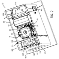
- FIG. 2 is another perspective view of a standby generator with a portion of the enclosure removed;
- FIG. 3 is a side view of the standby generator of FIG. 1 with a portion of the enclosure removed;
- FIG. 4 is another side view of the standby generator of FIG. 1 with a portion of the enclosure removed and illustrating the air flow paths;
- FIG. 5 is a side schematic illustration of a portion of the standby generator illustrating the air flow paths
- FIG. 6 is a top schematic illustration of a portion of the standby generator illustrating the air flow paths within the exhaust manifold;
- FIG. 7 is a top schematic illustration of a portion of the standby generator including an alternative exhaust manifold and illustrating the fluid flow paths within the alternative exhaust manifold;
- FIG. 8 is a section view of the engine of FIG. 3 taken along line 8 - 8 of FIG. 3 ;
- FIG. 9 is a front view of a portion of the engine of FIG. 1 ;
- FIG. 10 is a top view of the engine with a portion of the enclosure removed and illustrating some of the air flow paths.
- FIG. 1 illustrates a standby generator 10 that is suited for use in providing electrical power.
- the standby generator 10 includes a prime mover such as an internal combustion engine 15 , a diesel engine, a rotary engine, or the like, and an alternator 20 .
- the construction illustrated in FIGS. 1-4 includes a two-cylinder internal combustion engine 15 that includes an output shaft 25 .
- the engine 15 illustrated in FIGS. 8 and 9 , is arranged such that the output shaft 25 extends substantially horizontally.
- other constructions may employ other engines or other engine arrangements.
- other constructions may employ a vertical shaft engine that may be coupled to a gearbox or may be directly coupled to the alternator 20 .
- Still other constructions may employ single-cylinder engines or engines with three or more cylinders.
- the engine includes an air-fuel mixing device (not shown), such as a carburetor, and an air cleaner 30 positioned to filter particulate matter from an air stream before the air is directed to the air-fuel mixing device.
- an air-fuel mixing device such as a carburetor
- an air cleaner 30 positioned to filter particulate matter from an air stream before the air is directed to the air-fuel mixing device.
- other construction may employ other fuel mixing devices such as fuel injection without affecting the function of the invention.
- the illustrated engine 15 is an air-cooled engine such as the engine shown and described in U.S. Pat. Nos. 5,813,384 and 6,889,635 the contents of which are fully incorporated herein by reference. Liquid-cooled engines may also be suitable for use in standby generators 10 if desired. With a liquid cooled engine, air that would normally pass over the engine for cooling, passes through a radiator or other heat exchanger. As noted, the engine 15 includes two cylinders 35 with each cylinder 35 including a plurality of fins 40 that improve the cooling efficiency of the engine 15 . As with most air-cooled engines, the illustrated engine 15 includes a fan portion 45 that is coupled to the output shaft 25 such that the fan 45 rotates with the engine output shaft 25 when the engine 15 is operating. The fan 45 is positioned to draw in air and direct that air past the engine cylinders 35 and other engine components to provide the desired cooling for the engine 15 .
- the engine 15 also includes exhaust tubes 50 that extend from each of the cylinders 35 to an exhaust manifold 55 , or muffler.
- the tubes 50 guide hot byproducts of combustion or exhaust produced within the engine 15 during combustion from the cylinders 35 to the exhaust manifold 55 .
- the exhaust manifold 55 is a large cylindrical member having a substantially elliptical cross-section that defines an internal volume.
- the exhaust manifold 55 is sized to receive the engine exhaust and functions to reduce the flow velocity of the exhaust by providing an increased flow area when compared to the flow area of the tubes 50 .
- the exhaust manifold 55 may include baffles 57 (shown in FIGS.
- a first tube 60 (sometimes referred to as an outlet manifold) extends rearward from the exhaust manifold 55 and attaches to a second tube 65 .
- the second tube 65 extends substantially perpendicular to the first tube 60 and includes a plurality of small apertures 70 spaced along the length of the tube 65 that allow for the escape of the engine exhaust.
- the apertures 70 are positioned on the side of the second tube 65 nearest the exhaust manifold 55 such that the exhaust flows in a first direction 75 that is generally from the rear of the standby generator 10 toward the front of the standby generator 10 .
- the alternator 20 of the standby generator 10 includes an alternator shaft (not shown).
- the alternator shaft connects with the output shaft 25 of the engine 15 such that the alternator shaft rotates with the output shaft 25 .
- the alternator 20 extends rearward under the exhaust manifold 55 , the first tube 60 , and the second tube 65 .
- most constructions employ an alternator that generates usable electricity (e.g., 60 hertz).
- other constructions may employ asynchronous alternators, inverters, synchronous or other electrical devices suited to converting rotating mechanical power to electrical power at a desired voltage and frequency.
- the alternator 20 includes a fan 80 that is coupled to the alternator shaft such that the fan 80 rotates with the alternator shaft.
- the alternator 20 also includes, or at least partially defines, one or more passages (not shown) that extend through at least a portion of the alternator 20 .
- the passages provide flow paths for air that in turn cools the alternator 20 during alternator operation.
- the fan 80 draws air into the alternator 20 and through the passages. While many constructions of alternators 20 are available, the illustrated construction is arranged such that the fan 80 is adjacent the front portion of the alternator 20 and is operable to draw air from the rear portion of the alternator 20 . The air flows through the passages and exits the front of the alternator 20 adjacent the fan 80 .
- the engine 15 , exhaust manifold 55 , first tube 60 , second tube 65 , and alternator 20 are all substantially contained within an enclosure 85 .
- the size of the enclosure 85 is as small as possible to reduce the visual impact of the standby generator 10 .
- the standby generator 10 be as small and as quiet as possible.
- the enclosure 85 generally rests on a support structure such as a concrete slab 90 , as illustrated in FIG. 3 .
- a fuel tank (not shown) is disposed within the enclosure 85 with other constructions locating the fuel tank outside of the enclosure 85 . If the fuel is natural gas or the like, the fuel may be supplied via a gas line.
- the enclosure 85 includes a number of openings, apertures, or channels that allow for the entry and exit of air that is used for cooling, as well as for combustion.
- the arrangement of the components within the enclosure 85 is such that the cooling effect of the air flow through the engine 15 is increased.
- the air flow paths are arranged to reduce the noise of the standby generator 10 during operation.
- the rear portion of the alternator 20 is disposed at least partially within an inner housing 95 that is disposed within the enclosure 85 .
- the inner housing 95 cooperates with the enclosure 85 to define an alternator space 100 .
- a pair of intake apertures 101 are formed as part of the enclosure 85 adjacent the space 100 to provide a portion of a flow path between the exterior of the enclosure 85 and the space 100 .
- Louver panels 102 or other aperture covers cover the apertures 101 and inhibit the entry of large particles such as rocks, sticks, and other debris.
- Rubber ducts 103 guide the air from the intake apertures 101 to a duct cover 110 . From the duct cover 110 , the air passes through an aperture 105 into the space 100 adjacent the rear portion of the alternator 20 .
- a wall 115 is positioned between the engine 15 and a front panel 120 of the enclosure 85 to at least partially define an engine chamber 125 .
- the wall 115 includes two apertures 130 , 135 that direct air from the engine chamber 125 to the engine 15 .
- the uppermost aperture 130 directs air from the engine chamber 125 to the air cleaner 30
- the lowermost aperture 135 directs air from the engine chamber 125 to the engine fan 45 .
- An air duct 140 is disposed substantially within the engine chamber 125 and is coupled to the wall 115 such that the air duct 140 at least partially surrounds the two apertures 130 , 135 in the wall 115 , and partially separates the engine chamber 125 into an inlet space 145 and an air duct space 150 .
- the air duct 140 includes an opening 155 near its top that allows air to pass from the inlet space 145 to the air duct space 150 .
- several slots 160 are formed in the air duct 140 near its lower end to allow additional air to flow from the inlet space 145 to the air duct space 150 .
- the front panel 120 of the enclosure 85 includes an engine aperture 165 that provides fluid communication between the exterior of the enclosure 85 and the engine chamber 125 .
- a duct cover 170 is placed or formed over the engine aperture 165 to inhibit the entry of large particles and to force the air to enter the enclosure 85 along a substantially vertical path.
- other covers such as louvers or grates may be used to cover the engine aperture 165 and inhibit the entry of large unwanted particles.
- the enclosure 85 also defines an outlet aperture 175 near the rear of the enclosure 85 .
- the outlet aperture 175 allows for the escape of air from the enclosure 85 .
- an outlet grate 180 , louvers, or another device that inhibits the entry or exit of large particles covers the outlet aperture 175 .
- the engine 15 draws air from the engine chamber 125 in two ways.
- the engine 15 and more specifically the air-fuel mixing device, draws air from the engine chamber 125 for combustion.
- the engine 15 draws air from the engine chamber 125 through the open top portion 155 of the air duct 140 and the lower slots 160 and directs the air into the air cleaner 30 .
- the air cleaner 30 supports a filter element 185 that filters the air to remove unwanted particles before the air is delivered to the fuel-air mixing device where the air and fuel mix to produce a combustible mixture.
- a portion of the combustible mixture flows to each of the cylinders 35 where it is combusted to produce usable power at the output shaft 25 and the flow of engine exhaust.
- the engine exhaust exits each cylinder 35 through the exhaust tubes 50 and flows to the exhaust manifold 55 . From the exhaust manifold 55 , the engine exhaust flows to the first tube 60 , and ultimately to the second tube 65 and out of the second tube 65 . As discussed, the second tube 65 includes apertures 70 that direct the engine exhaust towards the exhaust manifold 55 .
- FIGS. 6 and 7 schematically illustrate two possible flow paths that could be followed by the engine exhaust as the exhaust leaves the engine cylinders 35 .
- the exhaust travels through the exhaust tubes 50 between the cylinders 35 and the exhaust manifold 55 .
- the exhaust tubes 50 are substantially uniform in direction and do not include significant direction changes.
- Baffles 57 may be positioned within the exhaust manifold 55 to force the engine exhaust to follow a circuitous flow path through the exhaust manifold 55 .
- the flow divides into two separate flows that enter the exhaust manifold 55 and turn inward along two flow paths that are substantially perpendicular to the direction at which the exhaust enters the exhaust manifold 55 .
- the flows then substantially reverse direction twice before reaching the outlet of the exhaust manifold 55 .
- Each change in direction aids in reducing the exhaust flow velocity and thus, reduces the noise produced by the exhaust.
- other constructions may include more or fewer baffles 57 or different arrangements of the baffles 57 to arrive at a flow pattern that is desirable.
- FIG. 7 illustrates another construction of the exhaust manifold 55 a in which the first tube 60 a extends through the exhaust manifold 55 a .
- a plurality of apertures 195 are formed in the first tube 60 a in the region disposed within the exhaust manifold 55 a .
- Additional baffles 57 may also be positioned within the exhaust manifold 55 a to direct the incoming exhaust as desired. As the flows reach and surround the first tube 60 a , the exhaust flow enters the first tube 60 a through the apertures 195 .
- the flow of products of combustion enters the first tube 60 , or continues to flow along the first tube 60 a for constructions similar to that shown in FIG. 7 , and flows substantially in a second direction 200 that is generally from the front of the enclosure 85 toward the rear of the enclosure 85 .
- the first tube 60 ends in a T-connection with the second tube 65 .
- the second tube 65 is substantially normal to the first tube 60 with other angles also being possible.
- the engine exhaust flow enters the second tube 65 , the flow is divided into two flow streams that generally flow toward the ends of the second tube 65 and away from one another.
- the engine exhaust flow makes a substantially 90 degree turn as it enters the second tube 65 .
- the two flow streams exit the second tube 65 via the plurality of apertures 70 in the second tube 65 to define an exhaust flow 202 .
- the flows must make another 90-degree turn such that as the flows exit the second tube 65 they are flowing in the first direction 75 , generally opposite the second direction 200 .
- the engine 15 also draws air from the engine chamber 125 using the engine fan 45 to produce a flow of engine cooling air 203 .
- This air stream enters the engine chamber 125 by passing from the atmosphere through the engine aperture 165 .
- the air then flows through the open top 155 of the air duct 140 and the slots 160 to enter the air duct space 150 .
- the fan 45 draws the air from the air duct space 150 and directs the air over the engine cylinders 35 and other components to cool the engine components.
- the air flows toward and around the exhaust manifold 55 , the first tube 60 , and the second tube 65 where the air provides additional cooling to those components.
- the air flows generally in the second direction 200 from the front of the enclosure 85 toward the rear of the enclosure 85 .
- After passing over the exhaust manifold 55 , the first tube 60 , and the second tube 65 the air exits the enclosure 85 via the outlet aperture 175 .
- the fan 80 draws air from the space 100 and through the alternator passages to define a flow of alternator cooling air 205 .
- This arrangement assures that the alternator 20 receives a steady flow of cooling air and inhibits the intake of air that has passed through or around the engine 15 .
- the air After the air exits the alternator 20 , the air is directed upward toward the exhaust manifold 55 .
- the air passes around the exhaust manifold 55 , the first tube 60 , and the second tube 65 to provide additional cooling for these components. Again, the air generally flows in the second direction 200 toward the rear of the enclosure 85 and the outlet aperture 175 .
- the exhaust flow 202 exits the second tube 65 and flows in the first direction 75 toward the exhaust manifold 55 , and the front of the enclosure 85 .
- the engine cooling air 203 and the alternator cooling air 205 flow in generally the opposite direction toward the rear of the enclosure 85 .
- the exhaust flow 202 is eventually reversed and the exhaust flow 202 , the engine cooling air 203 , and the alternator cooling air 205 exit the enclosure 85 via the outlet aperture 175 .
- the numerous flow reversals established within the enclosure 85 serve to improve the cooling efficiency of the system, while simultaneously reducing flow velocities into, out of, and within the enclosure 85 .
- the reduced flow velocities reduce the level of noise produced as the standby generator 10 operates.
- the additional cooling of the exhaust manifold 55 , first tube 60 , and second tube 65 further cools the engine exhaust beyond that which could be achieved without the flow of cooling air past the exhaust manifold 55 , the first tube 60 , and the second tube 65 .
- the additional cooling further reduces the specific volume of the engine exhaust and thus, reduces the flow velocities within the exhaust manifold 55 , the first tube 60 , and the second tube 65 .
- the reduced flow velocities reduce the noise produced by the flow.
- the exhaust flow 202 is further cooled.
- This cooling reduces the specific volume and flow velocity of the exhaust flow 202 , thus further reducing the noise produced by the standby generator 10 as the air and exhaust flow 202 exit the standby generator 10 .
- the reduced temperature of the exhaust flow 202 allows for the use of less expensive plastic materials for the outlet, shields, and other components exposed to the flow instead of engineered plastics or metal alloys.
- each aperture described herein could include a plurality of separate openings that together define the aperture.
- aperture should not be interpreted as requiring that the aperture be a single continuous opening.
- opening should not be interpreted as requiring that the opening be a single continuous hole or aperture.
- the invention provides, among other things, a new and useful standby generator 10 . More particularly, the invention provides a new and useful arrangement for the components within the enclosure 85 of a standby generator 10 that reduces the noise produced during operation of the standby generator 10 .
Abstract
Description
Claims (26)
Priority Applications (1)
| Application Number | Priority Date | Filing Date | Title |
|---|---|---|---|
| US11/417,741 US7314397B2 (en) | 2005-05-13 | 2006-05-04 | Standby generator |
Applications Claiming Priority (2)
| Application Number | Priority Date | Filing Date | Title |
|---|---|---|---|
| US68062205P | 2005-05-13 | 2005-05-13 | |
| US11/417,741 US7314397B2 (en) | 2005-05-13 | 2006-05-04 | Standby generator |
Publications (2)
| Publication Number | Publication Date |
|---|---|
| US20060258237A1 US20060258237A1 (en) | 2006-11-16 |
| US7314397B2 true US7314397B2 (en) | 2008-01-01 |
Family
ID=37419741
Family Applications (1)
| Application Number | Title | Priority Date | Filing Date |
|---|---|---|---|
| US11/417,741 Active US7314397B2 (en) | 2005-05-13 | 2006-05-04 | Standby generator |
Country Status (1)
| Country | Link |
|---|---|
| US (1) | US7314397B2 (en) |
Cited By (33)
| Publication number | Priority date | Publication date | Assignee | Title |
|---|---|---|---|---|
| US20080129053A1 (en) * | 2004-05-12 | 2008-06-05 | Piercey Gerald S | Engine-generator set |
| US20080185048A1 (en) * | 2006-11-22 | 2008-08-07 | Tyson Mellon | Fuel tank for a power generator set |
| US20080238221A1 (en) * | 2007-04-02 | 2008-10-02 | Yamaha Motor Power Products Kabushiki Kaisha | Soundproof type engine generator |
| US20100263343A1 (en) * | 2009-04-15 | 2010-10-21 | Briggs & Stratton Corporation | Air cleaner assembly for small engine |
| US20110017159A1 (en) * | 2009-07-23 | 2011-01-27 | Briggs & Stratton Corporation | Overhead valve and rocker arm configuration for a small engine |
| US20110017336A1 (en) * | 2009-07-23 | 2011-01-27 | Briggs & Stratton Corporation | Muffler attachment system |
| US20110272952A1 (en) * | 2010-01-18 | 2011-11-10 | Christine Richardson | Electrical Generator With Improved Cooling And Exhaust Flows |
| US8251030B2 (en) | 2009-07-23 | 2012-08-28 | Briggs & Stratton Corporation | Rocker cover system |
| USD668607S1 (en) | 2010-03-08 | 2012-10-09 | Briggs & Stratton Corporation | Frame for outdoor power equipment |
| US8424498B2 (en) | 2009-07-23 | 2013-04-23 | Briggs & Stratton Corporation | Engine blower scroll |
| US20130187392A1 (en) * | 2012-01-25 | 2013-07-25 | Briggs & Stratton Corporation | Standby generator |
| US20130213337A1 (en) * | 2012-02-17 | 2013-08-22 | Honda Motor Co., Ltd. | Engine-driven power generator apparatus |
| US8806853B2 (en) | 2012-12-05 | 2014-08-19 | Cummins Powergen Ip, Inc. | System and method for SCR inducement |
| US20150181735A1 (en) * | 2012-07-27 | 2015-06-25 | Caterpillar (Ni) Limited | Enclosure for a generator |
| US9221016B2 (en) | 2012-12-05 | 2015-12-29 | Cummins Cal Pacific, Llc | Exhaust aftertreatment packaging for a diesel genset |
| US20150381013A1 (en) * | 2013-02-15 | 2015-12-31 | Siemens Aktiengesellschaft | Through flow ventilation system for a power generation turbine package |
| US9333466B2 (en) | 2012-12-05 | 2016-05-10 | Cummins Powergen Ip, Inc. | Diesel exhaust fluid injector assembly |
| US9482154B2 (en) | 2012-12-05 | 2016-11-01 | Cummins Cal Pacific, Llc | Exhaust gas collector for an exhaust aftertreatment system |
| USD773395S1 (en) | 2014-09-26 | 2016-12-06 | Cummins Inc. | Genset enclosure |
| US9771847B2 (en) | 2012-12-05 | 2017-09-26 | Cummins Cal Pacific, Llc | Integrated load bank and exhaust heater system with load shed capability for a diesel genset exhaust aftertreatment system |
| US9997977B1 (en) | 2016-02-22 | 2018-06-12 | MWE Investments LLC | Dual engine generator |
| US10079526B2 (en) | 2013-09-27 | 2018-09-18 | Cummins, Inc. | Electrical power generation system with multiple path cooling |
| US10132224B2 (en) | 2015-04-29 | 2018-11-20 | Champion Engine Technology, LLC | Mounting configuration for a heat duct in an electric generator |
| US10186931B2 (en) | 2015-02-06 | 2019-01-22 | Champion Engine Technology, LLC | Electrical generator heat management system |
| US10260409B2 (en) | 2016-02-12 | 2019-04-16 | Evolve Holdings, Inc. | Scalable electrical power generator set and related methods |
| US10309302B2 (en) | 2016-03-09 | 2019-06-04 | Kohler Co. | Noise suppression system |
| US20190353081A1 (en) * | 2018-05-17 | 2019-11-21 | Champion Power Equipment, Inc. | Standby generator air flow management system |
| US20190383213A1 (en) * | 2018-06-15 | 2019-12-19 | Champion Power Equipment, Inc. | Backplate for engine-alternator coupling in standby generator |
| US10744586B2 (en) | 2017-11-28 | 2020-08-18 | Lincoln Global, Inc. | Engine driven welder |
| US10786859B2 (en) | 2017-11-28 | 2020-09-29 | Lincoln Global, Inc. | Engine driven welder |
| USD903596S1 (en) * | 2018-12-11 | 2020-12-01 | N.P.S. Company, LLC | Cover |
| US11591977B2 (en) | 2020-06-03 | 2023-02-28 | Briggs & Stratton, Llc | Inverter generator |
| US11705779B2 (en) | 2020-06-03 | 2023-07-18 | Briggs & Stratton, Llc | Inverter generator |
Families Citing this family (2)
| Publication number | Priority date | Publication date | Assignee | Title |
|---|---|---|---|---|
| EP2479398B1 (en) * | 2011-01-25 | 2017-05-03 | Joseph Vögele AG | Road paver or feeder |
| JP5886551B2 (en) | 2011-07-19 | 2016-03-16 | コベルコ建機株式会社 | Exhaust structure of construction machinery |
Citations (35)
| Publication number | Priority date | Publication date | Assignee | Title |
|---|---|---|---|---|
| US3968649A (en) * | 1973-11-21 | 1976-07-13 | The Rovac Corporation | Exhaust emission control system |
| US4243893A (en) | 1978-11-03 | 1981-01-06 | Aktiebolaget Electrolux | Supplemental cooling system for portable electric power plants |
| US4540888A (en) | 1983-09-12 | 1985-09-10 | Kohler Company | Vertical shaft engine generator set for a recreational vehicle or the like |
| US4548164A (en) | 1984-02-09 | 1985-10-22 | Valmet Oy | Engine driven generator assembly |
| US4677940A (en) | 1985-08-09 | 1987-07-07 | Kohler Co. | Cooling system for a compact generator |
| JPS6356144A (en) | 1986-08-25 | 1988-03-10 | Kubota Ltd | Cooling structure of engine generator |
| US4779905A (en) | 1986-08-25 | 1988-10-25 | Kubato Ltd. | Forcedly air-cooled engine generator of vertical shaft type |
| US4856470A (en) | 1987-12-02 | 1989-08-15 | Kubota Ltd. | Engine working machine assembly with soundproof cover |
| US4859886A (en) | 1986-02-28 | 1989-08-22 | Honda Giken Kogyo Kabushiki Kaisha | Portable engine-operated electric generator |
| US4907546A (en) | 1987-12-02 | 1990-03-13 | Kubota Ltd. | Air-cooled type cooling system for engine working machine assembly |
| US5121715A (en) | 1990-04-13 | 1992-06-16 | Yamaha Hatsudoki Kabushiki Kaisha | Compact power supply |
| US5133637A (en) | 1991-03-22 | 1992-07-28 | Wadsworth William H | Vertical axis wind turbine generator |
| JPH05312050A (en) | 1992-05-01 | 1993-11-22 | Kubota Corp | Ventilating and cooling system in soundproofing type engine generator |
| US5433175A (en) | 1993-11-30 | 1995-07-18 | Onan Corporation | Generator air flow and noise management system and method |
| US5515816A (en) | 1995-05-08 | 1996-05-14 | Ball; Ronald | Electrical generator set |
| US5546901A (en) | 1995-06-30 | 1996-08-20 | Briggs & Stratton Corporation | Engine housing for an engine-device assembly |
| US5556314A (en) * | 1994-03-08 | 1996-09-17 | Sanshin Kogyo Kabushuki Kaisha | Exhaust system for watercraft |
| US5626105A (en) | 1995-10-24 | 1997-05-06 | Kohler Co. | Vertical shaft generator with single cooling fan |
| US5694889A (en) | 1995-05-08 | 1997-12-09 | Ball; Ronald C. | Electrical generator set |
| JPH1182044A (en) | 1997-09-09 | 1999-03-26 | Sawafuji Electric Co Ltd | Engine generator |
| US5890460A (en) | 1995-05-08 | 1999-04-06 | Ball; Ronald C. | Electrical generator set |
| US5899174A (en) | 1998-02-06 | 1999-05-04 | Anderson; Wayne A. | Enclosed engine generator set |
| US5965999A (en) | 1997-03-20 | 1999-10-12 | Coleman Powermate, Inc. | Vertical generator assembly |
| USD418809S (en) | 1998-08-13 | 2000-01-11 | Coleman Powermate, Inc. | Generator system |
| US6067945A (en) | 1997-09-09 | 2000-05-30 | Sawafuji Electric Co., Ltd | Engine generator |
| US6084313A (en) | 1998-08-13 | 2000-07-04 | Coleman Powermate, Inc. | Generator system with vertically shafted engine |
| US6095099A (en) | 1998-04-17 | 2000-08-01 | Honda Giken Kogyo Kabushiki Kaisha | Engine operated working machine |
| US6134878A (en) | 1997-09-24 | 2000-10-24 | Sts Corporation | Cooling arrangement for a gas turbine driven power system |
| US6376944B1 (en) | 2000-07-11 | 2002-04-23 | Eagle-Picher Industries, Inc. | Electrical power generator |
| US6431126B2 (en) | 2000-02-09 | 2002-08-13 | Fuji Jukogyo Kabushiki Kaisha | Engine generator |
| US6492740B2 (en) | 2000-04-14 | 2002-12-10 | Fuji Jukogyo Kabushiki Kaisha | Engine generator |
| US6499441B2 (en) | 2000-04-14 | 2002-12-31 | Fuji Jukogyo Kabushiki Kaisha | Engine generator |
| US20030011196A1 (en) | 2001-07-12 | 2003-01-16 | Kern Robert D. | Air flow arrangement for generator enclosure |
| US6568355B2 (en) | 2000-04-14 | 2003-05-27 | Fuji Jukogyo Kabushiki Kaisha | Engine generator |
| US7004805B2 (en) * | 2002-10-30 | 2006-02-28 | Fineline Industries, Inc. | Directable exhaust for water sport tow boat |
Family Cites Families (2)
| Publication number | Priority date | Publication date | Assignee | Title |
|---|---|---|---|---|
| US492740A (en) * | 1893-02-28 | Gun-clip for bicycles | ||
| SE510248C2 (en) * | 1996-08-01 | 1999-05-03 | Ericsson Telefon Ab L M | Time zone management in telecommunication systems |
-
2006
- 2006-05-04 US US11/417,741 patent/US7314397B2/en active Active
Patent Citations (38)
| Publication number | Priority date | Publication date | Assignee | Title |
|---|---|---|---|---|
| US3968649A (en) * | 1973-11-21 | 1976-07-13 | The Rovac Corporation | Exhaust emission control system |
| US4243893A (en) | 1978-11-03 | 1981-01-06 | Aktiebolaget Electrolux | Supplemental cooling system for portable electric power plants |
| US4540888A (en) | 1983-09-12 | 1985-09-10 | Kohler Company | Vertical shaft engine generator set for a recreational vehicle or the like |
| US4548164A (en) | 1984-02-09 | 1985-10-22 | Valmet Oy | Engine driven generator assembly |
| US4677940A (en) | 1985-08-09 | 1987-07-07 | Kohler Co. | Cooling system for a compact generator |
| US4859886A (en) | 1986-02-28 | 1989-08-22 | Honda Giken Kogyo Kabushiki Kaisha | Portable engine-operated electric generator |
| US4779905A (en) | 1986-08-25 | 1988-10-25 | Kubato Ltd. | Forcedly air-cooled engine generator of vertical shaft type |
| JPS6356144A (en) | 1986-08-25 | 1988-03-10 | Kubota Ltd | Cooling structure of engine generator |
| US4856470A (en) | 1987-12-02 | 1989-08-15 | Kubota Ltd. | Engine working machine assembly with soundproof cover |
| US4907546A (en) | 1987-12-02 | 1990-03-13 | Kubota Ltd. | Air-cooled type cooling system for engine working machine assembly |
| US5121715A (en) | 1990-04-13 | 1992-06-16 | Yamaha Hatsudoki Kabushiki Kaisha | Compact power supply |
| US5133637A (en) | 1991-03-22 | 1992-07-28 | Wadsworth William H | Vertical axis wind turbine generator |
| JPH05312050A (en) | 1992-05-01 | 1993-11-22 | Kubota Corp | Ventilating and cooling system in soundproofing type engine generator |
| US5433175A (en) | 1993-11-30 | 1995-07-18 | Onan Corporation | Generator air flow and noise management system and method |
| US5556314A (en) * | 1994-03-08 | 1996-09-17 | Sanshin Kogyo Kabushuki Kaisha | Exhaust system for watercraft |
| US5694889A (en) | 1995-05-08 | 1997-12-09 | Ball; Ronald C. | Electrical generator set |
| US5515816A (en) | 1995-05-08 | 1996-05-14 | Ball; Ronald | Electrical generator set |
| US5890460A (en) | 1995-05-08 | 1999-04-06 | Ball; Ronald C. | Electrical generator set |
| US5546901A (en) | 1995-06-30 | 1996-08-20 | Briggs & Stratton Corporation | Engine housing for an engine-device assembly |
| US5626105A (en) | 1995-10-24 | 1997-05-06 | Kohler Co. | Vertical shaft generator with single cooling fan |
| US5965999A (en) | 1997-03-20 | 1999-10-12 | Coleman Powermate, Inc. | Vertical generator assembly |
| JPH1182044A (en) | 1997-09-09 | 1999-03-26 | Sawafuji Electric Co Ltd | Engine generator |
| US6067945A (en) | 1997-09-09 | 2000-05-30 | Sawafuji Electric Co., Ltd | Engine generator |
| US6134878A (en) | 1997-09-24 | 2000-10-24 | Sts Corporation | Cooling arrangement for a gas turbine driven power system |
| US5899174A (en) | 1998-02-06 | 1999-05-04 | Anderson; Wayne A. | Enclosed engine generator set |
| US6095099A (en) | 1998-04-17 | 2000-08-01 | Honda Giken Kogyo Kabushiki Kaisha | Engine operated working machine |
| US6084313A (en) | 1998-08-13 | 2000-07-04 | Coleman Powermate, Inc. | Generator system with vertically shafted engine |
| USD418809S (en) | 1998-08-13 | 2000-01-11 | Coleman Powermate, Inc. | Generator system |
| US6181019B1 (en) | 1998-08-13 | 2001-01-30 | Coleman Powermate, Inc. | Generator system with vertically shafted engine |
| US6310404B1 (en) | 1998-08-13 | 2001-10-30 | Coleman Powermate, Inc. | Generator system with vertically shafted engine |
| US6313543B1 (en) | 1998-08-13 | 2001-11-06 | Coleman Powermate, Inc. | Generator system with vertically shafted engine |
| US6431126B2 (en) | 2000-02-09 | 2002-08-13 | Fuji Jukogyo Kabushiki Kaisha | Engine generator |
| US6492740B2 (en) | 2000-04-14 | 2002-12-10 | Fuji Jukogyo Kabushiki Kaisha | Engine generator |
| US6499441B2 (en) | 2000-04-14 | 2002-12-31 | Fuji Jukogyo Kabushiki Kaisha | Engine generator |
| US6568355B2 (en) | 2000-04-14 | 2003-05-27 | Fuji Jukogyo Kabushiki Kaisha | Engine generator |
| US6376944B1 (en) | 2000-07-11 | 2002-04-23 | Eagle-Picher Industries, Inc. | Electrical power generator |
| US20030011196A1 (en) | 2001-07-12 | 2003-01-16 | Kern Robert D. | Air flow arrangement for generator enclosure |
| US7004805B2 (en) * | 2002-10-30 | 2006-02-28 | Fineline Industries, Inc. | Directable exhaust for water sport tow boat |
Cited By (57)
| Publication number | Priority date | Publication date | Assignee | Title |
|---|---|---|---|---|
| US20080129053A1 (en) * | 2004-05-12 | 2008-06-05 | Piercey Gerald S | Engine-generator set |
| US20080185048A1 (en) * | 2006-11-22 | 2008-08-07 | Tyson Mellon | Fuel tank for a power generator set |
| US7795745B2 (en) * | 2006-11-22 | 2010-09-14 | Girtz Industries | Fuel tank for a power generator set |
| US20080238221A1 (en) * | 2007-04-02 | 2008-10-02 | Yamaha Motor Power Products Kabushiki Kaisha | Soundproof type engine generator |
| US7557458B2 (en) * | 2007-04-02 | 2009-07-07 | Yamaha Motor Power Products Kabushiki Kaisha | Soundproof type engine generator |
| US8216333B2 (en) | 2009-04-15 | 2012-07-10 | Briggs & Stratton Corporation | Air cleaner assembly for small engine |
| US20100263343A1 (en) * | 2009-04-15 | 2010-10-21 | Briggs & Stratton Corporation | Air cleaner assembly for small engine |
| US8413760B2 (en) | 2009-07-23 | 2013-04-09 | Briggs & Stratton Corporation | Muffler attachment system |
| US8720392B2 (en) | 2009-07-23 | 2014-05-13 | Briggs & Stratton Corporation | Engine blower scroll |
| US20110017336A1 (en) * | 2009-07-23 | 2011-01-27 | Briggs & Stratton Corporation | Muffler attachment system |
| US8220429B2 (en) | 2009-07-23 | 2012-07-17 | Briggs & Stratton Corporation | Overhead valve and rocker arm configuration for a small engine |
| US8251030B2 (en) | 2009-07-23 | 2012-08-28 | Briggs & Stratton Corporation | Rocker cover system |
| US8251173B2 (en) | 2009-07-23 | 2012-08-28 | Briggs & Stratton Corporation | Muffler attachment system |
| US20110017159A1 (en) * | 2009-07-23 | 2011-01-27 | Briggs & Stratton Corporation | Overhead valve and rocker arm configuration for a small engine |
| US8424498B2 (en) | 2009-07-23 | 2013-04-23 | Briggs & Stratton Corporation | Engine blower scroll |
| US20110272952A1 (en) * | 2010-01-18 | 2011-11-10 | Christine Richardson | Electrical Generator With Improved Cooling And Exhaust Flows |
| US9181865B2 (en) * | 2010-01-18 | 2015-11-10 | Generae Power Systems, Inc. | Electrical generator with improved cooling and exhaust flows |
| USD668607S1 (en) | 2010-03-08 | 2012-10-09 | Briggs & Stratton Corporation | Frame for outdoor power equipment |
| US10181770B2 (en) | 2012-01-25 | 2019-01-15 | Briggs & Stratton Corporation | Standby generator with air intake on rear wall and exhaust opening on front wall |
| US8872361B2 (en) * | 2012-01-25 | 2014-10-28 | Briggs & Stratton Corporation | Standby generators including compressed fiberglass components |
| US20130187392A1 (en) * | 2012-01-25 | 2013-07-25 | Briggs & Stratton Corporation | Standby generator |
| US10044243B2 (en) | 2012-01-25 | 2018-08-07 | Briggs & Stratton Corporation | Standby generator with air intake on rear wall and exhaust opening on front wall |
| US9755480B2 (en) | 2012-01-25 | 2017-09-05 | Briggs & Stratton Corporation | Standby generator including enclosure with intake opening in rear wall and exhaust opening in front wall |
| US9431865B2 (en) | 2012-01-25 | 2016-08-30 | Briggs & Stratton Corporation | Standby generator with removable panel |
| US8667949B2 (en) * | 2012-02-17 | 2014-03-11 | Honda Motor Co., Ltd. | Engine driven power generator apparatus |
| US20130213337A1 (en) * | 2012-02-17 | 2013-08-22 | Honda Motor Co., Ltd. | Engine-driven power generator apparatus |
| US20150181735A1 (en) * | 2012-07-27 | 2015-06-25 | Caterpillar (Ni) Limited | Enclosure for a generator |
| US9554482B2 (en) * | 2012-07-27 | 2017-01-24 | Caterpillar (Ni) Limited | Enclosure for a generator |
| US9482154B2 (en) | 2012-12-05 | 2016-11-01 | Cummins Cal Pacific, Llc | Exhaust gas collector for an exhaust aftertreatment system |
| US10260389B2 (en) | 2012-12-05 | 2019-04-16 | Cummins Cal Pacific, Llc | Integrated load bank and exhaust heater system with load shed capability for a diesel genset exhaust aftertreatment system |
| US9333466B2 (en) | 2012-12-05 | 2016-05-10 | Cummins Powergen Ip, Inc. | Diesel exhaust fluid injector assembly |
| US9771847B2 (en) | 2012-12-05 | 2017-09-26 | Cummins Cal Pacific, Llc | Integrated load bank and exhaust heater system with load shed capability for a diesel genset exhaust aftertreatment system |
| US9957864B2 (en) | 2012-12-05 | 2018-05-01 | Cummins Distribution Holdco Inc. | System and method for SCR inducement |
| US8806853B2 (en) | 2012-12-05 | 2014-08-19 | Cummins Powergen Ip, Inc. | System and method for SCR inducement |
| US9221016B2 (en) | 2012-12-05 | 2015-12-29 | Cummins Cal Pacific, Llc | Exhaust aftertreatment packaging for a diesel genset |
| US9590472B2 (en) * | 2013-02-15 | 2017-03-07 | Siemens Aktiengesellschaft | Through flow ventilation system for a power generation turbine package |
| US20150381013A1 (en) * | 2013-02-15 | 2015-12-31 | Siemens Aktiengesellschaft | Through flow ventilation system for a power generation turbine package |
| US10079525B2 (en) | 2013-09-27 | 2018-09-18 | Cummins, Inc. | Electrical power generation system with multiple path cooling |
| US10079526B2 (en) | 2013-09-27 | 2018-09-18 | Cummins, Inc. | Electrical power generation system with multiple path cooling |
| USD773395S1 (en) | 2014-09-26 | 2016-12-06 | Cummins Inc. | Genset enclosure |
| US10186931B2 (en) | 2015-02-06 | 2019-01-22 | Champion Engine Technology, LLC | Electrical generator heat management system |
| US10132224B2 (en) | 2015-04-29 | 2018-11-20 | Champion Engine Technology, LLC | Mounting configuration for a heat duct in an electric generator |
| US10260409B2 (en) | 2016-02-12 | 2019-04-16 | Evolve Holdings, Inc. | Scalable electrical power generator set and related methods |
| US9997977B1 (en) | 2016-02-22 | 2018-06-12 | MWE Investments LLC | Dual engine generator |
| US10309302B2 (en) | 2016-03-09 | 2019-06-04 | Kohler Co. | Noise suppression system |
| US10744586B2 (en) | 2017-11-28 | 2020-08-18 | Lincoln Global, Inc. | Engine driven welder |
| US10786859B2 (en) | 2017-11-28 | 2020-09-29 | Lincoln Global, Inc. | Engine driven welder |
| US11300034B2 (en) * | 2018-05-17 | 2022-04-12 | Champion Power Equipment, Inc. | Standby generator air flow management system |
| US20190353081A1 (en) * | 2018-05-17 | 2019-11-21 | Champion Power Equipment, Inc. | Standby generator air flow management system |
| US11668227B2 (en) * | 2018-05-17 | 2023-06-06 | Champion Power Equipment, Inc. | Standby generator air flow management system |
| US20220186652A1 (en) * | 2018-05-17 | 2022-06-16 | Champion Power Equipment, Inc. | Standby generator air flow management system |
| US20190383213A1 (en) * | 2018-06-15 | 2019-12-19 | Champion Power Equipment, Inc. | Backplate for engine-alternator coupling in standby generator |
| US11143099B2 (en) * | 2018-06-15 | 2021-10-12 | Champion Power Equipment, Inc. | Backplate for engine-alternator coupling in standby generator |
| US11668233B2 (en) | 2018-06-15 | 2023-06-06 | Champion Power Equipment, Inc. | Backplate for engine-alternator coupling in standby generator |
| USD903596S1 (en) * | 2018-12-11 | 2020-12-01 | N.P.S. Company, LLC | Cover |
| US11591977B2 (en) | 2020-06-03 | 2023-02-28 | Briggs & Stratton, Llc | Inverter generator |
| US11705779B2 (en) | 2020-06-03 | 2023-07-18 | Briggs & Stratton, Llc | Inverter generator |
Also Published As
| Publication number | Publication date |
|---|---|
| US20060258237A1 (en) | 2006-11-16 |
Similar Documents
| Publication | Publication Date | Title |
|---|---|---|
| US7314397B2 (en) | Standby generator | |
| US7492050B2 (en) | Cooling system for a portable generator | |
| US6917121B2 (en) | Power generator unit | |
| US6975042B2 (en) | Engine-driven generator | |
| US5694889A (en) | Electrical generator set | |
| JP3934896B2 (en) | Engine generator | |
| JP4052823B2 (en) | Engine generator | |
| US20120086217A1 (en) | Power Generation Apparatus | |
| EP0950802B1 (en) | Engine operated working machine | |
| AU597040B2 (en) | Arrangement in an air-cooled I.C. engine | |
| US20080081523A1 (en) | Internal combustion engine and outboard motor provided with the same | |
| US5649418A (en) | Integrated power converter cooling system using turbine intake air | |
| US10907527B2 (en) | Standby generator alternator adapter with engine cooling air intake | |
| US20090126658A1 (en) | Generator Cooling System and Method | |
| RU2291545C2 (en) | Cooling system for dynamoelectric machine rotor | |
| US6979912B2 (en) | Engine-driven generator | |
| GB2251031A (en) | Cooling air pick up for gas turbine engine | |
| JP2000097040A (en) | Engine-driven power generating set | |
| JP3934897B2 (en) | Engine generator | |
| US11177720B2 (en) | Standby generator engine-fan-alternator configuration | |
| JPH05187256A (en) | Gas turbine generating device | |
| JP3511362B2 (en) | Outer rotor type multi-pole generator | |
| JPS60145415A (en) | Small size generating device | |
| JP2004011491A (en) | Power generating device | |
| JP3974515B2 (en) | Engine working machine |
Legal Events
| Date | Code | Title | Description |
|---|---|---|---|
| AS | Assignment |
Owner name: BRIGGS & STRATTON POWER PRODUCTS GROUP, LLC, WISCO Free format text: ASSIGNMENT OF ASSIGNORS INTEREST;ASSIGNORS:SODEMANN, WESLEY C.;BRANDENBURG, BILLY;NUSHART, PETER;REEL/FRAME:018620/0720 Effective date: 20060503 |
|
| STCF | Information on status: patent grant |
Free format text: PATENTED CASE |
|
| FEPP | Fee payment procedure |
Free format text: PAYOR NUMBER ASSIGNED (ORIGINAL EVENT CODE: ASPN); ENTITY STATUS OF PATENT OWNER: LARGE ENTITY |
|
| FPAY | Fee payment |
Year of fee payment: 4 |
|
| FPAY | Fee payment |
Year of fee payment: 8 |
|
| AS | Assignment |
Owner name: BRIGGS & STRATTON CORPORATION, WISCONSIN Free format text: MERGER;ASSIGNOR:BRIGGS & STRATTON POWER PRODUCTS GROUP, LLC;REEL/FRAME:042273/0691 Effective date: 20161214 |
|
| MAFP | Maintenance fee payment |
Free format text: PAYMENT OF MAINTENANCE FEE, 12TH YEAR, LARGE ENTITY (ORIGINAL EVENT CODE: M1553); ENTITY STATUS OF PATENT OWNER: LARGE ENTITY Year of fee payment: 12 |
|
| AS | Assignment |
Owner name: JPMORGAN CHASE BANK, N.A., AS COLLATERAL AGENT, IL Free format text: SECURITY INTEREST;ASSIGNOR:BRIGGS & STRATTON CORPORATION;REEL/FRAME:050564/0916 Effective date: 20190927 Owner name: JPMORGAN CHASE BANK, N.A., AS COLLATERAL AGENT, ILLINOIS Free format text: SECURITY INTEREST;ASSIGNOR:BRIGGS & STRATTON CORPORATION;REEL/FRAME:050564/0916 Effective date: 20190927 |
|
| AS | Assignment |
Owner name: JPMORGAN CHASE BANK, N.A., AS COLLATERAL AGENT, ILLINOIS Free format text: SECURITY INTEREST;ASSIGNOR:BRIGGS & STRATTON CORPORATION;REEL/FRAME:053287/0487 Effective date: 20200722 |
|
| AS | Assignment |
Owner name: BRIGGS & STRATTON CORPORATION, WISCONSIN Free format text: RELEASE BY SECURED PARTY;ASSIGNOR:JPMORGAN CHASE BANK, N.A., AS COLLATERAL AGENT;REEL/FRAME:054617/0331 Effective date: 20200821 |
|
| AS | Assignment |
Owner name: WELLS FARGO BANK, NATIONAL ASSOCIATION, AS COLLATERAL AGENT, ILLINOIS Free format text: SECURITY INTEREST;ASSIGNOR:BRIGGS & STRATTON, LLC;REEL/FRAME:053838/0046 Effective date: 20200921 |
|
| AS | Assignment |
Owner name: KPS CAPITAL FINANCE MANAGEMENT, LLC, NEW YORK Free format text: SECURITY INTEREST;ASSIGNOR:BRIGGS & STRATTON, LLC;REEL/FRAME:053850/0192 Effective date: 20200921 Owner name: BRIGGS & STRATTON CORPORATION, WISCONSIN Free format text: RELEASE BY SECURED PARTY;ASSIGNOR:JPMORGAN CHASE BANK, N.A., AS COLLATERAL AGENT;REEL/FRAME:053885/0211 Effective date: 20200921 |
|
| AS | Assignment |
Owner name: BRIGGS & STRATTON, LLC, WISCONSIN Free format text: ASSIGNMENT OF ASSIGNORS INTEREST;ASSIGNOR:BRIGGS & STRATTON CORPORATION;REEL/FRAME:057042/0247 Effective date: 20200921 |