US7324549B2 - Synchronisation communication systems - Google Patents
Synchronisation communication systems Download PDFInfo
- Publication number
- US7324549B2 US7324549B2 US10/378,653 US37865303A US7324549B2 US 7324549 B2 US7324549 B2 US 7324549B2 US 37865303 A US37865303 A US 37865303A US 7324549 B2 US7324549 B2 US 7324549B2
- Authority
- US
- United States
- Prior art keywords
- bus
- data
- idle
- message
- node
- Prior art date
- Legal status (The legal status is an assumption and is not a legal conclusion. Google has not performed a legal analysis and makes no representation as to the accuracy of the status listed.)
- Active, expires
Links
Images


Classifications
-
- H—ELECTRICITY
- H04—ELECTRIC COMMUNICATION TECHNIQUE
- H04L—TRANSMISSION OF DIGITAL INFORMATION, e.g. TELEGRAPHIC COMMUNICATION
- H04L12/00—Data switching networks
- H04L12/28—Data switching networks characterised by path configuration, e.g. LAN [Local Area Networks] or WAN [Wide Area Networks]
- H04L12/46—Interconnection of networks
-
- H—ELECTRICITY
- H04—ELECTRIC COMMUNICATION TECHNIQUE
- H04J—MULTIPLEX COMMUNICATION
- H04J3/00—Time-division multiplex systems
- H04J3/02—Details
- H04J3/06—Synchronising arrangements
- H04J3/0635—Clock or time synchronisation in a network
- H04J3/0685—Clock or time synchronisation in a node; Intranode synchronisation
-
- H—ELECTRICITY
- H04—ELECTRIC COMMUNICATION TECHNIQUE
- H04J—MULTIPLEX COMMUNICATION
- H04J3/00—Time-division multiplex systems
- H04J3/02—Details
- H04J3/06—Synchronising arrangements
- H04J3/07—Synchronising arrangements using pulse stuffing for systems with different or fluctuating information rates or bit rates
Definitions
- the present invention is concerned with synchronisation of baseband communications in a wireless communications network.
- a bus protocol is used to communicate between different nodes.
- the present invention is concerned particularly but not exclusively with communication between baseband (BB) and radio frequency (RF) nodes in the base transceiver station.
- Nodes are implemented in a plurality of different ways, and in the following description it is understood that the term “node” implies any appropriate hardware unit, for example an ASIC, processor or FPGA, etc.
- the bus protocol used between the different nodes of the base transceiver station is used to transfer digitised transmitter (TX) and receiver (RX) samples as well as other information.
- the present invention addresses the problem of synchronising a bus, in particular a high speed bus operating a bus protocol used for communication between different nodes in a base transceiver station.
- It is a further aim of the present invention is to provide a frame format used in conjunction with synchronisation methods for synchronising communications on a multi-mode communications bus, which does not require complex circuitry.
- the invention relates to bus synchronisation using idle codes, with the possibility of detecting 8b10b decoding status.
- initial synchronisation and synchronisation at run time is discussed.
- the position in a frame and value of the idle code is utilised.
- a method of transmitting data at a line rate from a wireless interface to a bus operating at a bus rate comprising transmitting the data in a packet format consisting of a plurality of frames each having a plurality of time slots, each time slot having successive message groups, wherein each message group comprises a plurality of data messages containing said data and an idle code containing no said data; wherein the number of idle codes in each frame is selected so that the bus rate matches the line rate.
- a method of transmitting data at a line rate from a wireless interface to a bus operating at a bus rate comprising transmitting the data in a packet format consisting of a plurality of frames each having a plurality of time slots, each time slot having successive message groups, wherein each message group comprises a plurality of data messages containing said data and an idle code containing no said data; wherein the number of idle codes in each frame is selected so that the bus rate matches the line rate.
- a communication bus operable at a bus rate and having at least a first node and a second node that are linked by communication channels for transmitting at said bus rate data generated at a line rate, said first node having a transmitting element and said second node having a receiving element, wherein the transmitting element of said first node is operable to transmit data in a packet format consisting of a plurality of frames each having a plurality of time slots, each time slot having successive message groups, wherein each message group comprises a plurality of data messages containing said data and an idle code containing no said data; wherein said number of idle codes in each frame is selected so that the bus rate matches the line rate and wherein the receiving element of the second node is arranged to detect said idle codes for synchronisation purposes.
- a method of synchronising a data communication over a bus in a packet format said data having been generated at a line rate over a wireless interface consisting of a plurality of frames each having a plurality of time slots, each time slot having successive message groups, wherein each message group comprises a predetermined number of data messages containing said data and an idle code containing no said data, the method comprising detecting at a bus node said idle codes until a predetermined number of said idle codes have been detected indicating successful synchronisation.
- a method of synchronising data communication via a bus connecting first and second nodes comprising: transmitting from the first node a plurality of bytes, each byte representing a 10 bit sequence as an 8 bit code; receiving and decoding said bytes at the second node, whereby any 8b10b encoding errors in a byte are detected; and indicating a synchronised status for the bus based on the detection of received bytes which do not contain 8b10b decoding errors.
- a method of synchronising data communication via a bus connecting first and second nodes comprising: transmitting from the first node a plurality of bytes, each byte representing a 10 bit sequence as an 8 bit code; receiving and decoding said bytes at the second node, whereby any 8b10b encoding errors in a byte are detected; and indicating an unsynchronised status for the bus based on the detection of received bytes containing 8b10b decoding errors.
- FIG. 1 shows the basic structure of a wireless communications network
- FIG. 2 shows the context of the present invention for use at baseband frequencies
- FIG. 3 shows an embodiment of the architecture of the physical baseband bus of the present invention
- FIG. 4 shows the baseband bus protocol stack according to an embodiment of the present invention
- FIG. 5 shows a frame format according to an embodiment of the present invention
- FIG. 6 shows an embodiment of the message structure of the present invention
- FIG. 7 shows two communicating nodes of the baseband bus
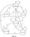
- FIG. 8 shows a state transition diagram of the logic implemented within the receiving elements of each baseband node
- FIG. 9 shows a state transition diagram of the logic implemented within the transmitting elements of each baseband node.
- FIGS. 10 a and 10 b show the bit patterns for the idle codes according to an embodiment of the present invention.
- FIG. 1 shows the traditional elements of a wireless communications network.
- a Mobile Switching Center (MSC) 2 acts as an interface with other networks, for example the Public Switched Telephone Network (PSTN).
- PSTN Public Switched Telephone Network
- the MSC 2 controls a plurality of Base Station Controller's (BSC) 4 , where each BSC 4 in turn controls plurality of Base Transceiver Stations (BTS) 6 .
- BSC Base Station Controller's
- BTS Base Transceiver Stations
- Each BTS 6 has a certain coverage area known as a “cell”, which is used to communicate with mobile stations in their respective coverage areas.
- FIG. 2 shows the typical components of a transceiver used in wireless networks where radio signals are transmitted and received using antennae 10 . These radio signals are transferred at a carrier frequency determined by a carrier generator 14 . Spectrum allocations are licensed and will vary depending on the country involved and the type of air interface being used, for example WCDMA, GSM, etc.
- a typical transceiver for example as would be found at each of the BTS's 6 of FIG. 1 , there is a baseband circuitry 16 concerned with the processing of baseband signals. These baseband signals are then converted into a carrier signal by RF circuitry 12 for transmission by the antennae 10 .
- the embodiments of the present invention discussed herein are in the context of the baseband circuitry 16 , where a bus protocol connects BB and RF nodes together.
- FIG. 3 shows the physical architecture of the baseband bus where nodes 20 , 22 , 24 , 26 are chained in a point-to-point manner according to a first embodiment of the present invention.
- Each of the nodes can be implemented by using an Application Specific Integrated Circuit (ASIC).
- ASIC Application Specific Integrated Circuit
- the nodes communicate using a first set of communication channels 28 in an Uplink direction and over a second set of communication channels in the opposite or Downlink direction 30 .
- Each of the nodes are shown as having a plurality of communication channels referred to herein as links, i.e. 1 to k, in either direction.
- Some of the nodes may have an RF interface.
- Other nodes are baseband nodes with no RF interface.
- Packetised data may be sent over the baseband bus.
- the bus is implemented using a plurality of links. A single link is however possible.
- the baseband bus consists of point-to-point connections forming a chained bus.
- the point-to-point connections are achieved using Low Voltage Differential Signalling (LVDS).
- LVDS Low Voltage Differential Signalling
- the baseband bus uses a three-layer protocol with fixed length messages. Any information to be sent over the baseband bus is packed into messages of known type.
- the three layers are shown in FIG. 4 .
- the physical layer 60 is responsible for the transmission of messages and includes framing, coding and serialisation of the messages.
- the transport layer 62 is responsible for the end-to-end delivery of the messages or routing of the messages.
- the application layer 64 provides the mapping of different types of packets to the payload.
- data at the application layer is continuous, but for transfer over the bus, the continuous data of the application layer is time sliced into short messages that are transferred over the high-speed physical layer. At the receiving node a continuous stream is recovered.
- FIG. 5 shows a frame 70 of the physical layer with a certain packet format being sent over the bus in both the uplink and downlink directions.
- the frame has a fixed 10 ms period. Frames are inserted consecutively onto the bus.
- a frame is split into fifteen timeslots 72 where each timeslot contains a plurality of message groups 74 .
- Each message group 74 has a fixed predetermined number of data messages 76 , one control message 78 and an IDLE message 80 .
- FIG. 6 A preferred embodiment of the message structure 76 is shown in FIG. 6 . These messages are transmitted over the physical layer 60 shown in FIG. 4 .
- the messages are of a fixed length of 19 bytes having a header portion 90 of 3 bytes and a payload portion 92 of 16 bytes.
- the idle message is in the form of an idle byte.
- the physical layer 60 transmits an empty message, which can be implemented by transmitting “1” bits for the entire message.
- the physical layer at the receiving node will detect the existence of an empty message and rejects such messages, thereby making these messages invisible to the upper protocol layers 62 , 64 .
- the message group 74 comprises one control message 78 inserted after every twenty data messages 76 and an IDLE byte 80 inserted after the control message 78 .
- the same IDLE byte 80 is used at the end of each message group 74 with the exception that a special IDLE byte 82 is used in the final timeslot to identify the end of the frame. The significance of the special IDLE byte 82 will be discussed later.
- the bus speed is chosen to be 768 Mbps.
- a derivative of the BTS reference system clock is used as a clock for the baseband bus and the physical layer 60 of the bus protocol is synchronised to the BTS system clock.
- application layers of the bus protocol can operate asynchronously with respect to the timing of the physical layer, which is especially useful for GSM or EDGE application where data is not continuous but instead is transmitted in bursts and is inherently asynchronous.
- FIG. 3 shows a plurality, i.e. 1 to k links being used to communicate in either direction.
- FIG. 7 shows the LVDS point-to-point connections in an uplink direction 30 and a downlink direction 28 between a first node 20 and a second node 22 of the bus.
- Each LVDS point-to-point connection corresponds to each of the 1 to k links shown in the uplink 28 or downlink directions 30 of FIG. 3 .
- Each node 20 , 22 comprises a transmission element 40 , 48 and a receiving element 44 , 52 .
- a transmission element 40 transmits information from a first node 20 to a receiving element 44 in a second node 22 using LVDS connections.
- a transmitting element 48 transmits information from a second node 22 to the receiving element 52 of a first node 20 .
- a communication channel 41 exists between the transmitter 40 and receiver 52 of the first node 20 . Also, a communication channel 43 exists between receiver 44 and transmitter 48 of the second node 22 . These communication channels may be used by receivers on a node to inform the transmitters if a loss of synchronisation occurs.
- each of the transmitting 40 , 48 and receiving elements 44 , 52 have their own respective state machine logic 42 , 46 , 50 , 54 .
- FIG. 8 is a state transition diagram showing the state machine logic 46 , 54 of the receiving elements 44 , 52 .
- FIG. 9 is a state transition diagram showing the state machine logic 42 , 50 of the transmitting elements 40 , 48 . Tables 1, 2 and 3 given below can be used to interpret these state transition diagrams.
- Table 1 below provides a definition of the signals used in the state machine for synchronisation.
- FIG. 10 a and FIG. 10 b show the bit patterns that make up the K28.5 and K28.7 idle bytes respectively, in the 8 bit domain. These bit patterns are known as so-called “comma characters”, which are uniquely chosen to indicate possible errors.
- codes (and other data bytes) are transmitted as 10 bits using an 8b10b encoding scheme, for example as described in “A DC-Balanced, Partitioned-Block, 8B/10B Transmission Code”, by Widmer and Franaszek, IBM J. Res. Develop. Vol. 27 No. 5, September 1983.
- the transmitter has means for encoding the 8b bytes into 10b codes and the receiver has means for decoding the codes and for error checking.
- Table 2 below defines the state transitions and triggers required for these transitions for the state machine logic 46 , 54 of the receiving elements 44 , 52 .
- Table 3 below defines the state transitions and triggers required for these transitions for the state machine logic 42 , 50 of the transmitting elements 40 , 48 .
- initial synchronisation allows an initial check on the link quality of the bus
- frame synchronisation allows continuous monitoring of the link quality when the bus is in run time mode.
- the synchronisation algorithms can report link status information of the bus to upper layers of the protocol stack.
- Initial synchronisation is performed when a bus node is booting up.
- the purpose of the initial synchronisation is to determine the status of each bus interface. That is, checking the status of a node's transmitting and receiving elements. Synchronisation may be unsuccessful due to a missing neighbouring node or a failure of the link.
- sequence of steps for initial synchronisation is the following:
- the above synchronization algorithm can be generalized by considering validity of consecutive received bytes instead of message groups. Furthermore, synchronization can be based on any transmitted data and the success or failure of 8b10b decoding; not just transmission and reception of IDLE bytes.
- the physical layer 60 contains a status register 45 for each transmitting and receiving element of each node of the bus indicating the synchronisation status. For example, DISABLE (000001), UNSYNCHRONISED (000010), SYNCHRONISED (000100). Other state encodings may be used.
- IDLE bytes are sent in UNSYNCHRONIZED and SYNCHRONIZED states. Note that during initial synchronisation, only IDLE bytes are transmitted to the bus. This is not the case in run-time operation when data is transferred over the bus.
- parameter SET_RUN-TIME_MODE is set equal to 1
- frame synchronisation can be performed.
- messages e.g. data, control or even empty
- run-time mode receiver synchronization of a transceiver is started immediately.
- value of parameter SET_RUN-TIME_MODE is changed from 1 to 0, state of the transceiver is changed to FRAME_DISABLE.
- each transmitting element 40 , 48 synchronises the frame timing with the baseband bus frame clock. Furthermore, the status of the frame synchronisation in each receiving element 44 , 52 is constantly monitored. The end of each frame is identified from the unique IDLE byte K28.7. This unique IDLE byte allows one to calculate the received frame offset as well as monitoring of frame synchronization status.
- frame synchronisation is applied to all the transmitting and receiving elements of the bus nodes when entering the run time mode and the sequence of steps for frame synchronisation is the following:
- FRAME_DISABLE_T The value of FRAME_DISABLE_T is always larger or equal to the value of FRAME_UNSYNC_T
- the status register 45 maintains an indication of the status of the frame where the status FRAME_DISABLE, FRAME_UNSYNCHRONIZED, and FRAME_SYNCHRONIZED correspond to the states 001000, 010000, and 100000 respectively. Other state encodings may also be used.
- the transmitting or receiving elements enter the FRAME_DISABLE state, the application layer is informed by an interrupt, which can then restart the synchronization procedure.
- valid messages are sent in the FRAME_SYNCHRONIZED state, whereas empty messages are sent in the FRAME_UNSYNCHRONIZED and FRAME-DISABLE states.
- the idle bytes inserted into the frames at the physical layer level are to synchronise the line rate of data transmission to the bus rate set up by the system clock.
- synchronisation algorithms using these idle bytes to perform different types of synchronisation algorithms.
- the quality of the communication links between the nodes are tested by transmitting message groups that consist purely of idle codes instead of data messages.
- the receiving elements then check the received idle codes and if all idle codes (i.e. 400 idle bytes in this embodiment) have been received correctly, then that message group is said to be valid. If SYNC_T consecutive valid message groups are received then initial synchronisation has been achieved,
- the first algorithm is when the bus is in run time mode but the frames are unsynchronised.
- each transmitting or receiving element of each node of the bus can independently assume any of the states described herein.
- FIG. 3 shows a plurality of links, i.e. 1 to k.
- the present invention is scaleable to adapt to different data rates.
- the frame structure shown in FIG. 5 is one embodiment of the present invention.
- the special IDLE code 82 is inserted at the end of a frame 70 .
- the baseband bus is a multi-mode bus and in conjunction with the layered protocol stack it is intended to support a variety of different air interfaces such as GSM or EDGE.
- the IDLE bytes 80 it should be appreciated that the position of the IDLE byte within the message group 74 may vary in different implementations.
- the special IDLE byte 82 might be implemented at other locations in each frame, for example at the start as opposed to the end of the frame 70 : all that is needed is that it is in a predetermined known location.
- the IDLE codes are 1 byte in length in the described embodiment, however for a different embodiment these IDLE codes could be scaled in length so as to match a different frame format.
- nodes of the communications bus are not necessarily limited to ASIC's and can also be implemented using other logical devices, for example a Field Programmable Gate Array (FPGA) devices.
- FPGA Field Programmable Gate Array
Abstract
Description
| TABLE 1 | ||
| Signal | Definition | Active state |
| NdFifoValid | Node clock domain Fifo | Active high = ‘1’, default = |
| valid signal to indicate that | ‘0’ | |
| the fifo is passing valid | ||
| bytes to the rx decoder | ||
| FRAME_IDLE_VALID | Frame IDLE byte (K28.7) | Active high = ‘1’ for a single |
| is received to indicate that | cycle when a K28.7 IDLE | |
| a new frame boundary is | byte is received. Default = | |
| present. | ‘0’ | |
| SET_RUN_TIME_MODE | Value ‘1’ enables run time | Active high = ‘1’, default = |
| mode, ‘0’ disables run time | ‘0’ | |
| mode. Messages are | ||
| transferred over the bus in | ||
| run-time mode. | ||
| ENABLE_BUS_TRANSCEIVER | The bus transceiver is | Active high = ‘1’, default = |
| enabled by value ‘1’. This | ‘0’ | |
| enables the transmitter to | ||
| start sending IDLE. | ||
| RESTART_FROM_DISABLE | This signal resets the state | Single cycle Active high |
| machine when the state is | pulse = ‘1’, default = ‘0’ | |
| either DISABLE or | ||
| FRAME_DISABLE. | ||
| TABLE 2 | |||
| | Trigger | Comment | |
| 1 | ENABLE_BUS_TRANSRECEIVER=‘1’ (values | Message Group counter reset. |
| changes from ‘0’ to ‘1’) | ||
| 2 | SYNC_T valid Message Groups received | SYNC_T message groups of |
| valid IDLE bytes have been | ||
| received | ||
| 3 | DISABLE_T Message Groups or | Timeout counter has been |
| ENABLE_BUS_TRANSCEIVER=‘0’ | reached without SYNC_T valid | |
| Message Groups being | ||
| received or Application layer | ||
| forces the state to DISABLE. | ||
| 4 | Not (2 or 3) | < SYNC_T valid Message |
| Groups have been received and | ||
| timeout count has not been | ||
| reached | ||
| 5 | RESTART_FROM_DISABLE = ‘1’ | Application layer has |
| acknowledged that the state | ||
| machine is in the DISABLE | ||
| state and restarts the | ||
| |
||
| 6 | UNSYNC_T consecutive invalid Message | Synchronization lost due to |
| Groups received | UNSYNC_T consecutive invalid | |
| Message Groups received | ||
| 7 | Not (6 or 8 or 10) | Physical layer synchronization is |
| maintained and valid IDLE bytes | ||
| are being received. | ||
| 8 | ENABLE_BUS_TRANSCEIVER = ‘0’ | The transceiver is DISABLED. |
| This transition is forced by | ||
| Application layer. | ||
| 9 | RESTART_FROM_DISABLE = ‘0’ | Wait in the DISABLE for the |
| Application layer to generate a | ||
| RESTART_FROM_DISABLE | ||
| signal. | ||
| 10 | SET_RUN_TIME_MODE = ‘1’ & | Run time mode has been |
| FRAME_IDLE_VALID | activated and a K28.7 frame | |
| boundary IDLE byte received to | ||
| indicate the start of empty | ||
| messages. | ||
| 11 | Not (12 or 13) | Stay in the |
| state | ||
| 12 | FRAME_SYNC_T consecutive valid | |
| message groups are received | ||
| 13 | FRAME_DISABLE_T invalid message | Transition to the |
| groups are received or | FRAME_DISABLE state as | |
| ENABLE_BUS_TRANSCEIVER = ‘0’ or | FRAME_DISABLE_T invalid | |
| SET_RUN_TIME = ‘0’ | message groups have been | |
| received or Application layer | ||
| halts the transceiver. | ||
| 14 | Not 15 | Wait for a |
| RESTART_FROM_DISABLE | ||
| signal. | ||
| 15 | RESTART_FROM_DISABLE = ‘1’ | The state machine has been |
| reset by Application layer (i.e. | ||
| restart the initialisation | ||
| process). | ||
| 16 | Not (17 or 18) | Valid Message Groups are |
| being received. Normal | ||
| message reception state. | ||
| 17 | FRAME_UNSYNC_T consecutive invalid | Whilst in the FRAME_SYNC |
| message groups are received | state, FRAME_UNSYNC_T | |
| consecutive invalid message | ||
| groups are received. | ||
| 18 | ENABLE_BUS_TRANSCEIVER = 0 or | Transceiver DISABLE |
| SET_RUN_TIME=‘0’ | ||
| 20 | GO_TO_FRAME_SYNC =1 & | For test purposes: Run time |
| SET_RUN_TIME_MODE=1 & | mode has been activated and a | |
| FRAME_IDLE_VALID | K28.7 frame boundary IDLE | |
| byte received to indicate the | ||
| start of the empty packet bytes. | ||
| 19 | SET_RUN_TIME_MODE = ‘1’ & | When in UNSYNCHRONIZED |
| FRAME_IDLE_VALID | state, run time mode has been | |
| activated and a K28.7 frame | ||
| boundary IDLE byte received to | ||
| indicate the start of empty | ||
| messages. | ||
| TABLE 3 | |||
| | Trigger | Comment | |
| 1 | ENABLE_BUS_TRANSCEIVER=‘1’ | LOS in receiver is initially “1” |
| (values changes from ‘0’ to ‘1’) | ||
| 2 | LOS = ‘0’ | Receiver has acknowledged that |
| SYNC_T IDLE bytes have been | ||
| received. Receiver has | ||
| acknowledged the transition to | ||
| SYNCHRONISED state by | ||
| changing LOS to “0” | ||
| 3 | ENABLE_BUS_TRANSCEIVER = ‘0’ | Transmitter has been DISABLE. |
| 4 | ENABLE_BUS_TRANSCEIVER = ‘0’ and | Wait for Receiver to acknowledge |
| LOS = ‘1’ | receipt of SYNC_T IDLEs or | |
| transmitter DISABLE. | ||
| 19 | GO TO FRAME SYNC = | Go to Frame UNSYNC state |
| ‘1’ | ||
| 5 | RESTART FROM DISABLE = | Transmitter has been reset and |
| ‘1’ | can transition to | |
| UNSYNCHRONISED and start | ||
| sending IDLE. | ||
| 6 | LOS = ‘1’ | Receiver has generated a Loss Of |
| Signal. | ||
| 7 | LOS = ‘0’ AND | Send IDLE bytes (with K28.7 at |
| ENABLE BUS TRANSCEIVER = ‘1' | Frame boundary). | |
| and | ||
| SET RUN-TIME MODE = | ||
| ‘0’ | ||
| 8 | ENABLE BUS TRANCEIVER = | Transition to the DISABLE state. |
| ‘0’ | ||
| 9 | RESTART FROM DISABLE = | Stay in Disable state |
| ‘0’ | ||
| 10 | SET RUN-TIME MODE = | Transition to the |
| ‘1’ and FClk = ‘1’ | FRAME_UNSYNC when the | |
| transmitter has sent a K28.7 (last | ||
| byte in the frame. | ||
| 11 | LOS = ‘1’ AND (ENABLE BUS | Stay in Frame_Unsync state |
| TRANCEIVER) = ‘1’ OR SET RUN-TIME | ||
| MODE = ‘1’) | ||
| 12 | LOS = ‘0’ | Receiver has acknowledged that it |
| has received FrameUnsyncT valid | ||
| Message Groups. | ||
| 13 | ENABLE BUS TRANSCEIVER = | Go to FrameDisable state as the |
| ‘0’ | Transmitter has been DISABLE. | |
| 14 | RESTART FROM DISABLE = | Stay in Disable state. |
| ‘0’ | ||
| 15 | RESTART FROM DISABLE = | Restart the transmitter go to the |
| ‘1’ | UNSYNCHRONISED state. | |
| 16 | LOS = ‘0’ AND | Stay in Frame_Sync state. |
| ENABLE BUS TRANSCEIVER = | ||
| ‘1’ AND | ||
| SET TUN-TIME MODE =‘1’ | ||
| 17 | LOS = ‘1’ | Receiver has de-asserted the |
| Loss Of Signal input so the | ||
| transmitter must send empty | ||
| messages. | ||
| 18 | ENABLE BUS TRANSCEIVER = | Disable Transmitter |
| ‘0’ OR | ||
| SET RUN-TIME MODE = | ||
| ‘0’ | ||
-
- Set state to UNSYNCHRONIZED.
- Reset the message group counter to zero.
- Start transmitting a constant stream of IDLE bytes from the transmitting element of any node, e.g. 20.
- Start reading the IDLE bytes at the receiving element of any node, e.g. 22.
- A message group is considered to be valid when all the IDLE bytes are properly received and there are no 8b10b decoding errors. Otherwise, a message group is considered to be invalid. It should be appreciated that there are (21 messages*19 bytes per message)+1 IDLE byte=400 bytes in a message group.
- When in the state UNSYNCHRONIZED and a value of SYNC_T consecutive valid message groups have been received, the state of the state machine then is set to the SYNCHRONISED state.
- When in the state SYNCHRONIZED and a value of UNSYNC_T consecutive invalid message groups have been received, the state of the state machine then is set to the UNSYNCHRONISED state. Also, the message group counter is set to zero.
- When in the state UNSYNCHRONIZED and a value of DISABLE_T message groups have been received, the state of the state machine then is set to the DISABLE state. The value of DISABLE_T is larger or equal to the value of UNSYNC_T. When either of the transmitting or receiving elements of a node enter the DISABLE state, the
application layer 64 is informed by an interrupt which then can restart the synchronization procedure.
-
- Set the state of the state machine to FRAME_UNSYNCHRONIZED.
- Reset the message group counter to zero.
- Start transmitting empty or other valid messages from the transmitting
element - With reference to the baseband bus frame clock, read the IDLE byte of each message group from the received byte stream using the receiving
element 44, 52. The IDLE byte must be the last byte of the message group and any other IDLE bytes are considered to be errors. - When the IDLE byte of a message group has been properly received and no 8b10b decoding errors are present, consider that message group to be valid. Otherwise, the received message group is invalid.
- When in the state FRAME_UNSYNCHRONIZED and FRAME_SYNC_T consecutive valid message groups have been received, set the state to FRAME_SYNCHRONISED.
- When in the state FRAME_SYNCHRONIZED and FRAME_UNSYNC_T consecutive invalid Message Groups have been received, set the state to FRAME_UNSYNCHRONISED and reset the message group counter to zero.
- When in the state FRAME_UNSYNCHRONIZED and FRAME_DISABLE_T message groups have been received, set the state to FRAME_DISABLE.
-
- Restart the message group counter.
- The transmitting element starts sending IDLE bytes.
- The LOS is set to ‘1’.
- The receiving element waits to receive data.
- Valid bytes are beginning to be passed.
- Initial byte synchronization is performed using the consecutive K28.5 idle code
- The receiving element will start counting valid message groups. If SYNC_T consecutive valid message groups are received, then the state machine transitions to the SYNCHRONIZED state.
- If DISABLE_T message groups are received (with 400 bytes in each), then the state machine transitions to the DISABLE state and the Receiver and Transmitters are disabled.
- If ENABLE_BUS_TRANSCEIVER=0 is received, then the state machine transitions to the DISABLE state.
- If SET_RUN_TIME_MODE=1, then the state machine transitions to the FRAME_UNSYNCHRONISED state.
SYNCHRONISED - Reset the message group counter.
- Set the LOS to ‘0’
- If UNSYNC_T consecutive invalid message groups are received, then the state machine transitions to the UNSYNCHRONISED state.
- If SET_RUN_TIME_MODE=1, then the state machine transitions to the FRAME_UNSYNCHRONISED state.
- If ENABLE_BUS_TRANSCEIVER=0, then the state machine transitions to the DISABLE state.
DISABLE - Stop all counters.
- Set the LOS to ‘1’.
- In this state, the state machine of the receiving element can only transfer to the UNSYNCHRONISED state when RESTART_FROM_DISABLE=1.
FRAME_SYNC - Set the LOS to ‘0’.
- Restart the message group counter.
- Constantly check the frame synchronization using the K28.7 IDLE byte.
- If FRAME_UNSYNC_T consecutive invalid message groups are received, then the state machine transitions to the FRAME_UNSYNCHRONISED state.
- If ENABLE_BUS_TRANSCEIVER=0 or SET_RUN TIME MODE=0, then the state machine transitions to the FRAME_DISABLE state.
- In the FRAME_SYNC state, a valid message group exists when a K28.5 or K28.7 IDLE byte code is at byte 399 and there are no invalid IDLE codes in
bytes 0 to 398 and no 8b10b decoding errors are present.
FRAME_UNSYNC - Set the LOS to ‘1’.
- Restart the message group counter.
- If FRAME_SYNC_T consecutive valid message groups are received, then the state machine transitions to the FRAME_SYNCHRONIZED state.
- If FRAME_DISABLE_T invalid message groups are received, then the state machine transitions to the FRAME_DISABLE state.
- In the FRAME_UNSYNC state, a valid message group exists when a K28.5 or K28.7 IDLE byte code is at byte 399 and there are no invalid IDLE codes in
bytes 0 to 398 and no 8b10b decoding errors are present. - If ENABLE_BUS_TRANSCEIVER=0 or SET_RUN_TIME_MODE=0, then the state machine transitions to the FRAME_DISABLE state.
FRAME_DISABLE - Stop all counters.
- Set the LOS to ‘1’.
Claims (16)
Priority Applications (2)
| Application Number | Priority Date | Filing Date | Title |
|---|---|---|---|
| US11/822,570 US20080019401A1 (en) | 2002-03-02 | 2007-07-06 | Synchronisation in communication systems |
| US11/987,760 US20080181257A1 (en) | 2002-03-05 | 2007-12-04 | Synchronisation in communication systems |
Applications Claiming Priority (2)
| Application Number | Priority Date | Filing Date | Title |
|---|---|---|---|
| GB0205142.3 | 2002-03-05 | ||
| GBGB0205142.3A GB0205142D0 (en) | 2002-03-05 | 2002-03-05 | Synchronisation in communication systems |
Related Child Applications (2)
| Application Number | Title | Priority Date | Filing Date |
|---|---|---|---|
| US11/822,570 Division US20080019401A1 (en) | 2002-03-02 | 2007-07-06 | Synchronisation in communication systems |
| US11/987,760 Division US20080181257A1 (en) | 2002-03-05 | 2007-12-04 | Synchronisation in communication systems |
Publications (2)
| Publication Number | Publication Date |
|---|---|
| US20040042430A1 US20040042430A1 (en) | 2004-03-04 |
| US7324549B2 true US7324549B2 (en) | 2008-01-29 |
Family
ID=9932312
Family Applications (3)
| Application Number | Title | Priority Date | Filing Date |
|---|---|---|---|
| US10/378,653 Active 2025-07-21 US7324549B2 (en) | 2002-03-02 | 2003-03-05 | Synchronisation communication systems |
| US11/822,570 Abandoned US20080019401A1 (en) | 2002-03-02 | 2007-07-06 | Synchronisation in communication systems |
| US11/987,760 Abandoned US20080181257A1 (en) | 2002-03-05 | 2007-12-04 | Synchronisation in communication systems |
Family Applications After (2)
| Application Number | Title | Priority Date | Filing Date |
|---|---|---|---|
| US11/822,570 Abandoned US20080019401A1 (en) | 2002-03-02 | 2007-07-06 | Synchronisation in communication systems |
| US11/987,760 Abandoned US20080181257A1 (en) | 2002-03-05 | 2007-12-04 | Synchronisation in communication systems |
Country Status (6)
| Country | Link |
|---|---|
| US (3) | US7324549B2 (en) |
| EP (3) | EP1343279B1 (en) |
| CN (3) | CN100396047C (en) |
| AT (1) | ATE410862T1 (en) |
| DE (1) | DE60323895D1 (en) |
| GB (1) | GB0205142D0 (en) |
Families Citing this family (12)
| Publication number | Priority date | Publication date | Assignee | Title |
|---|---|---|---|---|
| JP4852963B2 (en) * | 2005-10-14 | 2012-01-11 | 株式会社日立製作所 | Transmission equipment |
| CN101317167B (en) * | 2005-11-29 | 2010-06-16 | Nxp股份有限公司 | Bus station and system and method of maintaining synchronizing of a bus station |
| US7917911B2 (en) * | 2006-12-01 | 2011-03-29 | Computer Associates Think, Inc. | Automated grouping of messages provided to an application using execution path similarity analysis |
| US7689610B2 (en) * | 2006-12-01 | 2010-03-30 | Computer Associates Think, Inc. | Automated grouping of messages provided to an application using string similarity analysis |
| KR100856196B1 (en) * | 2007-01-03 | 2008-09-03 | 삼성전자주식회사 | Method and System for Controlling Remote in Optical Repeater Using TDD |
| CN101193093B (en) * | 2007-01-30 | 2011-04-20 | 中兴通讯股份有限公司 | Automatic recovery method and device and using system for bidirectional serial communication disconnection |
| CN101374112B (en) * | 2008-10-28 | 2011-02-09 | 华为技术有限公司 | Method, system and apparatus for transmitting packet |
| CN102598589A (en) * | 2009-08-21 | 2012-07-18 | 航空网络公司 | Synchronization distribution in microwave backhaul networks |
| CN102195736B (en) * | 2010-03-15 | 2015-11-25 | 中兴通讯股份有限公司 | The processing method of time synchronized, system and OLT in EPON |
| CN107085174B (en) * | 2017-05-18 | 2019-12-17 | 北京兴迪仪器有限责任公司 | high-precision time synchronization method of distributed partial discharge detection system |
| CN114726479A (en) | 2017-07-18 | 2022-07-08 | 华为技术有限公司 | Method, network equipment and system for sending and receiving detection block |
| US11296920B2 (en) * | 2017-08-18 | 2022-04-05 | Maxlinear, Inc. | High-speed serial interface for orthogonal frequency division multiplexing (OFDM) cable modems |
Citations (10)
| Publication number | Priority date | Publication date | Assignee | Title |
|---|---|---|---|---|
| EP0656704A1 (en) | 1993-11-25 | 1995-06-07 | Koninklijke KPN N.V. | Method and devices for transmitting data packets via a network operating in accordance with the synchronous digital hierarchy (SDH) |
| US5577047A (en) * | 1993-11-10 | 1996-11-19 | Telefonaktiebolaget Lm Ericsson | System and method for providing macrodiversity TDMA radio communications |
| WO1996042158A1 (en) | 1995-06-13 | 1996-12-27 | Telefonaktiebolaget Lm Ericsson | Synchronizing the transmission of data via a two-way link |
| US6041047A (en) * | 1992-10-05 | 2000-03-21 | Telefonaktiebolaget Lm Ericsson | Digital control channels having logical channels supporting broadcast SMS |
| US6147963A (en) | 1996-07-11 | 2000-11-14 | 4 Links For Technical Help | Communications system for driving pairs of twisted pair links |
| US6212176B1 (en) * | 1992-10-05 | 2001-04-03 | Telefonaktiebolget Lm Ericsson (Publ) | Digital control channels having logical channels for multiple access radiocommunication |
| CN1306358A (en) | 2000-01-20 | 2001-08-01 | 华为技术有限公司 | Method and device for transmitting and receiving data via data bus |
| FR2805694A1 (en) | 2000-02-25 | 2001-08-31 | Sagem | Transmission of signals between two local networks, dividing high rate signal to two lower rate signals and multiplexing |
| WO2001089188A1 (en) | 2000-05-18 | 2001-11-22 | Gigalink Co., Ltd. | Data transceiver for transmitting and receiving data and voice signal over telephone line |
| US20070058593A1 (en) * | 1998-04-07 | 2007-03-15 | Nec Corporation | Mobile communication system, communication control method, and base station and mobile station to be employed in the same |
Family Cites Families (7)
| Publication number | Priority date | Publication date | Assignee | Title |
|---|---|---|---|---|
| US4569062A (en) * | 1984-06-28 | 1986-02-04 | Dellande Brian W | Interface circuit for interfacing between asynchronous data in start/stop format and synchronous data |
| JP3057934B2 (en) | 1992-10-30 | 2000-07-04 | 日本電気株式会社 | Shared bus arbitration mechanism |
| AU2651497A (en) * | 1996-05-07 | 1997-11-26 | Yamaha Corporation | Method and system for transmitting data |
| US6738393B2 (en) * | 1997-02-13 | 2004-05-18 | Ntt Mobile Communications | Frame synchronization circuit |
| US6674750B1 (en) * | 1999-09-24 | 2004-01-06 | Paradyne Corporation | Apparatus and method for communicating time-division multiplexed data and packet data on a shared bus |
| US7194010B2 (en) * | 2001-05-02 | 2007-03-20 | Strix Systems, Inc. | Wireless base station to base station synchronization in a communication system, such as a system employing a short range frequency hopping or time division duplex scheme |
| US7050759B2 (en) * | 2002-02-19 | 2006-05-23 | Qualcomm Incorporated | Channel quality feedback mechanism and method |
-
2002
- 2002-03-05 GB GBGB0205142.3A patent/GB0205142D0/en not_active Ceased
-
2003
- 2003-03-04 EP EP03251290A patent/EP1343279B1/en not_active Expired - Lifetime
- 2003-03-04 AT AT03251290T patent/ATE410862T1/en not_active IP Right Cessation
- 2003-03-04 EP EP07075823A patent/EP1865667A3/en not_active Withdrawn
- 2003-03-04 DE DE60323895T patent/DE60323895D1/en not_active Expired - Lifetime
- 2003-03-04 EP EP07075822A patent/EP1865666A2/en not_active Withdrawn
- 2003-03-05 US US10/378,653 patent/US7324549B2/en active Active
- 2003-03-05 CN CNB2005100078806A patent/CN100396047C/en not_active Expired - Fee Related
- 2003-03-05 CN CNB031312128A patent/CN1233182C/en not_active Expired - Fee Related
- 2003-03-05 CN CNA200710167002XA patent/CN101188782A/en active Pending
-
2007
- 2007-07-06 US US11/822,570 patent/US20080019401A1/en not_active Abandoned
- 2007-12-04 US US11/987,760 patent/US20080181257A1/en not_active Abandoned
Patent Citations (12)
| Publication number | Priority date | Publication date | Assignee | Title |
|---|---|---|---|---|
| US6041047A (en) * | 1992-10-05 | 2000-03-21 | Telefonaktiebolaget Lm Ericsson | Digital control channels having logical channels supporting broadcast SMS |
| US6212176B1 (en) * | 1992-10-05 | 2001-04-03 | Telefonaktiebolget Lm Ericsson (Publ) | Digital control channels having logical channels for multiple access radiocommunication |
| US6252868B1 (en) * | 1992-10-05 | 2001-06-26 | Telefonaktiebolaget Lm Ericsson (Publ) | Digital control channels having logical channels supporting broadcast SMS |
| US5577047A (en) * | 1993-11-10 | 1996-11-19 | Telefonaktiebolaget Lm Ericsson | System and method for providing macrodiversity TDMA radio communications |
| EP0656704A1 (en) | 1993-11-25 | 1995-06-07 | Koninklijke KPN N.V. | Method and devices for transmitting data packets via a network operating in accordance with the synchronous digital hierarchy (SDH) |
| WO1996042158A1 (en) | 1995-06-13 | 1996-12-27 | Telefonaktiebolaget Lm Ericsson | Synchronizing the transmission of data via a two-way link |
| CN1192836A (en) | 1995-06-13 | 1998-09-09 | 艾利森电话股份有限公司 | Synchronizing the transmission of data via a two-way link |
| US6147963A (en) | 1996-07-11 | 2000-11-14 | 4 Links For Technical Help | Communications system for driving pairs of twisted pair links |
| US20070058593A1 (en) * | 1998-04-07 | 2007-03-15 | Nec Corporation | Mobile communication system, communication control method, and base station and mobile station to be employed in the same |
| CN1306358A (en) | 2000-01-20 | 2001-08-01 | 华为技术有限公司 | Method and device for transmitting and receiving data via data bus |
| FR2805694A1 (en) | 2000-02-25 | 2001-08-31 | Sagem | Transmission of signals between two local networks, dividing high rate signal to two lower rate signals and multiplexing |
| WO2001089188A1 (en) | 2000-05-18 | 2001-11-22 | Gigalink Co., Ltd. | Data transceiver for transmitting and receiving data and voice signal over telephone line |
Also Published As
| Publication number | Publication date |
|---|---|
| EP1865667A3 (en) | 2008-10-29 |
| CN1450819A (en) | 2003-10-22 |
| CN100396047C (en) | 2008-06-18 |
| EP1343279B1 (en) | 2008-10-08 |
| DE60323895D1 (en) | 2008-11-20 |
| GB0205142D0 (en) | 2002-04-17 |
| US20040042430A1 (en) | 2004-03-04 |
| EP1343279A1 (en) | 2003-09-10 |
| EP1865667A2 (en) | 2007-12-12 |
| EP1865666A2 (en) | 2007-12-12 |
| CN1665214A (en) | 2005-09-07 |
| CN101188782A (en) | 2008-05-28 |
| US20080019401A1 (en) | 2008-01-24 |
| ATE410862T1 (en) | 2008-10-15 |
| CN1233182C (en) | 2005-12-21 |
| US20080181257A1 (en) | 2008-07-31 |
Similar Documents
| Publication | Publication Date | Title |
|---|---|---|
| US20080181257A1 (en) | Synchronisation in communication systems | |
| US9344207B2 (en) | Techniques for time transfer via signal encoding | |
| CA2247534C (en) | An improved technique for jointly performing bit synchronization and error detection in a tdm/tdma system | |
| JP4639345B2 (en) | Communication interface, communication apparatus, and communication method between radio apparatus controller node and remote radio apparatus node in radio base station | |
| US20110032910A1 (en) | Interface, apparatus, and method for communication between a radio eqipment control node one or more remote radio equipment nodes | |
| HUT58172A (en) | Synchronizing process for wireless systems | |
| JPH10257097A (en) | Communication method in wide band digital radio system and wide band digital radio communication terminal | |
| US9479277B2 (en) | Mechanism for channel synchronization | |
| GB2366161A (en) | Communications apparatus and method of communicating timing information | |
| US10531330B2 (en) | Frame start optimizing in telecommunications systems | |
| US6930990B2 (en) | Serial communications link for a base stations | |
| US8576704B2 (en) | Communication system, communication device, integrated circuit, and communication method | |
| EP1838054B1 (en) | Method of hitless radio protection switching over ethernet and a system for carrying out the method | |
| CN114846766B (en) | Baseband radio frequency interface, communication system and signal receiving method | |
| US20030212793A1 (en) | Method and apparatus for group reception and fault-tolerant group transmission of frames in network | |
| FI107203B (en) | Method and apparatus for exchanging parallel clock signals of a digital data transmission propagation control signal | |
| US20070058760A1 (en) | Apparatus and method for transmitting data in a communication system | |
| CN1777136A (en) | Synchronisation of data communication through bus |
Legal Events
| Date | Code | Title | Description |
|---|---|---|---|
| AS | Assignment |
Owner name: NOKIA CORPORATION, FINLAND Free format text: ASSIGNMENT OF ASSIGNORS INTEREST;ASSIGNORS:ADDY, TIM;VAINIKKA, MARKKU;VIERO, TIMO;AND OTHERS;REEL/FRAME:014589/0344;SIGNING DATES FROM 20030909 TO 20030930 |
|
| FEPP | Fee payment procedure |
Free format text: PAYOR NUMBER ASSIGNED (ORIGINAL EVENT CODE: ASPN); ENTITY STATUS OF PATENT OWNER: LARGE ENTITY |
|
| STCF | Information on status: patent grant |
Free format text: PATENTED CASE |
|
| AS | Assignment |
Owner name: NOKIA SIEMENS NETWORKS OY, FINLAND Free format text: ASSIGNMENT OF ASSIGNORS INTEREST;ASSIGNOR:NOKIA CORPORATION;REEL/FRAME:020550/0001 Effective date: 20070913 Owner name: NOKIA SIEMENS NETWORKS OY,FINLAND Free format text: ASSIGNMENT OF ASSIGNORS INTEREST;ASSIGNOR:NOKIA CORPORATION;REEL/FRAME:020550/0001 Effective date: 20070913 |
|
| FPAY | Fee payment |
Year of fee payment: 4 |
|
| AS | Assignment |
Owner name: NOKIA SOLUTIONS AND NETWORKS OY, FINLAND Free format text: CHANGE OF NAME;ASSIGNOR:NOKIA SIEMENS NETWORKS OY;REEL/FRAME:034294/0603 Effective date: 20130819 |
|
| FPAY | Fee payment |
Year of fee payment: 8 |
|
| AS | Assignment |
Owner name: PROVENANCE ASSET GROUP LLC, CONNECTICUT Free format text: ASSIGNMENT OF ASSIGNORS INTEREST;ASSIGNORS:NOKIA TECHNOLOGIES OY;NOKIA SOLUTIONS AND NETWORKS BV;ALCATEL LUCENT SAS;REEL/FRAME:043877/0001 Effective date: 20170912 Owner name: NOKIA USA INC., CALIFORNIA Free format text: SECURITY INTEREST;ASSIGNORS:PROVENANCE ASSET GROUP HOLDINGS, LLC;PROVENANCE ASSET GROUP LLC;REEL/FRAME:043879/0001 Effective date: 20170913 Owner name: CORTLAND CAPITAL MARKET SERVICES, LLC, ILLINOIS Free format text: SECURITY INTEREST;ASSIGNORS:PROVENANCE ASSET GROUP HOLDINGS, LLC;PROVENANCE ASSET GROUP, LLC;REEL/FRAME:043967/0001 Effective date: 20170913 |
|
| AS | Assignment |
Owner name: NOKIA US HOLDINGS INC., NEW JERSEY Free format text: ASSIGNMENT AND ASSUMPTION AGREEMENT;ASSIGNOR:NOKIA USA INC.;REEL/FRAME:048370/0682 Effective date: 20181220 |
|
| MAFP | Maintenance fee payment |
Free format text: PAYMENT OF MAINTENANCE FEE, 12TH YEAR, LARGE ENTITY (ORIGINAL EVENT CODE: M1553); ENTITY STATUS OF PATENT OWNER: LARGE ENTITY Year of fee payment: 12 |
|
| AS | Assignment |
Owner name: PROVENANCE ASSET GROUP LLC, CONNECTICUT Free format text: RELEASE BY SECURED PARTY;ASSIGNOR:CORTLAND CAPITAL MARKETS SERVICES LLC;REEL/FRAME:058983/0104 Effective date: 20211101 Owner name: PROVENANCE ASSET GROUP HOLDINGS LLC, CONNECTICUT Free format text: RELEASE BY SECURED PARTY;ASSIGNOR:CORTLAND CAPITAL MARKETS SERVICES LLC;REEL/FRAME:058983/0104 Effective date: 20211101 Owner name: PROVENANCE ASSET GROUP LLC, CONNECTICUT Free format text: RELEASE BY SECURED PARTY;ASSIGNOR:NOKIA US HOLDINGS INC.;REEL/FRAME:058363/0723 Effective date: 20211129 Owner name: PROVENANCE ASSET GROUP HOLDINGS LLC, CONNECTICUT Free format text: RELEASE BY SECURED PARTY;ASSIGNOR:NOKIA US HOLDINGS INC.;REEL/FRAME:058363/0723 Effective date: 20211129 |
|
| AS | Assignment |
Owner name: RPX CORPORATION, CALIFORNIA Free format text: ASSIGNMENT OF ASSIGNORS INTEREST;ASSIGNOR:PROVENANCE ASSET GROUP LLC;REEL/FRAME:059352/0001 Effective date: 20211129 |
|
| AS | Assignment |
Owner name: BARINGS FINANCE LLC, AS COLLATERAL AGENT, NORTH CAROLINA Free format text: PATENT SECURITY AGREEMENT;ASSIGNOR:RPX CORPORATION;REEL/FRAME:063429/0001 Effective date: 20220107 |