US7327790B1 - MPEG on screen display coder for DTV interfaces - Google Patents
MPEG on screen display coder for DTV interfaces Download PDFInfo
- Publication number
- US7327790B1 US7327790B1 US09/330,769 US33076999A US7327790B1 US 7327790 B1 US7327790 B1 US 7327790B1 US 33076999 A US33076999 A US 33076999A US 7327790 B1 US7327790 B1 US 7327790B1
- Authority
- US
- United States
- Prior art keywords
- screen display
- frame
- mpeg
- frames
- coder
- Prior art date
- Legal status (The legal status is an assumption and is not a legal conclusion. Google has not performed a legal analysis and makes no representation as to the accuracy of the status listed.)
- Expired - Fee Related
Links
Images


Classifications
-
- H—ELECTRICITY
- H04—ELECTRIC COMMUNICATION TECHNIQUE
- H04N—PICTORIAL COMMUNICATION, e.g. TELEVISION
- H04N21/00—Selective content distribution, e.g. interactive television or video on demand [VOD]
- H04N21/40—Client devices specifically adapted for the reception of or interaction with content, e.g. set-top-box [STB]; Operations thereof
- H04N21/43—Processing of content or additional data, e.g. demultiplexing additional data from a digital video stream; Elementary client operations, e.g. monitoring of home network or synchronising decoder's clock; Client middleware
- H04N21/431—Generation of visual interfaces for content selection or interaction; Content or additional data rendering
- H04N21/4312—Generation of visual interfaces for content selection or interaction; Content or additional data rendering involving specific graphical features, e.g. screen layout, special fonts or colors, blinking icons, highlights or animations
- H04N21/4316—Generation of visual interfaces for content selection or interaction; Content or additional data rendering involving specific graphical features, e.g. screen layout, special fonts or colors, blinking icons, highlights or animations for displaying supplemental content in a region of the screen, e.g. an advertisement in a separate window
-
- H—ELECTRICITY
- H04—ELECTRIC COMMUNICATION TECHNIQUE
- H04N—PICTORIAL COMMUNICATION, e.g. TELEVISION
- H04N21/00—Selective content distribution, e.g. interactive television or video on demand [VOD]
- H04N21/40—Client devices specifically adapted for the reception of or interaction with content, e.g. set-top-box [STB]; Operations thereof
- H04N21/43—Processing of content or additional data, e.g. demultiplexing additional data from a digital video stream; Elementary client operations, e.g. monitoring of home network or synchronising decoder's clock; Client middleware
- H04N21/434—Disassembling of a multiplex stream, e.g. demultiplexing audio and video streams, extraction of additional data from a video stream; Remultiplexing of multiplex streams; Extraction or processing of SI; Disassembling of packetised elementary stream
-
- H—ELECTRICITY
- H04—ELECTRIC COMMUNICATION TECHNIQUE
- H04N—PICTORIAL COMMUNICATION, e.g. TELEVISION
- H04N21/00—Selective content distribution, e.g. interactive television or video on demand [VOD]
- H04N21/40—Client devices specifically adapted for the reception of or interaction with content, e.g. set-top-box [STB]; Operations thereof
- H04N21/43—Processing of content or additional data, e.g. demultiplexing additional data from a digital video stream; Elementary client operations, e.g. monitoring of home network or synchronising decoder's clock; Client middleware
- H04N21/438—Interfacing the downstream path of the transmission network originating from a server, e.g. retrieving MPEG packets from an IP network
- H04N21/4383—Accessing a communication channel
-
- H—ELECTRICITY
- H04—ELECTRIC COMMUNICATION TECHNIQUE
- H04N—PICTORIAL COMMUNICATION, e.g. TELEVISION
- H04N21/00—Selective content distribution, e.g. interactive television or video on demand [VOD]
- H04N21/40—Client devices specifically adapted for the reception of or interaction with content, e.g. set-top-box [STB]; Operations thereof
- H04N21/43—Processing of content or additional data, e.g. demultiplexing additional data from a digital video stream; Elementary client operations, e.g. monitoring of home network or synchronising decoder's clock; Client middleware
- H04N21/44—Processing of video elementary streams, e.g. splicing a video clip retrieved from local storage with an incoming video stream, rendering scenes according to MPEG-4 scene graphs
- H04N21/4402—Processing of video elementary streams, e.g. splicing a video clip retrieved from local storage with an incoming video stream, rendering scenes according to MPEG-4 scene graphs involving reformatting operations of video signals for household redistribution, storage or real-time display
Definitions
- the present invention relates to coding MPEG on-screen displays for digital television interfaces.
- On screen display graphics generators for analog televisions are well understood and are widely used. Almost every analog television sold has the capability to overlay informational displays on top of the received video. Additionally, accessory devices such as VCR's, cable set top boxes, and satellite set top boxes can overlay display information on top of a received or locally generated video signal.
- Digital televisions are intended to receive and process digital television signals.
- Such digital television signals are in the form of MPEG-2 encoded digital video transport streams (see ISO/IEC 13818-1 and ISO/IEC 13818-2).
- MPEG-2 encoded digital video transport streams may also be received by a digital accessory device from digital satellites, digital cable broadcast systems, or terrestrial digital broadcast systems, or may be produced by an accessory DVD player or digital VCR.
- the digital stream received by a digital accessory device is then fed to a digital television receiver. If the accessory device is to create informational displays to be overlaid or otherwise mixed with the original MPEG-2 encoded video, and then send that video plus the display information as an MPEG-2 encoded transport stream to a digital television, new techniques of overlaying on-screen displays on video are required.
- the present invention is directed to such new techniques.
- an MPEG on-screen display coder comprises an on-screen display turn on device and an MPEG encoder.
- the on-screen display turn on device is arranged to provide an output when an on-screen display is to be turned on.
- the MPEG encoder is arranged to encode frames with the on-screen display in response to the output of the on-screen display turn on device.
- an MPEG on-screen display coder comprises an MPEG encoder and a multiplexer.
- the MPEG encoder is arranged to encode frames of a selected program with an on-screen display.
- the multiplexer is arranged to replace original frames with the encoded frames for supply to a digital television receiver.
- an MPEG on-screen display coder comprises a buffer, an MPEG encoder, and a multiplexer.
- the buffer is arranged to receive and buffer an MPEG transport data stream containing frames of a selected program and frames of a non-selected program.
- the MPEG encoder is arranged to encode frames of the selected program with an on-screen display.
- the multiplexer is arranged to selectively pass to a digital television receiver the frames of the non-selected program, the encoded frames of the selected program, and original frames of the selected program.
- FIG. 1 is an overview block diagram of an MPEG on-screen display coder in accordance with the present invention
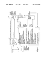
- FIGS. 2 and 3 illustrate a first embodiment of an MPEG on-screen display coder in accordance with the present invention
- FIGS. 4 and 5 illustrate a second embodiment of an MPEG on-screen display coder in accordance with the present invention
- FIGS. 6 and 7 illustrate a third embodiment of an MPEG on-screen display coder in accordance with the present invention
- FIGS. 8 and 9 illustrate a fourth embodiment of an MPEG on-screen display coder in accordance with the present invention.
- FIG. 10 illustrates yet another embodiment of an MPEG on-screen display coder in accordance with the present invention.
- MPEG on-screen display coders are described below. As shown in FIG. 1 , these coders are generally represented by the reference numeral 10 and process an input MPEG-2 transport stream containing transport packets for a selected MPEG encoded video program. This selected MPEG encoded video program may be multiplexed with other programs and/or services generally referred to herein as other programs or as non-selected programs.
- the input MPEG transport stream is usually received from a set top box, a digital tape or disc player, or another device for which an MPEG on-screen display coder provides the capability of on-screen display.
- the input MPEG transport stream is processed by the MPEG on-screen display coder 10 so that an on-screen display appears on the screen of a digital television that is used to view the video program.
- the output of the MPEG on-screen display coder 10 comprises the original intact transport stream.
- the output of the MPEG on-screen display coder 10 comprises a transport stream in which the transport packets containing the selected MPEG encoded video have been deleted and replaced by packets containing locally generated MPEG video as selected by the user or as automatically generated by a host device.
- the output of the MPEG on-screen display coder 10 is intended to be supplied, for example, to either an ATSC VSB modulator (such as may be contained in a VCR) which feeds a digital television or directly to the digital television by way of a baseband interface such as an IEEE 1394 baseband interface.
- the locally generated MPEG video comprises either a static colored background overlaid with on-screen display graphics generated by closed caption data (disclosed below in the section designated Level 1), or alternatively a background derived from the original video overlaid with on-screen display graphics where the graphics are directly encoded into the video (disclosed below in the section designated Level 2).
- the turn on and turn-off of the locally generated MPEG on-screen display video can be controlled automatically or manually by the user.
- the transport stream processing generally described above must be done in such a way that the digital television's MPEG video decoder behaves well in response to the turn on and turn off of the locally generated video.
- the digital television's MPEG video decoder can be made to behave well in response to the turn on and turn off of the locally generated video.
- Size of an encoded frame refers to the amount of data in an encoded frame, not the spatial dimensions of the video frame.
- This MPEG on-screen display coder utilizes an MPEG downsampling decoder to create a small video window overlaid on the full screen on-screen display graphics.
- the Advanced Television Closed Captioning standard (EIA-IS 708) is utilized.
- This standard provides for the insertion of encoded closed caption data into the MPEG-2 compressed video data stream at the picture layer level.
- This standard provides for the periodic insertion of additional Program Map Table (PMT) packets into the data stream in order to provide a service descriptor.
- PMT packets are provided in the MPEG standard as a means of identifying the various data packets, such as video, audio, and closed caption packets, that belong to a program.
- the service descriptor includes a language code and other service attributes for the closed caption data.
- a Level 1 MPEG on-screen display coder basically operates by removing all of the original video packets for the selected video program from the input MPEG transport stream. Packets of data for other non-selected programs that may be present in the transport stream may be left intact or may be modified by the same techniques to be described below, as needed for a particular application. Then, a simplified MPEG video encoder encodes a series of frames comprising a solid colored background with the addition of closed caption data in order to create an on-screen display selected by the user or by automatic operation of the set-top box or other host device. This locally encoded MPEG video is placed into transport packets and these packets are multiplexed into the transport stream at the locations vacated by the original data packets which have been deleted.
- Level 1a the locally generated MPEG video has a time base that is completely independent of that of the original video that was deleted.
- Level 1b the locally generated MPEG video is effectively slaved to the timing of the original video that was deleted.
- Level 1a requires that the MPEG decoder in the digital television receiver be well-behaved under conditions of buffer underflow.
- Level 1b is more generally applicable to a wide range of decoders.
- FIG. 2 shows an MPEG on-screen display coder 12 as a first embodiment of the MPEG on-screen display coder 10 .
- the transport stream is received such as from a set-top box and is fed to a demultiplexer 14 of the MPEG on-screen display coder 12 .
- the demultiplexer 14 extracts only the transport packets for a video program selected manually by a user or selected automatically.
- the output of the demultiplexer 14 is fed to an encoder 16 .
- the transport stream is also fed to a delay buffer 18 which imparts a delay time to the transport stream that is greater than or equal to the processing time of the encoder 16 .
- the delay buffer 18 can detect a transport packet that contains the start of an I frame, and signal the start of the I frame to an on-screen display turn on/off sync block 20 by way of a video I frame marker.
- the delay buffer 18 also outputs the transport stream to an input A of a multiplexer 22 .
- the delay buffer 18 sends a control signal to an override input of the multiplexer 22 (one of two multiplexer control lines) in order to indicate whether each transport packet is a video packet of the selected program.
- the encoder 16 shown in FIG. 2 and in more detail in FIG. 3 , contains an MPEG decoder 24 and an MPEG encode engine 26 .
- the MPEG decoder 24 partially decodes the original selected video in order to determine the number of frames that is currently resident in the digital television's decoder buffer.
- the digital television's decoder buffer can easily be modeled in the MPEG decoder 24 using well known methods explained in the MPEG standard.
- the MPEG decoder 24 within the encoder 16 determines the fullness of the digital television's decoder buffer in order to wait enough time (which may be referred to as the video hold off time) for the digital television's decoder buffer to empty, then the MPEG decoder 24 starts the MPEG encode engine 26 .
- the video hold off time is needed, as explained below, to properly turn on the on-screen display without risking overflow of the digital television's decoder buffer.
- the MPEG encode engine 26 in response to the start instruction from the MPEG decoder 24 , generates a series of transport packets containing MPEG encoded solid color backgrounds along with picture level closed caption data encoded to provide the desired on-screen display as selected by the user or automatically.
- the first frame is an I frame and is followed by a series of P frames.
- the first generated P frame can be perfectly predicted from the generated I frame, and any subsequent P frames can each be perfectly predicted from its preceding P frame by setting all residuals and motion vectors equal to zero.
- the locally encoded video has its own time base (the locally generated program clock reference, PCR, and presentation time stamp, PTS) independent from the time base of the original deleted video.
- the MPEG video layer encoding of the solid color background I frame and subsequent P frames (all of these P frames are identical) can be simplified by storing in ROM only two fully compressed frames (the I frame and one P frame), which are already encoded at a theoretically minimum size. Groups of frames each comprising the I frame followed by a predetermined number of iterations of the P frame are repeatedly output during the interval of on-screen display.
- the MPEG encode engine 26 puts this generated video into on-screen display transport packets and feeds an on-screen display packet buffer 28 from which these on-screen display transport packets are read by the multiplexer 22 at an input C when needed.
- the MPEG encode engine 26 models the activity of the digital television's decoder buffer as discussed above so that the MPEG encode engine 26 is always aware of the number of on-screen display frames in the digital television's decoder buffer.
- the number of on-screen display frames in the digital television's decoder buffer is used by the MPEG encode engine 26 to calculate an on-screen display hold off time which is the amount of time it would take the digital television's decoder buffer to empty if no more on-screen display video packets were sent.
- the on-screen display hold off time is used, as explained below, to properly turn off the on-screen display and return to original video without risking overflow of the digital television's decoder buffer.
- the on-screen display hold off time is fed to the on-screen display turn on/off sync block 20 .
- the first PCR packet generated by the MPEG encode engine 26 after an on-screen display turn on is requested by the user or generated automatically has its PCR discontinuity bit set to tell the digital television's decoder that the time base is changing.
- the multiplexer 22 multiplexes the original transport stream at the input A with null packets and Program Map Table packets at an input B and on-screen display transport packets at the input C.
- the null packets and Program Map Table packets are supplied by a memory 30
- the on-screen display transport packets are supplied by the encoder 16 .
- a multiplexer control input from the on-screen display turn on/off sync block 20 selects the input C.
- the multiplexer 22 reads on-screen display packets from the on-screen display packet buffer 28 of the encoder 16 . If the on-screen display packet buffer 28 is empty, the multiplexer 22 automatically selects the input B and thus reads null packets (or an occasional Program Map Table packet) from the memory 30 .
- the delay buffer 18 provides an override signal to the multiplexer 22 if the transport packet to be output by the delay buffer 18 is not a video packet for the selected program (because the transport packet currently being output by the delay buffer 18 , for example, is an audio packet, a video packet from another program, or some other data packet that is desirable to retain).
- the override signal from the delay buffer 16 forces the multiplexer 22 to select the input A.
- the MPEG on-screen display coder 12 passes all original transport packets except those of the selected video program which are replaced by on-screen display packets, null packets, and Program Map Table packets. If the on-screen display is turned off, the multiplexer 22 always connects the input A to its output.
- FIG. 4 shows an MPEG on-screen display coder 50 as a second embodiment of the MPEG on-screen display coder 10 .
- the transport stream is received such as from a set-top box and is fed to a demultiplexer 52 of the MPEG on-screen display coder 50 .
- the demultiplexer 52 extracts only the transport packets for a video program selected manually by a user or selected automatically.
- the output of the demultiplexer 52 is fed to an encoder 54 .
- the transport stream is also fed to a delay buffer 56 which imparts a constant delay time to the transport stream that is equal to the processing time of the encoder 54 .
- the delay buffer 56 outputs the transport stream to an input A of a multiplexer 58 .
- the delay buffer 56 also sends a control signal to a multiplexer override input of the multiplexer 58 (one of two multiplexer control lines) in order to indicate whether each transport packet is a video packet of the selected program.
- the encoder 54 shown in FIG. 4 and in more detail in FIG. 5 , generates a series of transport packets containing MPEG encoded solid color backgrounds along with picture level closed caption data encoded to provide the desired on-screen display as selected by the user or generated automatically. This data may be referred to herein as on-screen display transport packets.
- a parser 60 of the encoder 54 detects the next I frame which is followed by a series of P frames to be encoded at either a theoretically minimum size, or in a manner constrained by the number of bits in the deleted original video frame, so that the size of the locally generated MPEG video frame is smaller than or equal to the size of the original deleted video frame.
- the first generated P frame can be perfectly predicted from the generated I frame, and any subsequent P frames can each be perfectly predicted from its preceding P frame by setting all residuals and motion vectors equal to zero.
- the MPEG video layer encoding of the solid color background I frame and subsequent P frames can be simplified by storing in ROM only two fully compressed frames (the I frame and one P frame), which are already encoded at a theoretically minimum size. Groups of frames each comprising the I frame followed by a predetermined number of iterations of the P frame are repeatedly output during the interval of on-screen display.
- the time base (PCR/PTS) from the original deleted video is transferred to the locally generated video. It should be noted that any decoding time stamps (DTS's) can be ignored because the encoder 54 in the MPEG on-screen display coder 50 does not encode any B frames.
- Each deleted original video transport packet is replaced by a locally generated video transport packet. If the deleted original video transport packet is also a PCR packet, the PCR value is transferred to the replacement packet.
- the locally encoded video has its own time base generated from the original deleted video as described below. Every deleted packetized elementary stream (PES) packet (video frame) is replaced by a corresponding locally generated PES packet (video frame) with the same PTS.
- PES packetized elementary stream
- Each locally generated replacement encoded frame has the same size (same number of bits) or a smaller size as the original frame it replaces. Null packets and Program Map Table packets are added to each replacement frame so that there are effectively the same number of transport packets in each replacement frame as in its corresponding original frame.
- the encoder 54 includes the parser 60 that parses the original video packets in order to provide the illustrated outputs. An entire frame must be parsed to provide these outputs.
- a frame sync signal is sent to an MPEG encode engine 62 causing it to encode an on-screen display frame If an on-screen display turn on has just been requested, then an I frame is generated, otherwise a P frame is generated. If an I frame is generated, an on-screen display I frame marker (OIF) is signaled on the VIF,OIF signals line and is propagated through the system as shown for later use. The on-screen display I frame marker is not used within the encoder 54 .
- OF on-screen display I frame marker
- a video I frame marker (VIF) from the parser 60 indicates whether the original video frame just parsed is an I frame.
- the video I frame marker is also not used within the encoder 54 , but is propagated through the system for later use.
- the MPEG encode engine 62 may optionally use a format signal to match the on-screen display frame format to that of the original video.
- the output of the MPEG encode engine 62 comprises MPEG video data, the video I frame marker, and the on-screen display I frame marker.
- the MPEG encode engine 62 feeds a PES packetizer 64 which accepts an MPEG video frame from the MPEG encode engine 62 and forms a PES packet using the PTS from the original video PES packet as supplied by the parser 60 .
- the PES packet is fed to a transport packetizer 66 which chops the PES packet into smaller pieces and creates a series of transport packets. If any transport packets for the original video frame are PCR packets, the parser 60 signals which packets in the sequence of packets are PCR packets and also signals the corresponding PCR values of the PCR packets. This information is used by the transport packetizer 66 to create PCR packets that mirror the original PCR packets that were deleted.
- the on-screen display transport packets for this frame are fed to an input A of an on-screen display multiplexer 68 .
- the number of transport packets in the original video frame is fed by the parser 60 to the control input of the on-screen display multiplexer 68 .
- the on-screen display multiplexer 68 outputs the on-screen display transport packets. If the number of on-screen transport packets in the locally generated frame is less than the number of packets in the deleted original frame, the on-screen display multiplexer 68 makes up the difference by selecting input C of the on-screen display multiplexer 68 (null packets) or occasionally input B of the on-screen display multiplexer 68 (Program Map Table packets).
- the encoder 54 sends the on-screen display packets and any required null packets and Program Map Table packets to the input B of the multiplexer 58 of FIG. 4 .
- Both I frame markers are fed to an on-screen display turn on/off sync block 70 .
- the on-screen display turn on/off sync block 70 also receives from the user (or automatically) a signal requesting on-screen display turn on or turn off.
- the on-screen display turn on/off sync block 70 waits for the on-screen display I frame marker to become active.
- the on-screen display turn on/off sync block 70 signals the multiplexer 58 to switch to input B.
- the on-screen display turn on/off sync block 70 again waits for the video I frame marker to become active.
- the on-screen display turn on/off sync block 70 signals the multiplexer 58 to switch to input A. It should be noted that the override control input to the multiplexer 58 operates the same as for Level 1a. The hold off times of Level 1a need not be considered in Level 1b because the video time base in Level 1b never changes. The digital television's decoder buffer will not overflow because every replacement frame is smaller that its corresponding deleted original frame.
- a Level 2 MPEG on-screen display coder differs from a Level 1 MPEG on-screen display coder in that closed caption data is not used to create the on-screen display graphics.
- the graphics are instead generated automatically or in response to user selection by creating pixel data and overlaying it on the incoming original MPEG video. This combination of original video and overlaid graphics are encoded as MPEG video.
- a Level 2a MPEG on-screen display coder basically operates by deleting from the input MPEG transport stream all the original video packets in the P and B frames of the selected video program. The I frames of the selected video program are passed through unchanged. Then, a simplified MPEG video encoder first encodes a P frame predicted from the preceding I frame, with the residuals in the predicted P frame consisting of the overlaid graphics. Each subsequent P frame is perfectly predicted from the previous P frame with the residuals and the motion vectors set equal to zero. These P frames replace the deleted original P and B frames. As in level 1 b , the locally generated video is effectively slaved to the timing of the original deleted video.
- the I frames have no overlaid graphics, which may in some case cause a visible flicker.
- This problem is solved in Level 2b.
- the incoming original I frames are partially decoded and overlaid with the graphics selected by the user or automatically.
- the I frame is then re-encoded with the same quantization, VLC table, and DCT coefficient selection as the original I frame. In this way, the number of bits in the overlaid I frame matches the number of bits in the original I frame.
- the incoming P and B frames are deleted and replaced by locally generated P frames that are perfectly predicted from the locally generated previous frame with the residuals and the motion vectors set equal to zero.
- the Level 2a MPEG on-screen display coder as shown in FIG. 6 is very similar to the Level 1b MPEG on-screen display coder as shown in FIG. 4 .
- the control and synchronization of the on-screen display turn on/off sync blocks and the multiplexers are nearly identical.
- the principal difference is that the video I frame marker in the Level 2a implementation serves the purpose of both the video I frame marker and the on-screen display I frame marker of the Level 1b implementation because the I frames for both the original video and the on-screen display always coincide, so that a separate on-screen display I frame marker is not needed.
- FIG. 6 shows an MPEG on-screen display coder 80 as a third embodiment of the MPEG on-screen display coder 10 .
- the transport stream is received such as from a set-top box and is fed to a demultiplexer 82 of the MPEG on-screen display coder 80 .
- the demultiplexer 82 extracts only the transport packets for a video program selected manually by a user or selected automatically.
- the output of the demultiplexer 82 is fed to an encoder 84 .
- the transport stream is also fed to a delay buffer 86 which imparts a constant delay time to the transport stream that is equal to the processing time of the encoder 84 .
- the delay buffer 86 outputs the transport stream to an input A of a multiplexer 88 .
- the delay buffer 86 also sends a control signal to a multiplexer override input of the multiplexer 88 (one of two multiplexer control lines) in order to indicate whether each transport packet is a video packet of the selected program.
- the encoder 84 sends a video I frame marker to an on-screen display turn on/off sync block 89 .
- the on-screen display turn on/off sync block 89 also receives from the user (or automatically) a signal requesting on-screen display turn on or turn off.
- the on-screen display turn on/off sync block 89 waits for the video I frame marker to become active. Then, the on-screen display turn on/off sync block 89 signals the multiplexer 88 to switch to an input B.
- the on-screen display turn on/off sync block 89 waits for the video I frame marker to become active. Then, the on-screen display turn on/off sync block 89 signals the multiplexer 88 to switch to an input A.
- the encoder 84 passes the original I frames through unchanged. When an on-screen display is requested by the user or automatically, the encoder 84 continues to pass the original I frames unchanged.
- the first P frame after the first I frame following the on-screen display turn on has the selected graphics encoded by predicting the P frame from the previous I frame with the graphics encoded as the residuals and with the motion vectors set equal to zero. Subsequent P frames are predicted from previous P frames with the residuals and the motion vectors set equal to zero. Every replacement frame is less than or equal to the size of the original frame it replaces.
- the processing time of the encoder 84 is the same as that of the delay buffer 86 .
- the method of transferring the original PCR/PTS information to the locally generated MPEG video is the same as for Level 1b. Therefore, all timing is slaved to the original video (as in Level 1b).
- a parser 90 (see FIG. 7 ) of the encoder 84 passes I frame transport packets unchanged to an MPEG encode engine 92 along with a video I frame marker.
- the MPEG encode engine 92 encodes the P frames as previously explained. Each P frame is made into a PES packet by a PES packetizer 94 .
- the P frame PES packet is divided into a series of transport packets by a transport packetizer 96 .
- the P frame transport packets are fed to an input A of an on-screen display multiplexer 98 .
- a null packet source 100 feeds null packets to an input B of the on-screen display multiplexer 98 .
- the number of transport packets in the original deleted video (P or B) frame is fed to the control input of the on-screen display multiplexer 98 by the parser 90 .
- the on-screen display multiplexer 98 outputs the P frame transport packets. If the number of P frame transport packets in the locally generated P frame is less than the number of packets in the deleted original frame, the on-screen display multiplexer 98 makes up the difference by selecting the input B in order to fill in with null packets.
- I frame transport packets output by the MPEG encode engine 92 are fed to an I frame delay block 102 which matches the delay times of the PES packetizer 94 and the transport packetizer 96 .
- the video I frame marker is propagated along with the I frame packets.
- the video I frame marker is fed to the override of the on-screen display multiplexer 98 in order to switch the input C to the output of the on-screen display multiplexer 98 .
- the Level 2b MPEG on-screen display coder as shown in FIG. 8 is nearly identical to the Level 2a MPEG on-screen display coder as shown in FIG. 6 . except that the encoder of the Level 2b MPEG on-screen display coder does not pass the I frame transport packets through unchanged.
- the I frames are decoded, then overlaid with graphics and re-encoded as MPEG video.
- the next locally generated frame (a P frame) is perfectly predicted from the I frame. Subsequent P frames are perfectly predicted from the previous P frame.
- FIG. 8 shows an MPEG on-screen display coder 110 as a fourth embodiment of the MPEG on-screen display coder 10 .
- the transport stream is received such as from a set-top box and is fed to a demultiplexer 112 of the MPEG on-screen display coder 110 .
- the demultiplexer 112 extracts only the transport packets for a video program selected manually by a user or selected automatically.
- the output of the demultiplexer 112 is fed to an encoder 114 .
- the transport stream is also fed to a delay buffer 116 which imparts a constant delay time to the transport stream that is equal to the processing time of the encoder 114 .
- the delay buffer 116 outputs the transport stream to an input A of a multiplexer 118 .
- the delay buffer 116 also sends a control signal to a multiplexer override input of the multiplexer 118 (one of two multiplexer control lines) in order to indicate whether each transport packet is a video packet of the selected program.
- the encoder 114 sends a video I frame marker to an on-screen display turn on/off sync block 120 .
- the on-screen display turn on/off sync block 120 also receives from the user (or automatically) a signal requesting an on-screen display turn on or off.
- the on-screen display turn on/off sync block- 120 waits for the video I frame marker to become active. Then, the on-screen display turn on/off sync block 120 signals the multiplexer 118 to switch to an input B.
- the on-screen display turn on/off sync block 120 waits for the video I frame marker to become active. Then, the on-screen display turn on/off sync block 120 signals the multiplexer 118 to switch to the input A.
- the encoder 114 shown in FIG. 8 and in more detail in FIG. 9 is similar to the encoder 84 shown in FIG. 7 and differs in that an MPEG encode engine 122 receives I frames decoded by a parser 124 and outputs locally encoded I and P frames on a single line (“video data”). Thus, there is no separate line for the I frames and there is no I frame delay block.
- the incoming decoded original I frames are overlaid with the user selected or automatically generated graphics. The I is then re-encoded by the MPEG encode engine 122 with the same quantization, VLC table, and DCT coefficient selection as the original I frame.
- the number of bits in the overlaid I frame matches the number of bits in the original I frame.
- the incoming P and B frames are deleted and are replaced by locally generated P frames that are perfectly predicted from the locally generated previous frame with residuals and motion vectors set equal to zero. All generated P frames are less than or equal in size to the corresponding deleted original frames. This size equalization is achieved by encoding in a manner that is constrained by the number of bits in the deleted frame, or encoding a theoretical minimum size perfectly predicted frame.
- the encoder 114 includes a PES packetizer 126 , a transport packetizer 128 , and an on-screen display multiplexer 130 that operate in the same manner as the PES packetizer 94 , the transport packetizer 96 , and the on-screen display multiplexer 98 of FIG. 7 except that the on-screen display multiplexer 130 has no input C.
- a potential problem occurs as a result of the encoder 114 changing the I frame. If the on-screen display is initially turned off, the final B frame (or frames) of the previous GOP (group of pictures) may use a subsequent I frame in the next GOP for prediction. If an on-screen display turn on is then requested just as this I frame arrives, this I frame will be modified by the graphics overlay. Then, the final B frames(s) of the video without the overlay will not have the expected reference (the subsequent I frame has been modified) for prediction in the decoder of the digital television and will therefore be displayed with errors.
- a simple solution for the Level 2b MPEG on-screen display coder 110 is to use the Level 2a method for the first GOP after an on-screen display turn on has been requested. In this way, the first original I frame is not altered. Subsequent to the first GOP, the Level 2b method is used.
- transport layer video packets for I frames are deleted and replaced by locally generated I frames consisting of a solid color background and the desired on-screen display (the original video is not visible as a background). This encoding is constrained by the frame size of the deleted original I frame.
- Transport layer video packets for B and P frames are also deleted. These frames are replaced by locally generated P frames. The first P frame is predicted from the I frame with the residuals set to zero. Subsequent P frames are predicted from the preceding P frame with the residuals set to zero.
- Level 2 (a and b) encodes with all motion vectors equal to zero. In that case, any graphics animation can only occur at the I frame rate.
- a somewhat more complex encoder could be used that uses non-zero motion vectors for the P frames to efficiently encode animated graphics that can change at the frame rate. Any such encoding would be constrained by the number of bits in each replaced frame.
- the on-screen display turn on may be selected.
- the encoder in the MPEG on-screen display coder passes the next I frame through without modification. Subsequently received P frames for this GOP are deleted. The encoder substitutes a first P frame that is perfectly predicted from the I frame. Subsequent P frames are perfectly predicted from preceding P frames. These operations will have the effect of lowering the buffer occupancy in the digital television receiver. Then, the next I frame can be decoded, overlaid with graphics, and re-encoded. The number of bits allocated to this overlaid I frame can be relatively large, governed by the amount of space in the digital television's decoder buffer as indicated by the buffer occupancy model. As an alternative to overlaying graphics on the original video in the I frame, selected macroblocks of the original video may be deleted and replaced with intra coded graphics macroblocks.
- the “freeze” can last for more than one GOP so as to open up even more space in the digital television's decoder buffer.
- This method continuously displays the original video in a subsampled manner as a small window on top of full screen displays.
- the original MPEG video is decoded, subsampled, and squeezed down to a small size.
- These operations can be done with a standard MPEG decoder followed by filtering and downsampling or alternatively can be achieved with a modified lower cost MPEG decoder that directly produces a downsampled image (referred to as MPEG downconversion or all format decoding according to several published methods).
- MPEG downconversion or all format decoding referred to as MPEG downconversion or all format decoding according to several published methods.
- MPEG downconversion or all format decoding referred to as MPEG downconversion or all format decoding according to several published methods.
- this downsampled image is placed on top or transparently mixed with the desired on-screen display.
- This combination is then MPEG encoded.
- the encoding is constrained by the number of bits in the original video frames. This encoding should be achievable because the
- Locally generated I, P, and B frames respectively replace original I, P, and B frames.
- the time base (PCR/PTS) of the original video is transferred to the locally generated video as in Level 2.
- Each locally generated frame is less than or equal to the size of the frame it replaces with any difference made up in null transport packets as explained in the previous methods.
- a simplified encoder could be used that replaces P and B frames with only P frames and also encodes with motion vectors always set equal to zero (without motion compensation).
- an MPEG decoder and downsampler 140 decodes the incoming MPEG video.
- the timing, frame size, and type information is extracted (as in Level 2) and sent to an MPEG encoder 142 .
- the decoded video is downsampled (this downsampling can optionally be inherent in the decoding process) and arranged to be displayed as a small window.
- this window is overlaid on top of the locally generated screen graphics.
- the locally generated screen graphics overlaid with the small window is then fed to the MPEG encoder 144 which encodes the video as described above, constrained by the timing and frame data from the decoder.
- Level 2 can be used with a solid color background encoded with the on-screen display and the features of Level 1 can be used with the on-screen display overlaid on video.
Abstract
Description
Claims (43)
Priority Applications (1)
| Application Number | Priority Date | Filing Date | Title |
|---|---|---|---|
| US09/330,769 US7327790B1 (en) | 1998-06-16 | 1999-06-11 | MPEG on screen display coder for DTV interfaces |
Applications Claiming Priority (2)
| Application Number | Priority Date | Filing Date | Title |
|---|---|---|---|
| US8948298P | 1998-06-16 | 1998-06-16 | |
| US09/330,769 US7327790B1 (en) | 1998-06-16 | 1999-06-11 | MPEG on screen display coder for DTV interfaces |
Publications (1)
| Publication Number | Publication Date |
|---|---|
| US7327790B1 true US7327790B1 (en) | 2008-02-05 |
Family
ID=38988857
Family Applications (1)
| Application Number | Title | Priority Date | Filing Date |
|---|---|---|---|
| US09/330,769 Expired - Fee Related US7327790B1 (en) | 1998-06-16 | 1999-06-11 | MPEG on screen display coder for DTV interfaces |
Country Status (1)
| Country | Link |
|---|---|
| US (1) | US7327790B1 (en) |
Cited By (14)
| Publication number | Priority date | Publication date | Assignee | Title |
|---|---|---|---|---|
| US20020198905A1 (en) * | 2001-05-29 | 2002-12-26 | Ali Tabatabai | Transport hint table for synchronizing delivery time between multimedia content and multimedia content descriptions |
| US20040196905A1 (en) * | 2003-04-04 | 2004-10-07 | Sony Corporation And Sony Electronics Inc. | Apparatus and method of parallel processing an MPEG-4 data stream |
| US20050069040A1 (en) * | 2001-12-19 | 2005-03-31 | Edouard Francois | Method and device for compressing video-packet coded video data |
| US20060268163A1 (en) * | 2005-05-27 | 2006-11-30 | Canon Kabushiki Kaisha | Digital Television Broadcasting Receiving Apparatus, Control Method for Digital Television Broadcasting Receiving Apparatus, and Control Program for the Same |
| US20070132784A1 (en) * | 1999-09-03 | 2007-06-14 | Equator Technologies, Inc. | Circuit and method for modifying a region of an encoded image |
| US20080036695A1 (en) * | 2006-08-09 | 2008-02-14 | Kabushiki Kaisha Toshiba | Image display device, image display method and computer readable medium |
| US20090059068A1 (en) * | 2005-09-30 | 2009-03-05 | Toshiharu Hanaoka | Image display device and method |
| US20090164652A1 (en) * | 2007-12-21 | 2009-06-25 | General Instrument Corporation | Methods and System for Processing Time-Based Content |
| US20100150182A1 (en) * | 2008-12-12 | 2010-06-17 | Tandberg Television Inc. | Systems and methods for mutiplexing mpeg services for ip networks |
| US20100165194A1 (en) * | 2008-12-29 | 2010-07-01 | General Instrument Corporation | Capture buffer control methodology for caption carriage switch |
| US20120159530A1 (en) * | 2010-12-16 | 2012-06-21 | Cisco Technology, Inc. | Micro-Filtering of Streaming Entertainment Content Based on Parental Control Setting |
| US20130222691A1 (en) * | 2003-09-17 | 2013-08-29 | Lg Electronics Inc | Digital broadcast receiver and method for processing caption thereof |
| US20140226729A1 (en) * | 2005-02-15 | 2014-08-14 | Sony Corporation | Digital closed caption transport in standalone stream |
| US9456243B1 (en) | 2003-06-06 | 2016-09-27 | Arris Enterprises, Inc. | Methods and apparatus for processing time-based content |
Citations (7)
| Publication number | Priority date | Publication date | Assignee | Title |
|---|---|---|---|---|
| US5650825A (en) * | 1995-03-31 | 1997-07-22 | Matsushita Electric Corporation Of America | Method and apparatus for sending private data instead of stuffing bits in an MPEG bit stream |
| US5894320A (en) * | 1996-05-29 | 1999-04-13 | General Instrument Corporation | Multi-channel television system with viewer-selectable video and audio |
| US5917830A (en) * | 1996-10-18 | 1999-06-29 | General Instrument Corporation | Splicing compressed packetized digital video streams |
| US6005629A (en) * | 1996-05-29 | 1999-12-21 | Sgs-Thomson Microelectronics S.A. | System for converting digital television signals with insertion of interactive menus |
| US6078328A (en) * | 1998-06-08 | 2000-06-20 | Digital Video Express, Lp | Compressed video graphics system and methodology |
| US6115080A (en) * | 1998-06-05 | 2000-09-05 | Sarnoff Corporation | Channel selection methodology in an ATSC/NTSC television receiver |
| US6758540B1 (en) * | 1998-12-21 | 2004-07-06 | Thomson Licensing S.A. | Method and apparatus for providing OSD data for OSD display in a video signal having an enclosed format |
-
1999
- 1999-06-11 US US09/330,769 patent/US7327790B1/en not_active Expired - Fee Related
Patent Citations (7)
| Publication number | Priority date | Publication date | Assignee | Title |
|---|---|---|---|---|
| US5650825A (en) * | 1995-03-31 | 1997-07-22 | Matsushita Electric Corporation Of America | Method and apparatus for sending private data instead of stuffing bits in an MPEG bit stream |
| US5894320A (en) * | 1996-05-29 | 1999-04-13 | General Instrument Corporation | Multi-channel television system with viewer-selectable video and audio |
| US6005629A (en) * | 1996-05-29 | 1999-12-21 | Sgs-Thomson Microelectronics S.A. | System for converting digital television signals with insertion of interactive menus |
| US5917830A (en) * | 1996-10-18 | 1999-06-29 | General Instrument Corporation | Splicing compressed packetized digital video streams |
| US6115080A (en) * | 1998-06-05 | 2000-09-05 | Sarnoff Corporation | Channel selection methodology in an ATSC/NTSC television receiver |
| US6078328A (en) * | 1998-06-08 | 2000-06-20 | Digital Video Express, Lp | Compressed video graphics system and methodology |
| US6758540B1 (en) * | 1998-12-21 | 2004-07-06 | Thomson Licensing S.A. | Method and apparatus for providing OSD data for OSD display in a video signal having an enclosed format |
Cited By (55)
| Publication number | Priority date | Publication date | Assignee | Title |
|---|---|---|---|---|
| US20070132784A1 (en) * | 1999-09-03 | 2007-06-14 | Equator Technologies, Inc. | Circuit and method for modifying a region of an encoded image |
| US20020198905A1 (en) * | 2001-05-29 | 2002-12-26 | Ali Tabatabai | Transport hint table for synchronizing delivery time between multimedia content and multimedia content descriptions |
| US7734997B2 (en) * | 2001-05-29 | 2010-06-08 | Sony Corporation | Transport hint table for synchronizing delivery time between multimedia content and multimedia content descriptions |
| US20050069040A1 (en) * | 2001-12-19 | 2005-03-31 | Edouard Francois | Method and device for compressing video-packet coded video data |
| US8811498B2 (en) * | 2001-12-19 | 2014-08-19 | Thomson Licensing S.A. | Method and device for compressing video-packet coded video data |
| US7660352B2 (en) * | 2003-04-04 | 2010-02-09 | Sony Corporation | Apparatus and method of parallel processing an MPEG-4 data stream |
| US20040196905A1 (en) * | 2003-04-04 | 2004-10-07 | Sony Corporation And Sony Electronics Inc. | Apparatus and method of parallel processing an MPEG-4 data stream |
| US9456243B1 (en) | 2003-06-06 | 2016-09-27 | Arris Enterprises, Inc. | Methods and apparatus for processing time-based content |
| US9001273B2 (en) | 2003-09-17 | 2015-04-07 | Lg Electronics Inc. | Digital broadcast receiver and method for processing caption thereof |
| US8817180B2 (en) | 2003-09-17 | 2014-08-26 | Lg Electronics Inc. | Digital broadcast receiver and method for processing caption thereof |
| US9756367B2 (en) | 2003-09-17 | 2017-09-05 | Lg Electronics Inc. | Digital broadcast receiver and method for processing caption thereof |
| US9602755B2 (en) | 2003-09-17 | 2017-03-21 | Lg Electronics Inc. | Digital broadcast receiver and method for processing caption thereof |
| US9456166B2 (en) | 2003-09-17 | 2016-09-27 | Lg Electronics Inc. | Digital broadcast receiver and method for processing caption thereof |
| US9445035B2 (en) | 2003-09-17 | 2016-09-13 | Lg Electronics Inc. | Digital broadcast receiver and method for processing caption thereof |
| US20130222691A1 (en) * | 2003-09-17 | 2013-08-29 | Lg Electronics Inc | Digital broadcast receiver and method for processing caption thereof |
| US8711283B2 (en) | 2003-09-17 | 2014-04-29 | Lg Electronics Inc. | Digital broadcast receiver and method for processing caption thereof |
| US8711282B2 (en) | 2003-09-17 | 2014-04-29 | Lg Electronics Inc. | Digital broadcast receiver and method for processing caption thereof |
| US8711281B2 (en) | 2003-09-17 | 2014-04-29 | Lg Electronics Inc. | Digital broadcast receiver and method for processing caption thereof |
| US8743283B2 (en) | 2003-09-17 | 2014-06-03 | Lg Electronics Inc. | Digital broadcast receiver and method for processing caption thereof |
| US8743282B2 (en) | 2003-09-17 | 2014-06-03 | Lg Electronics Inc. | Digital broadcast receiver and method for processing caption thereof |
| US8749705B2 (en) | 2003-09-17 | 2014-06-10 | Lg Electronics Inc. | Digital broadcast receiver and method for processing caption thereof |
| US8754986B2 (en) | 2003-09-17 | 2014-06-17 | Lg Electronics Inc. | Digital broadcast receiver and method for processing caption thereof |
| US8754985B2 (en) | 2003-09-17 | 2014-06-17 | Lg Electronics Inc. | Digital broadcast receiver and method for processing caption thereof |
| US8760576B2 (en) | 2003-09-17 | 2014-06-24 | Lg Electronics Inc. | Digital broadcast receiver and method for processing caption thereof |
| US8780268B2 (en) | 2003-09-17 | 2014-07-15 | Lg Electronics Inc. | Digital broadcast receiver and method for processing caption thereof |
| US8786777B2 (en) | 2003-09-17 | 2014-07-22 | Lg Electronics Inc. | Digital broadcast receiver and method for processing caption thereof |
| US8792055B2 (en) * | 2003-09-17 | 2014-07-29 | Lg Electronics Inc. | Digital broadcast receiver and method for processing caption thereof |
| US8797459B2 (en) | 2003-09-17 | 2014-08-05 | Lg Electronics Inc. | Digital broadcast receiver and method for processing caption thereof |
| US9313441B2 (en) | 2003-09-17 | 2016-04-12 | Lg Electronics Inc. | Digital broadcast receiver and method for processing caption thereof |
| US9307180B2 (en) | 2003-09-17 | 2016-04-05 | Lg Electronics Inc. | Digital broadcast receiver and method for processing caption thereof |
| US8817181B2 (en) | 2003-09-17 | 2014-08-26 | Lg Electronics Inc. | Digital broadcast receiver and method for processing caption thereof |
| US9124848B2 (en) | 2003-09-17 | 2015-09-01 | Lg Electronics Inc. | Digital broadcast receiver and method for processing caption thereof |
| US8823874B2 (en) | 2003-09-17 | 2014-09-02 | Lg Electronics Inc. | Digital broadcast receiver and method for processing caption thereof |
| US8830396B2 (en) | 2003-09-17 | 2014-09-09 | Lg Electronics Inc. | Digital broadcast receiver and method for processing caption thereof |
| US8885101B2 (en) | 2003-09-17 | 2014-11-11 | Lg Electronics Inc. | Digital broadcast receiver and method for processing caption thereof |
| US9060154B2 (en) | 2003-09-17 | 2015-06-16 | Lg Electronics Inc. | Digital broadcast receiver and method for processing caption thereof |
| US8988608B2 (en) | 2003-09-17 | 2015-03-24 | Lg Electronics Inc. | Digital broadcast receiver and method for processing caption thereof |
| US8988607B2 (en) | 2003-09-17 | 2015-03-24 | Lg Electronics Inc. | Digital broadcast receiver and method for processing caption thereof |
| US8988606B2 (en) | 2003-09-17 | 2015-03-24 | Lg Electronics Inc. | Digital broadcast receiver and method for processing caption thereof |
| US9060204B2 (en) | 2003-09-17 | 2015-06-16 | Lg Electronics Inc. | Digital broadcast receiver and method for processing caption thereof |
| US9019434B1 (en) | 2003-09-17 | 2015-04-28 | Lg Electronics Inc. | Digital broadcast receiver and method for processing caption thereof |
| US9030608B2 (en) | 2003-09-17 | 2015-05-12 | Lg Electronics Inc. | Digital broadcast receiver and method for processing caption thereof |
| US9049476B1 (en) | 2003-09-17 | 2015-06-02 | Lg Electronics Inc. | Digital broadcast receiver and method for processing caption thereof |
| US20140226729A1 (en) * | 2005-02-15 | 2014-08-14 | Sony Corporation | Digital closed caption transport in standalone stream |
| US9398296B2 (en) * | 2005-02-15 | 2016-07-19 | Sony Corporation | Digital closed caption transport in standalone stream |
| US7847865B2 (en) * | 2005-05-27 | 2010-12-07 | Canon Kabushiki Kaisha | Digital television broadcasting receiving apparatus, control method for digital television broadcasting receiving apparatus, and control program for the same |
| US20060268163A1 (en) * | 2005-05-27 | 2006-11-30 | Canon Kabushiki Kaisha | Digital Television Broadcasting Receiving Apparatus, Control Method for Digital Television Broadcasting Receiving Apparatus, and Control Program for the Same |
| US20090059068A1 (en) * | 2005-09-30 | 2009-03-05 | Toshiharu Hanaoka | Image display device and method |
| US9881535B2 (en) * | 2005-09-30 | 2018-01-30 | Sharp Kabushiki Kaisha | Image display device and method |
| US20080036695A1 (en) * | 2006-08-09 | 2008-02-14 | Kabushiki Kaisha Toshiba | Image display device, image display method and computer readable medium |
| US8966103B2 (en) * | 2007-12-21 | 2015-02-24 | General Instrument Corporation | Methods and system for processing time-based content |
| US20090164652A1 (en) * | 2007-12-21 | 2009-06-25 | General Instrument Corporation | Methods and System for Processing Time-Based Content |
| US20100150182A1 (en) * | 2008-12-12 | 2010-06-17 | Tandberg Television Inc. | Systems and methods for mutiplexing mpeg services for ip networks |
| US20100165194A1 (en) * | 2008-12-29 | 2010-07-01 | General Instrument Corporation | Capture buffer control methodology for caption carriage switch |
| US20120159530A1 (en) * | 2010-12-16 | 2012-06-21 | Cisco Technology, Inc. | Micro-Filtering of Streaming Entertainment Content Based on Parental Control Setting |
Similar Documents
| Publication | Publication Date | Title |
|---|---|---|
| US5633683A (en) | Arrangement and method for transmitting and receiving mosaic video signals including sub-pictures for easy selection of a program to be viewed | |
| CA2370227C (en) | Method and apparatus for compressing video sequences | |
| EP1230800B1 (en) | Method and apparatus for transmitting video and graphics in a compressed form | |
| KR100574186B1 (en) | Encoded stream splicing device and method, and an encoded stream generating device and method | |
| CA2388606C (en) | Picture-in-picture and multiple video streams using slice-based encoding | |
| KR100950867B1 (en) | A method for processing packetized video data, a method fro decoding image data, and a video broadcasting method | |
| US7327790B1 (en) | MPEG on screen display coder for DTV interfaces | |
| US20100296574A1 (en) | Apparatus and method for combining realtime and non-realtime encoded content | |
| JP2002521930A (en) | Method and apparatus for encoding a user interface | |
| US7305173B2 (en) | Decoding device and decoding method | |
| JP2002521928A (en) | Method and apparatus for combining a video sequence with an interactive program guide | |
| WO2008036185A2 (en) | Methods, apparatus, and systems for insertion of overlay content into a video signal with transrating capabilities | |
| US20050015794A1 (en) | Audio/video decoding process and device, and video driver circuit and decoder box incorporating the same | |
| WO1998054902A1 (en) | Method and apparatus for splicing compressed information signals | |
| KR100673253B1 (en) | Apparatus for Video Decoding | |
| US6963611B1 (en) | Process and device for switching digital television programs | |
| JP2002051325A (en) | Digital broadcast image receiver and method therefor | |
| US8224148B2 (en) | Decoding apparatus and decoding method | |
| KR20010063875A (en) | Interactive Broadcast Terminal System | |
| JPH11177921A (en) | Digital data edit method and digital data edit device | |
| O'Grady et al. | Real-time switching of MPEG-2 bitstreams | |
| Peng et al. | Decoding of DVB Digital Television Subtitles | |
| JP2007259195A (en) | Multiplexed stream conversion device and method |
Legal Events
| Date | Code | Title | Description |
|---|---|---|---|
| AS | Assignment |
Owner name: ZENITH ELECTRONICS CORP., ILLINOIS Free format text: ASSIGNMENT OF ASSIGNORS INTEREST;ASSIGNORS:BRETL, WAYNE E.;FIMOFF, MARK;SNOPKO, PAUL A.;REEL/FRAME:010116/0161 Effective date: 19990610 |
|
| AS | Assignment |
Owner name: CITICORP NORTH AMERICA, INC., AS AGENT, NEW YORK Free format text: SECURITY AGREEMENT;ASSIGNOR:ZENITH ELECTRONICS CORPORATION;REEL/FRAME:010470/0414 Effective date: 19991109 |
|
| AS | Assignment |
Owner name: LG ELECTRONICS INC., KOREA, REPUBLIC OF Free format text: SECURITY AGREEMENT;ASSIGNOR:ZENITH ELECTRONICS CORPORATION;REEL/FRAME:010618/0424 Effective date: 19991109 |
|
| AS | Assignment |
Owner name: ZENITH ELECTRONICS CORPORATION, ILLINOIS Free format text: RELEASE OF SECURITY INTEREST;ASSIGNOR:CITICORP NORTH AMERICA, INC.;REEL/FRAME:012188/0204 Effective date: 20010822 |
|
| STCF | Information on status: patent grant |
Free format text: PATENTED CASE |
|
| FPAY | Fee payment |
Year of fee payment: 4 |
|
| FPAY | Fee payment |
Year of fee payment: 8 |
|
| FEPP | Fee payment procedure |
Free format text: MAINTENANCE FEE REMINDER MAILED (ORIGINAL EVENT CODE: REM.); ENTITY STATUS OF PATENT OWNER: LARGE ENTITY |
|
| LAPS | Lapse for failure to pay maintenance fees |
Free format text: PATENT EXPIRED FOR FAILURE TO PAY MAINTENANCE FEES (ORIGINAL EVENT CODE: EXP.); ENTITY STATUS OF PATENT OWNER: LARGE ENTITY |
|
| STCH | Information on status: patent discontinuation |
Free format text: PATENT EXPIRED DUE TO NONPAYMENT OF MAINTENANCE FEES UNDER 37 CFR 1.362 |
|
| FP | Expired due to failure to pay maintenance fee |
Effective date: 20200205 |