US7331493B2 - Simplified two-man lifting harness - Google Patents
Simplified two-man lifting harness Download PDFInfo
- Publication number
- US7331493B2 US7331493B2 US10/845,940 US84594004A US7331493B2 US 7331493 B2 US7331493 B2 US 7331493B2 US 84594004 A US84594004 A US 84594004A US 7331493 B2 US7331493 B2 US 7331493B2
- Authority
- US
- United States
- Prior art keywords
- user
- strap
- central
- loops
- lift
- Prior art date
- Legal status (The legal status is an assumption and is not a legal conclusion. Google has not performed a legal analysis and makes no representation as to the accuracy of the status listed.)
- Active - Reinstated, expires
Links
Images


Classifications
-
- A—HUMAN NECESSITIES
- A45—HAND OR TRAVELLING ARTICLES
- A45F—TRAVELLING OR CAMP EQUIPMENT: SACKS OR PACKS CARRIED ON THE BODY
- A45F3/00—Travelling or camp articles; Sacks or packs carried on the body
- A45F3/14—Carrying-straps; Pack-carrying harnesses
-
- A—HUMAN NECESSITIES
- A44—HABERDASHERY; JEWELLERY
- A44B—BUTTONS, PINS, BUCKLES, SLIDE FASTENERS, OR THE LIKE
- A44B11/00—Buckles; Similar fasteners for interconnecting straps or the like, e.g. for safety belts
- A44B11/02—Buckles; Similar fasteners for interconnecting straps or the like, e.g. for safety belts frictionally engaging surface of straps
- A44B11/06—Buckles; Similar fasteners for interconnecting straps or the like, e.g. for safety belts frictionally engaging surface of straps with clamping devices
- A44B11/08—Buckles; Similar fasteners for interconnecting straps or the like, e.g. for safety belts frictionally engaging surface of straps with clamping devices roller displaceable in wedge-shaped slot
-
- B—PERFORMING OPERATIONS; TRANSPORTING
- B65—CONVEYING; PACKING; STORING; HANDLING THIN OR FILAMENTARY MATERIAL
- B65G—TRANSPORT OR STORAGE DEVICES, e.g. CONVEYORS FOR LOADING OR TIPPING, SHOP CONVEYOR SYSTEMS OR PNEUMATIC TUBE CONVEYORS
- B65G7/00—Devices for assisting manual moving or tilting heavy loads
- B65G7/12—Load carriers, e.g. hooks, slings, harness, gloves, modified for load carrying
-
- A—HUMAN NECESSITIES
- A45—HAND OR TRAVELLING ARTICLES
- A45F—TRAVELLING OR CAMP EQUIPMENT: SACKS OR PACKS CARRIED ON THE BODY
- A45F3/00—Travelling or camp articles; Sacks or packs carried on the body
- A45F3/14—Carrying-straps; Pack-carrying harnesses
- A45F2003/146—Pack-carrying harnesses
-
- Y—GENERAL TAGGING OF NEW TECHNOLOGICAL DEVELOPMENTS; GENERAL TAGGING OF CROSS-SECTIONAL TECHNOLOGIES SPANNING OVER SEVERAL SECTIONS OF THE IPC; TECHNICAL SUBJECTS COVERED BY FORMER USPC CROSS-REFERENCE ART COLLECTIONS [XRACs] AND DIGESTS
- Y10—TECHNICAL SUBJECTS COVERED BY FORMER USPC
- Y10T—TECHNICAL SUBJECTS COVERED BY FORMER US CLASSIFICATION
- Y10T24/00—Buckles, buttons, clasps, etc.
- Y10T24/40—Buckles
- Y10T24/4002—Harness
- Y10T24/4028—Penetrating tongue
- Y10T24/4044—Sliding part or wedge
Definitions
- the present invention relates to a streamlined shoulder harness and lifting strap apparatus suited to allow two or more users to lift large, heavy appliances and the like.
- Inventions which enable two persons to more easily lift and carry heavy objects such as refrigerators, stoves, washer/dryers, large loaded crates and the like, are known in the art. Common construction being such that the weight is suspended from the user's shoulders, leaving their arms and hands free to steady the load. A strap or straps is suspended between each user's shoulder harness, wherein the strap carries the load.
- U.S. Pat. No. 2,431,780 (1947) to Theal discloses a two-person lifting apparatus having a shoulder harness for each user.
- Each shoulder harness pins the user's arms against his ribs while the load is carried by a strap assembly, which is suspended between them. The pinning of the user's arms reduces the efficiency of the user and increases the risk of accidents.
- U.S. Pat. No. 5,009,349 (1991) to Eide et al. discloses a shoulder harness for supporting a pair of straps that carry a load.
- the harness permits free arm movement.
- the two straps required each have metal hoops at each end.
- the hoops hook onto hooks, which are suspended from the shoulder harness.
- the hoops prevent the sliding of the strap under an appliance.
- the system requires access from each side of the appliance to place the straps under the appliance from the side.
- U.S. Pat. No. 6,729,511 (2004) to Dent, III discloses a single, central lifting strap. It is used by professional movers who require the strap size adjustments, the shoulder pad and the flexible modes of operation. A two carabiner attachment assembly supports a wide central tension buckle for each worker. A single wide strap or webbing is suspended between the users to support a load.
- the present invention utilizes the same one central strap, which can be easily slid under an appliance from front to back or side to side.
- a relatively wide tension buckle containing two slots may be suspended from each user via a pair of looped shoulder straps.
- Each of the user's tension buckles supports the end of a relatively wide, flat, web-type strap. This strap may support any load that two users could lift.
- several users may connect their strap to a central ring for lifting heavy loads.
- the harness allows full arm movement, and one embodiment provides an “X” pattern across the user's back to evenly distribute the load and help prevent a strap from slipping off a shoulder. Only one metal piece is needed to produce the present invention. This metal piece is the central tension buckle with slots for the shoulder straps. No strap size adjustments or carabiner assemblies are required. In this embodiment, the harness may not be adjusted. However, prior art buckles may be added to the shoulder straps to allow size adjustment. This invention is ideal for occasional use by an amateur user who rented a truck to move his furnishings.
- An aspect of the present invention is to provide a two-user shoulder harness-based lifting apparatus that supports a single strap between two users.
- Another aspect of the present invention is to provide a tension adjustment buckle for each shoulder harness to enable the user to cinch up his strap end as desired.
- Another aspect of the present invention is to provide a three or more user system having a central ring to combine the straps of each user.
- Another aspect of the present invention is to provide a single metal piece design for the system.
- One embodiment of the present invention uses an “X” style pattern of straps across the user's back.
- the top and bottom ends of each side of the “X” form a loop in front, which carries a central tension buckle having receiving slots.
- the central tension buckle is a wide (about seven-inches) tension buckle, which adjustably supports a wide webbed strap end.
- the single flat strap is placed under the load.
- Each user adjusts a single tension buckle in preparation to lift.
- each user's arms are free to steady the load.
- FIG. 1 is a front plan view of one embodiment of the lifting harness worn by a user illustrated with dotted lines.
- FIG. 2 is a back plan view of the FIG. 1 embodiment.
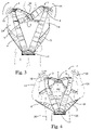
- FIG. 3 is a top perspective view showing the FIG. 1 embodiment being put on by a user.
- FIG. 4 is a top perspective view showing the FIG. 1 embodiment illustrating a user placing the lifting harness over his head, which completes the mounting process.
- FIG. 5 is a front plan view of one embodiment of the tension buckle.
- FIG. 6 is a side plan view of the FIG. 5 embodiment of the tension buckle.
- FIG. 7 is bottom plan view of the FIG. 5 embodiment of the tension buckle.
- FIG. 8 is a side perspective view of two users lifting a dresser with the FIG. 1 embodiment.
- FIG. 9 is a top perspective view of an alternate embodiment central ring for enabling three or more users to combine their straps under a heavy load.
- FIG. 10 is a front plan view of another embodiment of the lifting harness.
- FIG. 11 is a front plan view of another embodiment of the lifting harness.
- a figure eight continuous strap forms a right shoulder loop 3 and a left shoulder loop 4 .
- Loops 3 , 4 may form an “X” pattern across user's 2 back 6 .
- the “X” pattern may be held together on back 6 of user 2 with closure material 7 .
- Closure material 7 may be constructed from, but is not limited to, hook and latch material, thread, zippers etc. Closure material 7 may prevent travel of the rear portions of loops 3 , 4 . All loads may be shared evenly by loops 3 , 4 .
- Loops 3 , 4 may be connected to a tension buckle 13 , which is about seven-inches wide.
- FIG. 3 user 2 is beginning to place lift harness 1 over user's 2 shoulders 18 shown in FIG. 4 .
- User 2 puts arms 14 through the lower portion of loops 3 , 4 and places hands 16 on the upper portion of loops 3 , 4 .
- the outer surface of closure material 7 is about level with user's 2 head 10 .
- user 2 then raises arms 14 and lift harness 1 so that user 2 can place user's 2 head 10 through loops 3 , 4 .
- user 2 places his head through loops 3 , 4 and lowers arms 14 , the upper portions of loops 3 , 4 rest on user's 2 shoulders 18 and the lower portions of loops 3 , 4 rest at user's 2 sides 20 .
- tension buckle 13 is about seven-inches wide, 1 1 is about 7-inches. Loops 3 , 4 may run through slots 50 , 51 of tension buckle 13 .
- a central roller 54 is knurled and slides up and down in slot 55 on side panels 52 , 53 via end pieces 56 , thereby allowing for locking of lift strap 22 under a load.
- the single, wide lift strap helps provide stability when placed directly under large objects as shown in FIG. 8 .
- Nominal dimensions for tension buckle 13 are: 1 2 is about 5-inches, 1 3 is about 1-inch, 1 4 is about 1.875-inches, 1 5 is about 2.625-inches, 1 6 is about 3.00-inches, 1 7 is about 0.2 1 8 is about 0.125-inches, 1 9 is about 0.375-inches, 1 10 is about 0.4375-inches, 1 11 i about 0.1875-inches.
- Lift strap 22 is about five-inches wide and may be made of a webbed construction. However, any suitable material known in the art may be used. End 24 threads through tension buckle 13 in a known manner to allow user 2 to cinch up lift strap 22 under dresser 30 after lift strap 22 is placed under dresser 30 . Each user's 2 arms 14 are free to steady the load, dresser 30 . Dresser 30 may be delivered across a pebble surface, cracked pavement and/or a wet surface without damage and over surfaces where wheels on a dolly or hand truck would not function.
- FIG. 9 four users (not shown) each have a lift strap 22 .
- a central ring 82 joins all four lift straps 22 .
- the central ring 82 is placed under a heavy load 84 , shown in dotted lines, to share the lifting among the four users.
- a single continuous strap forms a right shoulder loop 3 and a left shoulder loop 4 .
- Central horizontal members 102 form an “H” pattern across the front and back of user 2 (not shown). The “H” pattern may be held together on the front and back of user 2 (not shown) with closure material 7 .
- Closure material 7 may be constructed from, but is not limited to, hook and latch material, thread, zippers etc.
- Central horizontal members 102 may help prevent shoulder loops 3 , 4 from falling off the shoulders. While two central horizontal members are shown, only one central horizontal member 102 is necessary to prevent shoulder loops 3 , 4 from falling off the shoulders. All loads may be shared evenly by loops 3 , 4 . Loops 3 , 4 may be connected to a tension buckle 13 , which is about seven-inches wide.
- Optional waist band loop segments 3 a , 4 a may be attached to lift harness 100 for additional support.
- a single continuous strap forms right shoulder loop 113 .
- a second, single continuous strap forms left shoulder loop 114 .
- Loops 113 , 114 may be connected to each other by central horizontal members 102 .
- Central horizontal members 102 form an “H” pattern across the front and back of user 2 (not shown). The “H” pattern may held together on the front and back of user 2 (not shown) with closure material 7 .
- Closure material 7 may be constructed from, but is not limited to, hook and latch material, thread, zippers etc.
- Central horizontal members 102 may help prevent shoulder loops 113 , 114 from falling off the shoulders.
- Loops 113 , 114 may be connected to a tension buckle 13 , which is about seven-inches wide.
Abstract
Description
Claims (8)
Priority Applications (3)
| Application Number | Priority Date | Filing Date | Title |
|---|---|---|---|
| US10/845,940 US7331493B2 (en) | 2004-05-14 | 2004-05-14 | Simplified two-man lifting harness |
| PCT/US2005/017132 WO2005112689A1 (en) | 2004-05-14 | 2005-05-16 | Simplified two-man lifting harness |
| CA002589757A CA2589757A1 (en) | 2004-05-14 | 2005-05-16 | Simplified two-man lifting harness |
Applications Claiming Priority (1)
| Application Number | Priority Date | Filing Date | Title |
|---|---|---|---|
| US10/845,940 US7331493B2 (en) | 2004-05-14 | 2004-05-14 | Simplified two-man lifting harness |
Publications (2)
| Publication Number | Publication Date |
|---|---|
| US20050263551A1 US20050263551A1 (en) | 2005-12-01 |
| US7331493B2 true US7331493B2 (en) | 2008-02-19 |
Family
ID=34971732
Family Applications (1)
| Application Number | Title | Priority Date | Filing Date |
|---|---|---|---|
| US10/845,940 Active - Reinstated 2024-11-14 US7331493B2 (en) | 2004-05-14 | 2004-05-14 | Simplified two-man lifting harness |
Country Status (3)
| Country | Link |
|---|---|
| US (1) | US7331493B2 (en) |
| CA (1) | CA2589757A1 (en) |
| WO (1) | WO2005112689A1 (en) |
Cited By (16)
| Publication number | Priority date | Publication date | Assignee | Title |
|---|---|---|---|---|
| US20080083795A1 (en) * | 2006-10-10 | 2008-04-10 | Lopreiato, Mark A. And Sophia Lopreiato, Trustees Of The Lopreiato Family Living Trust | Enhanced forearm furniture leverage straps |
| US20090294500A1 (en) * | 2008-05-30 | 2009-12-03 | Rooster Products International, Inc. | Load suspension system |
| US20100181793A1 (en) * | 2006-10-10 | 2010-07-22 | Lopreiato, Mark.A. and Sophia Lopreiato, Trustees of the Lopreiato Family Living Trust U/T/A | Enhanced forearm furniture leverage straps |
| US20100243372A1 (en) * | 2009-03-26 | 2010-09-30 | Wilkinson Justin M | Fireman's compact safety drag harness |
| US20130125342A1 (en) * | 2011-11-22 | 2013-05-23 | Donald Lupa | Furniture skid plate |
| US8807403B2 (en) | 2011-05-07 | 2014-08-19 | Corey David Nielsen | Strap lifter for use between two persons |
| US20160287935A1 (en) * | 2015-03-31 | 2016-10-06 | Steven Douglas Sykes | Isometric/Isotonic Neck Exercise Device |
| US9596922B2 (en) | 2011-05-07 | 2017-03-21 | Corey David Nielsen | Strap lifter for use between two persons |
| EP3202280A1 (en) | 2016-02-02 | 2017-08-09 | Corey David Nielsen | Strap lifter for use between two persons with multiple lifting options |
| US20180093124A1 (en) * | 2016-09-30 | 2018-04-05 | Tony E. Roybal | Neck Hanging Weight System |
| US10349622B2 (en) * | 2016-01-04 | 2019-07-16 | Timothy B. Price | Animal transport apparatus |
| US10391920B2 (en) * | 2015-06-03 | 2019-08-27 | Timothy P. Squires | Device for attaching an object and a method of attaching an object using the device |
| USD891723S1 (en) | 2019-02-14 | 2020-07-28 | Corey David Nielsen | Lifting strap |
| USD907857S1 (en) | 2019-02-14 | 2021-01-12 | Nielsen Products, Llc | Lifting harness |
| US11013653B1 (en) * | 2021-01-25 | 2021-05-25 | Christopher Atkins | Caregiver lifting harness and use thereof |
| US11357312B2 (en) * | 2018-11-30 | 2022-06-14 | Honda Motor Co., Ltd. | Working machine support belt |
Families Citing this family (10)
| Publication number | Priority date | Publication date | Assignee | Title |
|---|---|---|---|---|
| US7311343B2 (en) | 2006-10-05 | 2007-12-25 | Callebresi Jerry F | Temporary handles for moving awkwardly sized objects |
| US8066161B2 (en) | 2007-07-13 | 2011-11-29 | Green Robert D | Hands-free lifting and carrying apparatus |
| US20090140019A1 (en) * | 2007-12-03 | 2009-06-04 | Shawn Martinich | Appliance-supporting strap system and method |
| US9044080B2 (en) * | 2010-06-21 | 2015-06-02 | Yohannes Ashenafi | Shoulder strap carrying device |
| US8321972B1 (en) | 2012-05-14 | 2012-12-04 | Diane Vetter | Easily adjustable lifting belt |
| SE1250825A1 (en) * | 2012-07-12 | 2013-12-17 | Coxa Carry Ab | Carrying system with carrying straps |
| ES2582496B1 (en) * | 2015-03-12 | 2017-07-11 | Pedro Luis PÉREZ ARAGÓN | Harness for transporting travel bags |
| EP3141146A1 (en) * | 2015-09-11 | 2017-03-15 | Bernd Engels | Carrying device |
| FR3052448B1 (en) * | 2016-06-14 | 2018-05-18 | Nicolas Czerwinski | HANDLING HARNESS WITH FOLDING TRAY |
| US11284699B2 (en) * | 2020-02-10 | 2022-03-29 | Rolland Fontaine | Body-worn aid for decedent removal and other load-moving applications |
Citations (36)
| Publication number | Priority date | Publication date | Assignee | Title |
|---|---|---|---|---|
| US1490066A (en) | 1921-12-21 | 1924-04-08 | Legatee Genoa Lillian Carr | Sling and buckle |
| US1500510A (en) | 1923-04-30 | 1924-07-08 | Mcelvar Carl | Carrier for miners' battery boxes |
| US1535208A (en) * | 1922-01-07 | 1925-04-28 | Undertakers Supply Company | Body lifter |
| US1879480A (en) | 1929-08-02 | 1932-09-27 | John A Pures | Body harness |
| US1995439A (en) * | 1933-01-17 | 1935-03-26 | Grace Lankford | Buckle |
| FR790246A (en) | 1935-05-18 | 1935-11-16 | Adjustment buckle applicable in particular to the straps and straps of aviators' equipment | |
| US2431780A (en) | 1946-04-23 | 1947-12-02 | William A Theal | Load-carrying means |
| US2477432A (en) * | 1948-01-26 | 1949-07-26 | Heston J Walsh | Harness for transporting power saws |
| US2528078A (en) * | 1945-10-01 | 1950-10-31 | Quilter John Raymond Cuthbert | Frictional locking buckle |
| US2651441A (en) | 1950-04-11 | 1953-09-08 | Atlantic Builder S Supply Corp | Carrier for plate-form building material |
| US2743497A (en) * | 1953-03-25 | 1956-05-01 | Davis Aircraft Products Inc | Slide buckle |
| US2855133A (en) * | 1957-04-16 | 1958-10-07 | Kenneth R Freshour | Harness and trip-hook |
| US3120403A (en) | 1961-06-21 | 1964-02-04 | Aeroquip Corp | Cargo sling |
| US3258788A (en) * | 1963-02-06 | 1966-07-05 | Anciaux Albert Theobald Henri | Harness construction |
| USD267598S (en) | 1980-10-02 | 1983-01-18 | Lyer Daniel M | Adjustable article carrying harness |
| US4406348A (en) | 1981-12-09 | 1983-09-27 | Switlik Ii Stanley | Clip for safety harnesses |
| US4887752A (en) | 1982-07-19 | 1989-12-19 | Nauta Adriaen E R | Self-locking transport strap |
| GB2224193A (en) | 1988-10-26 | 1990-05-02 | Anthony Frederick Bridge | A lifting harness |
| US5009349A (en) | 1988-07-08 | 1991-04-23 | Eide Geir O | Lifting and carrying device |
| JPH03205204A (en) | 1989-10-31 | 1991-09-06 | Mitsubishi Electric Corp | Transporting device |
| US5269449A (en) | 1991-12-12 | 1993-12-14 | Sattler Warren A | Supplemental carry strap |
| US5289896A (en) * | 1992-09-10 | 1994-03-01 | Giglio Salvatore J | Harness for a motorcyclist and the like |
| US5307967A (en) | 1991-12-10 | 1994-05-03 | Seals Michael L | Article carrier |
| EP0596839A2 (en) | 1992-10-19 | 1994-05-11 | Giancarlo Caputi | Multi-purpose carrying system |
| US5466040A (en) | 1994-01-27 | 1995-11-14 | Fainsztein; Henry | High rise evacuation chair |
| US5503448A (en) | 1994-07-29 | 1996-04-02 | Dewey; Don L. | Strap apparatus for hauling large objects |
| US5588940A (en) | 1995-06-12 | 1996-12-31 | Price; Eric M. | Weight supporting body harness |
| US5890227A (en) * | 1995-11-28 | 1999-04-06 | Brown; Jason C. | EMT technician vest |
| US5927781A (en) | 1997-07-09 | 1999-07-27 | Lyons, Jr.; Thomas F. | Strap apparatus for carrying relatively large objects |
| US6039376A (en) | 1997-11-25 | 2000-03-21 | Lopreiato; Mark Anthony | Forearm furniture leverage straps |
| FR2809936A3 (en) | 2000-06-08 | 2001-12-14 | Baltic | Self locking buckle for cargo strap has pair of flanges with openings for sliding cross bar which selectively clamps strap between itself and fixed bar |
| US6446849B1 (en) | 2000-06-21 | 2002-09-10 | Jason E. Schleifer | Carrying device |
| US20020148866A1 (en) | 2001-04-17 | 2002-10-17 | Dent Thomas E. | Lifting Harness |
| US6508389B1 (en) | 1999-11-15 | 2003-01-21 | Robert K. Ripoyla | Harness system for lifting objects |
| US6641008B2 (en) * | 2002-01-18 | 2003-11-04 | Sure-Strap, Inc. | Shoulder strap harness lifting device |
| US6790201B2 (en) * | 2000-04-06 | 2004-09-14 | Helen B. Meyer | Strap assemblies and methods of use thereof |
-
2004
- 2004-05-14 US US10/845,940 patent/US7331493B2/en active Active - Reinstated
-
2005
- 2005-05-16 WO PCT/US2005/017132 patent/WO2005112689A1/en active Application Filing
- 2005-05-16 CA CA002589757A patent/CA2589757A1/en not_active Abandoned
Patent Citations (37)
| Publication number | Priority date | Publication date | Assignee | Title |
|---|---|---|---|---|
| US1490066A (en) | 1921-12-21 | 1924-04-08 | Legatee Genoa Lillian Carr | Sling and buckle |
| US1535208A (en) * | 1922-01-07 | 1925-04-28 | Undertakers Supply Company | Body lifter |
| US1500510A (en) | 1923-04-30 | 1924-07-08 | Mcelvar Carl | Carrier for miners' battery boxes |
| US1879480A (en) | 1929-08-02 | 1932-09-27 | John A Pures | Body harness |
| US1995439A (en) * | 1933-01-17 | 1935-03-26 | Grace Lankford | Buckle |
| FR790246A (en) | 1935-05-18 | 1935-11-16 | Adjustment buckle applicable in particular to the straps and straps of aviators' equipment | |
| US2528078A (en) * | 1945-10-01 | 1950-10-31 | Quilter John Raymond Cuthbert | Frictional locking buckle |
| US2431780A (en) | 1946-04-23 | 1947-12-02 | William A Theal | Load-carrying means |
| US2477432A (en) * | 1948-01-26 | 1949-07-26 | Heston J Walsh | Harness for transporting power saws |
| US2651441A (en) | 1950-04-11 | 1953-09-08 | Atlantic Builder S Supply Corp | Carrier for plate-form building material |
| US2743497A (en) * | 1953-03-25 | 1956-05-01 | Davis Aircraft Products Inc | Slide buckle |
| US2855133A (en) * | 1957-04-16 | 1958-10-07 | Kenneth R Freshour | Harness and trip-hook |
| US3120403A (en) | 1961-06-21 | 1964-02-04 | Aeroquip Corp | Cargo sling |
| US3258788A (en) * | 1963-02-06 | 1966-07-05 | Anciaux Albert Theobald Henri | Harness construction |
| USD267598S (en) | 1980-10-02 | 1983-01-18 | Lyer Daniel M | Adjustable article carrying harness |
| US4406348A (en) | 1981-12-09 | 1983-09-27 | Switlik Ii Stanley | Clip for safety harnesses |
| US4887752A (en) | 1982-07-19 | 1989-12-19 | Nauta Adriaen E R | Self-locking transport strap |
| US5009349A (en) | 1988-07-08 | 1991-04-23 | Eide Geir O | Lifting and carrying device |
| GB2224193A (en) | 1988-10-26 | 1990-05-02 | Anthony Frederick Bridge | A lifting harness |
| JPH03205204A (en) | 1989-10-31 | 1991-09-06 | Mitsubishi Electric Corp | Transporting device |
| US5307967A (en) | 1991-12-10 | 1994-05-03 | Seals Michael L | Article carrier |
| US5269449A (en) | 1991-12-12 | 1993-12-14 | Sattler Warren A | Supplemental carry strap |
| US5289896A (en) * | 1992-09-10 | 1994-03-01 | Giglio Salvatore J | Harness for a motorcyclist and the like |
| EP0596839A2 (en) | 1992-10-19 | 1994-05-11 | Giancarlo Caputi | Multi-purpose carrying system |
| US5466040A (en) | 1994-01-27 | 1995-11-14 | Fainsztein; Henry | High rise evacuation chair |
| US5503448A (en) | 1994-07-29 | 1996-04-02 | Dewey; Don L. | Strap apparatus for hauling large objects |
| US5588940A (en) | 1995-06-12 | 1996-12-31 | Price; Eric M. | Weight supporting body harness |
| US5890227A (en) * | 1995-11-28 | 1999-04-06 | Brown; Jason C. | EMT technician vest |
| US5927781A (en) | 1997-07-09 | 1999-07-27 | Lyons, Jr.; Thomas F. | Strap apparatus for carrying relatively large objects |
| US6039376A (en) | 1997-11-25 | 2000-03-21 | Lopreiato; Mark Anthony | Forearm furniture leverage straps |
| US6508389B1 (en) | 1999-11-15 | 2003-01-21 | Robert K. Ripoyla | Harness system for lifting objects |
| US6790201B2 (en) * | 2000-04-06 | 2004-09-14 | Helen B. Meyer | Strap assemblies and methods of use thereof |
| FR2809936A3 (en) | 2000-06-08 | 2001-12-14 | Baltic | Self locking buckle for cargo strap has pair of flanges with openings for sliding cross bar which selectively clamps strap between itself and fixed bar |
| US6446849B1 (en) | 2000-06-21 | 2002-09-10 | Jason E. Schleifer | Carrying device |
| US20020148866A1 (en) | 2001-04-17 | 2002-10-17 | Dent Thomas E. | Lifting Harness |
| US6729511B2 (en) | 2001-04-17 | 2004-05-04 | Dent, Iii Thomas E. | Lifting harness |
| US6641008B2 (en) * | 2002-01-18 | 2003-11-04 | Sure-Strap, Inc. | Shoulder strap harness lifting device |
Cited By (22)
| Publication number | Priority date | Publication date | Assignee | Title |
|---|---|---|---|---|
| US7731069B2 (en) * | 2006-10-10 | 2010-06-08 | Mark A. Lopreiato | Enhanced forearm furniture leverage straps |
| US20100181793A1 (en) * | 2006-10-10 | 2010-07-22 | Lopreiato, Mark.A. and Sophia Lopreiato, Trustees of the Lopreiato Family Living Trust U/T/A | Enhanced forearm furniture leverage straps |
| US20080083795A1 (en) * | 2006-10-10 | 2008-04-10 | Lopreiato, Mark A. And Sophia Lopreiato, Trustees Of The Lopreiato Family Living Trust | Enhanced forearm furniture leverage straps |
| US20090294500A1 (en) * | 2008-05-30 | 2009-12-03 | Rooster Products International, Inc. | Load suspension system |
| US20100243372A1 (en) * | 2009-03-26 | 2010-09-30 | Wilkinson Justin M | Fireman's compact safety drag harness |
| US9596922B2 (en) | 2011-05-07 | 2017-03-21 | Corey David Nielsen | Strap lifter for use between two persons |
| US8807403B2 (en) | 2011-05-07 | 2014-08-19 | Corey David Nielsen | Strap lifter for use between two persons |
| US9101202B2 (en) | 2011-05-07 | 2015-08-11 | Corey David Nielsen | Strap lifter for use between two persons |
| US20130125342A1 (en) * | 2011-11-22 | 2013-05-23 | Donald Lupa | Furniture skid plate |
| US9185977B2 (en) * | 2011-11-22 | 2015-11-17 | Sd Machinery, Llc | Furniture skid plate |
| US20160287935A1 (en) * | 2015-03-31 | 2016-10-06 | Steven Douglas Sykes | Isometric/Isotonic Neck Exercise Device |
| US9901775B2 (en) * | 2015-03-31 | 2018-02-27 | Steven Douglas Sykes | Isometric/isotonic neck exercise device |
| US10589659B2 (en) | 2015-06-03 | 2020-03-17 | Timothy P. Squires | Device for attaching an object and method of attaching an object using the device |
| US10391920B2 (en) * | 2015-06-03 | 2019-08-27 | Timothy P. Squires | Device for attaching an object and a method of attaching an object using the device |
| US10349622B2 (en) * | 2016-01-04 | 2019-07-16 | Timothy B. Price | Animal transport apparatus |
| US9930955B2 (en) | 2016-02-02 | 2018-04-03 | Corey David Nielsen | Strap lifter for use between two persons with multiple lifting options |
| EP3202280A1 (en) | 2016-02-02 | 2017-08-09 | Corey David Nielsen | Strap lifter for use between two persons with multiple lifting options |
| US20180093124A1 (en) * | 2016-09-30 | 2018-04-05 | Tony E. Roybal | Neck Hanging Weight System |
| US11357312B2 (en) * | 2018-11-30 | 2022-06-14 | Honda Motor Co., Ltd. | Working machine support belt |
| USD891723S1 (en) | 2019-02-14 | 2020-07-28 | Corey David Nielsen | Lifting strap |
| USD907857S1 (en) | 2019-02-14 | 2021-01-12 | Nielsen Products, Llc | Lifting harness |
| US11013653B1 (en) * | 2021-01-25 | 2021-05-25 | Christopher Atkins | Caregiver lifting harness and use thereof |
Also Published As
| Publication number | Publication date |
|---|---|
| US20050263551A1 (en) | 2005-12-01 |
| WO2005112689A1 (en) | 2005-12-01 |
| CA2589757A1 (en) | 2005-12-01 |
Similar Documents
| Publication | Publication Date | Title |
|---|---|---|
| US7331493B2 (en) | Simplified two-man lifting harness | |
| US6729511B2 (en) | Lifting harness | |
| US6508389B1 (en) | Harness system for lifting objects | |
| US5713439A (en) | Dual point auxiliary luggage attachment system | |
| US5503448A (en) | Strap apparatus for hauling large objects | |
| US5267680A (en) | Carrying sling for infant carrier or car seat | |
| US5863056A (en) | Mattress moving system | |
| US5305897A (en) | Wall mounted skateboard storage rack | |
| US6039376A (en) | Forearm furniture leverage straps | |
| US6328131B1 (en) | Roll-up tree seat | |
| US7703645B2 (en) | Backpack adapter | |
| US10342319B1 (en) | Wearable load carrier | |
| US20040145202A1 (en) | Box carrying strap assembly | |
| US20070131726A1 (en) | Lifting harness and method of using the same | |
| US9596922B2 (en) | Strap lifter for use between two persons | |
| US20060033365A1 (en) | Carrying strap | |
| US5466040A (en) | High rise evacuation chair | |
| US5890769A (en) | Child restraining harness | |
| US3581961A (en) | Adjustable pack frame assembly | |
| US5267428A (en) | Cargo carrier for pack animals | |
| US5649744A (en) | Operator seat harness | |
| US20100140970A1 (en) | Support means for assisting in hauling an item | |
| US20100025445A1 (en) | Three piece lifting device | |
| US6736437B2 (en) | Mattress caddy | |
| CA2630994C (en) | Method and apparatus for providing lanyard securement to a transport trailer |
Legal Events
| Date | Code | Title | Description |
|---|---|---|---|
| AS | Assignment |
Owner name: TDT MOVING SYSTEMS, INC., COLORADO Free format text: ASSIGNMENT OF ASSIGNORS INTEREST;ASSIGNOR:DENT III, THOMAS E.;REEL/FRAME:016601/0009 Effective date: 20050524 |
|
| STCF | Information on status: patent grant |
Free format text: PATENTED CASE |
|
| CC | Certificate of correction | ||
| REMI | Maintenance fee reminder mailed | ||
| FPAY | Fee payment |
Year of fee payment: 4 |
|
| SULP | Surcharge for late payment | ||
| AS | Assignment |
Owner name: DEN, INC., COLORADO Free format text: ASSIGNMENT OF ASSIGNORS INTEREST;ASSIGNOR:TDT MOVING SYSTEMS, INC.;REEL/FRAME:034652/0414 Effective date: 20140929 |
|
| FPAY | Fee payment |
Year of fee payment: 8 |
|
| FEPP | Fee payment procedure |
Free format text: MAINTENANCE FEE REMINDER MAILED (ORIGINAL EVENT CODE: REM.); ENTITY STATUS OF PATENT OWNER: SMALL ENTITY |
|
| AS | Assignment |
Owner name: NIELSEN PRODUCTS, LLC, COLORADO Free format text: ASSIGNMENT OF ASSIGNORS INTEREST;ASSIGNOR:DEN, INC.;REEL/FRAME:050774/0554 Effective date: 20191018 |
|
| LAPS | Lapse for failure to pay maintenance fees |
Free format text: PATENT EXPIRED FOR FAILURE TO PAY MAINTENANCE FEES (ORIGINAL EVENT CODE: EXP.); ENTITY STATUS OF PATENT OWNER: SMALL ENTITY |
|
| PRDP | Patent reinstated due to the acceptance of a late maintenance fee |
Effective date: 20200403 |
|
| FEPP | Fee payment procedure |
Free format text: PETITION RELATED TO MAINTENANCE FEES FILED (ORIGINAL EVENT CODE: PMFP); ENTITY STATUS OF PATENT OWNER: SMALL ENTITY Free format text: SURCHARGE, PETITION TO ACCEPT PYMT AFTER EXP, UNINTENTIONAL. (ORIGINAL EVENT CODE: M2558); ENTITY STATUS OF PATENT OWNER: SMALL ENTITY Free format text: PETITION RELATED TO MAINTENANCE FEES GRANTED (ORIGINAL EVENT CODE: PMFG); ENTITY STATUS OF PATENT OWNER: SMALL ENTITY |
|
| MAFP | Maintenance fee payment |
Free format text: PAYMENT OF MAINTENANCE FEE, 12TH YR, SMALL ENTITY (ORIGINAL EVENT CODE: M2553); ENTITY STATUS OF PATENT OWNER: SMALL ENTITY Year of fee payment: 12 |
|
| STCF | Information on status: patent grant |
Free format text: PATENTED CASE |
|
| FP | Expired due to failure to pay maintenance fee |
Effective date: 20200219 |