US7331555B2 - Recessed electrical equipment fixture - Google Patents
Recessed electrical equipment fixture Download PDFInfo
- Publication number
- US7331555B2 US7331555B2 US10/989,906 US98990604A US7331555B2 US 7331555 B2 US7331555 B2 US 7331555B2 US 98990604 A US98990604 A US 98990604A US 7331555 B2 US7331555 B2 US 7331555B2
- Authority
- US
- United States
- Prior art keywords
- clip
- pot
- fixture
- wall
- fastener
- Prior art date
- Legal status (The legal status is an assumption and is not a legal conclusion. Google has not performed a legal analysis and makes no representation as to the accuracy of the status listed.)
- Expired - Fee Related, expires
Links
Images


Classifications
-
- F—MECHANICAL ENGINEERING; LIGHTING; HEATING; WEAPONS; BLASTING
- F21—LIGHTING
- F21V—FUNCTIONAL FEATURES OR DETAILS OF LIGHTING DEVICES OR SYSTEMS THEREOF; STRUCTURAL COMBINATIONS OF LIGHTING DEVICES WITH OTHER ARTICLES, NOT OTHERWISE PROVIDED FOR
- F21V21/00—Supporting, suspending, or attaching arrangements for lighting devices; Hand grips
- F21V21/02—Wall, ceiling, or floor bases; Fixing pendants or arms to the bases
- F21V21/04—Recessed bases
-
- H—ELECTRICITY
- H02—GENERATION; CONVERSION OR DISTRIBUTION OF ELECTRIC POWER
- H02G—INSTALLATION OF ELECTRIC CABLES OR LINES, OR OF COMBINED OPTICAL AND ELECTRIC CABLES OR LINES
- H02G3/00—Installations of electric cables or lines or protective tubing therefor in or on buildings, equivalent structures or vehicles
- H02G3/02—Details
- H02G3/08—Distribution boxes; Connection or junction boxes
- H02G3/12—Distribution boxes; Connection or junction boxes for flush mounting
- H02G3/123—Distribution boxes; Connection or junction boxes for flush mounting in thin walls
-
- H—ELECTRICITY
- H02—GENERATION; CONVERSION OR DISTRIBUTION OF ELECTRIC POWER
- H02G—INSTALLATION OF ELECTRIC CABLES OR LINES, OR OF COMBINED OPTICAL AND ELECTRIC CABLES OR LINES
- H02G3/00—Installations of electric cables or lines or protective tubing therefor in or on buildings, equivalent structures or vehicles
- H02G3/02—Details
- H02G3/08—Distribution boxes; Connection or junction boxes
- H02G3/18—Distribution boxes; Connection or junction boxes providing line outlets
- H02G3/20—Ceiling roses or other lighting sets
-
- Y—GENERAL TAGGING OF NEW TECHNOLOGICAL DEVELOPMENTS; GENERAL TAGGING OF CROSS-SECTIONAL TECHNOLOGIES SPANNING OVER SEVERAL SECTIONS OF THE IPC; TECHNICAL SUBJECTS COVERED BY FORMER USPC CROSS-REFERENCE ART COLLECTIONS [XRACs] AND DIGESTS
- Y10—TECHNICAL SUBJECTS COVERED BY FORMER USPC
- Y10S—TECHNICAL SUBJECTS COVERED BY FORMER USPC CROSS-REFERENCE ART COLLECTIONS [XRACs] AND DIGESTS
- Y10S248/00—Supports
- Y10S248/906—Electrical outlet box support
Definitions
- the present invention generally relates to recessed electrical equipment, such as, amongst others, light fixtures. More specifically, the present invention is concerned with a recessed electrical equipment fixture of the type having retaining clips for securing the fixture to a ceiling or to a wall surface.
- Recessed fixtures usually comprise a pot having a peripheral wall and a peripheral outer flange extending from the open end of the pot and which is so configured as to bear against the front surface of a ceiling.
- Clips are usually provided to secure the pot to a ceiling or wall surface. These clips generally extend from openings in the peripheral wall and are adjustably mounted to the pot through a fastener. More specifically, each clip is provided with a portion configured and sized to bear on the rear surface of the ceiling.
- Lecluze's fixture is not designed so as to be easily unclipped, for example after an unsuccessful mounting attempt or should it be necessary to remove it for any reason.
- the projection of the screw outwardly from the can towards in the ceiling or the like increases the minimum cavity height required for installation.
- Benghozi is fixedly secured to the pot and that it requires only two steps to install, it is not so designed as to be easily unclipped, for example after an unsuccessful mounting attempt or should it be necessary to remove it for any reason.
- the clip of Benghozi fixture is provided outside the pot when it is in a retracted position and may therefore be easily damaged during transport or installation.
- the clip since the clip has to be flexible to operate, it is not sufficiently stiff for some applications, where, for example, heavy charges are supported.
- An object of the present invention is therefore to provide an improved recessed electrical equipment fixture.
- a clip for mounting a pot into an opening in a wall structure defining front and rear wall surfaces, the pot being provided with a peripheral wall, an end wall at one longitudinal end of the peripheral wall, and a peripheral flange at the other end thereof for abutment with the front wall surface of the wall structure, the peripheral wall including a generally transversal slot and a generally longitudinal slot extending between the end wall and the peripheral flange and defining a longitudinal axis intersecting the transversal slot, the clip comprising: a body having a first longitudinal end defining a fastener-receiving portion for receiving a fastener to be secured to the end wall of the pot, a second longitudinal end defining a surface-abutting portion and a clip-mounting portion protruding from the body between the first and second longitudinal ends for slidably mounting the clip to the peripheral wall of the pot via the generally longitudinal slot so as to be reciprocately movable between a first position
- a recessed fixture for mounting into an opening in a wall structure defining front and rear wall surfaces
- the fixture comprising: a pot adapted to be received in the opening of the wall structure and having a peripheral wall, an end wall at one longitudinal end of the peripheral wall, and a peripheral flange at the other end thereof for abutment with the front wall surface of the wall structure; the pot defining a fixture chamber; a clip having a surface-abutting portion for abutting the rear surface of the wall; the clip being movably mounted to the peripheral wall of the pot so as to reciprocate between a retracted position where the clip is located inside the fixture chamber and a clipping position where the surface-abutting portion is located outside the fixture chamber and abuts the rear surface of the wall structure when the pot is received in the opening of the wall structure and the peripheral flange contacts the front surface of the wall structure; and a clip actuator coupled to both the clip and the pot for reciprocatively moving the clip between the retracted
- a recessed fixture for mounting into an opening in a wall structure defining front and rear wall surfaces
- the fixture comprising: a pot adapted to be received in the opening of the wall structure and having a peripheral wall, an end wall at one longitudinal end of the peripheral wall, and a peripheral flange at the other end thereof for abutment with the front wall surface of the wall structure; the pot defining a fixture chamber; a clip having a surface-abutting portion for abutting the rear surface of the wall; the clip being movably mounted to the peripheral wall of the pot so as to reciprocate between a retracted position where the surface-abutting portion is located inside the fixture chamber and a clipping position where the surface-abutting portion is located outside the fixture chamber and abuts the rear surface of the wall structure when the pot is received in the opening of the wall structure and the peripheral flange contacts the front surface of the wall structure; and a clip actuator to reciprocatively move the clip between the retracted position and the
- a recessed fixture for mounting into an opening in a wall structure defining front and rear wall surfaces
- the fixture comprising: a pot adapted to be received in the opening of the wall structure and having a peripheral wall, an end wall at one longitudinal end of the peripheral wall, and a peripheral flange at the other end thereof for abutment with the front wall surface of the wall structure; the pot defining a fixture chamber; a clip having a fastener-receiving portion, a surface-abutting portion and an intermediate portion provided between the fastener-receiving portion and the surface-abutting portion; the intermediate portion being mounted to the peripheral wall inside the fixture chamber so as to allow the clip to reciprocate between a retracted position and a clipping position; and a fastener to be mounted between the pot and the clip to reciprocatively move the clip between the retracted position and the clipping position.
- a recessed fixture for mounting into an opening in a wall structure defining front and rear wall surfaces
- the fixture comprising: a pot adapted to be received in the opening of the wall structure and having a peripheral wall, an end wall at one longitudinal end of the peripheral wall, and a peripheral flange at the other end thereof for abutment with the front wall surface of the wall structure; the pot defining a fixture chamber; a clip having a surface-abutting portion for abutting the rear surface of the wall; the clip being movably mounted to the peripheral wall of the pot so as to reciprocate between a retracted position and a clipping position; the surface-abutting portion being located outside the fixture chamber and is so configured as to be deflectable inside the fixture chamber to allow insertion of the recessed fixture into the wall opening; and a clip actuator for reciprocatively moving the clip between the retracted position and the clipping position.
- FIG. 1 is a cross-section of a recessed fixture according to a first illustrative embodiment of the present invention, illustrating the clip fully retracted;
- FIG. 2 is a cross-section of the pot part of the recessed fixture of FIG. 1 ;
- FIG. 3 is a perspective view of a clip part of the recessed fixture of FIG. 1 ;
- FIG. 4 is a cross-section of the recessed fixture of FIG. 1 , illustrating the clip partially extended;
- FIG. 5 is a cross-section of the recessed fixture of FIG. 1 , illustrating the clip fully extended;
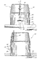
- FIG. 6 is a front elevation of a recessed fixture according to a second illustrative embodiment of the present invention, illustrating the clip retracted;
- FIG. 7 is a cross-section taken along line 7 - 7 on FIG. 6 ;
- FIG. 8 is a perspective view of the pot part of the recessed fixture of FIG. 6 ;
- FIG. 9 is a perspective view of the clip part of the recessed fixture of FIG. 6 ;
- FIG. 10 is an elevation of the recessed fixture of FIG. 1 , illustrating the clip partially extended;
- FIG. 11 is a cross-section taken along line 11 - 11 of FIG. 10 ;
- FIG. 12 is an elevation of the recessed fixture of FIG. 6 , illustrating the clip partially extended.
- FIG. 13 is a cross-section taken along line 13 - 13 of FIG. 12 .
- a recessed fixture 10 according to a first illustrative embodiment of the present invention will now be described with reference to FIGS. 1 to 5 .
- the fixture 10 is for mounting into an opening 12 in a wall structure 14 defining front and rear wall surfaces 16 and 18 .
- the fixture 10 comprises a pot 20 so configured and sized as to be inserted in the opening 12 of the wall structure 14 , two clips 22 (only one shown) for securing the pot 20 to the wall structure 14 within the opening 12 , and two fasteners 24 (only one shown) for securing the clips 22 to the pot 20 and for acting thereon.
- the pot 20 has a generally cylindrical shape defined by a peripheral wall 26 , and includes an end wall 28 at one longitudinal end of the peripheral wall 26 .
- the peripheral wall 26 is tapered near the end wall 28 so as to ease the insertion of the pot 20 into the opening 12 .
- the pot 20 thereby defines an open fixture chamber 21 .
- the end wall 28 is provided with an opening 30 for receiving electrical components allowing for example a light bulb (not shown) to be mounted and connected therein.
- the peripheral wall 26 may also be provided with such openings (not shown).
- the pot 20 further comprises a peripheral flange 32 at the longitudinal end of the peripheral wall opposite the end wall 28 .
- the flange 32 prevents the complete insertion of the pot 20 in the opening 12 since it is larger than the opening 12 and therefore abuts the front wall surface 16 .
- the flange 32 further allows the pot 20 to be secured to the wall structure 14 in cooperation with the clip 22 as will be described hereinbelow.
- the width of the flange 32 may of course vary.
- the pot 20 may have other configuration without departing from the spirit and nature of the present invention.
- the peripheral wall 26 may define a rectangular cross-section.
- the peripheral wall 26 of the pot 20 includes a pair of diametrically opposed cross-shaped slots 34 (only one shown), each including a generally longitudinally aligned slot 36 , extending between the vicinity of the end wall 28 and the vicinity of the peripheral flange 32 , and a transversal slot 38 perpendicularly intersecting the longitudinally aligned slot 36 .
- the longitudinal slot 36 defines a clip-receiving means. The configuration of the longitudinal slot 36 , including its length and width may vary, depending on the configuration of the clip 22 , as will also be explained hereinbelow in more detail.
- FIG. 3 the clip 22 will described in more detail.
- the clip 22 is in the form of a bended generally flat elongated body including a fastener-receiving portion 40 , a surface-abutting portion 42 and an intermediate portion in the form of a clip-mounting portion 44 for slidably mounting the clip 22 to the peripheral surface 26 of the pot 20 via the slot 36 .
- the fastener-receiving portion 40 includes a threaded aperture 46 configured to threadingly receive the fastener 24 .
- the surface-abutting portion 42 is generally flat and defines an obtuse angle with respect to the intermediate portion 44 . It includes a narrower section 43 and two shoulders 45 .
- the intermediate portion 44 includes a narrow section 48 adjacent to the fastener-receiving portion 40 , a clip mounting portion in the form of a generally T-shaped section 50 adjacent to the narrow portion 48 , a wide section 52 provided with a folded tab 54 and located adjacent to the T-shaped section 50 and a connecting section 56 located between the wide section 52 and the surface-abutting portion 42 .
- the fastener 24 includes a first end 58 that is devoid of threads and is inserted in an aperture 60 of the end wall 28 .
- the fastener 24 is therefore free to rotate in the aperture 60 without longitudinal movements therein.
- the second end 62 of the fastener 24 may be conventionally engaged by a screwdriver (not shown) to impart a rotating movement thereof.
- the clip 22 when the clip 22 is mounted to the pot 20 via the fastener 24 , the narrow section 48 is always inside the pot 20 while the wider portion of the T-shaped section 50 is always outside the pot 20 .
- the clip 22 is therefore mounted to the pot 20 both by the fastener 24 and by the frictional connection of the T-shape section 50 and the external surface of the pot 20 on each side of the slot 36 .
- the surface-abutting portion 42 is fully enclosed in the fixture chamber 21 of the pot 20 and contacts the inner surface of the pot 20 . Accordingly, the three points of contact between the clip 22 and the pot 20 creates a biasing force that tries to push the surface-abutting end 42 outwardly. Also, this biasing force allows preventing movement of the clip 22 when it is completely comprised within the pot 20 , which can be advantageous during shipping for example.
- the fastener 24 When the fastener 24 is rotated in a clockwise direction, it forces the clip 22 towards its extended position (see arrow 64 ). As can be seen from FIG. 4 , the movement of the clip 22 aligns the surface-abutting portion 42 with the transversal slot 38 which is configured and sized as to allow its passage therethrough. Accordingly, the biasing force described hereinabove forces the portion 42 outwardly. As can also be seen from FIG. 4 , the folded tab 54 rides in the longitudinal slot 36 to help the clip 22 to maintain its longitudinal attitude.
- the fastener 24 is further rotated to bring the surface-abutting portion 42 in contact with the rear surface 18 of the wall 14 .
- the clockwise rotation of the fastener 24 forces the clip 22 in the direction of arrow 65 .
- This movement forces the surface-abutting portion 42 outwardly since its angled underside 66 eventually contacts the edge 68 of the aperture 38 until the narrow section 43 enters the longitudinal slot 34 and the shoulders 45 abut the outside surface of the pot 20 on either sides of the slot 36 .
- FIG. 5 illustrate the clip 22 in its fully extended position where the surface-abutting portion 42 abuts the rear surface 18 of the wall 14 to thereby sandwich the wall 14 between the flange 32 and the portion 42 .
- the movement of the clip 22 from its fully retracted position illustrated in FIG. 1 to its fully extended position illustrated in FIG. 5 can be achieved solely by the use of the fastener 24 .
- the fastener 24 should be rotated in a counter-clockwise direction, the clip 22 would move back to its fully retracted position where the surface-abutting portion 42 is located inside the pot 20 , allowing the removal of the pot 20 from the aperture 12 .
- the top surface 70 of the surface-abutting portion 42 eventually contacts the edge 72 of the slot 38 to guide the surface-abutting portion 42 inside the fixture chamber 21 .
- cross-shapes slots 34 may vary. Accordingly, the number of clips 22 mounted to the pot 20 may also vary.
- the angle of the surface-abutting portion 42 with respect to a longitudinal direction of the pot 20 and the resilient nature of the clip 22 allows the pot 20 to be mounted to the aperture 10 even should the surface-abutting portion 42 be partially extended, for example as illustrated in FIG. 4 .
- the surface-abutting portion 42 would momentarily deflect inside the fixture chamber 21 and then resume its initial configuration. Therefore, mounting the pot 20 to the aperture 10 while the surface-abutting portion 42 is initially partially extended as illustrated in FIG. 4 also allows first securing the pot 20 within the aperture 12 before positioning the clip 22 in the clipping configuration illustrated in FIG. 5 .
- the clipping step then only requires the use of one hand since the pot 20 is prevented from falling from the opening 12 by the surface-abutting portion 42 which has returned to its partially extended initial configuration as soon as it is translated beyond the wall structure 14 .
- pulling the pot 20 causes the surface-abutting portion 42 to bear against the inner surface 18 of the wall structure 14 .
- the pot 20 may be released from the opening 12 in the wall structure 14 by unscrewing the fastener 24 .
- the clip 22 may be modified so as to be provided with a surface-abutting portion 42 presenting a different angle than what is illustrated with reference to FIGS. 1 and 3 - 5 while being partially-extended from the aperture 38 depending on the general resilience of the clip 22 while mounted to the pot 20 .
- FIGS. 6 to 13 of the appended drawings a recessed electrical equipment fixture 100 according to a second embodiment of the present invention will be described.
- the fixture 100 includes a pot 102 better seen in FIG. 8 , a clip 104 better seen in FIG. 9 and a fastener 106 for securing the clip 104 to the pot 102 .
- the pot 102 includes a peripheral wall 108 , an end wall 110 provided with an opening 112 and a peripheral flange 114 .
- the pot 102 also includes a clip receiving means in the form of a slot structure including a first inverted T-slot 116 , defined by a longitudinal slot 118 and a transversal slot 120 , and a cross-shaped slot 122 , defined by a longitudinal slot 124 and a non-regular transversal slot 126 . More specifically, the intersection between the longitudinal slot 124 and transversal slot 126 defines a tapered section 127 of the cross-shaped slot 122 .
- the clip 104 ( FIG. 9 ) is in the form of a bended generally flat elongated body including a fastener-receiving portion 128 , a surface-abutting portion 130 and an intermediate portion 132 for slidably mounting the clip 104 to the peripheral surface 108 of the pot 102 via the clip-receiving means.
- the fastener-receiving portion 128 includes a threaded aperture 134 configured to threadingly receive the fastener 106 .
- the surface-abutting portion 130 is generally flat and defines an obtuse angle with respect to the intermediate portion 132 .
- the surface-abutting portion 130 is connected to the intermediate portion 132 via a narrower section 136 defining two shoulders 138 .
- the intermediate portion 132 includes a clip mounting portion in the form of a generally T-shaped section 140 adjacent to the fastener-receiving portion 128 , a narrow section 142 adjacent generally T-shaped section 140 , a wide section 144 provided with a folded tab 146 and located between the narrow section 142 and the surface-abutting portion 130 .
- the transversal slot 120 is so sized to allow passage of the T-shaped section 140 therethrough.
- the transversal slot 126 is so sized that the surface-abutting portion 130 may pass therethrough.
- the folded flap 146 is configured and sized so as to fit in the longitudinal slot 124 to thereby help the clip 104 to maintain its longitudinal attitude.
- the tapered section 127 of the cross-shaped slot 122 allows contributing to the automatic insertion of the narrower section 136 into the portion of the longitudinal slot 124 located below the transversal slot 126 when the clip moves from a retracted position to a clipping position or its automatic withdrawal when it moves in the opposite direction.
- FIGS. 6 and 7 of the appended drawings illustrate the fixture 100 where the clip 104 is in a fully retracted position. As can be better seen from FIG. 7 , when the clip 104 is in this position, the surface-abutting portion 130 is fully enclosed in the pot 102 .
- FIGS. 10 and 11 illustrate the fixture 100 when the clip 104 is in an intermediary semi-extended position.
- the surface-abutting portion 130 is forced through the transversal slot 126 by the fastener 106 , which acts as a lever.
- the folded tab 146 is inserted in the longitudinal slot 124 .
- FIGS. 12 and 13 illustrate the fixture 100 when the clip 104 is in its clipping position. To reach this clipping position the fastener 106 is rotated clockwise.
- the present invention has been illustrated as including fasteners 24 or 106 which are pre-mounted to the clips 22 or 104 respectively and rotatably secured to the pot 20 or 102 respectively, the fasteners 24 or 106 can alternatively be initially secured only to the clips 22 or 104 before being installed to the pot 20 or 102 or be provided separately from both the clip and the pot.
- the clip 22 or 104 is moved between the retracted and clipping positions by rotating the fastener 24 or 106 , which is received in the aperture of the clip 22 or 104 , while a force is exerted on the fastener to ensure it contacts the end wall of the pot during rotation.
- an aperture is not provided in the end wall of the pot for receiving the fastener.
- a cavity may however be provided in the end wall of the pot for receiving the tip of the fastener to help prevent slippage of the fastener during the operation.
Abstract
Description
Claims (19)
Priority Applications (2)
| Application Number | Priority Date | Filing Date | Title |
|---|---|---|---|
| US10/989,906 US7331555B2 (en) | 2004-05-18 | 2004-11-17 | Recessed electrical equipment fixture |
| CA2507362A CA2507362C (en) | 2004-05-18 | 2005-05-16 | Recessed electrical equipment fixture |
Applications Claiming Priority (2)
| Application Number | Priority Date | Filing Date | Title |
|---|---|---|---|
| US57192404P | 2004-05-18 | 2004-05-18 | |
| US10/989,906 US7331555B2 (en) | 2004-05-18 | 2004-11-17 | Recessed electrical equipment fixture |
Publications (2)
| Publication Number | Publication Date |
|---|---|
| US20050258326A1 US20050258326A1 (en) | 2005-11-24 |
| US7331555B2 true US7331555B2 (en) | 2008-02-19 |
Family
ID=35374296
Family Applications (1)
| Application Number | Title | Priority Date | Filing Date |
|---|---|---|---|
| US10/989,906 Expired - Fee Related US7331555B2 (en) | 2004-05-18 | 2004-11-17 | Recessed electrical equipment fixture |
Country Status (2)
| Country | Link |
|---|---|
| US (1) | US7331555B2 (en) |
| CA (1) | CA2507362C (en) |
Cited By (7)
| Publication number | Priority date | Publication date | Assignee | Title |
|---|---|---|---|---|
| US20080023894A1 (en) * | 2006-07-31 | 2008-01-31 | Genlyte Thomas Group Llc | Captive Retaining Spring |
| US20080186718A1 (en) * | 2007-02-07 | 2008-08-07 | Antonio Magisano | Recessed Light Can Height Adjustment |
| WO2009109049A1 (en) * | 2008-03-06 | 2009-09-11 | Eclairage Contraste Inc. | Light fixture for mounting to a ceiling |
| US20110267826A1 (en) * | 2010-04-29 | 2011-11-03 | Cordelia Lighting, Inc. | Recessed can with spring loaded retainer clips |
| US9151456B2 (en) | 2012-07-25 | 2015-10-06 | Eurofase Inc. | Housing attaching devices and assemblies |
| USD756025S1 (en) * | 2014-04-01 | 2016-05-10 | Cooper Technologies Company | Recessed luminaire housing top |
| US11933475B1 (en) | 2021-10-04 | 2024-03-19 | Robert William Turner | Dual zone lighting system |
Families Citing this family (11)
| Publication number | Priority date | Publication date | Assignee | Title |
|---|---|---|---|---|
| US8465182B1 (en) * | 2010-08-27 | 2013-06-18 | Cooper Technologies Company | Apparatus and method for retro-fitting a recessed light fixture into an existing ceiling mounted assembly or penetration |
| US9541268B2 (en) * | 2014-02-03 | 2017-01-10 | Abl Ip Holding Llc | Ceiling clamp for recessed light mounting |
| CA2971209C (en) | 2014-12-16 | 2023-08-01 | Lucifer Lighting Company | Adjustable and/or recessed light fixtures and related components and methods |
| GB2541889A (en) * | 2015-09-01 | 2017-03-08 | michael jones Christopher | Apparatus for placement of an electrical socket outlet into a structure |
| EP3356727B1 (en) * | 2015-09-28 | 2019-07-10 | Fischer Lighting ApS | Lamp housing with a locking device |
| US10798797B1 (en) * | 2016-03-28 | 2020-10-06 | Douglas Lighting Controls | Ceiling mount sensor assembly |
| US10524328B1 (en) | 2018-03-30 | 2019-12-31 | Douglas Lighting Controls | Fixture mount sensor with remote energy usage reporting |
| CN109489010B (en) * | 2018-12-20 | 2024-01-26 | 江门市韦尔达照明科技有限公司 | Embedded part and panel embedded equipment |
| US11067233B2 (en) | 2019-06-14 | 2021-07-20 | CP IP Holdings Limited | Lighting arrangement with battery backup |
| GB2597516B (en) * | 2020-07-24 | 2022-07-27 | Trade Secrets International Ltd | Pattress box |
| GB2598357A (en) * | 2020-08-28 | 2022-03-02 | Vincent Boden Bernard | A fixture housing for installation in a support surface |
Citations (21)
| Publication number | Priority date | Publication date | Assignee | Title |
|---|---|---|---|---|
| US2063923A (en) * | 1935-03-27 | 1936-12-15 | Fred W Gries | Clamping device for switch boxes and other fixtures |
| US2965348A (en) * | 1958-08-26 | 1960-12-20 | Gotham Lighting Corp | Lighting fixture suspension and attachment arrangement |
| US3620401A (en) * | 1970-05-11 | 1971-11-16 | Markstone Mfg Co | Recessed lighting fixture including mounting clamp means |
| US3748460A (en) | 1971-08-10 | 1973-07-24 | E Price | Recessed suspended lighting fixture |
| US4250540A (en) * | 1979-08-23 | 1981-02-10 | Mcgraw-Edison Co. | Mounting arrangement for recessed light fixture housing |
| US4293895A (en) * | 1979-08-23 | 1981-10-06 | Mcgraw-Edison Company | Mounting arrangement for recessed light fixture housing |
| US4431151A (en) * | 1981-07-21 | 1984-02-14 | Robert L. Fournier | Fixture supporting clip |
| US4733339A (en) * | 1986-08-21 | 1988-03-22 | Cooper Industries | Mounting system for recessed light fixture |
| US5068772A (en) * | 1990-08-30 | 1991-11-26 | Troy Lighting, Inc. | Recessed lighting fixture |
| US5264994A (en) * | 1991-03-21 | 1993-11-23 | Choi Yoong J | Recessed illuminating apparatus |
| US5314148A (en) * | 1992-12-16 | 1994-05-24 | Csl Lighting, Inc. | Spring mount fixture housing |
| US5377088A (en) * | 1993-03-03 | 1994-12-27 | Lecluze; Michel | Light fixture for mounting to a ceiling, wall or the like |
| US5609414A (en) * | 1995-11-24 | 1997-03-11 | Canlyte Inc. | Recessed lighting fixture |
| US5826970A (en) | 1996-12-17 | 1998-10-27 | Effetre U.S.A. | Light transmissive trim plate for recessed lighting fixture |
| US5931432A (en) * | 1998-04-16 | 1999-08-03 | Pelco | Recessed-mounted housing |
| US5941625A (en) * | 1997-12-11 | 1999-08-24 | Bazz Inc. | Spring clip for a recessed light fixture assembly |
| US6364512B1 (en) | 1999-06-15 | 2002-04-02 | Sidler Gmbh & Co. | Light housing |
| US6505960B2 (en) | 2001-03-19 | 2003-01-14 | Cooper Industries, Inc. | Recessed lighting fixture locking assembly |
| US6554458B1 (en) * | 2001-08-10 | 2003-04-29 | Bazz, Inc. | Recessed light fixture |
| US20030223240A1 (en) | 2002-05-31 | 2003-12-04 | #9060-0495 Quebec, Inc. | Recessed light fixture |
| US6827471B1 (en) * | 2003-05-15 | 2004-12-07 | Bazz Inc. | Recessed light fixture |
Family Cites Families (1)
| Publication number | Priority date | Publication date | Assignee | Title |
|---|---|---|---|---|
| JP3615125B2 (en) * | 2000-03-30 | 2005-01-26 | 株式会社マキタ | Oil unit and power tool |
-
2004
- 2004-11-17 US US10/989,906 patent/US7331555B2/en not_active Expired - Fee Related
-
2005
- 2005-05-16 CA CA2507362A patent/CA2507362C/en not_active Expired - Fee Related
Patent Citations (21)
| Publication number | Priority date | Publication date | Assignee | Title |
|---|---|---|---|---|
| US2063923A (en) * | 1935-03-27 | 1936-12-15 | Fred W Gries | Clamping device for switch boxes and other fixtures |
| US2965348A (en) * | 1958-08-26 | 1960-12-20 | Gotham Lighting Corp | Lighting fixture suspension and attachment arrangement |
| US3620401A (en) * | 1970-05-11 | 1971-11-16 | Markstone Mfg Co | Recessed lighting fixture including mounting clamp means |
| US3748460A (en) | 1971-08-10 | 1973-07-24 | E Price | Recessed suspended lighting fixture |
| US4250540A (en) * | 1979-08-23 | 1981-02-10 | Mcgraw-Edison Co. | Mounting arrangement for recessed light fixture housing |
| US4293895A (en) * | 1979-08-23 | 1981-10-06 | Mcgraw-Edison Company | Mounting arrangement for recessed light fixture housing |
| US4431151A (en) * | 1981-07-21 | 1984-02-14 | Robert L. Fournier | Fixture supporting clip |
| US4733339A (en) * | 1986-08-21 | 1988-03-22 | Cooper Industries | Mounting system for recessed light fixture |
| US5068772A (en) * | 1990-08-30 | 1991-11-26 | Troy Lighting, Inc. | Recessed lighting fixture |
| US5264994A (en) * | 1991-03-21 | 1993-11-23 | Choi Yoong J | Recessed illuminating apparatus |
| US5314148A (en) * | 1992-12-16 | 1994-05-24 | Csl Lighting, Inc. | Spring mount fixture housing |
| US5377088A (en) * | 1993-03-03 | 1994-12-27 | Lecluze; Michel | Light fixture for mounting to a ceiling, wall or the like |
| US5609414A (en) * | 1995-11-24 | 1997-03-11 | Canlyte Inc. | Recessed lighting fixture |
| US5826970A (en) | 1996-12-17 | 1998-10-27 | Effetre U.S.A. | Light transmissive trim plate for recessed lighting fixture |
| US5941625A (en) * | 1997-12-11 | 1999-08-24 | Bazz Inc. | Spring clip for a recessed light fixture assembly |
| US5931432A (en) * | 1998-04-16 | 1999-08-03 | Pelco | Recessed-mounted housing |
| US6364512B1 (en) | 1999-06-15 | 2002-04-02 | Sidler Gmbh & Co. | Light housing |
| US6505960B2 (en) | 2001-03-19 | 2003-01-14 | Cooper Industries, Inc. | Recessed lighting fixture locking assembly |
| US6554458B1 (en) * | 2001-08-10 | 2003-04-29 | Bazz, Inc. | Recessed light fixture |
| US20030223240A1 (en) | 2002-05-31 | 2003-12-04 | #9060-0495 Quebec, Inc. | Recessed light fixture |
| US6827471B1 (en) * | 2003-05-15 | 2004-12-07 | Bazz Inc. | Recessed light fixture |
Cited By (14)
| Publication number | Priority date | Publication date | Assignee | Title |
|---|---|---|---|---|
| US7673842B2 (en) * | 2006-07-31 | 2010-03-09 | Koninklijke Philips Electronics, N.V | Captive retaining spring |
| US20080023894A1 (en) * | 2006-07-31 | 2008-01-31 | Genlyte Thomas Group Llc | Captive Retaining Spring |
| US20080186718A1 (en) * | 2007-02-07 | 2008-08-07 | Antonio Magisano | Recessed Light Can Height Adjustment |
| US7530717B2 (en) * | 2007-02-07 | 2009-05-12 | Genlyte Thomas Group Llc | Recessed light can height adjustment |
| EP2250435A4 (en) * | 2008-03-06 | 2011-04-06 | Eclairage Contraste Inc | Light fixture for mounting to a ceiling |
| EP2250435A1 (en) * | 2008-03-06 | 2010-11-17 | Eclairage Contraste Inc. | Light fixture for mounting to a ceiling |
| WO2009109049A1 (en) * | 2008-03-06 | 2009-09-11 | Eclairage Contraste Inc. | Light fixture for mounting to a ceiling |
| US20110110106A1 (en) * | 2008-03-06 | 2011-05-12 | Benoit Dupuy | Light fixture for mounting to a ceiling |
| US8545063B2 (en) | 2008-03-06 | 2013-10-01 | Eclairage Contraste M.L. Inc. | Light fixture for mounting to a ceiling |
| US20110267826A1 (en) * | 2010-04-29 | 2011-11-03 | Cordelia Lighting, Inc. | Recessed can with spring loaded retainer clips |
| US8308322B2 (en) * | 2010-04-29 | 2012-11-13 | Cordelia Lighting, Inc. | Recessed can with spring loaded retainer clips |
| US9151456B2 (en) | 2012-07-25 | 2015-10-06 | Eurofase Inc. | Housing attaching devices and assemblies |
| USD756025S1 (en) * | 2014-04-01 | 2016-05-10 | Cooper Technologies Company | Recessed luminaire housing top |
| US11933475B1 (en) | 2021-10-04 | 2024-03-19 | Robert William Turner | Dual zone lighting system |
Also Published As
| Publication number | Publication date |
|---|---|
| CA2507362A1 (en) | 2005-11-18 |
| CA2507362C (en) | 2010-04-13 |
| US20050258326A1 (en) | 2005-11-24 |
Similar Documents
| Publication | Publication Date | Title |
|---|---|---|
| CA2507362C (en) | Recessed electrical equipment fixture | |
| US7234832B2 (en) | Adjustable lighting fixture | |
| US7413323B2 (en) | Adjustable lighting fixture | |
| US4958792A (en) | Clip for supporting conduit and the like | |
| US20020176762A1 (en) | Removable and reusable fastener | |
| EP1942227A2 (en) | Enclosure-to-rail retaining system and method | |
| US2567884A (en) | Sheet metal fastener for securing members to supports | |
| US20110110106A1 (en) | Light fixture for mounting to a ceiling | |
| KR20160045585A (en) | Fastening element and assembly with such a fastening element and a receiving element | |
| US20140064874A1 (en) | Plug-in nut | |
| US4593441A (en) | Retainer clip | |
| US6074144A (en) | Fastener with retained movable pin | |
| CN111237298A (en) | Tolerance compensation device | |
| CN114198374A (en) | A connecting system for connecting at least two, in particular plate-like, elements; assembly comprising such a connection system | |
| US7614835B2 (en) | Simple fastening device | |
| CN113454347A (en) | Channel fastener with torque inducing elements | |
| JP2011247296A (en) | Fixing device | |
| US20070137403A1 (en) | Rod clip | |
| US11828321B2 (en) | Tolerance-compensating device comprising coupling means | |
| EP1281877A1 (en) | Device for the provisional retention of a screw assembly on a guide rail | |
| EP1607641B1 (en) | Fastening assembly | |
| JP2533139Y2 (en) | Recessed lighting fixture | |
| JP2735821B2 (en) | Lighting fixture mounting structure | |
| JP2011066986A (en) | Structure for screw body installation part, and wiring accessory mounting body | |
| JPH0223192Y2 (en) |
Legal Events
| Date | Code | Title | Description |
|---|---|---|---|
| AS | Assignment |
Owner name: LES LUMINAIRES EUREKA LIGHTING, CANADA Free format text: ASSIGNMENT OF ASSIGNORS INTEREST;ASSIGNOR:ST-PIERRE, GUY;REEL/FRAME:016796/0594 Effective date: 20041208 |
|
| STCF | Information on status: patent grant |
Free format text: PATENTED CASE |
|
| FEPP | Fee payment procedure |
Free format text: PAYOR NUMBER ASSIGNED (ORIGINAL EVENT CODE: ASPN); ENTITY STATUS OF PATENT OWNER: SMALL ENTITY |
|
| FPAY | Fee payment |
Year of fee payment: 4 |
|
| FPAY | Fee payment |
Year of fee payment: 8 |
|
| AS | Assignment |
Owner name: EUREKA LIGHTING INC., CANADA Free format text: CORRECTIVE ASSIGNMENT TO CORRECT THE ASSIGNEE NAME PREVIOUSLY RECORDED AT REEL: 016796 FRAME: 0594. ASSIGNOR(S) HEREBY CONFIRMS THE ASSIGNMENT;ASSIGNOR:ST-PIERRE, GUY;REEL/FRAME:038858/0429 Effective date: 20160525 |
|
| AS | Assignment |
Owner name: THE LUMINAIRES GROUP U.S.A., LLC, NEW YORK Free format text: ASSIGNMENT OF ASSIGNORS INTEREST;ASSIGNOR:EUREKA LIGHTING INC.;REEL/FRAME:038989/0851 Effective date: 20160607 |
|
| AS | Assignment |
Owner name: THE GOVERNOR AND COMPANY OF THE BANK OF IRELAND, A Free format text: CORRECTIVE ASSIGNMENT TO CORRECT THE INCORRECT PATENT NO. D733155 PREVIOUSLY RECORDED AT REEL: 038989 FRAME: 0876. ASSIGNOR(S) HEREBY CONFIRMS THE SECURITY INTEREST;ASSIGNOR:THE LUMINAIRES GROUP U.S.A., LLC;REEL/FRAME:040322/0935 Effective date: 20160607 |
|
| AS | Assignment |
Owner name: THE LUMINAIRES GROUP U.S.A., LLC, NEW YORK Free format text: RELEASE BY SECURED PARTY;ASSIGNOR:THE GOVERNOR AND COMPANY OF THE BANK OF IRELAND, AS COLLATERAL AGENT;REEL/FRAME:050404/0854 Effective date: 20190917 |
|
| FEPP | Fee payment procedure |
Free format text: MAINTENANCE FEE REMINDER MAILED (ORIGINAL EVENT CODE: REM.); ENTITY STATUS OF PATENT OWNER: SMALL ENTITY |
|
| LAPS | Lapse for failure to pay maintenance fees |
Free format text: PATENT EXPIRED FOR FAILURE TO PAY MAINTENANCE FEES (ORIGINAL EVENT CODE: EXP.); ENTITY STATUS OF PATENT OWNER: SMALL ENTITY |
|
| STCH | Information on status: patent discontinuation |
Free format text: PATENT EXPIRED DUE TO NONPAYMENT OF MAINTENANCE FEES UNDER 37 CFR 1.362 |
|
| FP | Lapsed due to failure to pay maintenance fee |
Effective date: 20200219 |