US7333575B2 - Method and apparatus for receiving a CDMA signal - Google Patents
Method and apparatus for receiving a CDMA signal Download PDFInfo
- Publication number
- US7333575B2 US7333575B2 US10/729,422 US72942203A US7333575B2 US 7333575 B2 US7333575 B2 US 7333575B2 US 72942203 A US72942203 A US 72942203A US 7333575 B2 US7333575 B2 US 7333575B2
- Authority
- US
- United States
- Prior art keywords
- stage
- sttd
- receiver
- output
- signal
- Prior art date
- Legal status (The legal status is an assumption and is not a legal conclusion. Google has not performed a legal analysis and makes no representation as to the accuracy of the status listed.)
- Expired - Fee Related, expires
Links
Images


Classifications
-
- H—ELECTRICITY
- H04—ELECTRIC COMMUNICATION TECHNIQUE
- H04B—TRANSMISSION
- H04B7/00—Radio transmission systems, i.e. using radiation field
- H04B7/02—Diversity systems; Multi-antenna system, i.e. transmission or reception using multiple antennas
- H04B7/04—Diversity systems; Multi-antenna system, i.e. transmission or reception using multiple antennas using two or more spaced independent antennas
- H04B7/08—Diversity systems; Multi-antenna system, i.e. transmission or reception using multiple antennas using two or more spaced independent antennas at the receiving station
- H04B7/0891—Space-time diversity
-
- H—ELECTRICITY
- H04—ELECTRIC COMMUNICATION TECHNIQUE
- H04B—TRANSMISSION
- H04B1/00—Details of transmission systems, not covered by a single one of groups H04B3/00 - H04B13/00; Details of transmission systems not characterised by the medium used for transmission
- H04B1/69—Spread spectrum techniques
- H04B1/707—Spread spectrum techniques using direct sequence modulation
- H04B1/7097—Interference-related aspects
- H04B1/7103—Interference-related aspects the interference being multiple access interference
- H04B1/7107—Subtractive interference cancellation
- H04B1/71075—Parallel interference cancellation
-
- H—ELECTRICITY
- H04—ELECTRIC COMMUNICATION TECHNIQUE
- H04B—TRANSMISSION
- H04B7/00—Radio transmission systems, i.e. using radiation field
- H04B7/02—Diversity systems; Multi-antenna system, i.e. transmission or reception using multiple antennas
- H04B7/04—Diversity systems; Multi-antenna system, i.e. transmission or reception using multiple antennas using two or more spaced independent antennas
- H04B7/06—Diversity systems; Multi-antenna system, i.e. transmission or reception using multiple antennas using two or more spaced independent antennas at the transmitting station
- H04B7/0613—Diversity systems; Multi-antenna system, i.e. transmission or reception using multiple antennas using two or more spaced independent antennas at the transmitting station using simultaneous transmission
- H04B7/0667—Diversity systems; Multi-antenna system, i.e. transmission or reception using multiple antennas using two or more spaced independent antennas at the transmitting station using simultaneous transmission of delayed versions of same signal
- H04B7/0669—Diversity systems; Multi-antenna system, i.e. transmission or reception using multiple antennas using two or more spaced independent antennas at the transmitting station using simultaneous transmission of delayed versions of same signal using different channel coding between antennas
-
- H—ELECTRICITY
- H04—ELECTRIC COMMUNICATION TECHNIQUE
- H04L—TRANSMISSION OF DIGITAL INFORMATION, e.g. TELEGRAPHIC COMMUNICATION
- H04L1/00—Arrangements for detecting or preventing errors in the information received
- H04L1/02—Arrangements for detecting or preventing errors in the information received by diversity reception
- H04L1/06—Arrangements for detecting or preventing errors in the information received by diversity reception using space diversity
- H04L1/0618—Space-time coding
-
- H—ELECTRICITY
- H04—ELECTRIC COMMUNICATION TECHNIQUE
- H04L—TRANSMISSION OF DIGITAL INFORMATION, e.g. TELEGRAPHIC COMMUNICATION
- H04L25/00—Baseband systems
- H04L25/02—Details ; arrangements for supplying electrical power along data transmission lines
- H04L25/03—Shaping networks in transmitter or receiver, e.g. adaptive shaping networks
- H04L25/03006—Arrangements for removing intersymbol interference
- H04L25/03012—Arrangements for removing intersymbol interference operating in the time domain
- H04L25/03019—Arrangements for removing intersymbol interference operating in the time domain adaptive, i.e. capable of adjustment during data reception
- H04L25/03038—Arrangements for removing intersymbol interference operating in the time domain adaptive, i.e. capable of adjustment during data reception with a non-recursive structure
-
- H—ELECTRICITY
- H04—ELECTRIC COMMUNICATION TECHNIQUE
- H04B—TRANSMISSION
- H04B1/00—Details of transmission systems, not covered by a single one of groups H04B3/00 - H04B13/00; Details of transmission systems not characterised by the medium used for transmission
- H04B1/69—Spread spectrum techniques
- H04B1/707—Spread spectrum techniques using direct sequence modulation
- H04B1/7097—Interference-related aspects
- H04B1/7103—Interference-related aspects the interference being multiple access interference
- H04B1/7105—Joint detection techniques, e.g. linear detectors
- H04B1/71055—Joint detection techniques, e.g. linear detectors using minimum mean squared error [MMSE] detector
-
- H—ELECTRICITY
- H04—ELECTRIC COMMUNICATION TECHNIQUE
- H04B—TRANSMISSION
- H04B1/00—Details of transmission systems, not covered by a single one of groups H04B3/00 - H04B13/00; Details of transmission systems not characterised by the medium used for transmission
- H04B1/69—Spread spectrum techniques
- H04B1/707—Spread spectrum techniques using direct sequence modulation
- H04B1/7097—Interference-related aspects
- H04B1/711—Interference-related aspects the interference being multi-path interference
- H04B1/7115—Constructive combining of multi-path signals, i.e. RAKE receivers
Definitions
- the present invention relates generally to radio telephony, and more specifically to a method and apparatus for receiving and processing a radio signal that is subject to transmission-channel distortion.
- Radio telephones commonly called cellular (or “cell”) phones
- cellular or “cell” phones
- radio telephones are now used by a majority of the population in this country and in many other regions around the world.
- Considerable leaps in technology have contributed significantly to this evolution. These advances have not only made radio telephone service available to many subscribers at a reasonable price, but they have also permitted great increases in the capacity of the communication networks providing the service.
- the cell phone is so called because it is designed to operate within a cellular network.
- a network has infrastructure that switches and routes calls to and from network subscribers who are using portable radio devices.
- the cellular network is divided into a great many smaller areas, or “cells”, each having an antenna of their own.
- a cellular wireless system has several advantages over a central antenna system. As the cells are much smaller than the large geographic area covered by a central antenna, transmitters do not need as much power. This is particularly important where the transmitter is housed in a small device such as a cell phone.
- low-power transmitters means that although the number of them operating in any one cell is still limited, the cells are small enough that a great many may operate in an area the size of a major city.
- the mobile stations do not transmit with enough power to interfere with others operating in other cells, or at least those cells that are not adjoining. In some networks, this enables frequency reuse, that is, the same communication frequencies can be used in non-adjacent cells at the same time without interference. This permits the addition of a larger number of network subscribers.
- codes used for privacy or signal processing may be reused in a similar manner.
- radio telephones such as “cellular (or cell) phone” and “mobile phone” are often used interchangeably, they will be treated as equivalent herein. Both, however, are a sub-group of a larger family of devices that also includes, for example, certain computers and personal digital assistants (PDAs) that are also capable of wireless radio communication in a radio network. This family of devices will for convenience be referred to as “mobile stations” (regardless of whether a particular device is actually moved about in normal operation).
- PDAs personal digital assistants
- FDMA frequency-division multiple access
- TDMA Time-division multiple access
- CDMA Code-division multiple access
- CDMA mobile stations that can operate in a given area is therefore limited by the number of encoding sequences available, rather than the number of frequency bands.
- the operation of a CDMA network is normally performed in accordance with a protocol referred to as IS-95 (interim standard-95) or, increasingly, according to its third generation (3G) successors, such as those sometimes referred to as 1xEV-DO and 1xEV-DV, the latter of which provides for the transport of both data and voice information.
- IS-95 interim standard-95
- 3G third generation
- FIG. 1 is a simplified block diagram illustrating selected components of a wireless transmission system 100 .
- Wireless transmission system 100 includes a transmit side 105 and a receive side 155 . This illustration implies that the two sides are located in different terminals that are attempting to communicate with each other, although typically a communication terminal will include both transmit and receive functions.
- the information to be transmitted which may be voice or data information, is first provided to an encoder 110 to be encoded into digital form.
- the encoded information is then mapped to symbols in a modulator 120 and provided to transmitter 130 , where it is modulated onto a carrier wave and amplified for transmission via radio channel 150 through antenna 140 .
- the receiver 170 receives the transmitted radio frequency (RF) signal x through antenna 160 .
- the received signal y is processed by the receiver 170 provides and the result ⁇ circumflex over (d) ⁇ to a demodulator 180 , which recovers the encoded sequence û (as well as it is able) taking into account the characteristics h of channel 150 .
- This encoded sequence û is provided to a decoder 190 for replication of the originally transmitted information. As should be apparent, the goal of any such communication system is the faithful reproduction of this information.
- Time diversity involves introducing time-delayed redundancy into the transmitted data and, where the fading is time variant, allows the receiver to more accurately recover the transmitted information.
- Spatial diversity may also be used. In spatial diversity more than one transmission antenna is used, the antennas being spaced apart at a distance selected to provide a desired level of correlation between the data transmitted by each of the antennas.
- a combination of these two types of transmit diversity may be referred to as space-time transmit diversity (STTD).
- the present invention is a receiver, a system, and a method for utilizing STTD transmitted signals and is of particular advantage when applied to a third-generation CDMA network, for example one operating according to the 1xEV-DV protocol.
- the present invention is directed to the reception of data in radio signals transmitted in a network that employs space-time transmit diversity (STTD).
- STTD space-time transmit diversity
- the present invention is a receiver for receiving an STTD transmitted signal including a RAKE-STTD receiver as a first stage of the receiver for receiving and processing the STTD signal and at least a second stage receiver.
- the second stage receiver performs STTD parallel interference cancellation (STTD-PIC) using the output of the first stage and the received signal as its input, and produces a refined estimate of the transmitted data.
- STTD-PIC STTD parallel interference cancellation
- the second state preferably includes an STTD-linear minimum mean square error (LMMSE) receiver that is used to process the refined estimate before it is output.
- LMMSE STTD-linear minimum mean square error
- the receiver may also include a third stage including an STTD-PIC and an STTD-LMMSE for further processing the output of the second stage to produce a further refined estimate. Stages subsequent to the RAKE-STTD may also process the received signal itself to produce an improved channel estimate.
- the present invention is a system for communicating data via radio signals including an STTD transmitter and an STTD-signal receiver having at least one antenna, the receiver including a first stage RAKE-STTD for receiving the radio signals and a STTD-PIC second stage for receiving the output of the RAKE-STTD and further processing it to produced a refined estimate of the transmitted data.
- the second stage may also include an STTD-LMMSE.
- the receiver of the system may also include a plurality of antennas to increase the diversity gain.
- the present invention is a method of receiving a data-bearing radio signal that has been transmitted using STTD including the steps of receiving indications of the received radio signal in a first stage RAKE-STTD receiver and processing the signal in the first stage to produce an estimate of the transmitted data as output, receiving as input in a second stage of the receiver the output of the first stage, and the original received signal as well, and processing the input received in the second stage to produce a refined estimate of the data as output.
- FIG. 1 is a simplified functional block diagram illustrating selected components of a wireless transmission system.
- FIG. 2 is a functional block diagram illustrating selected components that may be used on the transmit side of a system employing STTD according to an embodiment of the present invention.
- FIG. 3 is a simplified schematic drawing illustrating the antenna configuration of a telecommunication system utilizing transmit diversity for operating according to an embodiment of the present invention.
- FIG. 4 is a simplified schematic drawing illustrating the 2-1 diversity transmit antenna diversity configuration of FIG. 3 .
- FIG. 5 is a functional block diagram illustrating selected components of a receiver 500 according to an embodiment of the present invention
- FIG. 6 is a simplified schematic drawing illustrating the antenna configuration of a telecommunication system utilizing both transmit and receive diversity according to an embodiment of the present invention.
- FIG. 7 is a flow chart illustrating a method of receiving and processing a radio signal according to an embodiment of the present invention.
- FIGS. 1 through 7 discussed herein, and the various embodiments used to describe the present invention are by way of illustration only, and should not be construed to limit the scope of the invention. Those skilled in the art will understand the principles of the present invention may be implemented in any similar radio-communication device, in addition to those specifically discussed herein.
- FIG. 2 is a functional block diagram illustrating selected components that may be used on the transmit side 200 of a system employing STTD according to an embodiment of the present invention.
- the selected transmission components 200 are arranged with the intent of sending a signal to a compatible receiver (not shown in FIG. 2 ), such as one operable according to an embodiment of the present invention.
- the information (data) to be transmitted is provided to encoder 205 , and the encoded information is then provided to modulator 210 .
- the modulated bit stream b 0 , b 1 , b 2 , b 3 , . . . is provided to splitter 215 where it is split into two streams: b 0 , b 1 , b 2 , b 3 , . . . and ⁇ b 1 *, b 0 *, ⁇ b 3 *, b 2 *, . . . (where “*” denotes a complex conjugate).
- Each of these streams is then spread with respect to time using a spreading code W 32 , such as a Walsh-Hadamard code (length 32), by multiplier 220 and multiplier 230 , respectively. Pilot signals are added to the spread signal in adders 224 and 234 , respectively, then a pseudonoise (PN) code is applied to each stream in respective multipliers 228 and 238 to create two multi-coded spread sequences represented in FIG. 2 by the vectors s and s*.
- W 32 such as a Walsh-Hadamard code (length 32)
- FIG. 3 is a simplified schematic drawing illustrating the antenna configuration of a telecommunication system 300 utilizing transmit diversity for operating according to an embodiment of the present invention.
- Transmit antenna TX 1 and transmit antenna TX 2 are both transmitting different forms of the same information for reception by receive antenna RX 1 .
- the information being transmitted from antenna TX 1 is designated as signals s 0 , s 1 , and the information transmitted from antenna TX 2 as signals ⁇ s 1 * , s 0 *.
- Transmit antennas TX 1 and TX 2 are typically present in the same physical device, for example a wireless network base station, and may form a transmit station as described above in relation to FIG. 2 .
- Receiver RX 1 will typically be part of another wireless communication device such as a mobile station.
- the configuration of FIG. 3 is said to exhibit 2-1 diversity in reference to the number of transmit and receive antennas. Note, however, that for a given transmission there may be any number of intended receiving stations (each having its own antenna). In other words, 2-1 diversity may be used to send broadcast or multicast transmissions, in addition to those intended for a single recipient.
- Each combination of transmit antenna and receive antenna defines a channel, and therefore in the embodiment of FIG. 3 there are two, designated h 11 and h 21 .
- antenna TX 1 transmits signal s 0 at time t and s 1 at time t+T, where T is the symbol period
- antenna TX 2 transmits signal ⁇ s 1 * at time t and s 0 * at t+T
- FIG. 4 is a simplified schematic drawing illustrating the 2-1 diversity transmit antenna diversity configuration 300 of FIG. 3 , except that for simplicity the STTD transmitted signals s 0 , s 1 are generally represented as x 1 and the signals ⁇ s 1 *, s 0 * are represented as x 2 . Correspondingly, the received signal r 0 , r 1 are together represented as y and the additive noise v. Note, however, that although only two signals were illustrated in FIG. 3 , the vectors x and y could represent any number of signals.
- the received signal y may be represented as:
- y [ H 11 ⁇ H 21 ] ⁇ [ x 1 x 2 ] + v
- y [y n+F , y n+F ⁇ 1 , . . . y n ] T
- n the chip index
- F+1 the number of filter (chip equalizer) taps per transmit antenna.
- v [v n+F , v n+F ⁇ 1 , . . . v n ] T , and represents the additive noise sequence of autocorrelation matrix R vv .
- H 11 [ h 11 , 0 h 11 , 1 ⁇ H 11 , L 0 ⁇ 0 0 h 11 , 0 h 11 , 1 ⁇ h 11 , L ⁇ ⁇ ⁇ ⁇ ⁇ 0 0 ⁇ 0 h 11 , 0 h 11 , 1 ⁇ h 11 , L ]
- H 21 [ h 21 , 0 h 21 , 1 ⁇ H 21 , L 0 ⁇ 0 0 h 21 , 0 h 21 , 1 ⁇ h 21 , L ⁇ ⁇ ⁇ ⁇ ⁇ 0 ⁇ 0 h 21 , 0 h 21 , 1 ⁇ h 21 , L ] ⁇ ⁇ ⁇ ⁇ ⁇ 0 ⁇ h 21 , 0 h 21 , 1 ⁇ h 21 , L ] .
- H [H 11 H 21 ] and
- x [ x 1 x 2 ]
- FIG. 5 is a functional block diagram illustrating selected components of a receiver 500 according to an embodiment of the present invention.
- Receiver 500 includes an STTD-RAKE receiver as a first-stage 510 that processes incoming signal y as described above, and outputs estimated encoded bits û and/or symbols ⁇ circumflex over (d) ⁇ . Note that CDMA devices commonly employ RAKE receivers to combat multipath fading.
- the basic principle of the RAKE receiver involves selecting a limited number of individual paths of the transmitted signal. The time-delay between different paths arises because the signal is traveling from the transmitter to the receiver. Each selected path is provided to a different RAKE “finger”.
- each finger of the RAKE-STTD receiver uses a time-aligner to compensate for the path delay.
- the pilot PN quadrature spreading is then removed and the characteristics of the transmission channel are estimated using the pilot channels.
- a code such as a 32-length Walsh-Hadamard code (assuming the same having been employed in the transmitter) is used to despread the received signal, and then the STTD-transmitted signal is decoded as described above.
- the decoded results of all fingers are then combined and passed to the demodulator to yield the RAKE-STTD output represented in FIG. 5 as û, ⁇ circumflex over (d) ⁇ .
- Estimated data û, ⁇ circumflex over (d) ⁇ is provided to second stage 520 .
- the second stage 520 of receiver 500 is a first STTD-PIC, which then operates to refine the estimate as follows.
- K to represent the number of active spreading codes (except those used for the pilot channels)
- 11 and 21 represent the overall channel impulse response between each respective transmit antenna and the receive antenna (see, for example, FIG. 3 ).
- ⁇ circumflex over (x) ⁇ j [ ⁇ circumflex over (x) ⁇ 1,j T , ⁇ circumflex over (x) ⁇ 2,j T ] T is used to represent the reconstructed chip signal of a whole transmitted frame from both antennas, based on decisions of the previous stage, of all the active spreading codes of the system (including the pilot)—except the j th spreading code.
- the multiuser interference “seen” by the j th spreading code is ⁇ circumflex over (x) ⁇ j where is defined over the entire frame.
- the PIC of second stage 520 then subtracts this interference from the received chip vector y to produce (ideally) an interference-free signal for the j th spreading code.
- This signal which may be represented as y ⁇ ⁇ circumflex over (x) ⁇ j , is then passed through an STTD-LMMSE receiver 525 incorporated as part of second stage 520 to yield the symbol estimates for the j th code for the next stage.
- the STTD-LMMSE (linear minimum mean square error) receiver is an LMMSE chip equalizer filter followed by a bank of matched filters, which in turn is followed by a decision device.
- An LMMSE chip equalizer filter seeks to minimize the mean-squared error between its output and the transmitted chip sequence x n (n being the chip index).
- the STTD-LMMSE will try to detect the two transmitted streams (x 1 and x 2 ), and it is the solution to the minimization:
- W LMMSE arg m n E ⁇ w H y ⁇ x n ⁇ 2 ⁇ , where w is the (F+1) ⁇ 2 filter to be found and
- R vv is the noise process correlation matrix.
- R xx ⁇ x 2 I
- ⁇ tilde over (h) ⁇ F is an (F+1) ⁇ 2 matrix whose first and second columns are the F th columns of H 11 and H 21 (shown above ), respectively (counting starts from 0).
- w LMMSE ( HH H + 1 ⁇ x 2 ⁇ R vv ) - 1 ⁇ h ⁇ F .
- K is the number of active spreading codes (a user may have an assigned one, or multiple codes).
- the symbol estimates and the bit estimates of all users are denoted ⁇ circumflex over (d) ⁇ (2) , û (2) , respectively and are passed to the third stage 530 of receiver 500 .
- Third stage 530 is also an STTD-PIC incorporating an STTD-LMMSE 535 , and performs an operation similar to that described above with reference to the (first STTD-PIC of) second stage 520 , but using its input ⁇ circumflex over (d) ⁇ (2) , û (2) and y to produce a further refined data estimate û (3) , ⁇ circumflex over (d) ⁇ (3) .
- Bit or symbol estimates û (3) , ⁇ circumflex over (d) ⁇ (3) may be provided to a decoder (not shown), or may be subjected to further refinement in one or more additional STTD-PIC stages (also not shown).
- stages that include a PIC receiver can apply parallel interference cancellation to the pilot signal (or signals) for each transmit antenna, in an analogous fashion to that used for user symbols. This alternative may significantly improve channel estimation.
- FIG. 6 is a simplified schematic drawing illustrating the antenna configuration of a telecommunication system 600 utilizing both transmit and receive diversity according to an embodiment of the present invention. Similar to the embodiment of FIG. 4 , transmit antenna TX 1 and transmit antenna TX 2 are used to achieve transmit diversity for the transmitted signals. In the embodiment of FIG. 6 , however, each of the each of these transmissions is received by both receive antennas RX 1 and RX 2 , creating four separate transmission channels represented as h 11 , h 12 , h 21 , and h 22 . This configuration is said to exhibit 2-2 diversity.
- the two receivers RX 1 and RX 2 are normally located at the same device. There may be many such devices, of course, each receiving the same signal.
- the transmit diversity signal may be received and processed by devices having a single receive antenna as well as by devices having two (or more) receive antennas.
- the signals transmitted by antennas TX 1 and TX 2 are represented as x 1 and x 2 , respectively.
- the combined signal received at receiver RX 1 (including additive noise v 1 ) is represented as y 1
- the combined signal received at antenna RX 2 (plus noise v 2 ) as y 2 .
- the received signal y is represented as:
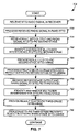
- FIG. 7 is a flow chart illustrating a method 700 of receiving a radio signal according to an embodiment of the present invention.
- the method begins when a radio signal is received at a receive filter (not shown in FIG. 5 ) of the receiver and then downsampled (steps not shown), resulting in a signal represented by a vector y.
- the downsampled signal y is then received at a first stage of the receiver (step 705 ), where it is processed using a RAKE-STTD receiver (step 710 ).
- the output û, ⁇ circumflex over (d) ⁇ (see FIG. 5 ) of the first stage is then received at the STTD-PIC second stage along with the downsampled signal y (step 715 ).
- multiuser interference is identified and subtracted from the signal (step 720 ), and the result provided to an STTD-LMMSE receiver incorporated within the STTD-PIC second stage (step 725 ) and processed to produce output û (2) , ⁇ circumflex over (d) ⁇ (2) (step 730 ).
- the STTD-LMMSE chip equalizer (filter) attempts to minimize the mean-squared error between the transmitted chip signal and the received LMMSE filtered signal. This is then received at the STTD-PIC third stage, which is provided with the downsampled signal y as well (step 745 ).
- multiuser interference is identified and subtracted from the signal (step 750 ), and the result provided to an STTD-LMMSE receiver incorporated within the STTD-PIC third stage (step 755 ).
- the third-stage STTD-LMMSE then processes the signal to produce output û (3) , ⁇ circumflex over (d) ⁇ (3) (step 760 ). This output is then provided to a decoder or, if present, a subsequent STTD-PIC stage or stages (step not shown).
Abstract
Description
r 0 =h 11 s 0 −h 21 s 1 *+n 0 and
r 1 =h 11 s 1 +h 21 s 0 *+n 1,
where n0 and n1 represent the additive noise at times t and t+T, respectively.
{tilde over (s)} 0 =h* 11 r 0 +h 21 r 1*=(|h 11|2 +|h 21|2)s 0 +n
{tilde over (s)} 1 =−h 21 r 0 *+h 11 *r 1=(|h 11|2 +h 21|2)s 1 +n′
where n and n′ are noise terms.
where y=[yn+F, yn+F−1, . . . yn]T, with n being the chip index, and F+1 the number of filter (chip equalizer) taps per transmit antenna. In this equation, the transmitted signal vector of size (F+1+L) for the first antenna is x1=[x1,n+F, x1,n+F−1, . . . , x1,n, . . . x1,n−L]T (and likewise for the second antenna). Further, v=[vn+F, vn+F−1, . . . vn]T, and represents the additive noise sequence of autocorrelation matrix Rvv.
Letting H=[H11 H21] and
can also be expressed y=Hx+v.
W LMMSE=arg m
where w is the (F+1)×2 filter to be found and
Minimization of this quantity will lead to Ryy WLMMSE=Ryx where Ryy≡E{yyH}=HRxxHH+Rvv. (Rvv is the noise process correlation matrix.) And finally
R yx ≡E{yx n *}=HE{xx n H}=σx 2 {tilde over (h)} F
where the autocorrelation of the transmitted signal is assumed:
Rxx=σx 2 I,
{tilde over (h)}F is an (F+1)×2 matrix whose first and second columns are the Fth columns of H11 and H21 (shown above ), respectively (counting starts from 0). Assuming that the transmitted signal is independent of the additive noise, this yields:
Naturally, the process described above is repeated with respect to each j=2, 3, . . . K, where K is the number of active spreading codes (a user may have an assigned one, or multiple codes). The symbol estimates and the bit estimates of all users are denoted {circumflex over (d)}(2), û(2), respectively and are passed to the
Claims (17)
Priority Applications (1)
| Application Number | Priority Date | Filing Date | Title |
|---|---|---|---|
| US10/729,422 US7333575B2 (en) | 2003-03-06 | 2003-12-05 | Method and apparatus for receiving a CDMA signal |
Applications Claiming Priority (3)
| Application Number | Priority Date | Filing Date | Title |
|---|---|---|---|
| US45287003P | 2003-03-06 | 2003-03-06 | |
| US10/395,831 US7313168B2 (en) | 2003-03-06 | 2003-03-24 | Method and apparatus for receiving a CDMA signal |
| US10/729,422 US7333575B2 (en) | 2003-03-06 | 2003-12-05 | Method and apparatus for receiving a CDMA signal |
Related Parent Applications (1)
| Application Number | Title | Priority Date | Filing Date |
|---|---|---|---|
| US10/395,831 Continuation-In-Part US7313168B2 (en) | 2003-03-06 | 2003-03-24 | Method and apparatus for receiving a CDMA signal |
Publications (2)
| Publication Number | Publication Date |
|---|---|
| US20040176051A1 US20040176051A1 (en) | 2004-09-09 |
| US7333575B2 true US7333575B2 (en) | 2008-02-19 |
Family
ID=46123523
Family Applications (1)
| Application Number | Title | Priority Date | Filing Date |
|---|---|---|---|
| US10/729,422 Expired - Fee Related US7333575B2 (en) | 2003-03-06 | 2003-12-05 | Method and apparatus for receiving a CDMA signal |
Country Status (1)
| Country | Link |
|---|---|
| US (1) | US7333575B2 (en) |
Cited By (1)
| Publication number | Priority date | Publication date | Assignee | Title |
|---|---|---|---|---|
| US8644412B2 (en) | 2003-12-19 | 2014-02-04 | Apple Inc. | Interference-weighted communication signal processing systems and methods |
Families Citing this family (5)
| Publication number | Priority date | Publication date | Assignee | Title |
|---|---|---|---|---|
| US8345733B2 (en) | 2005-09-13 | 2013-01-01 | At&T Intellectual Property I, Lp | Method and apparatus for equalizing signals |
| EP2061161B1 (en) * | 2007-11-14 | 2013-03-20 | Sony Corporation | Improved Alamouti encoding and decoding |
| US9042428B2 (en) * | 2012-05-04 | 2015-05-26 | Telefonaktiebolaget L M Ericsson (Publ) | Efficient frequency domain (FD) MMSE equalization weight updates in a multi-stage parallel interference cancellation receiver |
| KR102467707B1 (en) * | 2013-09-12 | 2022-11-17 | 돌비 인터네셔널 에이비 | Time-alignment of qmf based processing data |
| CN112994737B (en) * | 2021-02-09 | 2022-04-12 | 哈尔滨工业大学 | RAKE and MMSE cooperative despreading transmission method |
Citations (13)
| Publication number | Priority date | Publication date | Assignee | Title |
|---|---|---|---|---|
| US6278732B1 (en) | 1998-01-12 | 2001-08-21 | Hughes Electronics Corp. | Efficient MLSE equalization for quadrature multi-pulse (QMP) signaling |
| US6519477B1 (en) | 1997-03-25 | 2003-02-11 | Siemens Aktiengesellschaft | Method for channel estimation from received signals transmitted via a radio channel |
| US6526103B1 (en) | 1998-12-23 | 2003-02-25 | Nortel Networks Limited | Multi-stage receiver |
| US20030053526A1 (en) * | 1999-10-19 | 2003-03-20 | Interdigital Technology Corporation | Parallel interference cancellation receiver for multiuser detection of CDMA signals |
| US6570864B1 (en) * | 1998-11-16 | 2003-05-27 | Electronics And Telecommunications Research Institute | Integrated receiving apparatus of subtractive interference cancellation receiver and adaptive MMSE receiver |
| US6748024B2 (en) * | 2001-03-28 | 2004-06-08 | Nokia Corporation | Non-zero complex weighted space-time code for multiple antenna transmission |
| US6754253B2 (en) * | 2000-11-29 | 2004-06-22 | Ericsson Inc. | Receiver architecture for transmit diversity in CDMA system |
| US20040120299A1 (en) * | 2002-12-18 | 2004-06-24 | Anna Kidiyarova-Shevchenko | Method and apparatus for multi-user detection using RFSQ successive interference cancellation in CDMA wireless systems |
| US6775260B1 (en) * | 1999-02-25 | 2004-08-10 | Texas Instruments Incorporated | Space time transmit diversity for TDD/WCDMA systems |
| US20050002445A1 (en) * | 2003-01-30 | 2005-01-06 | Dunyak James P. | Sub-symbol parallel interference cancellation |
| US6975666B2 (en) * | 1999-12-23 | 2005-12-13 | Institut National De La Recherche Scientifique | Interference suppression in CDMA systems |
| US7023903B2 (en) * | 1999-12-15 | 2006-04-04 | Nokia Corporation | Method of receiving spread spectrum signal, and receiver |
| US7024166B2 (en) * | 2002-12-18 | 2006-04-04 | Qualcomm, Incorporated | Transmission diversity systems |
-
2003
- 2003-12-05 US US10/729,422 patent/US7333575B2/en not_active Expired - Fee Related
Patent Citations (13)
| Publication number | Priority date | Publication date | Assignee | Title |
|---|---|---|---|---|
| US6519477B1 (en) | 1997-03-25 | 2003-02-11 | Siemens Aktiengesellschaft | Method for channel estimation from received signals transmitted via a radio channel |
| US6278732B1 (en) | 1998-01-12 | 2001-08-21 | Hughes Electronics Corp. | Efficient MLSE equalization for quadrature multi-pulse (QMP) signaling |
| US6570864B1 (en) * | 1998-11-16 | 2003-05-27 | Electronics And Telecommunications Research Institute | Integrated receiving apparatus of subtractive interference cancellation receiver and adaptive MMSE receiver |
| US6526103B1 (en) | 1998-12-23 | 2003-02-25 | Nortel Networks Limited | Multi-stage receiver |
| US6775260B1 (en) * | 1999-02-25 | 2004-08-10 | Texas Instruments Incorporated | Space time transmit diversity for TDD/WCDMA systems |
| US20030053526A1 (en) * | 1999-10-19 | 2003-03-20 | Interdigital Technology Corporation | Parallel interference cancellation receiver for multiuser detection of CDMA signals |
| US7023903B2 (en) * | 1999-12-15 | 2006-04-04 | Nokia Corporation | Method of receiving spread spectrum signal, and receiver |
| US6975666B2 (en) * | 1999-12-23 | 2005-12-13 | Institut National De La Recherche Scientifique | Interference suppression in CDMA systems |
| US6754253B2 (en) * | 2000-11-29 | 2004-06-22 | Ericsson Inc. | Receiver architecture for transmit diversity in CDMA system |
| US6748024B2 (en) * | 2001-03-28 | 2004-06-08 | Nokia Corporation | Non-zero complex weighted space-time code for multiple antenna transmission |
| US20040120299A1 (en) * | 2002-12-18 | 2004-06-24 | Anna Kidiyarova-Shevchenko | Method and apparatus for multi-user detection using RFSQ successive interference cancellation in CDMA wireless systems |
| US7024166B2 (en) * | 2002-12-18 | 2006-04-04 | Qualcomm, Incorporated | Transmission diversity systems |
| US20050002445A1 (en) * | 2003-01-30 | 2005-01-06 | Dunyak James P. | Sub-symbol parallel interference cancellation |
Non-Patent Citations (6)
| Title |
|---|
| Cruickshank, Suppression of Multiple Access Interference In A DS-CDMA System Using Wiener Filtering And Parallel Cancellation, IEE Proc.-Commun., Aug. 8, 1996, 226-230, 143, 4. |
| Host-Madsen, et al., MMSE/PIC Multiuser Detection for DS/CDMA Systems With Inter- And Intra-Cell Interface, IEEE Transactions On Communications, Aug. 2, 1999, 291-299, 47, No. |
| Lin, et al., A Novel Multiuser Detection Scheme Combining Adaptive MMSE Receiver And Parallel Interference Canceller For Near-Far Resistance, IEEE, Aug. 20, 2002, 119-122. |
| Mahesh et al., "Multistage Detection in Asynchronous Code-Division Multiple-Access Communication," IEEE Transaction on Comm., 1990, pp. 509-519. * |
| Rezaaifar et al., "Multi-Stage Detection Scheme for CDMA System," IEEE 1997, pp. 474-477. * |
| Xue, Guoqiang et al., "Adaptive Multistage Parallel Interference Cancellation for CDMA," IEEE Journal on Selected Areas in Communications, vol. 17, No. 10, pp. 1251-1255, Oct. 1999. * |
Cited By (1)
| Publication number | Priority date | Publication date | Assignee | Title |
|---|---|---|---|---|
| US8644412B2 (en) | 2003-12-19 | 2014-02-04 | Apple Inc. | Interference-weighted communication signal processing systems and methods |
Also Published As
| Publication number | Publication date |
|---|---|
| US20040176051A1 (en) | 2004-09-09 |
Similar Documents
| Publication | Publication Date | Title |
|---|---|---|
| EP1172944B1 (en) | Wireless transmitter and receiver | |
| CA2157661C (en) | Method and system for demodulation of downlink cdma signals | |
| US6771689B2 (en) | Transmit diversity and reception equalization for radio links | |
| US7266355B2 (en) | Low complexity equalizer for radio receiver | |
| JP3091711B2 (en) | Method for demodulation and power control bit detection in spread spectrum communication systems | |
| US7623566B2 (en) | Method and apparatus for demodulating signals processed in a transmit diversity mode | |
| US7061854B2 (en) | Efficient OFDM communications with interference immunity | |
| EP1338101B1 (en) | Receiver architecture for transmit diversity in cdma system | |
| US20030013468A1 (en) | Radio communication system | |
| US6449266B1 (en) | Data transmission method, transmitter, and receiver | |
| US20030016637A1 (en) | Time interval based channel estimation with transmit diversity | |
| CN1339202A (en) | Apparatus and methods for interference cancellation in spread spectrum communication system | |
| KR100984053B1 (en) | Data processing method, equalizer, receiver, communication system, network element, and terminal using simplified channel matrix inversion | |
| JP4681180B2 (en) | CDMA signal component processing method | |
| US20050276311A1 (en) | Mt-cdma using spreading codes with interference-free windows | |
| US7313168B2 (en) | Method and apparatus for receiving a CDMA signal | |
| KR100733437B1 (en) | Modified block space time transmit diversity encoder | |
| US6078573A (en) | Circuitry and method for demodulating code division multiple access (CDMA) signals | |
| Anghel et al. | Relay assisted uplink communication over frequency-selective channels | |
| US7333575B2 (en) | Method and apparatus for receiving a CDMA signal | |
| EP1351426B1 (en) | Receiver and method for a space time encoded wireless communication system with multipath resolution | |
| US6925133B2 (en) | Apparatus and method for M-ary demodulation in a digital communication system | |
| CN101069346A (en) | Method and apparatus for receiving a CDMA signal | |
| Mucchi et al. | Space–Time MMSE Advanced Detector for Multisatellite Systems Under Nonideal Conditions | |
| Zhu | Blind Equalization and Multi-User Detection in Asynchronous Space-Time Coded CDMA System |
Legal Events
| Date | Code | Title | Description |
|---|---|---|---|
| AS | Assignment |
Owner name: NOKIA CORPORATION, FINLAND Free format text: ASSIGNMENT OF ASSIGNORS INTEREST;ASSIGNORS:PAPADIMITRIOU, PANAYIOTIS D.;VARSHNEY, PRABODH;REEL/FRAME:015125/0298 Effective date: 20031219 |
|
| STCF | Information on status: patent grant |
Free format text: PATENTED CASE |
|
| FPAY | Fee payment |
Year of fee payment: 4 |
|
| AS | Assignment |
Owner name: NOKIA TECHNOLOGIES OY, FINLAND Free format text: ASSIGNMENT OF ASSIGNORS INTEREST;ASSIGNOR:NOKIA CORPORATION;REEL/FRAME:035602/0129 Effective date: 20150116 |
|
| FPAY | Fee payment |
Year of fee payment: 8 |
|
| AS | Assignment |
Owner name: OMEGA CREDIT OPPORTUNITIES MASTER FUND, LP, NEW YORK Free format text: SECURITY INTEREST;ASSIGNOR:WSOU INVESTMENTS, LLC;REEL/FRAME:043966/0574 Effective date: 20170822 Owner name: OMEGA CREDIT OPPORTUNITIES MASTER FUND, LP, NEW YO Free format text: SECURITY INTEREST;ASSIGNOR:WSOU INVESTMENTS, LLC;REEL/FRAME:043966/0574 Effective date: 20170822 |
|
| AS | Assignment |
Owner name: WSOU INVESTMENTS, LLC, CALIFORNIA Free format text: ASSIGNMENT OF ASSIGNORS INTEREST;ASSIGNOR:NOKIA TECHNOLOGIES OY;REEL/FRAME:043953/0822 Effective date: 20170722 |
|
| AS | Assignment |
Owner name: BP FUNDING TRUST, SERIES SPL-VI, NEW YORK Free format text: SECURITY INTEREST;ASSIGNOR:WSOU INVESTMENTS, LLC;REEL/FRAME:049235/0068 Effective date: 20190516 |
|
| AS | Assignment |
Owner name: WSOU INVESTMENTS, LLC, CALIFORNIA Free format text: RELEASE BY SECURED PARTY;ASSIGNOR:OCO OPPORTUNITIES MASTER FUND, L.P. (F/K/A OMEGA CREDIT OPPORTUNITIES MASTER FUND LP;REEL/FRAME:049246/0405 Effective date: 20190516 |
|
| FEPP | Fee payment procedure |
Free format text: MAINTENANCE FEE REMINDER MAILED (ORIGINAL EVENT CODE: REM.); ENTITY STATUS OF PATENT OWNER: LARGE ENTITY |
|
| LAPS | Lapse for failure to pay maintenance fees |
Free format text: PATENT EXPIRED FOR FAILURE TO PAY MAINTENANCE FEES (ORIGINAL EVENT CODE: EXP.); ENTITY STATUS OF PATENT OWNER: LARGE ENTITY |
|
| STCH | Information on status: patent discontinuation |
Free format text: PATENT EXPIRED DUE TO NONPAYMENT OF MAINTENANCE FEES UNDER 37 CFR 1.362 |
|
| FP | Lapsed due to failure to pay maintenance fee |
Effective date: 20200219 |
|
| AS | Assignment |
Owner name: OT WSOU TERRIER HOLDINGS, LLC, CALIFORNIA Free format text: SECURITY INTEREST;ASSIGNOR:WSOU INVESTMENTS, LLC;REEL/FRAME:056990/0081 Effective date: 20210528 |
|
| AS | Assignment |
Owner name: WSOU INVESTMENTS, LLC, CALIFORNIA Free format text: RELEASE BY SECURED PARTY;ASSIGNOR:TERRIER SSC, LLC;REEL/FRAME:056526/0093 Effective date: 20210528 |