FIELD OF THE INVENTION
This invention relates generally to electric power distribution, and more particularly, to systems and methods for regulating and configuring electrical power systems in aircraft.
BACKGROUND OF THE INVENTION
An aircraft typically includes an electrical power system that generates and supplies electrical power to various aircraft systems and subsystems. For example, the electrical power system may be operable to supply electrical power to lighting, avionics, passenger entertainment and flight control systems to enable the foregoing systems to perform their respective functions. The electrical power system generally includes one or more electrical alternators that are driven by the engines of the aircraft. The one or more alternators accordingly deliver alternating current (AC) to selected aircraft systems, and may also deliver direct current (DC) to other systems configured for DC, such as electrical storage batteries, by rectifying the AC generated by the alternators.
Since the power generated by the electrical alternators varies with the rotational speed of the armature within the alternators, changes in propulsive thrust from the engines generally result in variations in the power transferred to the various aircraft systems. In one known method, an aircraft alternator is coupled to a constant speed drive that includes a variable-output hydraulic pump that is driven by the engine of the aircraft. The hydraulic pump drives a hydraulic motor that is coupled to the alternator so that the alternator is driven at a relatively constant rotational speed. Accordingly, the alternator is operated at a relatively constant speed at various propulsive thrust settings by regulating the flow of hydraulic fluid to the hydraulic motor.
Although the foregoing system is effective to impart a relatively constant speed to the alternator so that a relatively constant voltage and frequency is provided to the various aircraft systems, it nevertheless exhibits significant disadvantages. For example, the added complexity of the foregoing system generally increases the amount of maintenance activity required to properly maintain the system. Since the added complexity may also contribute to a lower overall system reliability, dispatch efficiency may be adversely impacted. Since the foregoing system interposes a hydraulic drive mechanism between the engine and the alternator, the weight of the aircraft is also adversely affected.
Accordingly, what is needed in the art is a system and method for regulating electrical power distribution that is that is simpler than existing systems. Furthermore, in aircraft distribution systems, there is a continuing need for lighter and more reliable systems than are currently available.
SUMMARY OF THE INVENTION
The present invention comprises systems and methods for electrical power regulation and distribution. In one aspect of the invention, a system includes a modulator coupled to the source that receives an unregulated output waveform and is operable to produce a first composite waveform, and a mixing unit that is operable to generate a second composite waveform by introducing a frequency modulated component into the first composite waveform. A demodulator is coupled to the mixing unit that demodulates the second composite waveform to generate a third composite waveform. A filter network is coupled to the demodulator that is configured to select a desired spectral portion of the third composite waveform.
In another aspect, the invention includes a modulator coupled to an alternating current (AC) power source that generates an unregulated waveform, and a filter network coupled to the modulator that is operable to receive a waveform from the modulator and generate a filtered waveform. At least one demodulator is coupled to the mixing unit that demodulates the filtered waveform to generate a demodulated waveform. A regulation stage is coupled to the at least one demodulator to receive the demodulated waveform and to regulate at least one of a power level, a voltage or a current delivered to a load.
In still another aspect, a method includes modulating an unregulated waveform received from an electrical energy source to generate a modulated waveform, and mixing a frequency modulated component with the modulated waveform to generate a composite waveform. The method further includes demodulating the composite waveform to controllably regulate the composite waveform.
In still yet another aspect, an aerospace vehicle includes a fuselage and wing assemblies and an empennage operatively coupled to the fuselage, an electrical energy source coupled to the at least one propulsion unit. An electrical energy regulation system further includes a modulation unit that receives an unregulated waveform from the source and generates a modulated waveform, and a mixing unit that introduces a frequency modulated component into the modulated waveform to generate a composite waveform. A demodulator receives the composite waveform and controllably regulates the composite waveform.
BRIEF DESCRIPTION OF THE DRAWINGS
Preferred and alternate embodiments of the present invention are described in detail below with reference to the following drawings.
FIG. 1 is a block diagrammatic view of a power distribution system according to an embodiment of the invention;
FIG. 2 is a block diagrammatic view of an embodiment of a demodulator for the system shown in FIG. 1;
FIG. 3 is a schematic waveform representation that qualitatively describes the operation of the system of FIG. 1;
FIG. 4 is a block diagrammatic view of a power distribution system according to another embodiment of the invention;
FIG. 5 is a schematic waveform representation that qualitatively describes the operation of the system of FIG. 4; and
FIG. 6 is a side elevation view of an aircraft having one or more of the disclosed embodiments of the present invention.
DETAILED DESCRIPTION OF THE INVENTION
The present invention relates to systems and methods for regulating and configuring electrical power systems in aircraft. Many specific details of certain embodiments of the invention are set forth in the following description and in FIGS. 1 through 6 to provide a thorough understanding of such embodiments. One skilled in the art, however, will understand that the present invention may have additional embodiments, or that the present invention may be practiced without several of the details described in the following description.
FIG. 1 is a block diagrammatic view of a power distribution system 10 according to an embodiment of the invention. The system 10 is coupled to a three-phase power source 12, such as an aircraft alternator, or other three-phase power devices, such as a distribution transformer positioned within an aircraft. Accordingly, the system 10 includes three similar power distribution legs 14 a, 14 b and 14 c that are coupled to respective portions of a balanced three-phase load 16. Briefly, and in general terms, each phase in the source 12 is offset from the adjacent phase by 2π/3 radians. By modulating each phase of the three-phase power source 12 with a local oscillator, each of the resulting waveforms may be algebraically combined in the balanced load 16 to yield a smooth sinusoidal waveform. An apparatus and method for modulating each of the phases of a three-phase source is disclosed in detail in U.S. Pat. No. 6,690,588 and U.S. Pat. No. 6,621,721, entitled “DIRECT CONVERSION PROGRAMMABLE POWER SOURCE CONTROLLER: THREE-PHASE INPUT WITH PROGRAMMABLE SINGLE PHASE OUTPUT”, which issued on Feb. 10, 2004 and Sep. 16, 2003, respectively, and “DIRECT CONVERSION PROGRAMMABLE POWER SOURCE CONTROLLER”, which issued on Oct. 15, 2002, which patents are herein incorporated by reference. Accordingly, as discussed in the foregoing U.S. patents, modulators 20 a, 20 b and 20 c produce an output waveform by heterodyning an input waveform, which is obtained from a corresponding leg of the three-phase source 12, with a signal obtained from a local oscillator to generate a square wave at a higher frequency than the input waveform. The output waveform thus includes a high frequency carrier component and the input waveform. The output waveform of the modulators 20 a, 20 b and 20 c will be described in further detail below.
The system 10 also includes mixing units 22 a, 22 b and 22 c coupled to modulators 20 a, 20 b and 20 c, respectively. The mixing units 22 a, 22 b and 22 c are further coupled to signal oscillators 24 a, 24 b and 24 c that are configured to receive signals 26 a, 26 b and 26 c and to frequency modulate the output waveform from the modulators 20 a, 20 b and 20 c. The signal oscillators 24 a, 24 b and 24 c frequency modulate the waveforms output by the modulators 20 a, 20 b and 20 c for a selected period of time in response to the signals 26 a, 26 b and 26 c so that a waveform having a frequency modulated pulse is present in the waveform that is output from the mixing units 22 a, 22 b and 22 c. The frequency-modulated pulses in each of the power distribution legs 14 a, 14 b and 14 c may be detected by subsequent stages in the system 10 in order to control power to the load 16, as will be described in greater detail below. Preferably, low-pass filters are interposed between the modulators 20 a, 20 b and 20 c and the mixing units 22 a, 22 b and 22 c. The low-pass filters advantageously provide a sine wave output having low harmonic content.
The system 10 further includes transformers 28 a, 28 b and 28 c that receive the waveforms generated by the mixing units 22 a, 22 b and 22 c. The transformers 28 a, 28 b and 28 c may have a predetermined turns ratio so that the waveform voltage is increased, or alternately decreased, depending on the turns ratio selected. The transformers 22 a, 22 b and 22 c may also be isolation transformers having a 1:1 turns ratio, so that there is no voltage difference between the input waveform and the output waveform at the transformers 22 a, 22 b and 22 c. Alternately, the transformers 28 a, 28 b and 28 c may include transformers that are commonly mechanically coupled so that the output voltage may be selectively increased or decreased by selecting a desired tap location on windings associated with the transformers. Accordingly, a range of waveform voltages may thus be generated depending on the tap selected.
Still referring to FIG. 1, the waveform output from the transformers 28 a, 28 b and 28 c are received by demodulators 30 a, 30 b and 30 c. The demodulators 30 a, 30 b and 30 c are operable to receive the waveform and to separate the high frequency carrier from the waveform. With reference now to FIG. 2, an embodiment of a demodulator 40 that may be employed as the demodulators 30 a, 30 b and 30 c will be described in greater detail. The demodulator 40 includes a phase comparator 42 that receives the signals from a selected one of the transformers 28 a, 28 b and 28 c. The phase comparator 42 is coupled to a voltage-controlled oscillator 44 that is operable to generate a periodic waveform at a prescribed frequency. The voltage-controlled oscillator 44 changes frequency in order to contemporaneously track the frequency of the signals received from a selected one of the transformers 28 a, 28 b and 28 c. The frequency of the input waveform and the frequency of the periodic waveform may be simultaneously compared in the phase comparator 42 and the output from the phase comparator 42 is then transferred to a low-pass filter network 46. An error signal (e) is generated by the phase comparator 42 that is, in one particular embodiment, proportional to the time difference between the input waveform and the output frequency from the voltage-controlled oscillator 44, which is fed back to the voltage controlled oscillator 44, and is also communicated to a switch 48 that is operable to control the output of the demodulator 40 in response to the error signal. For example, the magnitude of the error signal may be used to interrupt power transferred from the source 12 to the load 16.
Returning briefly to FIG. 1, the power distribution system 10 further includes filter networks 32 a, 32 b and 32 c that receive waveforms output by the demodulators 30 a, 30 b and 30 c. The filter networks 32 a, 32 b and 32 c may include any combination of passive electrical elements, including resistors, capacitors and inductors that are operable to suppress the higher order odd-harmonics present in the square wave. Accordingly, the passive electrical elements may be arranged to form any of the well-known Butterworth or Chebyshev configurations, which may further include any order sufficient to provide a desired degree of harmonic suppression, although other filter designs (e.g., Elliptic and Bessel configurations) are known and may also be used. Alternately, the filter networks 32 a, 32 b and 32 c may include active filter devices that use an operational amplifier (“op-amp”) in combination with resistors and capacitors to operably provide the desired suppression of the higher-order harmonics present in the square wave received from the demodulation units 30 a, 30 b and 30 c.
FIG. 3 is a schematic waveform representation 50 that will be used to qualitatively describe the operation of the power distribution system 10. With continued reference to FIG. 1, an input waveform 52 is received from a selected one of the power distribution legs 14 a, 14 b and 14 c, and is a generally sinusoidal waveform having a frequency of approximately about 400 Hz. The waveform 52 includes a first portion 53 having a first amplitude, and a second portion 54 having a second amplitude that differs from the first amplitude. The first portion 52 and the second portion 54 may result from rotational speed differences imparted to the alternator, or from abrupt changes in electrical loading, or from still other differences. Following modulation of the waveform 52 in a selected one of the modulators 20 a, 20 b and 20 c, a modulated square-wave waveform 56 is generated having a selected carrier frequency. In one embodiment of the invention, the carrier frequency is in a range extending between approximately 40 kHz and approximately 150 kHz. In a particular embodiment, however, the carrier frequency is at least about 100 kHz. The waveform 56 also includes a first portion 58 and a second portion 60 having amplitudes generally corresponding to the first portion 53 and the second portion 54 of the waveform 52.
The waveform 62 includes a frequency-modulated pulse 64 that is introduced by a selected one of the signal oscillators 24 a, 24 b and 24 c in response to a corresponding one of the signals 26 a, 26 b and 26 c. The frequency-modulated pulse 66 may be within approximately about 20 kHz of the carrier frequency, and in one particular embodiment, the frequency-modulated pulse is within approximately about 10 kHz of the carrier frequency. The waveform 62 is then introduced into a selected one of the transformers 28 a, 28 b and 28 c to yield the waveform 66. Although FIG. 3 shows the waveform 66 as a replication of the waveform 62 except for an overall increase in amplitude, it is understood that the waveform 66 may also be reduced in amplitude relative to the waveform 62, or it may have approximately the same amplitude, depending on the turns ratio of the selected one of the transformers 28 a, 28 b and 28 c.
Still referring to FIG. 3, the waveform 68 results from the demodulation of the waveform 66 in a selected one of the demodulators 30 a, 30 b and 30 c. Accordingly, the waveform 68 includes a demodulated portion 70 and a frequency modulated portion 72. In order to obtain portions 70 and 72 having relatively equal amplitudes, a limiter stage may be optionally interposed between the transformers 28 a, 28 b and 28 c and the demodulators 30 a, 30 b and 30 c. The waveform 68 is then filtered in the filter networks 32 a, 32 b and 32 c so that a sinusoidal waveform 74 results. Since the filter networks 32 a, 32 b and 32 c are configured to pass only a selected harmonic of the waveform 68, all harmonics of the frequency modulated portion 72 are removed from the sinusoidal waveform 74.
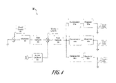
FIG. 4 is a block diagrammatic view of a power distribution system 80 according to another embodiment of the invention. In contrast to the foregoing embodiment, the system 80 is configured to be coupled to a single-phase power source 82, which may comprise a single distribution leg of a three-phase power source, such as an aircraft alternator, or other single-phase power sources. A modulator 84 is coupled to the single-phase power source 82 and receives an input waveform, which is generally a 400 Hz sine wave having a time-varying amplitude. The output waveform from the modulator 84 thus includes a high frequency carrier component having, in one embodiment, a frequency of approximately about 100 kHz and having a wave shape that modulates the input waveform, as previously described.
The system 80 also includes a filter network 86 that generally includes any passive filter configuration operable to suppress the higher order odd-harmonics present in the wave output from the modulator 84. Alternately, the filter network 86 may include an active filter device to operably provide the desired suppression of the higher-order harmonic content present in the wave output from the modulator 84. A mixing unit 88 is coupled to the filter unit 86 and is further coupled to a signal oscillator 90 that are receives a signal 92 and frequency modulates the output waveform from the filter network 86 so that the waveform has a frequency modulated pulse. The generated waveform is transferred to a transformer 94 that is operable to increase or decrease an amplitude of the received waveform. Alternately, the amplitude of the frequency-modulated waveform may be generally unchanged by the transformer 94. Demodulators 96 a, 96 b and 96 c are coupled to the transformer 94 that receive the frequency-modulated waveform and demodulates received waveform. Although FIG. 4 shows three demodulators coupled to the filter network 94, it is understood that one, two or more than three demodulators may be coupled to the transformer 94. In any case, the frequency-modulated pulses are detected in the demodulators 96 a, 96 b and 96 c, which may control power to electrical loads 100 a, 100 b and 100 c, as described in detail in connection with the previous embodiment. Regulators 98 a, 98 b and 98 c are coupled to the demodulators 96 a, 96 b and 96 c to regulate at least one of power, voltage and current delivered to the loads 100 a, 100 b and 100 c.
FIG. 5 is a schematic waveform representation 110 that will be used to qualitatively describe the operation of the power distribution system 80. Referring still to FIG. 4, an input waveform 112 is received from the power source 82, which is a generally sinusoidal waveform having, in one embodiment, a frequency of approximately about 400 Hz. The waveform 52 includes a first portion 114 having a first amplitude, and a second portion 116 having a second amplitude that differs from the first amplitude. Following modulation of the waveform 112 in the modulator 84, a modulated waveform 118 is generated having a selected carrier frequency. The carrier frequency ranges between approximately 40 kHz and approximately about 150 kHz. The modulated waveform 118 also includes a first portion 120 and a second portion 122 having amplitudes generally corresponding to the first portion 114 and the second portion 116 of the waveform 112.
The waveform 118 is then filtered in the filter network 86 so that a sinusoidal waveform 124 is obtained having a selected spectral content. The waveform 124 includes a first portion 126 and a second portion 128 having different amplitudes that correspond to the first portion 120 and the second portion 122 of the waveform 118. The waveform 124 then passes through the mixing unit 88 so that a waveform 130 having a frequency-modulated component 132 is generated. The component 132 is introduced by the signal oscillator 90 in response to the signal 92. The waveform 130 is then introduced into the transformer to yield the waveform 134, which is generally a replication of the waveform 130. It is understood, however, that the waveform 134 may also be reduced in amplitude relative to the waveform 130, or it may have approximately the same amplitude, depending on the turns ratio of the transformer 94.
With reference still to FIG. 5, a waveform 136 results from the demodulation of the waveform 134 in a selected one of the demodulators 96 a, 96 b and 96 c, as previously described. The demodulated waveform 136 may then be regulated in order to obtain a relatively constant amplitude in terms of voltage, current and power.
Those skilled in the art will also readily recognize that the foregoing embodiments may be incorporated into a wide variety of different systems. Referring now in particular to FIG. 6, a side elevation view of an aircraft 300 having one or more of the disclosed embodiments of the present invention is shown. With the exception of the embodiments according to the present invention, the aircraft 300 includes components and subsystems generally known in the pertinent art, and in the interest of brevity, will not be described in detail. The aircraft 300 generally includes one or more propulsion units 302 that are coupled to wing assemblies 304, or alternately, to a fuselage 306 or even other portions of the aircraft 300. Additionally, the aircraft 300 also includes a tail assembly 308 and a landing assembly 310 coupled to the fuselage 306. The aircraft 300 further includes other systems and subsystems generally required for the proper operation of the aircraft 300. For example, the aircraft 300 includes a flight control system 312 (not shown in FIG. 6), as well as a plurality of other electrical, mechanical and electromechanical systems that cooperatively perform a variety of tasks necessary for the operation of the aircraft 300. Accordingly, the aircraft 300 is generally representative of a commercial passenger aircraft, which may include, for example, the 737, 747, 757, 767 and 777 commercial passenger aircraft available from The Boeing Company of Chicago, Ill. Although the aircraft 300 shown in FIG. 6 generally shows a commercial passenger aircraft, it is understood that the various embodiments of the present invention may also be incorporated into flight vehicles of other types. Examples of such flight vehicles may include manned or even unmanned military aircraft, rotary wing aircraft, or even ballistic flight vehicles, as illustrated more fully in various descriptive volumes, such as Jane's All The World's Aircraft, available from Jane's Information Group, Ltd. of Coulsdon, Surrey, UK.
With reference still to FIG. 6, the aircraft 300 may include one or more of the embodiments of the electrical power regulation and distribution system 314 according to the present invention, which may operate in association with the various systems and sub-systems of the aircraft 300. Although the foregoing embodiments of the invention relate specifically to aircraft systems, it is understood that electrical power generation systems are nevertheless present in other types of vehicles, including various forms of terrestrial vehicles such as ground and marine vehicles, which may utilize the various embodiments of the present invention without significant modification. Furthermore, it is understood that the various embodiments of the present invention may also be employed in stationary power generation systems.
While preferred and alternate embodiments of the invention have been illustrated and described, as noted above, many changes can be made without departing from the spirit and scope of the invention. Accordingly, the scope of the invention is not limited by the disclosure of these preferred and alternate embodiments. Instead, the invention should be determined entirely by reference to the claims that follow.