US7352586B2 - Auxiliary supporting structure of circuit board and assembling method for the same - Google Patents

Auxiliary supporting structure of circuit board and assembling method for the same Download PDF

Info

Publication number
US7352586B2
US7352586B2 US11/208,610 US20861005A US7352586B2 US 7352586 B2 US7352586 B2 US 7352586B2 US 20861005 A US20861005 A US 20861005A US 7352586 B2 US7352586 B2 US 7352586B2
Authority
US
United States
Prior art keywords
circuit board
buffer body
heat sink
supporting structure
housing
Prior art date
Legal status (The legal status is an assumption and is not a legal conclusion. Google has not performed a legal analysis and makes no representation as to the accuracy of the status listed.)
Active, expires
Application number
US11/208,610
Other versions
US20060044764A1 (en
Inventor
Yen Kuang
Yang Tzung Lien
Current Assignee (The listed assignees may be inaccurate. Google has not performed a legal analysis and makes no representation or warranty as to the accuracy of the list.)
Asustek Computer Inc
Original Assignee
Asustek Computer Inc
Priority date (The priority date is an assumption and is not a legal conclusion. Google has not performed a legal analysis and makes no representation as to the accuracy of the date listed.)
Filing date
Publication date
Application filed by Asustek Computer Inc filed Critical Asustek Computer Inc
Assigned to ASUSTEK COMPUTER INC. reassignment ASUSTEK COMPUTER INC. ASSIGNMENT OF ASSIGNORS INTEREST (SEE DOCUMENT FOR DETAILS). Assignors: KUANG, YEN, LIEN, YANG TZUNG
Publication of US20060044764A1 publication Critical patent/US20060044764A1/en
Application granted granted Critical
Publication of US7352586B2 publication Critical patent/US7352586B2/en
Active legal-status Critical Current
Adjusted expiration legal-status Critical

Links

Images

Classifications

    • HELECTRICITY
    • H01ELECTRIC ELEMENTS
    • H01LSEMICONDUCTOR DEVICES NOT COVERED BY CLASS H10
    • H01L23/00Details of semiconductor or other solid state devices
    • H01L23/34Arrangements for cooling, heating, ventilating or temperature compensation ; Temperature sensing arrangements
    • H01L23/40Mountings or securing means for detachable cooling or heating arrangements ; fixed by friction, plugs or springs
    • H01L23/4006Mountings or securing means for detachable cooling or heating arrangements ; fixed by friction, plugs or springs with bolts or screws
    • GPHYSICS
    • G06COMPUTING; CALCULATING OR COUNTING
    • G06FELECTRIC DIGITAL DATA PROCESSING
    • G06F1/00Details not covered by groups G06F3/00 - G06F13/00 and G06F21/00
    • G06F1/16Constructional details or arrangements
    • G06F1/18Packaging or power distribution
    • G06F1/183Internal mounting support structures, e.g. for printed circuit boards, internal connecting means
    • HELECTRICITY
    • H01ELECTRIC ELEMENTS
    • H01LSEMICONDUCTOR DEVICES NOT COVERED BY CLASS H10
    • H01L23/00Details of semiconductor or other solid state devices
    • H01L23/34Arrangements for cooling, heating, ventilating or temperature compensation ; Temperature sensing arrangements
    • H01L23/40Mountings or securing means for detachable cooling or heating arrangements ; fixed by friction, plugs or springs
    • H01L23/4006Mountings or securing means for detachable cooling or heating arrangements ; fixed by friction, plugs or springs with bolts or screws
    • H01L2023/4037Mountings or securing means for detachable cooling or heating arrangements ; fixed by friction, plugs or springs with bolts or screws characterised by thermal path or place of attachment of heatsink
    • H01L2023/405Mountings or securing means for detachable cooling or heating arrangements ; fixed by friction, plugs or springs with bolts or screws characterised by thermal path or place of attachment of heatsink heatsink to package
    • HELECTRICITY
    • H01ELECTRIC ELEMENTS
    • H01LSEMICONDUCTOR DEVICES NOT COVERED BY CLASS H10
    • H01L23/00Details of semiconductor or other solid state devices
    • H01L23/34Arrangements for cooling, heating, ventilating or temperature compensation ; Temperature sensing arrangements
    • H01L23/40Mountings or securing means for detachable cooling or heating arrangements ; fixed by friction, plugs or springs
    • H01L23/4006Mountings or securing means for detachable cooling or heating arrangements ; fixed by friction, plugs or springs with bolts or screws
    • H01L2023/4037Mountings or securing means for detachable cooling or heating arrangements ; fixed by friction, plugs or springs with bolts or screws characterised by thermal path or place of attachment of heatsink
    • H01L2023/4062Mountings or securing means for detachable cooling or heating arrangements ; fixed by friction, plugs or springs with bolts or screws characterised by thermal path or place of attachment of heatsink heatsink to or through board or cabinet
    • HELECTRICITY
    • H01ELECTRIC ELEMENTS
    • H01LSEMICONDUCTOR DEVICES NOT COVERED BY CLASS H10
    • H01L23/00Details of semiconductor or other solid state devices
    • H01L23/34Arrangements for cooling, heating, ventilating or temperature compensation ; Temperature sensing arrangements
    • H01L23/40Mountings or securing means for detachable cooling or heating arrangements ; fixed by friction, plugs or springs
    • H01L23/4006Mountings or securing means for detachable cooling or heating arrangements ; fixed by friction, plugs or springs with bolts or screws
    • H01L2023/4075Mechanical elements
    • H01L2023/4081Compliant clamping elements not primarily serving heat-conduction
    • HELECTRICITY
    • H01ELECTRIC ELEMENTS
    • H01LSEMICONDUCTOR DEVICES NOT COVERED BY CLASS H10
    • H01L23/00Details of semiconductor or other solid state devices
    • H01L23/34Arrangements for cooling, heating, ventilating or temperature compensation ; Temperature sensing arrangements
    • H01L23/40Mountings or securing means for detachable cooling or heating arrangements ; fixed by friction, plugs or springs
    • H01L23/4006Mountings or securing means for detachable cooling or heating arrangements ; fixed by friction, plugs or springs with bolts or screws
    • H01L2023/4075Mechanical elements
    • H01L2023/4087Mounting accessories, interposers, clamping or screwing parts
    • HELECTRICITY
    • H01ELECTRIC ELEMENTS
    • H01LSEMICONDUCTOR DEVICES NOT COVERED BY CLASS H10
    • H01L2924/00Indexing scheme for arrangements or methods for connecting or disconnecting semiconductor or solid-state bodies as covered by H01L24/00
    • H01L2924/0001Technical content checked by a classifier
    • H01L2924/0002Not covered by any one of groups H01L24/00, H01L24/00 and H01L2224/00

Definitions

  • the assembling method of the invention further includes the step of installing an insulating slice (S 50 ) between the circuit board 23 and the buffer body 21 . Therefore, the buffer body 21 and the circuit board 23 are not in direct contact to form a short circuit.
  • the assembling method of the invention further includes the step of installing a pad (S 60 ) between the buffer body 21 and the circuit board 23 .
  • the pad 29 indirectly imposes a force on the circuit board 23 to ensure a tight connection between the CPU 231 and the heat sink 24 .
  • the pad 29 may further alleviate the weight of the heat sink 24 .

Abstract

An auxiliary supporting structure of a circuit board is for supporting at least one part of the circuit board. The circuit board has a CPU socket for connected to a CPU, and a through hole through which a heat sink fixing element passes. The auxiliary supporting structure includes a buffer body and a supporting element. In this case, the buffer body is disposed on a housing and has a first surface facing the circuit board. The buffer body is positioned between the circuit board and the housing. The supporting element is disposed on the buffer body and faces the through hole. The heat sink fixing element passes through the through hole and is fixed to the supporting element. An assembling method for the auxiliary supporting structure of the circuit board is provided.

Description

BACKGROUND OF THE INVENTION
1. Field of Invention
The invention relates to a supporting structure and the assembling method thereof. In particular, the invention relates to an auxiliary supporting structure of a circuit board and an assembling method thereof.
2. Related Art
The central processing unit (CPU) mostly determines the performance of a computer. Therefore, it is a marketing trend to provide the high-frequency and high-speed CPU.
However, the high-frequency and high-speed CPU generates more heat that increases the internal temperature of the computer. The high temperature seriously threatens the stability of the CPU operation. For ensuring the normal operation of the CPU, heat has to be removed in time. A common method is to install a heat sink on the surface of the CPU for removing the heat it generates.
A conventional heat sink fixing element 10 provides a mechanism for tying a heat sink 11 and a CPU 12 tightly. As shown in FIG. 1, the heat sink fixing element 10 has a base 13. Each edge of the base 13 has at least one protruding screw boss 14, and a protruding pad 131 is set at the center of the base 13.
Moreover, the base 13 is provided with an insulating slice 15 to prevent the base 13 from directly contacting a circuit board 16 and resulting in a short circuit. The screw boss 14 passes through the heat sink 11, the insulating slice 15, the circuit board 16, and the base 13, and fixes with a screw 17 (as shown in FIG. 2). Thus, the heat sink 11 can be tightly pressed against the CPU 12 on the circuit board 16. The pad 131 at the center of the base 13 is pressed against the bottom of the CPU 12, ensuring that the CPU 12 contacts the heat sink 11 tightly to increase the heat dissipation efficiency of the CPU 12. Moreover, the circuit board 16 is installed on a computer housing 19 by using several second screws 18.
Since a metal heat sink 11 is generally heavy, it may impose a large strain on the CPU 12 attached to the heat sink 11. Resulting in the CPU 12 exerts pressure to deform the circuit board 16 and may even cause the internal circuit, the through hole on the circuit board 16, or the base to break.
It is therefore an important subjective of the invention to provide an auxiliary supporting structure of a circuit board and an assembling method for an auxiliary supporting structure, which can solve the above-mentioned problem of carrying the heat sink.
SUMMARY OF THE INVENTION
In view of the foregoing, the invention is to provide an auxiliary supporting structure of a circuit board to help supporting the weight of a heat sink and the assembling method thereof.
To achieve the above, an auxiliary supporting structure of a circuit board supports at least one part of the circuit board. The circuit board has a CPU socket for connecting to a CPU, and a through hole for receiving a heat sink fixing element. The auxiliary supporting structure includes a buffer body and a supporting element. In this case, the buffer body is disposed on a housing and has a first surface facing the circuit board. The buffer body is positioned between the circuit board and the housing. The supporting element is disposed on the buffer body and faces the through hole. The heat sink fixing element passes through the through hole and is fixed to the supporting element.
An assembling method for an auxiliary supporting structure of a circuit board is also disclosed, which includes the following steps: aligning a positioning tool on a housing; attaching a buffer body to the housing; removing the positioning tool from the housing; fixing a circuit board on the housing; installing a CPU on the circuit board; and inserting a heat sink fixing element through a heat sink and a circuit board to fix the heat sink fixing element on a supporting element so as to fix the heat sink on the CPU.
As mentioned above, the auxiliary supporting structure of the circuit board and the method for the same install a buffer body on a housing. Comparing to the prior art, a buffer body for a supporting element is installed on the housing in this invention to help supporting the circuit board and the weight of the heat sink in tight contact with the CPU on the circuit board. Since the buffer body is disposed on the housing that is firmer, the weight of the heat sink is distributed to the housing without deforming the circuit board or breaking the internal circuit, the through hole, or the buffer body. Therefore, the quality of the products is improved. Moreover, in an embodiment of the invention, the auxiliary supporting structure of the circuit board can further includes an adjusting element to connect the heat sink fixing element and the supporting element of different lengths, increasing the compatibility of the supporting structure of the circuit board of the invention with different types of heat sinks. In the assembling method of the invention, the positioning tool has several sets of through holes for different types of heat sinks to align with the positioning elements on the housing for a better compatibility. Furthermore, the auxiliary supporting structure of the circuit board can include a pad or an elastic slice on the buffer body to press against the circuit board. This ensures a tight attachment of the CPU on the heat sink to improve the heat dissipation efficiency.
BRIEF DESCRIPTION OF THE DRAWINGS
The invention will become more fully understood from the detailed description given herein below illustration only, and thus is not limitative of the present invention, and wherein:
FIG. 1 is a schematic view showing the conventional heat sink fixing element;
FIG. 2 is a schematic cross-sectional view of the conventional heat sink fixing element in connection;
FIG. 3 is a schematic view of an auxiliary supporting structure of a circuit board according to a preferred embodiment of the invention;
FIG. 4 is a schematic view showing the connection of the auxiliary supporting structure of the circuit board according to the preferred embodiment of the invention;
FIG. 5 is a schematic view showing the connection of another auxiliary supporting structure of the circuit board according to the preferred embodiment of the invention;
FIG. 6 is a schematic view showing the connection of still another auxiliary supporting structure of the circuit board according to the preferred embodiment of the invention;
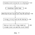
FIG. 7 is a flow chart showing an assembling method for the auxiliary supporting structure of the circuit board according to the preferred embodiment of the invention;
FIG. 8 is a schematic view showing the installation of a positioning tool according to the assembling method for the auxiliary supporting structure of the circuit board; and
FIG. 9 is a flow chart showing another assembling method for the auxiliary supporting structure of the circuit board according to the preferred embodiment of the invention.
DETAILED DESCRIPTION OF THE INVENTION
The present invention will be apparent from the following detailed description, which proceeds with reference to the accompanying drawings, wherein the same references relate to the same elements.
FIGS. 3 to 6 are for illustrating an auxiliary supporting structure of a circuit board according to a preferred embodiment of the invention.
With reference to FIG. 3, an auxiliary supporting structure 20 includes a buffer body 21 and a supporting element 22. The auxiliary supporting structure 20 is used to support at least one part of a circuit board 23. The circuit board 23 has a CPU socket for the connection of a CPU 231 and a through hole 233 through which a heat sink fixing element 241 passes.
In this embodiment, the heat sink fixing element 241 fixes a heat sink 24 on the CPU 231 to help removing heat from the CPU 231. Thus, the CPU 231 does not become unstable because of overheating.
Referring to FIGS. 3 and 4, the buffer body 21 is installed on a housing 25. A first surface 211 of the buffer body 21 faces the circuit board 23. The buffer body 21 is positioned between the circuit board 23 and the housing 25.
In this embodiment, the auxiliary supporting structure 20 further includes an adhesive 26 on a second surface 212 of the buffer body 21. The adhesive 26 is for combining the buffer body 21 and the housing 25.
As shown in FIGS. 3 and 4, the supporting element 22 is installed on the buffer body 21 and faces the through hole 233. The heat sink fixing element 241 goes through the through hole 233 and is fixed to the supporting element 22. In this embodiment, the heat sink fixing element 241 is a screw and the supporting element 22 is a screw boss formed together with the buffer body 21. Moreover, as shown in FIG. 5, the supporting element 22 can be a combination of a bolt and a nut. The bolt goes through the housing 25 and combines with the nut.
With reference to FIG. 6, the auxiliary supporting structure 20 of the present embodiment also includes an adjusting element 221 disposed between the supporting element 22 and the heat sink fixing element 241 to fix the supporting element 22 and the heat sink fixing element 241. In this case, the adjusting element 221 is a screw with a screw hole. One end of the adjusting element 221 connects to the heat sink fixing element 241, while the other end thereof connects to the supporting element 22. Using the adjusting element 221, the heat sink fixing element 241 and the supporting element 22 are firmly connected. Hence, the heat sink fixing element 241 will not be unable to connect with the supporting element 22 because its length is too short. Thus, the adjusting element 221 increases the compatibility between the heat sink 24 and the buffer body 21.
Referring to FIG. 4 again, the auxiliary supporting structure 20 further includes an elastic slice 27 disposed between the buffer body 21 and the circuit board 23. The elastic slice 27 pushes upward against the circuit board 23 to ensure tight contact of the CPU 231 and the heat sink 24. Of course, the elastic slice 27 can be replaced by a spring. The material of the elastic slice 27 can be metal or plastic.
As shown in FIG. 4, the auxiliary supporting structure 20 further includes an insulating slice 28 disposed between the buffer body 21 and the circuit board 23, so that they are not in direct contact to form a short circuit. In this embodiment, the insulating slice 28 is installed on the elastic slice 27. If the insulating slice 28 is a soft thin sheet, a hard board 28′ can be added to support the insulating. slice 28.
With reference to FIGS. 5 and 6, the auxiliary supporting structure 20 further includes a pad 29 disposed between the buffer body 21 and the circuit board 23. The pad 29 presses upward against the circuit board 23 to ensure tight contact of the CPU 231 and the heat sink 24. The pad 29 can further buffer the weight of the heat sink 24.
Using the buffer body 21 installed on the housing 25 and the supporting element 22 connected to the heat sink fixing element 241, the weight of the heat sink 24 can be distributed to the firmer housing 25, preventing the circuit board 23 and the through hole 233 from deforming or breaking.
FIGS. 3 to 9 show an assembling method for the auxiliary supporting structure of the circuit board according to the preferred embodiment of the invention.
Hereinafter, the elements with the same references as referred in the previously mentioned embodiment have the same functions and features, so the detailed descriptions are omitted for concise purpose.
As shown in FIG. 7, the assembling method includes the steps of aligning a positioning tool on a housing (S10), attaching a buffer body (S20), removing the positioning tool from the housing (S30), fixing a circuit board on the housing (S80), and making a heat sink fixing element go through a heat sink and the circuit board (S90).
With reference to FIGS. 7 and 8, in step S10, several positioning holes 31 on the positioning tool 30 are aligned with several positioning elements 251 of the housing 25. Besides, the positioning tool 30 has an opening 32 to define the installation position of the buffer body 21. As shown in FIGS. 3 and 8, different types of circuit boards 23 occupy different positions when they are installed on the housing 25, and the positioning tool 30 thus has several sets of through holes 31 for them. This helps increasing the compatibility of the auxiliary supporting structure.
With reference to FIGS. 4, 7 and 9, in step S20, the buffer body 21 is attached to the housing 25. In this embodiment, the assembling method also includes the step of providing an adhesive (S21) to attach the second surface 212 of the buffer body 21 to the housing 25.
With reference to FIGS. 8 and 9, step S30 is to remove the positioning tool 30 from the housing 25.
With reference to FIGS. 4 and 9, in this embodiment, the assembling method for the auxiliary supporting structure of the circuit board further includes the step of installing an elastic slice (S40) on a first surface 211 of the buffer body 21 by, for example, a screw. The elastic slice 27 indirectly imposes a force on the circuit board 23 to ensure a tight connection between the CPU 231 and the heat sink 24.
With reference to FIGS. 4 and 9, the assembling method of the invention further includes the step of installing an insulating slice (S50) between the circuit board 23 and the buffer body 21. Therefore, the buffer body 21 and the circuit board 23 are not in direct contact to form a short circuit.
With reference to FIGS. 5 and 9, the assembling method of the invention further includes the step of installing a pad (S60) between the buffer body 21 and the circuit board 23. The pad 29 indirectly imposes a force on the circuit board 23 to ensure a tight connection between the CPU 231 and the heat sink 24. The pad 29 may further alleviate the weight of the heat sink 24.
With reference to FIGS. 4, 5 and 9, in this embodiment, the assembling method also includes the step of installing at least one supporting element on the buffer body (S70). In this case, at least one supporting element 22 is installed on the buffer body 21 and may be the combination of a nut and bolt or a screw boss.
As shown in FIGS. 3 and 7, when fixing a circuit board on the housing (S80), a circuit board 23 is locked by a screw on the housing 25. The circuit board 23 has a CPU 231 installed thereon through a CPU socket 232.
As shown in FIGS. 3 and 7, a heat sink fixing element goes through the heat sink and the circuit board (S90) so as to be fixed with the supporting element 22. The heat sink 24 is thus fixed on the CPU 231.
With reference to FIGS. 6 and 9, in this embodiment, the assembling method further includes the step of installing an adjusting element (S100) between the supporting element 22 and the heat sink fixing element 241. The adjusting element 211 may be a screw with a screw hole, having one end connected to the heat sink fixing element 241 and the other end connected to the supporting element 22.
In summary, the auxiliary supporting structure of the circuit board and the method for the same install a buffer body on a housing. Comparing to the prior art, a buffer body for a supporting element is installed on the housing in this invention to help supporting the circuit board and the weight of the heat sink in tight contact with the CPU on the circuit board. Since the buffer body is disposed on the housing that is firmer, the weight of the heat sink is distributed to the housing without deforming the circuit board or breaking the internal circuit, the through hole, or the buffer body. Therefore, the quality of the products is improved. Moreover, in an embodiment of the invention, the auxiliary supporting structure of the circuit board can further includes an adjusting element to connect the heat sink fixing element and the supporting element of different lengths, increasing the compatibility of the supporting structure of the circuit board of the invention with different types of heat sinks. In the assembling method of the invention, the positioning tool has several sets of through holes for different types of heat sinks to align with the positioning elements on the housing for a better compatibility. Furthermore, the auxiliary supporting structure of the circuit board can include a pad or an elastic slice on the buffer body to press against the circuit board. This ensures a tight attachment of the CPU on the heat sink to improve the heat dissipation efficiency.
Although the invention has been described with reference to specific embodiments, this description is not meant to be construed in a limiting sense. Various modifications of the disclosed embodiments, as well as alternative embodiments, will be apparent to persons skilled in the art. It is, therefore, contemplated that the appended claims will cover all modifications that fall within the true scope of the invention.

Claims (14)

1. An auxiliary supporting structure of a circuit board to support at least one part of the circuit board in a housing, the circuit board having a central processing unit (CPU) socket for connecting with a CPU and a through hole for a heat sink fixing element to pass through, the auxiliary supporting structure comprising:
a buffer body located between the circuit board and the housing and has a first surface facing the circuit board and a second surface;
an adhesive disposed on the second surface of the buffer body for connecting the housing and the buffer; and
a supporting element installed on the buffer body and corresponding to the through hole, wherein the heat sink fixing element passes through the through hole to connect with the supporting element.
2. The auxiliary supporting structure of claim 1, wherein the heat sink fixing element fixes a heat sink on the CPU.
3. The auxiliary supporting structure of claim 1, wherein the supporting element comprises an adjusting element connected to the heat sink fixing element for fastening the heat sink fixing element to the supporting element.
4. The auxiliary supporting structure of claim 1, wherein the supporting element and the buffer body are integrally formed.
5. The auxiliary supporting structure of claim 1, further comprising:
a pad, wherein one side of the pad connects to the buffer body, and the other side of the pad connects to the circuit board.
6. The auxiliary supporting structure of claim 1, further comprising:
an elastic slice, wherein one side of the elastic slice connects to the buffer body, and the other side of the elastic slice connects to the circuit board.
7. The auxiliary supporting structure of claim 1, further comprising:
an insulating slice, wherein one side of the insulating slice connects to the buffer body, and the other side of the insulating slice connects to the circuit board.
8. An assembling method for an auxiliary supporting structure of a circuit board, comprising:
attaching a buffer body with an adhesive disposed on one side of the buffer body to a supporting element on the housing;
fixing a circuit board installed with a CPU on the housing; and
inserting a heat sink fixing element through a heat sink and the circuit board to connect with the supporting element, wherein the heat sink is disposed on the CPU.
9. The assembling method of a claim 8, further comprising:
aligning a positioning tool on a housing, wherein the positioning tool has a plurality of through holes for aligning with a plurality of positioning elements of the housing, so that the positioning tool properly positions the buffer body on the housing.
10. The assembling method of claim 9, wherein the positioning tool has an opening to define the location of the buffer body.
11. The assembling method of claim 8, further comprising:
installing an elastic slice on a first surface of the buffer body.
12. The assembling method of claim 8, further comprising:
installing a pad on a first surface of the buffer body.
13. The assembling method of claim 8, further comprising:
installing an insulating slice between the circuit board and the buffer body wherein one side of the insulating slice connects to the circuit board and the other side of the insulating slice connects to the buffer body.
14. The assembling method of claim 8, wherein the supporting element comprises an adjusting element connected to the heat sink fixing element for fastening the heat sink fixing element to the supporting element.
US11/208,610 2004-08-26 2005-08-23 Auxiliary supporting structure of circuit board and assembling method for the same Active 2026-04-21 US7352586B2 (en)

Applications Claiming Priority (2)

Application Number Priority Date Filing Date Title
TW093125637 2004-08-26
TW093125637A TWI255684B (en) 2004-08-26 2004-08-26 Auxiliary supporting structure of circuit board and assembling method for the same

Publications (2)

Publication Number Publication Date
US20060044764A1 US20060044764A1 (en) 2006-03-02
US7352586B2 true US7352586B2 (en) 2008-04-01

Family

ID=35942740

Family Applications (1)

Application Number Title Priority Date Filing Date
US11/208,610 Active 2026-04-21 US7352586B2 (en) 2004-08-26 2005-08-23 Auxiliary supporting structure of circuit board and assembling method for the same

Country Status (2)

Country Link
US (1) US7352586B2 (en)
TW (1) TWI255684B (en)

Cited By (8)

* Cited by examiner, † Cited by third party
Publication number Priority date Publication date Assignee Title
US20090056918A1 (en) * 2007-08-27 2009-03-05 Fu Zhun Precision Industry (Shen Zhen) Co., Ltd. Heat dissipation device having a back plate unit
US20090221162A1 (en) * 2008-03-03 2009-09-03 Hon Hai Precision Ind. Co., Ltd. Socket assembly with backplane
US20100097761A1 (en) * 2008-10-16 2010-04-22 Hon Hai Precision Industry Co., Ltd. Motherboard
US20190252813A1 (en) * 2018-02-09 2019-08-15 Foxconn (Kunshan) Computer Connector Co., Ltd. Connector equipped with spring retention mechanism
US10790215B1 (en) * 2019-05-27 2020-09-29 Cooler Master Technology Inc. Heat dissipation device
US11195779B2 (en) 2019-08-09 2021-12-07 Raytheon Company Electronic module for motherboard
US20220078924A1 (en) * 2020-09-10 2022-03-10 Lenovo (Singapore) Pte. Ltd. Electronic apparatus and structure
US20230004200A1 (en) * 2021-07-01 2023-01-05 Portwell Inc. Board device of single board computer

Families Citing this family (9)

* Cited by examiner, † Cited by third party
Publication number Priority date Publication date Assignee Title
US7609525B2 (en) * 2006-12-09 2009-10-27 Hon Hai Precision Industry Co., Ltd. Computer system
JP5163543B2 (en) * 2009-03-03 2013-03-13 富士通株式会社 Printed circuit board unit
CN102117111A (en) * 2010-01-04 2011-07-06 鸿富锦精密工业(深圳)有限公司 Heat dissipation module for main board
US8619420B2 (en) * 2011-06-30 2013-12-31 Apple Inc. Consolidated thermal module
US9379037B2 (en) 2014-03-14 2016-06-28 Apple Inc. Thermal module accounting for increased board/die size in a portable computer
US10522443B2 (en) * 2017-06-05 2019-12-31 Microsemi Corporation Lid cover spring design
CN113473786B (en) * 2021-06-08 2022-09-13 合肥磐芯电子有限公司 Singlechip antidetonation is from preserving protection integral structure
CN117598034A (en) * 2021-10-20 2024-02-23 华为技术有限公司 Circuit board assembly, electronic equipment and bracket
CN114025579A (en) * 2021-11-16 2022-02-08 北京卫星制造厂有限公司 Compressing heat dissipation device

Citations (10)

* Cited by examiner, † Cited by third party
Publication number Priority date Publication date Assignee Title
US5607538A (en) * 1995-09-07 1997-03-04 Ford Motor Company Method of manufacturing a circuit assembly
US5999402A (en) * 1997-10-28 1999-12-07 Dell Usa, L.P. Heat sink fastener retention apparatus and method for computer systems
US6226179B1 (en) * 1998-10-17 2001-05-01 Samsung Electronics Co., Ltd. Mounting structure of a semiconductor device module for a computer system
US6549410B1 (en) * 2001-11-20 2003-04-15 Hewlett-Packard Company Heatsink mounting system
US6639804B1 (en) * 2002-06-28 2003-10-28 Hon Hai Precision Ind. Co., Ltd. Adjustable device for heat sink retention module
US6717815B2 (en) * 2001-07-11 2004-04-06 Quanta Computer, Inc. Heat dissipation module and its fixed member
US20050068741A1 (en) * 2003-09-29 2005-03-31 Bailey Douglas A. System and method for mounting processor and heat transfer mechanism
US20050214784A1 (en) * 2001-06-30 2005-09-29 Enzo Life Sciences, Inc. Processes for detecting or quantifying nucleic acids using an array of fixed or immobilized nucleic acids
US7042727B2 (en) * 2003-09-26 2006-05-09 Intel Corporation Heat sink mounting and interface mechanism and method of assembling same
US7120027B2 (en) * 2004-07-08 2006-10-10 Cray Inc. Assemblies for mounting electronic devices and associated heat sinks to computer modules and other structures

Patent Citations (10)

* Cited by examiner, † Cited by third party
Publication number Priority date Publication date Assignee Title
US5607538A (en) * 1995-09-07 1997-03-04 Ford Motor Company Method of manufacturing a circuit assembly
US5999402A (en) * 1997-10-28 1999-12-07 Dell Usa, L.P. Heat sink fastener retention apparatus and method for computer systems
US6226179B1 (en) * 1998-10-17 2001-05-01 Samsung Electronics Co., Ltd. Mounting structure of a semiconductor device module for a computer system
US20050214784A1 (en) * 2001-06-30 2005-09-29 Enzo Life Sciences, Inc. Processes for detecting or quantifying nucleic acids using an array of fixed or immobilized nucleic acids
US6717815B2 (en) * 2001-07-11 2004-04-06 Quanta Computer, Inc. Heat dissipation module and its fixed member
US6549410B1 (en) * 2001-11-20 2003-04-15 Hewlett-Packard Company Heatsink mounting system
US6639804B1 (en) * 2002-06-28 2003-10-28 Hon Hai Precision Ind. Co., Ltd. Adjustable device for heat sink retention module
US7042727B2 (en) * 2003-09-26 2006-05-09 Intel Corporation Heat sink mounting and interface mechanism and method of assembling same
US20050068741A1 (en) * 2003-09-29 2005-03-31 Bailey Douglas A. System and method for mounting processor and heat transfer mechanism
US7120027B2 (en) * 2004-07-08 2006-10-10 Cray Inc. Assemblies for mounting electronic devices and associated heat sinks to computer modules and other structures

Cited By (12)

* Cited by examiner, † Cited by third party
Publication number Priority date Publication date Assignee Title
US20090056918A1 (en) * 2007-08-27 2009-03-05 Fu Zhun Precision Industry (Shen Zhen) Co., Ltd. Heat dissipation device having a back plate unit
US7903419B2 (en) * 2007-08-27 2011-03-08 Fu Zhun Precision Industry (Shen Zhen) Co., Ltd. Heat dissipation device having a back plate unit
US20090221162A1 (en) * 2008-03-03 2009-09-03 Hon Hai Precision Ind. Co., Ltd. Socket assembly with backplane
US7708579B2 (en) * 2008-03-03 2010-05-04 Hon Hai Precision Ind. Co., Ltd. Socket assembly with backplane
US20100097761A1 (en) * 2008-10-16 2010-04-22 Hon Hai Precision Industry Co., Ltd. Motherboard
US20190252813A1 (en) * 2018-02-09 2019-08-15 Foxconn (Kunshan) Computer Connector Co., Ltd. Connector equipped with spring retention mechanism
US10741952B2 (en) * 2018-02-09 2020-08-11 Foxconn (Kunshan) Computer Connector Co., Ltd. Connector equipped with spring retention mechanism
US10790215B1 (en) * 2019-05-27 2020-09-29 Cooler Master Technology Inc. Heat dissipation device
US11195779B2 (en) 2019-08-09 2021-12-07 Raytheon Company Electronic module for motherboard
US20220078924A1 (en) * 2020-09-10 2022-03-10 Lenovo (Singapore) Pte. Ltd. Electronic apparatus and structure
US11751341B2 (en) * 2020-09-10 2023-09-05 Lenovo (Singapore) Pte. Ltd. Electronic apparatus and structure
US20230004200A1 (en) * 2021-07-01 2023-01-05 Portwell Inc. Board device of single board computer

Also Published As

Publication number Publication date
US20060044764A1 (en) 2006-03-02
TWI255684B (en) 2006-05-21
TW200608860A (en) 2006-03-01

Similar Documents

Publication Publication Date Title
US7352586B2 (en) Auxiliary supporting structure of circuit board and assembling method for the same
US7715196B2 (en) Mounting device for chips
US7746646B2 (en) Securing device for assembling heat dissipation module onto electronic component
US7286363B2 (en) Heat dissipation device
US20030159819A1 (en) Heatsink device for cooling chipset
US7336496B1 (en) Fixing structure for computer mainboard
US7639504B2 (en) Mounting device for mounting heat sink onto electronic component
US20030210528A1 (en) Fastening device
US7613005B2 (en) Mounting device for mounting heat sink onto electronic component
US6343013B1 (en) Heat sink assembly
US9030825B2 (en) Springy clip type apparatus for fastening power semiconductor
US20090283243A1 (en) Heat dissipation device
US7167370B2 (en) Fastener for mounting heat-radiator to electronic device
EP1709854A2 (en) System and method for self-leveling heat sink for multiple height devices
US8629555B2 (en) Fixture for semiconductor device and assembly of semiconductor device
US6154365A (en) Spring fixture that attaches a heat sink to a substrate for multiple cycle assembly/disassembly
US6012510A (en) Torsion bar clamp apparatus and method for improving thermal and mechanical contact between stacked electronic components
US6560113B1 (en) Electronic device assembly having thermal module for heat dissipation
US20090201646A1 (en) Retaining device
US6419008B1 (en) CPU cooling device with a mounting mechanism
US6480386B1 (en) Heat sink assembly with pressing wedges
US20210289667A1 (en) Electronic assembly and heat dissipation assembly thereof
US6600652B2 (en) Package retention module coupled directly to a socket
US8546192B2 (en) System for clamping heat sink
CN112068644B (en) Motherboard module and electronic device

Legal Events

Date Code Title Description
AS Assignment

Owner name: ASUSTEK COMPUTER INC., TAIWAN

Free format text: ASSIGNMENT OF ASSIGNORS INTEREST;ASSIGNORS:KUANG, YEN;LIEN, YANG TZUNG;REEL/FRAME:016919/0585

Effective date: 20050810

STCF Information on status: patent grant

Free format text: PATENTED CASE

FPAY Fee payment

Year of fee payment: 4

FPAY Fee payment

Year of fee payment: 8

MAFP Maintenance fee payment

Free format text: PAYMENT OF MAINTENANCE FEE, 12TH YEAR, LARGE ENTITY (ORIGINAL EVENT CODE: M1553); ENTITY STATUS OF PATENT OWNER: LARGE ENTITY

Year of fee payment: 12