US7362656B2 - Ultrasonic locating system - Google Patents
Ultrasonic locating system Download PDFInfo
- Publication number
- US7362656B2 US7362656B2 US10/534,485 US53448505A US7362656B2 US 7362656 B2 US7362656 B2 US 7362656B2 US 53448505 A US53448505 A US 53448505A US 7362656 B2 US7362656 B2 US 7362656B2
- Authority
- US
- United States
- Prior art keywords
- unit
- identification tag
- stationary
- central processing
- ultrasonic
- Prior art date
- Legal status (The legal status is an assumption and is not a legal conclusion. Google has not performed a legal analysis and makes no representation as to the accuracy of the status listed.)
- Active, expires
Links
Images


Classifications
-
- G—PHYSICS
- G01—MEASURING; TESTING
- G01S—RADIO DIRECTION-FINDING; RADIO NAVIGATION; DETERMINING DISTANCE OR VELOCITY BY USE OF RADIO WAVES; LOCATING OR PRESENCE-DETECTING BY USE OF THE REFLECTION OR RERADIATION OF RADIO WAVES; ANALOGOUS ARRANGEMENTS USING OTHER WAVES
- G01S5/00—Position-fixing by co-ordinating two or more direction or position line determinations; Position-fixing by co-ordinating two or more distance determinations
- G01S5/18—Position-fixing by co-ordinating two or more direction or position line determinations; Position-fixing by co-ordinating two or more distance determinations using ultrasonic, sonic, or infrasonic waves
- G01S5/26—Position of receiver fixed by co-ordinating a plurality of position lines defined by path-difference measurements
-
- G—PHYSICS
- G01—MEASURING; TESTING
- G01S—RADIO DIRECTION-FINDING; RADIO NAVIGATION; DETERMINING DISTANCE OR VELOCITY BY USE OF RADIO WAVES; LOCATING OR PRESENCE-DETECTING BY USE OF THE REFLECTION OR RERADIATION OF RADIO WAVES; ANALOGOUS ARRANGEMENTS USING OTHER WAVES
- G01S5/00—Position-fixing by co-ordinating two or more direction or position line determinations; Position-fixing by co-ordinating two or more distance determinations
- G01S5/0009—Transmission of position information to remote stations
- G01S5/0018—Transmission from mobile station to base station
- G01S5/0036—Transmission from mobile station to base station of measured values, i.e. measurement on mobile and position calculation on base station
Definitions
- the invention relates to a method and a system for monitoring and position determination of objects and/or living beings within an area such as, e.g. a room in a building or a road tunnel.
- the system comprises a plurality of electronic units called identification tags, which are attached to the objects to be monitored.
- Each identification tag has its own identification code (ID code) and is equipped with an ultrasonic receiver and radio transmitter.
- the ultrasonic signals it receives are transmitted synchronously from a plurality of transmitter units.
- the ultrasonic receiver in the identification tag is connected with a calculating unit which calculates the arrival time of received ultrasonic signals.
- This information together with the identification tag's ID code and any additional information are transmitted in the form of radio waves to a central processing unit which calculates the identification tag's position and presents it to a user of the system.
- the system according to the invention employs identification tags which are placed on the objects that have to be monitored.
- the identification tags contain both ultrasonic receivers and radio transmitters.
- An identification tag according to the invention is equipped with both an ultrasonic receiver and a radio transmitter.
- the ultrasonic signals it receives are transmitted synchronously from a plurality of transmitter units.
- the ultrasonic receiver in the identification tag is connected with a calculating unit which calculates the arrival time of received ultrasonic signals.
- This information together with the identification tag's ID code etc. are transmitted in the form of radio waves to a central processing unit which calculates the identification tag's position and presents it to a user of the system.
- the ultrasonic receiver in the identification tag can be activated only if ultrasonic signals are to be transmitted in the room or the area in which it is located.
- the system may advantageously be employed in areas which are traditionally used for only radio-based systems or only ultrasound-based systems.
- ultrasound for calling up a single or several tags
- the area in which tags respond will be restricted, while the use of radio waves for transferring the ID code and timing gives the identification tag a high data transfer capacity and makes it insensitive to Doppler shift.
- U.S. Pat. No. 6,317,386 describes a system which combines ultrasonic and radio waves.
- the system works in such a manner that the identification tags are called up by means of radio waves, while the actual communication between transmitter units and base stations is conducted by means of ultrasound.
- the object of this system which is for indoor use, is to increase the capacity of an ultrasound-based system. This is accomplished by periodically calling up each tag, which has a unique address, by means of radio waves.
- the identification of each tag therefore does not need to be transmitted to the base station by means of ultrasound.
- the area of application of this system is restricted, the system requires accurate location of all the receivers in advance and complicated signal processing, and it functions best when there is an unobstructed view between the transmitter and the receivers.
- the present invention is also a system which combines ultrasonic and radio waves.
- the identification tags receive ultrasonic pulses, and the actual communication from the identification tags to a central unit is implemented by means of radio waves.
- U.S. Pat. No. 6,121,926 also describes a system for location of identification tags.
- the tags are attached to objects in a logistics system.
- an identification tag transmits a signal with its identification, it has to be received on 3 or more base stations, where an analysis is made of the arrival time and the position is determined.
- the accuracy of such a system will be a few metres, thus making it difficult to determine which room an object is located in without extensive calibration.
- the cost per base station with antenna for the radio is substantially greater than the cost of the ultrasonic transmitters, even though one ultrasonic transducer often has to be placed in each room.
- U.S. Pat. No. 612,196 essentially describes an improved signal processing method for improving the location of identification tags by distinguishing between direct waves and reflected waves. This requires processing power which is also not required in the present invention.
- the present invention relates to a method and a system for monitoring and position determination of identification tags which can be attached to objects.
- the object of the invention is to provide a flexible system that combines the use of ultrasonic waves and radio waves.
- the system and the method according to the invention make it possible to achieve high data transfer capacity and to measure position regardless of movement.
- the system comprises, more closely described, electronic transmitter units or identification tags for attaching to the objects that have to be monitored.
- Each identification tag is equipped with a radio transmitter and ultrasonic receiver.
- each room is equipped with one or more units which transmit different encoded ultrasonic pulses.
- the transmission of ultrasonic pulses from these stationary units is controlled from a central processing unit which may be a server with which the system is in network connection.
- the stationary units in the system consist of master units and slave units.
- a master unit comprises an ultrasonic transmitter and means for transmitting and receiving synchronisation information.
- the master units may receive synchronisation signals from a central processing unit, e.g. a server. Moreover, they may transmit this synchronisation information to the slave units which are stationary units comprising ultrasonic transmitters and means for receiving the synchronisation information.
- the connection between master units and slave units is either wireless or wire-based. For a wireless connection the use of radio waves is preferred.
- the connection between master units and server may also be wireless or wire-based, where the use of radio waves is preferred.
- each master unit receives control signals from the central processing unit.
- the master unit will then transmit an ultrasonic pulse in the room in which it is located.
- a rough positioning i.e. whether or not there is an identification tag in a room.
- a stationary master unit in each room or area that is connected with a central processing unit, e.g. a server, and at least three slave units connected with the master unit.
- a central processing unit e.g. a server
- slave units connected with the master unit.
- the server successively transmits a message to the master units in each room with which it is connected.
- the master unit will transmit a synchronisation message to slave units with which it is connected.
- the master unit and the slave units will simultaneously transmit an ultrasonic pulse, each encoded in its own way, which is received by the identification tags in room 1.
- Each identification tag will calculate arrival times for received ultrasonic pulses. This information together with the identification tag's ID code is transmitted in the form of radio signals to the server which in turn updates its database with the position of the various identification tags and thereby the object to which they are attached. After the positions of the identification tags in room 1 have been updated, room 2 will be called up, and the same procedure will be carried out until all the rooms included in the system have been examined.
- the identification tags may be equipped with a radio receiver, thus enabling them to intercept the radio waves transmitted from the server to the master unit in the room in which they are located and thereby switch on the ultrasonic receiver for a certain period after receiving the radio waves.
- FIG. 1 illustrates the construction of an identification tag for this system
- FIG. 2 illustrates the construction of a master unit
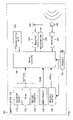
- FIG. 3 illustrates how the whole system is combined in a network.
- the system according to the invention is constructed in such a manner as to obtain high data transfer capacity and insensitivity to Doppler shift.
- transmitter, receiver and central unit that contribute to this. As a whole it represents a system that is well suited to different environments.
- the advantages of the invention are achieved by combining the use of radio waves with ultrasonic waves in the manner described below.
- FIG. 1 illustrates which units may typically be incorporated in each identification tag 100 .
- the identification tag 100 which is intended for use in a location system 400 ( FIG. 3 ) for determining the identification tag's 100 location in a room in a building or areas that require to be monitored, comprises an ultrasonic transducer 190 adapted to receive ultrasonic signals, together with a radio transmitter 170 connected to an antenna 195 for transmitting signals with information containing the identity of the identification tag.
- the ultrasonic transducer 190 is connected to a receiver unit 180 for detecting ultrasonic pulses with different codes (e.g. frequencies, scattered spectrum, etc.) transmitted from one or more master units 200 and slave units 300 ( FIG. 3 ) which transmit on the various frequencies.
- codes e.g. frequencies, scattered spectrum, etc.
- the identification tag 100 further comprises a calculating unit 165 connected to the receiver unit 180 , arranged to calculate transit time differences for the received ultrasonic pulses.
- the calculating unit 165 is further connected to a control unit 160 which coordinates and controls all the signals received by and transmitted from the identification tag 100 .
- the control unit 160 is arranged to cause the radio transmitter 170 to transmit the radio signals in response to the identification chip's 100 calculating unit 165 having calculated transit time differences for all received ultrasonic pulses.
- the identification tag 100 may further consist of a sabotage sensor 110 , which is connected to the control unit 160 , in order to detect any attempt to remove and/or open the identification tag 100 , and where, after such detection, the control unit 160 is adapted to add such additional information to the radio signal transmitted from the identification tag 100 .
- the identification tag 100 may comprise a timer unit 120 , motion detector 130 , identification unit 140 and battery monitor 150 , which monitors the status of the battery 155 .
- the identification tag 100 may also be equipped with a radio receiver 175 connected to an antenna 195 .
- the radio receiver is then connected to the control unit 160 in order to receive the radio signals transmitted in the room or area in which it is located, with the result that the identification tag 100 does not need to listen continuously for ultrasonic signals.
- the identification tag 100 will listen for ultrasonic pulses for a short period after receiving radio signals. Since the ultrasonic receiver requires more power than a radio receiver, this will represent a power saving.
- the tag or identification tag 100 may contain all or only some of the units mentioned here.
- FIG. 2 shows which units may typically be incorporated in a master unit 200 .
- the master unit 200 comprises an ultrasonic transducer 265 for transmitting ultrasonic signals in the form of ultrasonic pulses and a receiver unit depicted as a radio receiver 270 for receiving instructions from at least one central processing unit 410 .
- a radio receiver 270 is illustrated connected to an antenna 295 .
- This type of connection to the central processing unit 410 may be replaced by a typical cabled connection such as, e.g. Ethernet.
- the signals coming into the receiver unit 270 via the antenna 295 are fed to a data demodulator 230 which in turn is connected to a network interface 215 via a controller 210 .
- To this network may be connected corresponding units, preferably slave units 300 .
- the master units use the network to transmit synchronisation information to other connected units in the same room or area.
- the network connection may be wireless (not shown) or wire-based.
- FIG. 3 shows an overview of the whole system 400 according to the invention.
- the figure illustrates the interplay between master units 200 , slave units 300 , identification tags 100 and a central unit 410 in the form of a server that processes all received data.
- client terminals 420 may also be coupled to the system in order to gain access to information from different locations.
- a system 400 for position determination of at least one identification tag 100 comprising:
- the system further comprises at least one stationary slave unit 300 with an ultrasonic transducer for transmitting ultrasonic signals in the form of ultrasonic pulses.
- the system comprises one master unit 200 and at least three slave units 300 .
- the network 215 further interconnects stationary master units 200 and slave units 300 for transfer of a synchronisation message from the master unit 200 .
- the stationary master units 200 and the slave units 300 each transmit ultrasonic waves on their own frequencies and with their own coding.
- the master units 200 comprise means 210 , 230 for transmitting a synchronisation message to all stationary slave units 300 with which they are connected via a network.
- connection between master units 200 and the central processing unit 410 may be based on radio waves or be wire-based.
- the stationary slave units 300 comprise means for receiving a synchronisation message from stationary master unit 200 with which they are connected via a network.
- the network connection connecting stationary master units 200 and slave units 300 may be radio-based or wire-based.
- the method comprises:
- the synchronisation message transmitted from the master units 200 includes information concerning on which frequencies transmission should be made or which coding should be employed.
- the stationary master units 200 and slave units 300 each transmit on their own code 1-n.
- the radio message from the central processing unit 410 to the stationary master units 200 is initiated by a user requesting an update of positions via a user interface on the central processing unit 410 , or by an identification tag 100 transmitting a request via radio signals to the central processing unit 410 .
- Identification tags 100 containing a radio receiver 175 in addition to an ultrasonic receiver 180 will be able to switch on the ultrasonic receiver 180 only when master units and slave units are to transmit ultrasonic pulses in the area where they are called up by listening for radio signals transmitted from the stationary calculating unit 410 to the master units.
- the identification tag 100 will transmit a request concerning updating of position together with additional information to the central processing unit 410 when any attempt is made to open or move it.
Abstract
Description
-
- at least one
stationary master unit 200, with anultrasonic transducer 265 for transmitting ultrasonic signals in the form of ultrasonic pulses and areceiver unit 270 for receiving instructions from at least onecentral processing unit 410, - at least one
identification tag 100 as described above for transmitting the identification tag's 100 identification as well as measured transit time differences for received ultrasonic pulses together with any additional information, - a
network 215 interconnectingmaster units 200 with thecentral processing unit 410 for transfer of instructions, - means in the
central processing unit 410 for calling upidentification tags 100 as well as detecting, collecting and interpreting received radio signals from theidentification tags 100, and - processing means in the
central processing unit 410 for determining the position of the identification tags 100.
- at least one
Claims (28)
Applications Claiming Priority (3)
| Application Number | Priority Date | Filing Date | Title |
|---|---|---|---|
| NO20025833A NO318010B1 (en) | 2002-12-04 | 2002-12-04 | Ultrasonic localization system |
| NO20025833 | 2002-12-04 | ||
| PCT/NO2003/000403 WO2004051303A1 (en) | 2002-12-04 | 2003-12-02 | Ultrasonic locating system |
Publications (2)
| Publication Number | Publication Date |
|---|---|
| US20060077759A1 US20060077759A1 (en) | 2006-04-13 |
| US7362656B2 true US7362656B2 (en) | 2008-04-22 |
Family
ID=19914252
Family Applications (1)
| Application Number | Title | Priority Date | Filing Date |
|---|---|---|---|
| US10/534,485 Active 2024-10-09 US7362656B2 (en) | 2002-12-04 | 2003-12-02 | Ultrasonic locating system |
Country Status (4)
| Country | Link |
|---|---|
| US (1) | US7362656B2 (en) |
| AU (1) | AU2003302528A1 (en) |
| NO (1) | NO318010B1 (en) |
| WO (1) | WO2004051303A1 (en) |
Cited By (16)
| Publication number | Priority date | Publication date | Assignee | Title |
|---|---|---|---|---|
| US20090112630A1 (en) * | 2007-10-26 | 2009-04-30 | Collins Jr Williams F | System and method for collection and communication of data from multiple patient care devices |
| US20090231958A1 (en) * | 2005-03-29 | 2009-09-17 | Panasonic Corporation | Rssi and ultrasonic based hybrid ranging technology |
| US20090273465A1 (en) * | 2008-05-02 | 2009-11-05 | Adi Shamir | Room separation in a wlan based rtls and method therefor |
| WO2010023588A1 (en) * | 2008-08-25 | 2010-03-04 | Koninklijke Philips Electronics N.V. | Ultrasonic transmission / reception for electromagnetic transmission / reception |
| US20110018687A1 (en) * | 2007-11-13 | 2011-01-27 | Universitetet I Oslo | Ultrasound zone location system with high capacity |
| US20110063429A1 (en) * | 2009-09-16 | 2011-03-17 | Matteo Contolini | Wireless command microphone management for voice controlled surgical system |
| CN102016632A (en) * | 2008-04-28 | 2011-04-13 | 弗劳恩霍弗实用研究促进协会 | Method and apparatus for locating at least one object |
| US8026821B2 (en) | 2000-05-05 | 2011-09-27 | Hill-Rom Services, Inc. | System for monitoring caregivers and equipment at a patient location |
| WO2011117739A2 (en) | 2010-03-23 | 2011-09-29 | University Of Oslo | Robust ultrasonic indoor positioning system with high accuracy |
| US8421606B2 (en) | 2004-08-02 | 2013-04-16 | Hill-Rom Services, Inc. | Wireless bed locating system |
| US20140258392A1 (en) * | 2013-03-05 | 2014-09-11 | Cisco Technology, Inc. | System and associated methodology for detecting same-room presence using ultrasound as an out-of-band channel |
| US9142923B2 (en) | 2003-08-21 | 2015-09-22 | Hill-Rom Services, Inc. | Hospital bed having wireless data and locating capability |
| US9230421B2 (en) | 2000-05-05 | 2016-01-05 | Hill-Rom Services, Inc. | System for monitoring caregivers and equipment |
| US9830424B2 (en) | 2013-09-18 | 2017-11-28 | Hill-Rom Services, Inc. | Bed/room/patient association systems and methods |
| US10360787B2 (en) | 2016-05-05 | 2019-07-23 | Hill-Rom Services, Inc. | Discriminating patient care communications system |
| US11911325B2 (en) | 2019-02-26 | 2024-02-27 | Hill-Rom Services, Inc. | Bed interface for manual location |
Families Citing this family (43)
| Publication number | Priority date | Publication date | Assignee | Title |
|---|---|---|---|---|
| EP1350153B1 (en) * | 2000-12-15 | 2012-07-11 | Polycom, Inc. | System and method for device co-location discrimination |
| NO315917B1 (en) * | 2002-04-09 | 2003-11-10 | Filetrac As | System and method for positioning objects |
| NO318010B1 (en) * | 2002-12-04 | 2005-01-17 | Sonitor Technologies As | Ultrasonic localization system |
| DE10352774A1 (en) * | 2003-11-12 | 2005-06-23 | Infineon Technologies Ag | Location arrangement, in particular Losboxen localization system, license plate unit and method for location |
| US8406341B2 (en) | 2004-01-23 | 2013-03-26 | The Nielsen Company (Us), Llc | Variable encoding and detection apparatus and methods |
| US7362258B2 (en) * | 2004-03-31 | 2008-04-22 | Honda Motor Co., Ltd. | Transponder detection system using radio and light wave signals |
| CA2581982C (en) | 2004-09-27 | 2013-06-18 | Nielsen Media Research, Inc. | Methods and apparatus for using location information to manage spillover in an audience monitoring system |
| CA2601879C (en) | 2005-03-17 | 2017-07-04 | Nielsen Media Research, Inc. | Methods and apparatus for using audience member behavior information to determine compliance with audience measurement system usage requirements |
| US9791547B2 (en) * | 2006-03-28 | 2017-10-17 | Performance Designed Products Llc | Wireless position sensing in three dimensions using ultrasound |
| US10885543B1 (en) | 2006-12-29 | 2021-01-05 | The Nielsen Company (Us), Llc | Systems and methods to pre-scale media content to facilitate audience measurement |
| US8139945B1 (en) * | 2007-01-20 | 2012-03-20 | Centrak, Inc. | Methods and systems for synchronized infrared real time location |
| US20090150217A1 (en) | 2007-11-02 | 2009-06-11 | Luff Robert A | Methods and apparatus to perform consumer surveys |
| US8031069B2 (en) | 2008-01-14 | 2011-10-04 | Oded Yair Cohn | Electronic security seal and system |
| CN101498781A (en) * | 2008-01-29 | 2009-08-05 | 日电(中国)有限公司 | Independent locator and ultrasonic positioning system and method thereof |
| CN101592727B (en) * | 2008-05-29 | 2013-05-01 | 日电(中国)有限公司 | Autonomous indoor ultrasonic locating system, device and method |
| EP2151696A1 (en) * | 2008-07-31 | 2010-02-10 | Aeroscout, Ltd. | Improved room separation in a WLAN based RTLS and method therefore |
| US8239277B2 (en) | 2009-03-31 | 2012-08-07 | The Nielsen Company (Us), Llc | Method, medium, and system to monitor shoppers in a retail or commercial establishment |
| US8855101B2 (en) | 2010-03-09 | 2014-10-07 | The Nielsen Company (Us), Llc | Methods, systems, and apparatus to synchronize actions of audio source monitors |
| US8593282B2 (en) * | 2010-08-24 | 2013-11-26 | General Electric Company | RTLS-enabled tag reclamation receptacle |
| US8885842B2 (en) | 2010-12-14 | 2014-11-11 | The Nielsen Company (Us), Llc | Methods and apparatus to determine locations of audience members |
| US8644113B2 (en) * | 2011-09-30 | 2014-02-04 | Microsoft Corporation | Sound-based positioning |
| US20140228059A1 (en) * | 2013-02-12 | 2014-08-14 | Qualcomm Incorporated | Room and floor level position location scheme |
| US9021516B2 (en) | 2013-03-01 | 2015-04-28 | The Nielsen Company (Us), Llc | Methods and systems for reducing spillover by measuring a crest factor |
| US9118960B2 (en) | 2013-03-08 | 2015-08-25 | The Nielsen Company (Us), Llc | Methods and systems for reducing spillover by detecting signal distortion |
| US9219969B2 (en) | 2013-03-13 | 2015-12-22 | The Nielsen Company (Us), Llc | Methods and systems for reducing spillover by analyzing sound pressure levels |
| US9191704B2 (en) | 2013-03-14 | 2015-11-17 | The Nielsen Company (Us), Llc | Methods and systems for reducing crediting errors due to spillover using audio codes and/or signatures |
| US9247273B2 (en) | 2013-06-25 | 2016-01-26 | The Nielsen Company (Us), Llc | Methods and apparatus to characterize households with media meter data |
| EP2889635A1 (en) | 2013-12-24 | 2015-07-01 | Televic Healthcare NV | Localisation system |
| EP2889634B1 (en) | 2013-12-24 | 2016-12-07 | Televic Healthcare NV | Localisation system |
| US9426525B2 (en) | 2013-12-31 | 2016-08-23 | The Nielsen Company (Us), Llc. | Methods and apparatus to count people in an audience |
| JP6484986B2 (en) * | 2014-01-31 | 2019-03-20 | 株式会社リコー | POSITION INFORMATION TRANSMISSION SYSTEM, POSITION INFORMATION TRANSMISSION DEVICE, AND POSITION INFORMATION TRANSMISSION METHOD |
| US10083459B2 (en) | 2014-02-11 | 2018-09-25 | The Nielsen Company (Us), Llc | Methods and apparatus to generate a media rank |
| US9680583B2 (en) | 2015-03-30 | 2017-06-13 | The Nielsen Company (Us), Llc | Methods and apparatus to report reference media data to multiple data collection facilities |
| US9924224B2 (en) | 2015-04-03 | 2018-03-20 | The Nielsen Company (Us), Llc | Methods and apparatus to determine a state of a media presentation device |
| GB201507208D0 (en) | 2015-04-28 | 2015-06-10 | Sonitor Technologies As | Location system |
| US9848222B2 (en) | 2015-07-15 | 2017-12-19 | The Nielsen Company (Us), Llc | Methods and apparatus to detect spillover |
| JP6507059B2 (en) * | 2015-07-29 | 2019-04-24 | ユーピーアール株式会社 | Location identification system |
| EP3494739A1 (en) * | 2016-08-05 | 2019-06-12 | Signify Holding B.V. | Electronic beacon for a localization system |
| US11079469B2 (en) * | 2017-05-10 | 2021-08-03 | Symbol Technologies, Llc | Ultrasonic locationing system using a doubly symmetrical transmission sequence |
| US10368216B2 (en) * | 2017-12-29 | 2019-07-30 | Sonitor Technologies As | Location determination system having mesh infrastructure to reduce power consumption |
| GB201807756D0 (en) | 2018-05-14 | 2018-06-27 | Univ Leuven Kath | Acoustic distance measurement device and system |
| CN110988799A (en) * | 2019-12-05 | 2020-04-10 | 上海无线通信研究中心 | High-precision positioning system and method for moving object in tunnel based on ultrasonic waves |
| WO2022084195A1 (en) * | 2020-10-20 | 2022-04-28 | Signify Holding B.V. | Sensing user presence for automated lighting systems |
Citations (22)
| Publication number | Priority date | Publication date | Assignee | Title |
|---|---|---|---|---|
| US4822990A (en) | 1985-11-29 | 1989-04-18 | Kabushiki Kaisha Toshiba | Admission control system having a transponder actuated by an inquiry signal |
| US5051741A (en) | 1990-03-28 | 1991-09-24 | Wesby Philip B | Locating system |
| US5119104A (en) | 1990-05-04 | 1992-06-02 | Heller Alan C | Location system adapted for use in multipath environments |
| US5245317A (en) | 1991-12-18 | 1993-09-14 | Duncan Chidley | Article theft detection apparatus |
| GB2265038A (en) | 1992-03-11 | 1993-09-15 | Olivetti Res Ltd | Tracking and/or identification system |
| US5418758A (en) | 1991-03-22 | 1995-05-23 | Connell Wagner (Old) Pty. Ltd. | Distance measurement system |
| US5528232A (en) | 1990-06-15 | 1996-06-18 | Savi Technology, Inc. | Method and apparatus for locating items |
| GB2298098A (en) | 1995-02-14 | 1996-08-21 | Tagware Ltd | Coded tag identification and location |
| WO1999028761A1 (en) | 1997-12-04 | 1999-06-10 | At&T Laboratories-Cambridge Limited | Detection system for determining positional and other information about objects |
| US5920287A (en) | 1997-01-21 | 1999-07-06 | Widata Corporation | Radio location system for precisely tracking objects by RF transceiver tags which randomly and repetitively emit wideband identification signals |
| US6121926A (en) | 1997-01-21 | 2000-09-19 | Wherenet | Radio geo-location system with advanced first received wavefront arrival determination |
| US6141293A (en) | 1997-10-30 | 2000-10-31 | Netmor Ltd. | Ultrasonic positioning and tracking system |
| US6317386B1 (en) | 1999-01-22 | 2001-11-13 | At&T Laboratories-Cambridge Limited | Method of increasing the capacity and addressing rate of an ultrasonic location system |
| WO2002004975A1 (en) | 2000-07-06 | 2002-01-17 | Sirf Technology Inc | Local area beacon system for position determination |
| US6433689B1 (en) | 1998-04-16 | 2002-08-13 | Filetrac As | System for supervision and control of objects or persons |
| WO2003087871A1 (en) | 2002-04-09 | 2003-10-23 | Filetrac As | A system and method for position determination of objects |
| US6678209B1 (en) | 2001-11-21 | 2004-01-13 | Luc Peng | Apparatus and method for detecting sonar signals in a noisy environment |
| US6710719B1 (en) | 1997-12-04 | 2004-03-23 | At&T Corp. | Detection system for determining orientation information about objects |
| US6724688B2 (en) | 2002-06-02 | 2004-04-20 | Techsonic Industries, Inc. | Fish finding method and system |
| US20050232081A1 (en) * | 2004-01-30 | 2005-10-20 | Sverre Holm | Method and system for increased update rate in acoustic positioning |
| US20060013070A1 (en) * | 2002-12-04 | 2006-01-19 | Sverre Holm | Ultrasonic tracking and locating system |
| US20060077759A1 (en) * | 2002-12-04 | 2006-04-13 | Sverre Holm | Ultrasonic locating system |
Family Cites Families (1)
| Publication number | Priority date | Publication date | Assignee | Title |
|---|---|---|---|---|
| US6428321B1 (en) * | 1997-12-08 | 2002-08-06 | Btio Educational Products, Inc. | Infant simulator |
-
2002
- 2002-12-04 NO NO20025833A patent/NO318010B1/en not_active IP Right Cessation
-
2003
- 2003-12-02 US US10/534,485 patent/US7362656B2/en active Active
- 2003-12-02 WO PCT/NO2003/000403 patent/WO2004051303A1/en not_active Application Discontinuation
- 2003-12-02 AU AU2003302528A patent/AU2003302528A1/en not_active Abandoned
Patent Citations (23)
| Publication number | Priority date | Publication date | Assignee | Title |
|---|---|---|---|---|
| US4822990A (en) | 1985-11-29 | 1989-04-18 | Kabushiki Kaisha Toshiba | Admission control system having a transponder actuated by an inquiry signal |
| US5051741A (en) | 1990-03-28 | 1991-09-24 | Wesby Philip B | Locating system |
| US5119104A (en) | 1990-05-04 | 1992-06-02 | Heller Alan C | Location system adapted for use in multipath environments |
| USRE36791E (en) | 1990-05-04 | 2000-07-25 | Precision Tracking Fm, Inc. | Location system adapted for use in multipath environments |
| US5528232A (en) | 1990-06-15 | 1996-06-18 | Savi Technology, Inc. | Method and apparatus for locating items |
| US5418758A (en) | 1991-03-22 | 1995-05-23 | Connell Wagner (Old) Pty. Ltd. | Distance measurement system |
| US5245317A (en) | 1991-12-18 | 1993-09-14 | Duncan Chidley | Article theft detection apparatus |
| GB2265038A (en) | 1992-03-11 | 1993-09-15 | Olivetti Res Ltd | Tracking and/or identification system |
| GB2298098A (en) | 1995-02-14 | 1996-08-21 | Tagware Ltd | Coded tag identification and location |
| US5920287A (en) | 1997-01-21 | 1999-07-06 | Widata Corporation | Radio location system for precisely tracking objects by RF transceiver tags which randomly and repetitively emit wideband identification signals |
| US6121926A (en) | 1997-01-21 | 2000-09-19 | Wherenet | Radio geo-location system with advanced first received wavefront arrival determination |
| US6141293A (en) | 1997-10-30 | 2000-10-31 | Netmor Ltd. | Ultrasonic positioning and tracking system |
| US6710719B1 (en) | 1997-12-04 | 2004-03-23 | At&T Corp. | Detection system for determining orientation information about objects |
| WO1999028761A1 (en) | 1997-12-04 | 1999-06-10 | At&T Laboratories-Cambridge Limited | Detection system for determining positional and other information about objects |
| US6433689B1 (en) | 1998-04-16 | 2002-08-13 | Filetrac As | System for supervision and control of objects or persons |
| US6317386B1 (en) | 1999-01-22 | 2001-11-13 | At&T Laboratories-Cambridge Limited | Method of increasing the capacity and addressing rate of an ultrasonic location system |
| WO2002004975A1 (en) | 2000-07-06 | 2002-01-17 | Sirf Technology Inc | Local area beacon system for position determination |
| US6678209B1 (en) | 2001-11-21 | 2004-01-13 | Luc Peng | Apparatus and method for detecting sonar signals in a noisy environment |
| WO2003087871A1 (en) | 2002-04-09 | 2003-10-23 | Filetrac As | A system and method for position determination of objects |
| US6724688B2 (en) | 2002-06-02 | 2004-04-20 | Techsonic Industries, Inc. | Fish finding method and system |
| US20060013070A1 (en) * | 2002-12-04 | 2006-01-19 | Sverre Holm | Ultrasonic tracking and locating system |
| US20060077759A1 (en) * | 2002-12-04 | 2006-04-13 | Sverre Holm | Ultrasonic locating system |
| US20050232081A1 (en) * | 2004-01-30 | 2005-10-20 | Sverre Holm | Method and system for increased update rate in acoustic positioning |
Non-Patent Citations (4)
| Title |
|---|
| Freitag et al."Analysis of channel effects on direct-sequence and frequency-hopped spread-spectrum acoustic communication," IEEE Journ. Ocean. Eng., Oct. 2001. |
| N. M. Vallidis "Whisper: A Spread Spectrum Approach to Occlusion in Acoustic Tracking", University of North Carolina at Chapel Hill, Department of Computer Science, 2002. |
| P. Flikkema, "Spread-spectrum techniques for wireless communication," IEEE Signal Proc. Mag., May 1997. |
| R. Palmer, "A spread spectrum acoustic ranging system-An overview," Proc. 2002 IEEE Canadian Conference on Electrical & Computer Engineering, May 2002. |
Cited By (43)
| Publication number | Priority date | Publication date | Assignee | Title |
|---|---|---|---|---|
| US9666061B2 (en) | 2000-05-05 | 2017-05-30 | Hill-Rom Services, Inc. | System for monitoring caregivers and equipment |
| US8766804B2 (en) | 2000-05-05 | 2014-07-01 | Hill-Rom Services, Inc. | System for monitoring caregivers and equipment |
| US9230421B2 (en) | 2000-05-05 | 2016-01-05 | Hill-Rom Services, Inc. | System for monitoring caregivers and equipment |
| US8487774B2 (en) | 2000-05-05 | 2013-07-16 | Hill-Rom Services, Inc. | System for monitoring caregivers and equipment |
| US8258965B2 (en) | 2000-05-05 | 2012-09-04 | Hill-Rom Services, Inc. | System for monitoring caregivers and equipment at a patient location |
| US8026821B2 (en) | 2000-05-05 | 2011-09-27 | Hill-Rom Services, Inc. | System for monitoring caregivers and equipment at a patient location |
| US10206837B2 (en) | 2003-08-21 | 2019-02-19 | Hill-Rom Services, Inc. | Hospital bed and room communication modules |
| US9572737B2 (en) | 2003-08-21 | 2017-02-21 | Hill-Rom Services, Inc. | Hospital bed having communication modules |
| US9142923B2 (en) | 2003-08-21 | 2015-09-22 | Hill-Rom Services, Inc. | Hospital bed having wireless data and locating capability |
| US9925104B2 (en) | 2003-08-21 | 2018-03-27 | Hill-Rom Services, Inc. | Hospital bed and room communication modules |
| US8421606B2 (en) | 2004-08-02 | 2013-04-16 | Hill-Rom Services, Inc. | Wireless bed locating system |
| US7710829B2 (en) * | 2005-03-29 | 2010-05-04 | Panasonic Corporation | RSSI and ultrasonic based hybrid ranging technology |
| US20090231958A1 (en) * | 2005-03-29 | 2009-09-17 | Panasonic Corporation | Rssi and ultrasonic based hybrid ranging technology |
| US8756078B2 (en) | 2007-10-26 | 2014-06-17 | Hill-Rom Services, Inc. | System and method for collection and communication of data from multiple patient care devices |
| US8082160B2 (en) | 2007-10-26 | 2011-12-20 | Hill-Rom Services, Inc. | System and method for collection and communication of data from multiple patient care devices |
| US11031130B2 (en) | 2007-10-26 | 2021-06-08 | Hill-Rom Services, Inc. | Patient support apparatus having data collection and communication capability |
| US9734293B2 (en) | 2007-10-26 | 2017-08-15 | Hill-Rom Services, Inc. | System and method for association of patient care devices to a patient |
| US20090112630A1 (en) * | 2007-10-26 | 2009-04-30 | Collins Jr Williams F | System and method for collection and communication of data from multiple patient care devices |
| US20110018687A1 (en) * | 2007-11-13 | 2011-01-27 | Universitetet I Oslo | Ultrasound zone location system with high capacity |
| US8779895B2 (en) * | 2007-11-13 | 2014-07-15 | Universitetet I Oslo | Ultrasound zone location system with high capacity |
| US8611188B2 (en) | 2008-04-28 | 2013-12-17 | Fraunhofer-Gesellschaft zur Förderung der angewandten Forschung e.V. | Method and apparatus for locating at least one object |
| CN102016632B (en) * | 2008-04-28 | 2014-03-12 | 弗劳恩霍弗实用研究促进协会 | Method and apparatus for locating at least one object |
| US20110182148A1 (en) * | 2008-04-28 | 2011-07-28 | Fraunhofer-Gesellschaft Zur Foerderung Der Angewandten Forschung E.V. | Method and Apparatus for Locating at Least One Object |
| CN102016632A (en) * | 2008-04-28 | 2011-04-13 | 弗劳恩霍弗实用研究促进协会 | Method and apparatus for locating at least one object |
| US20090273465A1 (en) * | 2008-05-02 | 2009-11-05 | Adi Shamir | Room separation in a wlan based rtls and method therefor |
| WO2010023588A1 (en) * | 2008-08-25 | 2010-03-04 | Koninklijke Philips Electronics N.V. | Ultrasonic transmission / reception for electromagnetic transmission / reception |
| US20110156863A1 (en) * | 2008-08-25 | 2011-06-30 | Koninklijke Philips Electronics N.V. | Ultrasonic transmission / reception for electromagnetic transmission reception |
| CN102138168B (en) * | 2008-08-25 | 2016-05-04 | 皇家飞利浦电子股份有限公司 | For the ultrasound emission/reception of Electromagnetic Launching/reception |
| RU2576483C2 (en) * | 2008-08-25 | 2016-03-10 | Конинклейке Филипс Электроникс Н.В. | Ultrasonic transmission/reception for electromagnetic transmission/reception |
| US9177468B2 (en) | 2008-08-25 | 2015-11-03 | Koninklijke Philips N.V. | Ultrasonic transmission / reception for electromagnetic transmission reception |
| US9549717B2 (en) | 2009-09-16 | 2017-01-24 | Storz Endoskop Produktions Gmbh | Wireless command microphone management for voice controlled surgical system |
| US20110063429A1 (en) * | 2009-09-16 | 2011-03-17 | Matteo Contolini | Wireless command microphone management for voice controlled surgical system |
| WO2011117739A2 (en) | 2010-03-23 | 2011-09-29 | University Of Oslo | Robust ultrasonic indoor positioning system with high accuracy |
| US9241016B2 (en) * | 2013-03-05 | 2016-01-19 | Cisco Technology, Inc. | System and associated methodology for detecting same-room presence using ultrasound as an out-of-band channel |
| US10277332B2 (en) | 2013-03-05 | 2019-04-30 | Cisco Technology, Inc. | System and associated methodology for detecting same room presence using ultrasound as an out-of-band channel |
| US10491311B2 (en) * | 2013-03-05 | 2019-11-26 | Cisco Technology, Inc. | System and associated methodology for detecting same-room presence using ultrasound as an out-of-band channel |
| US11303362B2 (en) * | 2013-03-05 | 2022-04-12 | Cisco Technology, Inc. | System and associated methodology for detecting same-room presence using ultrasound as an out-of-band channel |
| US20140258392A1 (en) * | 2013-03-05 | 2014-09-11 | Cisco Technology, Inc. | System and associated methodology for detecting same-room presence using ultrasound as an out-of-band channel |
| US9830424B2 (en) | 2013-09-18 | 2017-11-28 | Hill-Rom Services, Inc. | Bed/room/patient association systems and methods |
| US11011267B2 (en) | 2013-09-18 | 2021-05-18 | Hill-Rom Services, Inc. | Bed/room/patient association systems and methods |
| US10360787B2 (en) | 2016-05-05 | 2019-07-23 | Hill-Rom Services, Inc. | Discriminating patient care communications system |
| US11791055B2 (en) | 2016-05-05 | 2023-10-17 | Hill-Rom Services, Inc. | Discriminating patient care communications system |
| US11911325B2 (en) | 2019-02-26 | 2024-02-27 | Hill-Rom Services, Inc. | Bed interface for manual location |
Also Published As
| Publication number | Publication date |
|---|---|
| US20060077759A1 (en) | 2006-04-13 |
| WO2004051303A1 (en) | 2004-06-17 |
| NO318010B1 (en) | 2005-01-17 |
| NO20025833D0 (en) | 2002-12-04 |
| AU2003302528A1 (en) | 2004-06-23 |
Similar Documents
| Publication | Publication Date | Title |
|---|---|---|
| US7362656B2 (en) | Ultrasonic locating system | |
| US7352652B2 (en) | Ultrasonic tracking and locating system | |
| US10390182B2 (en) | Real-time location system (RTLS) having tags, beacons and bridges, that uses a combination of motion detection and RSSI measurements to determine room-location of the tags | |
| US6894612B2 (en) | Monitoring method and system | |
| EP1671210B1 (en) | Method and system for improved wlan location | |
| US6738628B1 (en) | Electronic physical asset tracking | |
| US7545326B2 (en) | Wireless tracking system and method with multipath error mitigation | |
| US6553013B1 (en) | Detection system for determining positional information about objects | |
| US8633853B2 (en) | Method and apparatus for location detection using GPS and WiFi/WiMAX | |
| EP1869488B1 (en) | Antennas for object identifiers in location systems | |
| US20090273465A1 (en) | Room separation in a wlan based rtls and method therefor | |
| US20050141345A1 (en) | System and method for position determination of objects | |
| JP2006503286A (en) | Wireless local area network (WLAN) channel radio frequency identification (RFID) tag system and method | |
| JP2008530939A (en) | Wireless ID (RFID) tag adopting special reception time frame and method thereof | |
| US7567794B2 (en) | Peak picking in location systems | |
| EP1687988A2 (en) | Location system | |
| CN102160293A (en) | A mthod and a system for determining the location of a subject, and a radio frequency identification tag assembly | |
| WO2011014375A2 (en) | Antenna diversity for wireless tracking system and method | |
| CN101644777A (en) | Improved room separation in RTLS based on WLAN and method thereof | |
| US6470002B1 (en) | Detection system for determining positional information about objects | |
| US10251020B1 (en) | Bluetooth low energy (BLE) real-time location system (RTLS) having tags, beacons and bridges, that use a combination of motion detection and RSSI measurements to determine room-location of the tags | |
| EP2151696A1 (en) | Improved room separation in a WLAN based RTLS and method therefore | |
| KR20060085363A (en) | Indoor positioning system using intelligent sensor module | |
| JPH0535935B2 (en) | ||
| JP2008309555A (en) | Position measuring system and position measuring display device |
Legal Events
| Date | Code | Title | Description |
|---|---|---|---|
| AS | Assignment |
Owner name: SONITOR TECHNOLOGIES AS, NORWAY Free format text: ASSIGNMENT OF ASSIGNORS INTEREST;ASSIGNOR:HOLM, SVERRE;REEL/FRAME:016595/0322 Effective date: 20050330 |
|
| STCF | Information on status: patent grant |
Free format text: PATENTED CASE |
|
| FEPP | Fee payment procedure |
Free format text: PAT HOLDER CLAIMS SMALL ENTITY STATUS, ENTITY STATUS SET TO SMALL (ORIGINAL EVENT CODE: LTOS); ENTITY STATUS OF PATENT OWNER: SMALL ENTITY |
|
| FPAY | Fee payment |
Year of fee payment: 4 |
|
| FEPP | Fee payment procedure |
Free format text: PAYOR NUMBER ASSIGNED (ORIGINAL EVENT CODE: ASPN); ENTITY STATUS OF PATENT OWNER: SMALL ENTITY |
|
| FPAY | Fee payment |
Year of fee payment: 8 |
|
| MAFP | Maintenance fee payment |
Free format text: PAYMENT OF MAINTENANCE FEE, 12TH YR, SMALL ENTITY (ORIGINAL EVENT CODE: M2553); ENTITY STATUS OF PATENT OWNER: SMALL ENTITY Year of fee payment: 12 |