US7422248B2 - Collets for tube couplings - Google Patents
Collets for tube couplings Download PDFInfo
- Publication number
- US7422248B2 US7422248B2 US11/116,638 US11663805A US7422248B2 US 7422248 B2 US7422248 B2 US 7422248B2 US 11663805 A US11663805 A US 11663805A US 7422248 B2 US7422248 B2 US 7422248B2
- Authority
- US
- United States
- Prior art keywords
- collet
- heads
- tube
- collar
- rest
- Prior art date
- Legal status (The legal status is an assumption and is not a legal conclusion. Google has not performed a legal analysis and makes no representation as to the accuracy of the status listed.)
- Expired - Fee Related, expires
Links
Images


Classifications
-
- B—PERFORMING OPERATIONS; TRANSPORTING
- B29—WORKING OF PLASTICS; WORKING OF SUBSTANCES IN A PLASTIC STATE IN GENERAL
- B29C—SHAPING OR JOINING OF PLASTICS; SHAPING OF MATERIAL IN A PLASTIC STATE, NOT OTHERWISE PROVIDED FOR; AFTER-TREATMENT OF THE SHAPED PRODUCTS, e.g. REPAIRING
- B29C45/00—Injection moulding, i.e. forcing the required volume of moulding material through a nozzle into a closed mould; Apparatus therefor
- B29C45/16—Making multilayered or multicoloured articles
- B29C45/1671—Making multilayered or multicoloured articles with an insert
-
- B—PERFORMING OPERATIONS; TRANSPORTING
- B29—WORKING OF PLASTICS; WORKING OF SUBSTANCES IN A PLASTIC STATE IN GENERAL
- B29C—SHAPING OR JOINING OF PLASTICS; SHAPING OF MATERIAL IN A PLASTIC STATE, NOT OTHERWISE PROVIDED FOR; AFTER-TREATMENT OF THE SHAPED PRODUCTS, e.g. REPAIRING
- B29C45/00—Injection moulding, i.e. forcing the required volume of moulding material through a nozzle into a closed mould; Apparatus therefor
- B29C45/16—Making multilayered or multicoloured articles
- B29C45/1676—Making multilayered or multicoloured articles using a soft material and a rigid material, e.g. making articles with a sealing part
-
- F—MECHANICAL ENGINEERING; LIGHTING; HEATING; WEAPONS; BLASTING
- F16—ENGINEERING ELEMENTS AND UNITS; GENERAL MEASURES FOR PRODUCING AND MAINTAINING EFFECTIVE FUNCTIONING OF MACHINES OR INSTALLATIONS; THERMAL INSULATION IN GENERAL
- F16L—PIPES; JOINTS OR FITTINGS FOR PIPES; SUPPORTS FOR PIPES, CABLES OR PROTECTIVE TUBING; MEANS FOR THERMAL INSULATION IN GENERAL
- F16L37/00—Couplings of the quick-acting type
- F16L37/08—Couplings of the quick-acting type in which the connection between abutting or axially overlapping ends is maintained by locking members
- F16L37/084—Couplings of the quick-acting type in which the connection between abutting or axially overlapping ends is maintained by locking members combined with automatic locking
- F16L37/091—Couplings of the quick-acting type in which the connection between abutting or axially overlapping ends is maintained by locking members combined with automatic locking by means of a ring provided with teeth or fingers
-
- F—MECHANICAL ENGINEERING; LIGHTING; HEATING; WEAPONS; BLASTING
- F16—ENGINEERING ELEMENTS AND UNITS; GENERAL MEASURES FOR PRODUCING AND MAINTAINING EFFECTIVE FUNCTIONING OF MACHINES OR INSTALLATIONS; THERMAL INSULATION IN GENERAL
- F16L—PIPES; JOINTS OR FITTINGS FOR PIPES; SUPPORTS FOR PIPES, CABLES OR PROTECTIVE TUBING; MEANS FOR THERMAL INSULATION IN GENERAL
- F16L37/00—Couplings of the quick-acting type
- F16L37/08—Couplings of the quick-acting type in which the connection between abutting or axially overlapping ends is maintained by locking members
- F16L37/084—Couplings of the quick-acting type in which the connection between abutting or axially overlapping ends is maintained by locking members combined with automatic locking
- F16L37/092—Couplings of the quick-acting type in which the connection between abutting or axially overlapping ends is maintained by locking members combined with automatic locking by means of elements wedged between the pipe and the frusto-conical surface of the body of the connector
- F16L37/0925—Couplings of the quick-acting type in which the connection between abutting or axially overlapping ends is maintained by locking members combined with automatic locking by means of elements wedged between the pipe and the frusto-conical surface of the body of the connector with rings which bite into the wall of the pipe
-
- F—MECHANICAL ENGINEERING; LIGHTING; HEATING; WEAPONS; BLASTING
- F16—ENGINEERING ELEMENTS AND UNITS; GENERAL MEASURES FOR PRODUCING AND MAINTAINING EFFECTIVE FUNCTIONING OF MACHINES OR INSTALLATIONS; THERMAL INSULATION IN GENERAL
- F16L—PIPES; JOINTS OR FITTINGS FOR PIPES; SUPPORTS FOR PIPES, CABLES OR PROTECTIVE TUBING; MEANS FOR THERMAL INSULATION IN GENERAL
- F16L37/00—Couplings of the quick-acting type
- F16L37/08—Couplings of the quick-acting type in which the connection between abutting or axially overlapping ends is maintained by locking members
- F16L37/084—Couplings of the quick-acting type in which the connection between abutting or axially overlapping ends is maintained by locking members combined with automatic locking
- F16L37/092—Couplings of the quick-acting type in which the connection between abutting or axially overlapping ends is maintained by locking members combined with automatic locking by means of elements wedged between the pipe and the frusto-conical surface of the body of the connector
- F16L37/0927—Couplings of the quick-acting type in which the connection between abutting or axially overlapping ends is maintained by locking members combined with automatic locking by means of elements wedged between the pipe and the frusto-conical surface of the body of the connector the wedge element being axially displaceable for releasing the coupling
-
- F—MECHANICAL ENGINEERING; LIGHTING; HEATING; WEAPONS; BLASTING
- F16—ENGINEERING ELEMENTS AND UNITS; GENERAL MEASURES FOR PRODUCING AND MAINTAINING EFFECTIVE FUNCTIONING OF MACHINES OR INSTALLATIONS; THERMAL INSULATION IN GENERAL
- F16L—PIPES; JOINTS OR FITTINGS FOR PIPES; SUPPORTS FOR PIPES, CABLES OR PROTECTIVE TUBING; MEANS FOR THERMAL INSULATION IN GENERAL
- F16L37/00—Couplings of the quick-acting type
- F16L37/08—Couplings of the quick-acting type in which the connection between abutting or axially overlapping ends is maintained by locking members
- F16L37/084—Couplings of the quick-acting type in which the connection between abutting or axially overlapping ends is maintained by locking members combined with automatic locking
- F16L37/098—Couplings of the quick-acting type in which the connection between abutting or axially overlapping ends is maintained by locking members combined with automatic locking by means of flexible hooks
-
- F—MECHANICAL ENGINEERING; LIGHTING; HEATING; WEAPONS; BLASTING
- F16—ENGINEERING ELEMENTS AND UNITS; GENERAL MEASURES FOR PRODUCING AND MAINTAINING EFFECTIVE FUNCTIONING OF MACHINES OR INSTALLATIONS; THERMAL INSULATION IN GENERAL
- F16L—PIPES; JOINTS OR FITTINGS FOR PIPES; SUPPORTS FOR PIPES, CABLES OR PROTECTIVE TUBING; MEANS FOR THERMAL INSULATION IN GENERAL
- F16L37/00—Couplings of the quick-acting type
- F16L37/08—Couplings of the quick-acting type in which the connection between abutting or axially overlapping ends is maintained by locking members
- F16L37/12—Couplings of the quick-acting type in which the connection between abutting or axially overlapping ends is maintained by locking members using hooks, pawls or other movable or insertable locking members
- F16L37/133—Couplings of the quick-acting type in which the connection between abutting or axially overlapping ends is maintained by locking members using hooks, pawls or other movable or insertable locking members using flexible hooks
-
- B—PERFORMING OPERATIONS; TRANSPORTING
- B29—WORKING OF PLASTICS; WORKING OF SUBSTANCES IN A PLASTIC STATE IN GENERAL
- B29C—SHAPING OR JOINING OF PLASTICS; SHAPING OF MATERIAL IN A PLASTIC STATE, NOT OTHERWISE PROVIDED FOR; AFTER-TREATMENT OF THE SHAPED PRODUCTS, e.g. REPAIRING
- B29C45/00—Injection moulding, i.e. forcing the required volume of moulding material through a nozzle into a closed mould; Apparatus therefor
- B29C45/16—Making multilayered or multicoloured articles
- B29C2045/1692—Making multilayered or multicoloured articles one layer comprising fibres
-
- B—PERFORMING OPERATIONS; TRANSPORTING
- B29—WORKING OF PLASTICS; WORKING OF SUBSTANCES IN A PLASTIC STATE IN GENERAL
- B29C—SHAPING OR JOINING OF PLASTICS; SHAPING OF MATERIAL IN A PLASTIC STATE, NOT OTHERWISE PROVIDED FOR; AFTER-TREATMENT OF THE SHAPED PRODUCTS, e.g. REPAIRING
- B29C48/00—Extrusion moulding, i.e. expressing the moulding material through a die or nozzle which imparts the desired form; Apparatus therefor
- B29C48/03—Extrusion moulding, i.e. expressing the moulding material through a die or nozzle which imparts the desired form; Apparatus therefor characterised by the shape of the extruded material at extrusion
- B29C48/12—Articles with an irregular circumference when viewed in cross-section, e.g. window profiles
-
- B—PERFORMING OPERATIONS; TRANSPORTING
- B29—WORKING OF PLASTICS; WORKING OF SUBSTANCES IN A PLASTIC STATE IN GENERAL
- B29C—SHAPING OR JOINING OF PLASTICS; SHAPING OF MATERIAL IN A PLASTIC STATE, NOT OTHERWISE PROVIDED FOR; AFTER-TREATMENT OF THE SHAPED PRODUCTS, e.g. REPAIRING
- B29C48/00—Extrusion moulding, i.e. expressing the moulding material through a die or nozzle which imparts the desired form; Apparatus therefor
- B29C48/03—Extrusion moulding, i.e. expressing the moulding material through a die or nozzle which imparts the desired form; Apparatus therefor characterised by the shape of the extruded material at extrusion
- B29C48/13—Articles with a cross-section varying in the longitudinal direction, e.g. corrugated pipes
-
- B—PERFORMING OPERATIONS; TRANSPORTING
- B29—WORKING OF PLASTICS; WORKING OF SUBSTANCES IN A PLASTIC STATE IN GENERAL
- B29K—INDEXING SCHEME ASSOCIATED WITH SUBCLASSES B29B, B29C OR B29D, RELATING TO MOULDING MATERIALS OR TO MATERIALS FOR MOULDS, REINFORCEMENTS, FILLERS OR PREFORMED PARTS, e.g. INSERTS
- B29K2305/00—Use of metals, their alloys or their compounds, as reinforcement
-
- B—PERFORMING OPERATIONS; TRANSPORTING
- B29—WORKING OF PLASTICS; WORKING OF SUBSTANCES IN A PLASTIC STATE IN GENERAL
- B29L—INDEXING SCHEME ASSOCIATED WITH SUBCLASS B29C, RELATING TO PARTICULAR ARTICLES
- B29L2031/00—Other particular articles
- B29L2031/24—Pipe joints or couplings
Definitions
- This invention relates to collets for use in tube couplings for locking the tube in a coupling body and to methods of manufacturing such collets.
- the collets disclosed comprise an annular collar having resilient arms formed with heads at the distal ends of the arms.
- the coupling body with which the collet is used has an open ended throughway and the collet is located in the open end of the throughway with the arms extending from the collar into the throughway.
- the throughway is formed with a tapered cam surface narrowing towards the open end of the throughway with which the arms of the collet engage to be pressed inwardly with movement of the collet outwardly of the throughway.
- a tube is inserted through the collet into the throughway and the heads of the collet are forced into gripping engagement with the tube by the tapered cam surface to lock the collet in the coupling body.
- a coupling body has an open ended throughway and a collet comprising a collar and resilient arms is located in the throughway with the arms extending towards the open end of the throughway.
- a tube to be locked in the coupling body has an encircling rib adjacent the end which the heads of the collet arms snap over when the tube is inserted into the coupling body.
- the heads of the arms engage in slots or abutments formed around the coupling body to prevent the collet from being drawn outwardly of the coupling body and hence the tube is restrained in the coupling body.
- the collet is formed from plastics material which has the necessary flexibility to allow the arms to flex as required to grip and release the tube.
- the flexibility of the collet does impose some restriction on the overall load which the collet can withstand particularly at higher temperatures.
- An object of the present invention is to provide a collet which can withstand higher loads and particularly at higher temperatures than hitherto available.
- This invention provides a collet for locking a tube in a tube coupling body, the collet being moulded in plastics and comprising an annular collar having a plurality of arms extending from the collar generally parallel to the collar axis, each arm having a head at its distal end spaced from the collar for engaging a tube and coupling body to lock the tube in the coupling body, different materials being used for the heads of the collet and the rest of the collet whereby the heads are stronger and relatively rigid whereas the rest of the collet is relatively flexible.
- the heads and the rest of the collet are formed from the same plastics materials, the heads including a filler to strengthen and increase the rigidity of the plastics material in the heads.
- the filler may be glass fibres.
- plastics material for the heads and rest of the collet may be nylon, the heads being filled with glass to increase the strength and rigidity of the heads compared with the rest of the collet.
- the heads and collet Different plastics materials may be used for the heads and collet, the heads being formed from a relatively rigid and strong plastics material whereas the rest of the collet is formed from a relatively flexible plastics material.
- the heads may be formed from glass-filled PPS and the rest of the collet may be formed from unfilled polypropylene or a mineral filled propylene.
- inserts of said relatively rigid strong plastics material are moulded into the heads on the collet arms, the insert extending radially through the heads.
- the inserts may have metal teeth moulded into the inserts which project from the inner sides of the heads for engaging a tube to be gripped.
- the invention also provides a method of making a collet for locking a tube in a tube coupling body and comprising a plastics moulded annular collar having a plurality of arms extending from the collar generally parallel to the collar axis, each arm having a head at its distal end, which method comprises forming (e.g. by moulding) inserts for the heads of the collet connected in a ring in a relatively rigid strong plastics material and then forming (e.g. by moulding) the collet with the insert supported in the ring to be embedded in the heads of the collet in a second, relatively flexible plastics material and then removing the ring to allow the arms to flex independently of one another.
- the inserts may be moulded on the inner periphery of a ring spaced positions around the ring in said relatively rigid strong plastics material and the ring is used to support the inserts for the moulding the collet and embedding the inserts in the relatively flexible plastics material of the collet but not the ring which is subsequently removed to allow the arms to flex independently of one another.
- metal teeth may be moulded into the insert to project on the inner sides of the insert in the heads of the collet.
- the metal teeth are formed around the inner periphery of an aperture in a metal strip
- the ring of plastics inserts is moulded around the aperture on the metal strip and the inserts are moulded around the metal teeth
- the strip is then used to support the inserts with their metal teeth with the inserts being embedded in the heads at the distal ends of the collet arms following which the metal strip with the ring of plastics supporting the insert is detached to allow the arms to flex independently of each other.
- the periphery of the aperture around the metal strip on which the metal teeth are formed may be cutaway to leave teeth attached to the strip by narrow nibs of metal only to enable the strip to be readily removed following the moulding operation.
- the invention also provides a method of injection moulding the collet in which a mould is provided for forming the collet in one piece, high strengths plastics is injected into the moulding to form the heads of the collet followed by a lower strength more resilient plastic for forming the rest of the collet.
- the mould can have separate supplies of plastics to provide the two strengths which are required and which are fed alternately to the extruder supplying the mould.
- separate extruders for each of the plastics can be provided for injecting the high strength and weaker more resilient plastics in a common inlet runner to the mould to form the collet.
- FIG. 1 is a side elevation view of a collet for locking a tube in a tube coupling body in accordance with the invention
- FIG. 2 is an end elevation view of the collet of FIG. 1 ;
- FIG. 3 is a section on the line 3 - 3 on FIG. 2 ;
- FIG. 4 is a perspective view showing a first stage in the moulding of the collet with elements of the collet supported on a length of strip metal;
- FIG. 5 is a perspective view showing a second stage in the moulding of the collet after completion of the moulding operation with the length of strip metal still present;
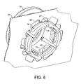
- FIG. 6 is a view of the completed moulding from the reverse side of the strip.
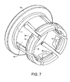
- FIG. 7 is a perspective view of the collet following detachment from the strip metal.
- FIG. 8 is a diagrammatic view of one form of injection moulding tool for forming a collet in accordance with the invention.
- the collet is shown indicated generally at 10 comprising an annular collar 11 having an out-turned flange 12 on one side and a plurality of resilient arms 13 extending from the other side generaly parallel to the collet axis which is indicated at 14 .
- heads 15 are formed on the arms the outer faces 15 a of which are shaped to cooperate with a tapered cam surface in the coupling body in which the collet is to be used to force the arms inwardly into engagement with a tube extending through the collet.
- the inner sides of the heads formed with a step 15 b in use, will face inwardly of the coupling body.
- the greater part of the collet including the collar, head, arms and part of the heads at the ends of the collet arms is formed from a relatively flexible plastic material such as nylon or polypropylene with or without a mineral filling.
- the material is selected to provide adequate strength for the collet but also flexibility in the arms 13 to allow the arms to be deflected inwardly into griping engagement with a tube by the tapered cam surface as mentioned earlier.
- the heads 15 of the collet at the ends of the collet arms are formed with inserts 16 moulded in a more rigid plastics material such as glass filled nylon or glass filled polyphenylene sulfide (PPS) to enable the heads to withstand higher loads in the plastics material used for the rest of the collar particularly at higher temperatures.
- a more rigid plastics material such as glass filled nylon or glass filled polyphenylene sulfide (PPS) to enable the heads to withstand higher loads in the plastics material used for the rest of the collar particularly at higher temperatures.
- each head comprises the insert 16 and a U-shaped portion 17 the ends of which are integral with the arms of the collet and which is formed in the same material as the rest of the collet.
- Each insert 16 has a raised rib 18 extending around the sides and bottom of the insert adjacent the U-shaped element 17 .
- the U-shaped element 17 is moulded onto the insert and, in so doing, envelopes the rib 18 so that the insert is positively keyed into the part 17 of the head.
- the outer surface of the head 15 has an inclined face 19 which engages with the tapered cam surface in the coupling body to force the arms of the collet inwardly into engagement with the tube passing through the collet with slight outward movement of the collet in the coupling body.
- the inner side of the insert is formed with a step 20 facing away from the collar 11 of the collet and a Z-shaped metal tooth 21 which is embedded in the insert 16 .
- the inner end 22 of the tooth is angled to project outwardly of the insert at the top of the step 20 and to provide an edge to engage and grip a tube in the collet.
- a strip 25 of stainless steel is used to provide the teeth 21 of the plastic inserts for the heads of the collet and also serves to carry the teeth through the moulding operation.
- Apertures 26 are punched in the strip with spaced curve recesses 27 to define a series of teeth 21 spaced around the aperture 26 at appropriate positions for the forming of the collet.
- Deep rectangular apertures 28 are also punched at the outer sides of the teeth leaving the teeth connected to the strip by narrow nibs of metal 29 which can readily be severed when the moulding operation is complete as described later.
- the punching operation is also used to appreciate teeth 21 to have the slight Z form cross-section which can be seen in FIG. 3 .
- the strip is then fed to a moulding machine where the inserts 16 are moulded onto the teeth in a glass filled nylon or glass filled PPS plastics material to provide a relatively rigid and strong body of material in which the teeth 21 are embedded to produce a strip as shown in FIG. 4 .
- the rib 18 encircling each tooth to key into the rest of the head can clearly be seen.
- the strip then moves in the mould to a moulding station where the rest of the collet is moulded to produce a complete collet as shown in FIGS. 5 and 6 .
- the nibs 29 attaching the strip to the teeth are then severed to leave the completed collet as shown in FIG. 7 .
- moulding steps may be carried out in the reverse order.
- moulding operation could be carried out in one operation first forming the inserts and then the complete collet using the same machine barrel/nozzle.
- the invention is also applicable to forming collets for use in the tube couplings described in our European Patent Specification Nos. 0691503, 0663557 and 0756125 (GSL and SL type collets).
- FIG. 8 of the drawings there is shown in diagrammatic form an injection moulding tool for producing a collet in accordance with the invention.
- the tool is indicated generally at 100 and comprises an annular cavity 101 designed to mould the collet head and having an inlet runner 102 connected to a screw extruder for feeding plastics material to the mould cavity.
- Elongate cavities 103 extend from the annular cavity at spaced positions around the cavity coaxially with the axis of cavity to form the collet arms and the distal ends of the elongate cavities have enlarged chambers 104 to form the heads at the ends of the arms.
- a high strength plastics material is initially fed by the extruder to fill the chambers 104 and thereby form high strength heads for the collet to the required shape.
- the high strength plastics material injected into the mould cavity is followed by a lower strength material which forms the arms and annular end of the collet.
- plastics materials may be different but compatible materials or may have the same base material with the high strengths are filled with reinforcing fibres and the low strengths material having no fibre content or a much lower fibre content.
Abstract
Description
Claims (20)
Applications Claiming Priority (4)
| Application Number | Priority Date | Filing Date | Title |
|---|---|---|---|
| GB0411785A GB0411785D0 (en) | 2004-05-26 | 2004-05-26 | Improvements in or relating to collets for tube couplings |
| GB0411785.9 | 2004-05-26 | ||
| GB0419962A GB0419962D0 (en) | 2004-09-08 | 2004-09-08 | Improvements in or relating to collets for tube couplings |
| GB0419962.6 | 2004-09-08 |
Publications (2)
| Publication Number | Publication Date |
|---|---|
| US20050264009A1 US20050264009A1 (en) | 2005-12-01 |
| US7422248B2 true US7422248B2 (en) | 2008-09-09 |
Family
ID=34981366
Family Applications (1)
| Application Number | Title | Priority Date | Filing Date |
|---|---|---|---|
| US11/116,638 Expired - Fee Related US7422248B2 (en) | 2004-05-26 | 2005-04-28 | Collets for tube couplings |
Country Status (8)
| Country | Link |
|---|---|
| US (1) | US7422248B2 (en) |
| EP (1) | EP1600682B1 (en) |
| JP (1) | JP2005337501A (en) |
| KR (1) | KR100905007B1 (en) |
| AT (1) | ATE516465T1 (en) |
| AU (1) | AU2005201888B2 (en) |
| NZ (1) | NZ539383A (en) |
| PL (1) | PL1600682T3 (en) |
Cited By (3)
| Publication number | Priority date | Publication date | Assignee | Title |
|---|---|---|---|---|
| US20100066075A1 (en) * | 2007-05-25 | 2010-03-18 | Crompton David B | Removal tool and method for push-fit fluid flow systems |
| US20130168959A1 (en) * | 2010-07-13 | 2013-07-04 | Cliquot Holdings (Pty) Ltd | Pipe fitting |
| US9630856B2 (en) | 2011-04-14 | 2017-04-25 | Grzegorz Loniewski | Water filter faucet and cartridge therefor |
Families Citing this family (8)
| Publication number | Priority date | Publication date | Assignee | Title |
|---|---|---|---|---|
| CN101761719B (en) * | 2009-08-11 | 2013-06-19 | 叶炎彬 | Rapid pipeline connector |
| GB201317952D0 (en) | 2013-10-10 | 2013-11-27 | Guest John Int Ltd | A connector for connecting to a tube |
| GB201317990D0 (en) | 2013-10-11 | 2013-11-27 | Guest John Int Ltd | A conncetor |
| CN105736879A (en) * | 2016-04-20 | 2016-07-06 | 金凌 | Anchor-point clamping jaw |
| GB2575620A (en) | 2018-04-27 | 2020-01-22 | John Guest International Ltd | A collet for locking a tube in a coupling body |
| AT520743B1 (en) * | 2018-05-16 | 2019-07-15 | E Hawle Armaturenwerke Gmbh | clamping ring |
| FR3102227B1 (en) * | 2019-10-17 | 2021-10-01 | Akwel | Fluid connection device, in particular for the ventilation of a gearbox housing |
| USD985103S1 (en) * | 2022-11-25 | 2023-05-02 | Guangzhou Mibo Zhilian Technology Co. Ltd | Fixed sleeve for rod |
Citations (72)
| Publication number | Priority date | Publication date | Assignee | Title |
|---|---|---|---|---|
| US2452277A (en) | 1945-05-10 | 1948-10-26 | George V Woodling | Tube coupling |
| US2475741A (en) | 1943-01-06 | 1949-07-12 | Robert A Goeller | Connector |
| US2640716A (en) | 1948-12-28 | 1953-06-02 | Arthur L Bigelow | Tube coupling |
| US2728895A (en) | 1954-10-04 | 1955-12-27 | Whitney Blake Co | Self-locking coupling device |
| US2953398A (en) | 1956-05-28 | 1960-09-20 | United States Pipe Foundry | Pipe joint |
| US3107108A (en) | 1957-11-26 | 1963-10-15 | Whitney E Greene | Tube coupling |
| US3180664A (en) | 1961-07-20 | 1965-04-27 | Imp Eastman Corp | Ball pipe joint with composite ball member |
| US3233924A (en) | 1963-04-18 | 1966-02-08 | Parker Hannifin Corp | High pressure coupling |
| GB1024537A (en) | 1963-10-30 | 1966-03-30 | Neue Argus Gmbh | Push-in pipeline coupling with displaceable unlocking ring |
| US3250550A (en) | 1964-02-13 | 1966-05-10 | Gilbert T Lyon | Self-flaring tube coupling |
| US3334661A (en) | 1964-01-03 | 1967-08-08 | Kenneth A Milette | Pipe union |
| US3380765A (en) | 1963-11-26 | 1968-04-30 | Dilo Ges Drexler & Co | Pipe union |
| US3454290A (en) | 1966-11-21 | 1969-07-08 | Carpano & Pons | Adapter for flexible tubing |
| US3552781A (en) | 1968-05-28 | 1971-01-05 | Raufoss Ammunisjonsfabrikker | Pipe or hose coupling |
| US3679241A (en) | 1969-06-11 | 1972-07-25 | Schmidt & Co Gmbh Kranz | Compression pipe coupling |
| US3747964A (en) | 1971-12-15 | 1973-07-24 | N Nilsen | Quick coupling and seal |
| US3834742A (en) | 1971-02-05 | 1974-09-10 | Parker Hannifin Corp | Tube coupling |
| FR2227483A1 (en) | 1973-04-24 | 1974-11-22 | Legris France Sa | |
| US3989283A (en) | 1975-07-23 | 1976-11-02 | Genova, Inc. | Compression fitting |
| US4005883A (en) | 1974-08-05 | 1977-02-01 | Guest John D | Tube couplings |
| US4025093A (en) | 1975-07-04 | 1977-05-24 | Plasson Maagan Michael Industries Limited | Pipe couplings and split rings used therein |
| US4062572A (en) | 1976-08-30 | 1977-12-13 | Inner-Tite, A Division Of Yara Engineering Corporation | Transition fittings |
| FR2394736A1 (en) | 1977-06-16 | 1979-01-12 | Cetri Sa | Tube coupling for fluid circuit - has shearable body with wedge surface which deforms lip to engage in tube surface |
| US4136897A (en) | 1976-04-08 | 1979-01-30 | Parker-Hannifin Corporation | Coupling device for tubular members |
| US4188051A (en) | 1977-04-22 | 1980-02-12 | Parker-Hannifin Corporation | Tube coupling |
| GB1573757A (en) | 1977-02-09 | 1980-08-28 | Guest J D | Couplings for tubes |
| US4253686A (en) | 1979-04-10 | 1981-03-03 | Aitken W Sidney | Pipe coupling useful at high fluid pressures |
| US4298222A (en) | 1980-07-23 | 1981-11-03 | Jaco Manufacturing Company | Tube coupling |
| US4305606A (en) | 1978-11-24 | 1981-12-15 | Societe Legris France S.A. | Quick-releasable connectors for flexible plastic pipes |
| US4309050A (en) | 1979-07-06 | 1982-01-05 | Societe Anonyme Dite: Legris | Pipe fittings, and in particular for high pressure fluid pipes |
| US4335908A (en) | 1980-05-19 | 1982-06-22 | Burge Donald G | Push-in tube connector |
| US4588214A (en) * | 1982-12-13 | 1986-05-13 | John Guest Limited | Couplings for tubes and other fluid handling components |
| GB2167147A (en) | 1984-11-12 | 1986-05-21 | Guest John D | Tube couplings |
| US4606783A (en) * | 1982-12-13 | 1986-08-19 | Guest John D | Tube couplings |
| US4613158A (en) | 1982-08-27 | 1986-09-23 | Ekman K R | Arrangement for a coupling with a first and a second coupling part and a method for production of the coupling |
| US4645246A (en) * | 1985-03-28 | 1987-02-24 | Guest John D | Tube couplers |
| US4655159A (en) | 1985-09-27 | 1987-04-07 | Raychem Corp. | Compression pressure indicator |
| US4867489A (en) | 1987-09-21 | 1989-09-19 | Parker Hannifin Corporation | Tube fitting |
| US4993755A (en) | 1989-09-22 | 1991-02-19 | Master Industries, Inc. | Quick connect fitting |
| US5056829A (en) | 1987-05-11 | 1991-10-15 | Prazisions-Werkzeug Ag | Device for interchangeable connection |
| US5121949A (en) | 1988-05-12 | 1992-06-16 | Dresser Industries, Inc. | Compression coupling |
| US5150924A (en) | 1987-09-29 | 1992-09-29 | Bridgestone Flowtech Corporation | Hose fitting |
| US5181751A (en) | 1990-05-31 | 1993-01-26 | Tokai Rubber Industries, Ltd. | Quick connector |
| US5217261A (en) | 1990-04-23 | 1993-06-08 | Aeroquip Corporation | Flareless compression fitting |
| FR2689205A1 (en) | 1992-03-30 | 1993-10-01 | Hutchinson | Connector adaptor for gas appliances - includes hollow body with cylindrical sealing joint mounted in it with set of anchoring claws designed to make contact and grip connector |
| US5362110A (en) | 1991-02-25 | 1994-11-08 | Moeller Manufacturing Co., Inc. | Fluid coupling and fastener capture device |
| US5370423A (en) * | 1992-02-28 | 1994-12-06 | Guest; John D. | Tube couplings |
| US5388866A (en) | 1990-03-09 | 1995-02-14 | Lourdes Industries | High pressure coupling with provision for preventing separation of parts and with anti-galling provision |
| US5390969A (en) * | 1992-09-09 | 1995-02-21 | Guest; John D. | Collets for tube couplings |
| US5443289A (en) * | 1992-11-11 | 1995-08-22 | Guest; John D. | Tube couplings |
| WO1995028593A1 (en) | 1994-04-19 | 1995-10-26 | David Frederick Hawkins | Improvements in tube connectors |
| US5466019A (en) | 1994-09-26 | 1995-11-14 | Komolrochanaporn; Naris | Pipe coupling |
| US5569713A (en) * | 1993-08-09 | 1996-10-29 | American Commodities, Inc. | Blend composition containing recycled polycarbonate and recycled polymethylmethacrylate |
| US5584513A (en) * | 1992-03-06 | 1996-12-17 | Parker-Hannifin Corporation | Push in plastic tube fitting |
| US5593186A (en) | 1993-07-20 | 1997-01-14 | Philmac Pty Ltd | Coupling for outer surface engagement of polymeric pipe |
| US5607190A (en) | 1994-03-04 | 1997-03-04 | Hutchinson | Quick and leaktight joining device for tubular pipes |
| EP0663557B1 (en) | 1994-01-13 | 1997-03-05 | John Derek Guest | Improvements in or relating to tube couplings |
| US5957509A (en) | 1998-10-16 | 1999-09-28 | Komolrochanaporn; Naris | Pipe coupling |
| EP0945662A2 (en) | 1998-03-27 | 1999-09-29 | John Derek Guest | Improvements in or relating to tube couplings |
| US6095572A (en) | 1998-01-20 | 2000-08-01 | Optimize Technologies, Inc. | Quarter turn quick connect fitting |
| US6109664A (en) * | 1997-06-12 | 2000-08-29 | Guest; John Derek | Collets for locking tubes in coupling bodies |
| US6193239B1 (en) | 1997-04-14 | 2001-02-27 | Smc Kabushiki Kaisha | Tube joint |
| EP1087168A1 (en) | 1999-09-27 | 2001-03-28 | Legris S.A. | A device for connecting a pipe to a conduit member |
| US6293595B1 (en) | 1993-09-29 | 2001-09-25 | Jpb Systeme | Anti-rotation locking units, and apparatus equipped therewith |
| EP0756125B1 (en) | 1995-07-28 | 2002-05-22 | John Guest Limited | Tube coupling |
| US20020109353A1 (en) | 2001-02-15 | 2002-08-15 | John Guest International Limited | Tube couplings |
| US20020135184A1 (en) | 2001-01-19 | 2002-09-26 | Snyder Ronald R. | Mechanical pipe coupling derived from a standard fitting |
| US20030006610A1 (en) | 2001-07-09 | 2003-01-09 | Werth Albert A. | Barb clamp |
| US20030085568A1 (en) | 2001-11-07 | 2003-05-08 | John Guest International Ltd. | Tube couplings |
| EP1359363A2 (en) | 2002-04-30 | 2003-11-05 | John Guest International Limited | Tube coupling |
| EP1359362A1 (en) | 2002-04-30 | 2003-11-05 | John Guest International Limited | Improvements in or relating to tube couplings |
| US20040032125A1 (en) | 2002-04-23 | 2004-02-19 | Rehder Randall J. | Connector |
Family Cites Families (4)
| Publication number | Priority date | Publication date | Assignee | Title |
|---|---|---|---|---|
| DE2226151C2 (en) * | 1972-05-29 | 1974-06-27 | Georg 8000 Muenchen Seiler | Push-in socket connection of pipes or pipe elements, in particular made of metal |
| GB2091830A (en) * | 1981-01-23 | 1982-08-04 | Vfp Corp | Plastics tube fitting |
| ES2015301B3 (en) * | 1986-07-30 | 1990-08-16 | Guest John D | TUBE COUPLINGS. |
| EP0334648B1 (en) * | 1988-03-25 | 1993-08-11 | John Derek Guest | Improvements in or relating to methods of manufacturing tube coupling bodies |
-
2005
- 2005-04-12 NZ NZ539383A patent/NZ539383A/en not_active IP Right Cessation
- 2005-04-15 PL PL05252376T patent/PL1600682T3/en unknown
- 2005-04-15 EP EP05252376A patent/EP1600682B1/en not_active Not-in-force
- 2005-04-15 AT AT05252376T patent/ATE516465T1/en not_active IP Right Cessation
- 2005-04-28 US US11/116,638 patent/US7422248B2/en not_active Expired - Fee Related
- 2005-05-04 AU AU2005201888A patent/AU2005201888B2/en not_active Ceased
- 2005-05-25 JP JP2005152563A patent/JP2005337501A/en active Pending
- 2005-05-25 KR KR1020050044129A patent/KR100905007B1/en active IP Right Grant
Patent Citations (79)
| Publication number | Priority date | Publication date | Assignee | Title |
|---|---|---|---|---|
| US2475741A (en) | 1943-01-06 | 1949-07-12 | Robert A Goeller | Connector |
| US2452277A (en) | 1945-05-10 | 1948-10-26 | George V Woodling | Tube coupling |
| US2640716A (en) | 1948-12-28 | 1953-06-02 | Arthur L Bigelow | Tube coupling |
| US2728895A (en) | 1954-10-04 | 1955-12-27 | Whitney Blake Co | Self-locking coupling device |
| US2953398A (en) | 1956-05-28 | 1960-09-20 | United States Pipe Foundry | Pipe joint |
| US3107108A (en) | 1957-11-26 | 1963-10-15 | Whitney E Greene | Tube coupling |
| US3180664A (en) | 1961-07-20 | 1965-04-27 | Imp Eastman Corp | Ball pipe joint with composite ball member |
| US3233924A (en) | 1963-04-18 | 1966-02-08 | Parker Hannifin Corp | High pressure coupling |
| GB1024537A (en) | 1963-10-30 | 1966-03-30 | Neue Argus Gmbh | Push-in pipeline coupling with displaceable unlocking ring |
| US3380765A (en) | 1963-11-26 | 1968-04-30 | Dilo Ges Drexler & Co | Pipe union |
| US3334661A (en) | 1964-01-03 | 1967-08-08 | Kenneth A Milette | Pipe union |
| US3250550A (en) | 1964-02-13 | 1966-05-10 | Gilbert T Lyon | Self-flaring tube coupling |
| US3454290A (en) | 1966-11-21 | 1969-07-08 | Carpano & Pons | Adapter for flexible tubing |
| US3552781A (en) | 1968-05-28 | 1971-01-05 | Raufoss Ammunisjonsfabrikker | Pipe or hose coupling |
| US3679241A (en) | 1969-06-11 | 1972-07-25 | Schmidt & Co Gmbh Kranz | Compression pipe coupling |
| US3834742A (en) | 1971-02-05 | 1974-09-10 | Parker Hannifin Corp | Tube coupling |
| US3747964A (en) | 1971-12-15 | 1973-07-24 | N Nilsen | Quick coupling and seal |
| US3909046A (en) | 1973-04-24 | 1975-09-30 | Legris France Sa | Connector for fluid conduits, such as semi-rigid pipes |
| FR2227483A1 (en) | 1973-04-24 | 1974-11-22 | Legris France Sa | |
| US4005883A (en) | 1974-08-05 | 1977-02-01 | Guest John D | Tube couplings |
| US4025093A (en) | 1975-07-04 | 1977-05-24 | Plasson Maagan Michael Industries Limited | Pipe couplings and split rings used therein |
| US3989283A (en) | 1975-07-23 | 1976-11-02 | Genova, Inc. | Compression fitting |
| GB1520742A (en) | 1975-07-30 | 1978-08-09 | Guest J D | Couplings for tubes |
| US4136897A (en) | 1976-04-08 | 1979-01-30 | Parker-Hannifin Corporation | Coupling device for tubular members |
| US4062572A (en) | 1976-08-30 | 1977-12-13 | Inner-Tite, A Division Of Yara Engineering Corporation | Transition fittings |
| GB1573757A (en) | 1977-02-09 | 1980-08-28 | Guest J D | Couplings for tubes |
| US4188051A (en) | 1977-04-22 | 1980-02-12 | Parker-Hannifin Corporation | Tube coupling |
| FR2394736A1 (en) | 1977-06-16 | 1979-01-12 | Cetri Sa | Tube coupling for fluid circuit - has shearable body with wedge surface which deforms lip to engage in tube surface |
| US4305606A (en) | 1978-11-24 | 1981-12-15 | Societe Legris France S.A. | Quick-releasable connectors for flexible plastic pipes |
| US4253686A (en) | 1979-04-10 | 1981-03-03 | Aitken W Sidney | Pipe coupling useful at high fluid pressures |
| US4309050A (en) | 1979-07-06 | 1982-01-05 | Societe Anonyme Dite: Legris | Pipe fittings, and in particular for high pressure fluid pipes |
| US4335908A (en) | 1980-05-19 | 1982-06-22 | Burge Donald G | Push-in tube connector |
| US4298222A (en) | 1980-07-23 | 1981-11-03 | Jaco Manufacturing Company | Tube coupling |
| US4613158A (en) | 1982-08-27 | 1986-09-23 | Ekman K R | Arrangement for a coupling with a first and a second coupling part and a method for production of the coupling |
| US4588214A (en) * | 1982-12-13 | 1986-05-13 | John Guest Limited | Couplings for tubes and other fluid handling components |
| US4606783A (en) * | 1982-12-13 | 1986-08-19 | Guest John D | Tube couplings |
| GB2167147A (en) | 1984-11-12 | 1986-05-21 | Guest John D | Tube couplings |
| US4637636A (en) | 1984-11-12 | 1987-01-20 | Guest John D | Tube couplings |
| US4645246A (en) * | 1985-03-28 | 1987-02-24 | Guest John D | Tube couplers |
| US4655159A (en) | 1985-09-27 | 1987-04-07 | Raychem Corp. | Compression pressure indicator |
| US5056829A (en) | 1987-05-11 | 1991-10-15 | Prazisions-Werkzeug Ag | Device for interchangeable connection |
| US4867489A (en) | 1987-09-21 | 1989-09-19 | Parker Hannifin Corporation | Tube fitting |
| US5150924A (en) | 1987-09-29 | 1992-09-29 | Bridgestone Flowtech Corporation | Hose fitting |
| US5121949A (en) | 1988-05-12 | 1992-06-16 | Dresser Industries, Inc. | Compression coupling |
| US4993755A (en) | 1989-09-22 | 1991-02-19 | Master Industries, Inc. | Quick connect fitting |
| US5388866A (en) | 1990-03-09 | 1995-02-14 | Lourdes Industries | High pressure coupling with provision for preventing separation of parts and with anti-galling provision |
| US5217261A (en) | 1990-04-23 | 1993-06-08 | Aeroquip Corporation | Flareless compression fitting |
| US5181751A (en) | 1990-05-31 | 1993-01-26 | Tokai Rubber Industries, Ltd. | Quick connector |
| US5362110A (en) | 1991-02-25 | 1994-11-08 | Moeller Manufacturing Co., Inc. | Fluid coupling and fastener capture device |
| US5370423A (en) * | 1992-02-28 | 1994-12-06 | Guest; John D. | Tube couplings |
| US5584513A (en) * | 1992-03-06 | 1996-12-17 | Parker-Hannifin Corporation | Push in plastic tube fitting |
| FR2689205A1 (en) | 1992-03-30 | 1993-10-01 | Hutchinson | Connector adaptor for gas appliances - includes hollow body with cylindrical sealing joint mounted in it with set of anchoring claws designed to make contact and grip connector |
| US5390969A (en) * | 1992-09-09 | 1995-02-21 | Guest; John D. | Collets for tube couplings |
| US5443289A (en) * | 1992-11-11 | 1995-08-22 | Guest; John D. | Tube couplings |
| EP0691503A2 (en) | 1992-11-11 | 1996-01-10 | John Derek Guest | Tube couplings |
| US5593186A (en) | 1993-07-20 | 1997-01-14 | Philmac Pty Ltd | Coupling for outer surface engagement of polymeric pipe |
| US5569713A (en) * | 1993-08-09 | 1996-10-29 | American Commodities, Inc. | Blend composition containing recycled polycarbonate and recycled polymethylmethacrylate |
| US6293595B1 (en) | 1993-09-29 | 2001-09-25 | Jpb Systeme | Anti-rotation locking units, and apparatus equipped therewith |
| EP0663557B1 (en) | 1994-01-13 | 1997-03-05 | John Derek Guest | Improvements in or relating to tube couplings |
| US5607190A (en) | 1994-03-04 | 1997-03-04 | Hutchinson | Quick and leaktight joining device for tubular pipes |
| WO1995028593A1 (en) | 1994-04-19 | 1995-10-26 | David Frederick Hawkins | Improvements in tube connectors |
| US5466019A (en) | 1994-09-26 | 1995-11-14 | Komolrochanaporn; Naris | Pipe coupling |
| EP0756125B1 (en) | 1995-07-28 | 2002-05-22 | John Guest Limited | Tube coupling |
| US6193239B1 (en) | 1997-04-14 | 2001-02-27 | Smc Kabushiki Kaisha | Tube joint |
| US6109664A (en) * | 1997-06-12 | 2000-08-29 | Guest; John Derek | Collets for locking tubes in coupling bodies |
| US6095572A (en) | 1998-01-20 | 2000-08-01 | Optimize Technologies, Inc. | Quarter turn quick connect fitting |
| US6056326A (en) | 1998-03-27 | 2000-05-02 | Guest; John Derek | Tube couplings |
| EP0945662A2 (en) | 1998-03-27 | 1999-09-29 | John Derek Guest | Improvements in or relating to tube couplings |
| US5957509A (en) | 1998-10-16 | 1999-09-28 | Komolrochanaporn; Naris | Pipe coupling |
| EP1087168A1 (en) | 1999-09-27 | 2001-03-28 | Legris S.A. | A device for connecting a pipe to a conduit member |
| US20020135184A1 (en) | 2001-01-19 | 2002-09-26 | Snyder Ronald R. | Mechanical pipe coupling derived from a standard fitting |
| EP1233225A1 (en) | 2001-02-15 | 2002-08-21 | John Guest International Limited | Improvements in or relating to tube couplings |
| US20020109353A1 (en) | 2001-02-15 | 2002-08-15 | John Guest International Limited | Tube couplings |
| US20030006610A1 (en) | 2001-07-09 | 2003-01-09 | Werth Albert A. | Barb clamp |
| US20030085568A1 (en) | 2001-11-07 | 2003-05-08 | John Guest International Ltd. | Tube couplings |
| EP1310720A2 (en) | 2001-11-07 | 2003-05-14 | John Guest International Limited | Improvements in or relating to tube couplings |
| US20040032125A1 (en) | 2002-04-23 | 2004-02-19 | Rehder Randall J. | Connector |
| EP1359363A2 (en) | 2002-04-30 | 2003-11-05 | John Guest International Limited | Tube coupling |
| EP1359362A1 (en) | 2002-04-30 | 2003-11-05 | John Guest International Limited | Improvements in or relating to tube couplings |
Cited By (4)
| Publication number | Priority date | Publication date | Assignee | Title |
|---|---|---|---|---|
| US20100066075A1 (en) * | 2007-05-25 | 2010-03-18 | Crompton David B | Removal tool and method for push-fit fluid flow systems |
| US20130168959A1 (en) * | 2010-07-13 | 2013-07-04 | Cliquot Holdings (Pty) Ltd | Pipe fitting |
| US8870235B2 (en) * | 2010-07-13 | 2014-10-28 | Cliquot Holdings (Pty) Ltd. | Pipe fitting |
| US9630856B2 (en) | 2011-04-14 | 2017-04-25 | Grzegorz Loniewski | Water filter faucet and cartridge therefor |
Also Published As
| Publication number | Publication date |
|---|---|
| AU2005201888B2 (en) | 2010-07-01 |
| PL1600682T3 (en) | 2011-12-30 |
| KR20060049453A (en) | 2006-05-19 |
| EP1600682A2 (en) | 2005-11-30 |
| EP1600682B1 (en) | 2011-07-13 |
| JP2005337501A (en) | 2005-12-08 |
| NZ539383A (en) | 2006-11-30 |
| EP1600682A3 (en) | 2005-12-07 |
| US20050264009A1 (en) | 2005-12-01 |
| KR100905007B1 (en) | 2009-06-26 |
| AU2005201888A1 (en) | 2005-12-15 |
| ATE516465T1 (en) | 2011-07-15 |
Similar Documents
| Publication | Publication Date | Title |
|---|---|---|
| US7422248B2 (en) | Collets for tube couplings | |
| EP0334648A2 (en) | Improvements in or relating to methods of manufacturing tube coupling bodies | |
| US5529743A (en) | Methods for the manufacture of clean air ducts | |
| US6695414B2 (en) | Method of manufacturing a brush head by way of an injection molding process | |
| EP1864588B1 (en) | Tooth brush and method for its production | |
| US4919373A (en) | Push mount tie | |
| US6863855B2 (en) | Method of making a cable tie using insert molding | |
| JP2005337501A5 (en) | ||
| KR20110130425A (en) | Cable tie | |
| JP6932721B2 (en) | High-performance two-material cable tie head | |
| CN101046031B (en) | Method for manufacturing plastic coiling tool bar and plastic coiling tool bar | |
| ATE121002T1 (en) | PLASTIC MOLDED COMPONENT AND METHOD FOR PRODUCING IT. | |
| CN101727779A (en) | Attachment member and method of manufacturing the same | |
| EP0936046A1 (en) | Method and apparatus for manufacturing a gasket sealing for a plastic fitting or fitting ring | |
| JP2020124849A (en) | Molding method for plastic products | |
| EP0253576B1 (en) | Conduit couplings | |
| US6321434B1 (en) | Method for manufacturing sealing tool | |
| CN111867938B (en) | Self-locking cable tie with elastomeric features and method of making same | |
| US6171539B1 (en) | Method for forming a molded grommet | |
| EP0972624B1 (en) | Method and molding device for forming a grommet | |
| CN213602322U (en) | Fixing structure | |
| US6877907B2 (en) | Arrangement of several ferrules for optical waveguides and process of manufacturing a belt of plastic ferrules | |
| CN219407676U (en) | Ribbon | |
| ES2367026T3 (en) | IMPROVEMENTS IN CIRCULAR METAL PLATES FOR PIPE COUPLINGS. | |
| JP3052501U (en) | Male fastener and its mold structure |
Legal Events
| Date | Code | Title | Description |
|---|---|---|---|
| AS | Assignment |
Owner name: JOHN GUEST INTERNATIONAL LIMITED, UNITED KINGDOM Free format text: ASSIGNMENT OF ASSIGNORS INTEREST;ASSIGNOR:GUEST, TIMOTHY STEPHEN;REEL/FRAME:016519/0671 Effective date: 20050218 |
|
| STCF | Information on status: patent grant |
Free format text: PATENTED CASE |
|
| CC | Certificate of correction | ||
| FPAY | Fee payment |
Year of fee payment: 4 |
|
| FPAY | Fee payment |
Year of fee payment: 8 |
|
| FEPP | Fee payment procedure |
Free format text: MAINTENANCE FEE REMINDER MAILED (ORIGINAL EVENT CODE: REM.); ENTITY STATUS OF PATENT OWNER: LARGE ENTITY |
|
| LAPS | Lapse for failure to pay maintenance fees |
Free format text: PATENT EXPIRED FOR FAILURE TO PAY MAINTENANCE FEES (ORIGINAL EVENT CODE: EXP.); ENTITY STATUS OF PATENT OWNER: LARGE ENTITY |
|
| STCH | Information on status: patent discontinuation |
Free format text: PATENT EXPIRED DUE TO NONPAYMENT OF MAINTENANCE FEES UNDER 37 CFR 1.362 |
|
| FP | Lapsed due to failure to pay maintenance fee |
Effective date: 20200909 |