US7428774B2 - Baffle for an automotive vehicle and method of use therefor - Google Patents
Baffle for an automotive vehicle and method of use therefor Download PDFInfo
- Publication number
- US7428774B2 US7428774B2 US11/136,742 US13674205A US7428774B2 US 7428774 B2 US7428774 B2 US 7428774B2 US 13674205 A US13674205 A US 13674205A US 7428774 B2 US7428774 B2 US 7428774B2
- Authority
- US
- United States
- Prior art keywords
- baffle
- expandable material
- opening
- bolt
- seal
- Prior art date
- Legal status (The legal status is an assumption and is not a legal conclusion. Google has not performed a legal analysis and makes no representation as to the accuracy of the status listed.)
- Active, expires
Links
Images


Classifications
-
- B—PERFORMING OPERATIONS; TRANSPORTING
- B62—LAND VEHICLES FOR TRAVELLING OTHERWISE THAN ON RAILS
- B62D—MOTOR VEHICLES; TRAILERS
- B62D29/00—Superstructures, understructures, or sub-units thereof, characterised by the material thereof
- B62D29/001—Superstructures, understructures, or sub-units thereof, characterised by the material thereof characterised by combining metal and synthetic material
- B62D29/002—Superstructures, understructures, or sub-units thereof, characterised by the material thereof characterised by combining metal and synthetic material a foamable synthetic material or metal being added in situ
-
- B—PERFORMING OPERATIONS; TRANSPORTING
- B60—VEHICLES IN GENERAL
- B60R—VEHICLES, VEHICLE FITTINGS, OR VEHICLE PARTS, NOT OTHERWISE PROVIDED FOR
- B60R13/00—Elements for body-finishing, identifying, or decorating; Arrangements or adaptations for advertising purposes
- B60R13/08—Insulating elements, e.g. for sound insulation
- B60R13/0815—Acoustic or thermal insulation of passenger compartments
-
- B—PERFORMING OPERATIONS; TRANSPORTING
- B60—VEHICLES IN GENERAL
- B60R—VEHICLES, VEHICLE FITTINGS, OR VEHICLE PARTS, NOT OTHERWISE PROVIDED FOR
- B60R13/00—Elements for body-finishing, identifying, or decorating; Arrangements or adaptations for advertising purposes
- B60R13/08—Insulating elements, e.g. for sound insulation
- B60R2013/0807—Arrangements of fasteners or clips specially adapted therefore
-
- B—PERFORMING OPERATIONS; TRANSPORTING
- B62—LAND VEHICLES FOR TRAVELLING OTHERWISE THAN ON RAILS
- B62D—MOTOR VEHICLES; TRAILERS
- B62D25/00—Superstructure or monocoque structure sub-units; Parts or details thereof not otherwise provided for
-
- Y—GENERAL TAGGING OF NEW TECHNOLOGICAL DEVELOPMENTS; GENERAL TAGGING OF CROSS-SECTIONAL TECHNOLOGIES SPANNING OVER SEVERAL SECTIONS OF THE IPC; TECHNICAL SUBJECTS COVERED BY FORMER USPC CROSS-REFERENCE ART COLLECTIONS [XRACs] AND DIGESTS
- Y10—TECHNICAL SUBJECTS COVERED BY FORMER USPC
- Y10T—TECHNICAL SUBJECTS COVERED BY FORMER US CLASSIFICATION
- Y10T29/00—Metal working
- Y10T29/49—Method of mechanical manufacture
- Y10T29/49616—Structural member making
- Y10T29/49618—Restoring existing member, e.g., reinforcing, repairing
-
- Y—GENERAL TAGGING OF NEW TECHNOLOGICAL DEVELOPMENTS; GENERAL TAGGING OF CROSS-SECTIONAL TECHNOLOGIES SPANNING OVER SEVERAL SECTIONS OF THE IPC; TECHNICAL SUBJECTS COVERED BY FORMER USPC CROSS-REFERENCE ART COLLECTIONS [XRACs] AND DIGESTS
- Y10—TECHNICAL SUBJECTS COVERED BY FORMER USPC
- Y10T—TECHNICAL SUBJECTS COVERED BY FORMER US CLASSIFICATION
- Y10T29/00—Metal working
- Y10T29/49—Method of mechanical manufacture
- Y10T29/49616—Structural member making
- Y10T29/49622—Vehicular structural member making
-
- Y—GENERAL TAGGING OF NEW TECHNOLOGICAL DEVELOPMENTS; GENERAL TAGGING OF CROSS-SECTIONAL TECHNOLOGIES SPANNING OVER SEVERAL SECTIONS OF THE IPC; TECHNICAL SUBJECTS COVERED BY FORMER USPC CROSS-REFERENCE ART COLLECTIONS [XRACs] AND DIGESTS
- Y10—TECHNICAL SUBJECTS COVERED BY FORMER USPC
- Y10T—TECHNICAL SUBJECTS COVERED BY FORMER US CLASSIFICATION
- Y10T29/00—Metal working
- Y10T29/49—Method of mechanical manufacture
- Y10T29/49826—Assembling or joining
- Y10T29/49947—Assembling or joining by applying separate fastener
- Y10T29/49966—Assembling or joining by applying separate fastener with supplemental joining
Definitions
- the present invention relates generally to an insert or baffle for an automotive vehicle and more particularly to a baffle designed to accommodate one or more components of the automotive vehicle.
- New vehicle designs can create cavities that are difficult for baffles to seal because of the shape, location, size or the like of the cavities. Additionally, such cavities can be difficult to access, which, in turn, can cause difficulties for assembling baffles to the vehicles. New vehicle designs can also cause vehicle components such as fasteners or other components to be positioned in different locations within a vehicle and, as a consequence, baffles may have to be designed to accommodate such components while still being able to effectively seal or baffle components or cavities for minimizing sound transmission.
- baffles can be particularly difficult to design baffles to seal cavities between a forward body panel (e.g., a front quarter or fender panel) and an A-pillar of an automotive vehicle (e.g., a pick-up truck), particularly when the body panel is connected to the A-pillar with one or more fasteners.
- a forward body panel e.g., a front quarter or fender panel
- an A-pillar of an automotive vehicle e.g., a pick-up truck
- the present invention provides a baffle for addressing one or more of the difficulties discussed above.
- a baffle having one or more carrier layers and a layer of expandable material that is preferably substantially coextensive with the one or more carrier layers.
- the baffle has opening for receiving one or more fasteners designed to assist in desirably locating the baffle in a cavity of a structure of an automotive vehicle.
- the baffle also typically includes an additional opening (e.g., a through-hole) for accommodating a component of the automotive vehicle.
- the opening is suitable for allowing a bolt to be extended through the opening.
- FIG. 1 is a perspective view of an exemplary baffle in accordance with an aspect of the present invention.
- FIG. 2 is a front view of the exemplary baffle of FIG. 1 .
- FIG. 3 is a rear view of the exemplary baffle of FIG. 1
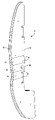
- FIG. 4 is a side view of the exemplary baffle of FIG. 1 .
- FIG. 5 is a rear view of a portion of an automotive vehicle prior to assembly of the exemplary baffle of FIGS. 1-4 .
- FIG. 6 is a rear view of the portion of the automotive vehicle after assembly of the exemplary baffle of FIGS. 1-4 .
- FIG. 7 is a close up view of a portion of an automotive vehicle prior to assembly of the exemplary baffle of FIGS. 1-4 .
- FIG. 8 is a close up view of the portion of the automotive vehicle after assembly of the exemplary baffle of FIGS. 1-4 .
- the present invention is predicated upon providing an improved system for sealing and baffling a cavity of an automotive vehicle.
- the baffle typically includes one or more of the following:
- the baffle 10 includes a first carrier layer 12 , a second carrier layer 14 and a layer 16 of expandable material.
- the first carrier layer 12 opposes the second carrier layer 14 and is substantially coextensive therewith.
- Each of the carrier layers 12 , 14 include a plurality of bend locations 18 .
- bend locations include actual bends of the carrier layer or deformations (e.g., scores, grooves, indents, markings, combination thereof or the like) which indicate locations that are bent when the baffle 10 is installed in an automotive vehicle.
- each of the carrier layers 12 , 14 include four bend locations 18 and the four bend locations 18 of the first carrier layer 12 are opposite the four bend locations 18 of the second carrier layer 14 .
- the first carrier layer 12 may be made of the same material or a different material than the second carrier layer 14 .
- the layers 12 , 14 are made of flexible materials such as fabrics, fibrous materials, plastic films or the like.
- both of the carrier layers 12 , 14 are formed of flexible metal foil.
- the carrier layers could be formed of more rigid materials such as molded or otherwise formed thermoplastics (e.g., polyamide), metal stampings, molded thermosets, composites, metal foam or the like.
- the layer 16 of expandable material is sandwiched between the first carrier layer 12 and the second carrier layer 14 for forming the baffle 10 .
- the layer 16 of expandable material is substantially coextensive with the first carrier layer 12 and the second carrier layer 14 .
- the first carrier layer 12 , the second carrier layer 14 and the layer 16 of expandable material and therefore, the baffle 10 each include a length (L) with a tapered upper end and a tapered lower end.
- the plurality of bend locations 18 are bent or can be bent to define an upper panel portion 30 , a lower panel portion 32 , and a central panel portion 34 in the baffle 10 .
- the baffle 10 also typically includes at least one opening (e.g., a cavity, a through-hole or the like) for accommodating a component (e.g., a fastener or other elongated member) of an automotive vehicle.
- a through-hole 38 extends through the carrier layers 12 , 14 and the layer 16 of expandable material. In the embodiment shown, the through-hole 38 extends through the central panel portion 34 of the baffle 10 .
- a plurality of fasteners 40 extend through the baffle 10 .
- each of the plurality of fasteners 40 is a plastic push pin that extends through the first carrier layer 12 , the layer 16 of expandable material and the second carrier layer 14 .
- two of the plurality of fasteners 40 extend through a lower portion 44 of the baffle 10 .
- One of the fasteners 40 extends through the baffle 10 adjacent the upper panel portion 30 .
- one of the fasteners 40 extends through an upper portion 46 of the baffle 10 .
- the expandable material is a heat activated material having foamable characteristics.
- the material may be generally dry to the touch or tacky and can be located upon or between one or more carrier layers in any form of desired pattern, placement, or thickness, but typically has a substantially uniform thickness.
- Exemplary expandable materials include L-5248, L-7002 and L-5204 foams available through L&L Products, Inc. of Romeo, Mich.
- a preferred heat activated material is an expandable plastic, and preferably one that is foamable.
- Particularly preferred materials are an epoxy-based and EVA (Ethylene Vinyl Acetate) based structural, sealing, baffling or sound-absorbing foams.
- the structural foam may be an epoxy-based material, including an ethylene copolymer or terpolymer that may possess an alpha-olefin.
- the polymer is composed of two or three different monomers, i.e., small molecules with high chemical reactivity that are capable of linking up with similar molecules.
- a number of reinforcing, sealing and/or baffling foams are known in the art and may also be used to produce foam.
- a typical foam includes a polymeric base material, such as an epoxy resin, an ethylene-based polymer, an acrylate and/or acetate based material or a combination thereof which, when compounded with appropriate ingredients (typically a blowing and curing agent), expands and cures in a reliable and predictable manner upon the application of heat or the occurrence of a particular ambient condition. From a chemical standpoint for a thermally-activated material, the structural foam is usually initially processed as a flowable thermoplastic material before curing. It will cross-link or thermoset upon curing, which makes the material incapable of further flow.
- Examples of preferred foam formulations are EVA based and epoxy-based materials that are commercially available from L&L Products of Romeo, Mich., under the designations L5206, L5207, L5208, L5209, L5218, L5224, L-5248, XP321 and XP721.
- One advantage of the preferred foam materials over prior art materials is that the preferred materials can be processed in several ways. The preferred materials can be processed by injection molding, extrusion, compression molding, application with a mini-applicator, pelletization of the like. This enables the formation and creation of part designs that exceed the capability of most prior art materials.
- the structural foam (in its uncured state) is generally is dry or relatively free of tack to the touch, though in some applications tacky material can be used.
- the material can be formed of other materials provided that the material selected is heat-activated or otherwise activated by an ambient condition (e.g. moisture, pressure, time or the like) and cures in a predictable and reliable manner under appropriate conditions for the selected application.
- an ambient condition e.g. moisture, pressure, time or the like
- One such material is the epoxy based resin disclosed in U.S. Pat. No. 6,131,897, the teachings of which are incorporated herein by reference, filed with the United States Patent and Trademark Office on Mar. 8, 1999 by the assignee of this application.
- Some other possible materials include, but are not limited to, polyolefin materials, copolymers and terpolymers with at least one monomer type an alpha-olefin, phenol/formaldehyde materials, phenoxy materials, and polyurethane materials with high glass transition temperatures. See also, U.S. Pat. Nos. 5,766,719; 5,755,486; 5,575,526; and 5,932,680, (incorporated by reference). In general, it is desirable for the expandable material to have good corrosion resistance properties. Still another desirable expandable material, which includes one or more acrylates, one or more acetates or a combination thereof is disclosed in U.S. provisional patent application Ser. No. 60/482,897 filed Jun. 26, 2003, incorporated herein by reference for all purposes.
- the expandable material is a heat activated, thermally expanding material
- an important consideration involved with the selection and formulation of the material comprising the foam is the temperature at which a material reaction or expansion, and possibly curing, will take place.
- the material it is undesirable for the material to be reactive at room temperature or otherwise at the ambient temperature in a production line environment. More typically, the expandable material becomes reactive at higher processing temperatures, such as those encountered in an automobile assembly plant, when the foam is processed along with automobile components at elevated temperatures or at higher applied energy levels, e.g., during painting preparation steps or during e-coat or paint baking. While temperatures encountered in an automobile assembly (e-coat or paint bake) operation may be in the range of about 148.89° C. to 204.44° C.
- blowing agent activators can be incorporated into the composition to cause expansion at different temperatures outside the above ranges or expansion at different rates or to different degrees.
- suitable expandable foams have a range of expansion ranging from approximately 0 to over 1000 percent.
- the level of expansion of the expandable material may be increased to as high as 1500 percent or more.
- it is contemplated that the expandable material expands to at least 2000%, 2500%, 3000% or more relative to its original non-expanded size.
- strength is obtained from products that possess low expansion while baffling and/or sound absorption is obtained through greater expansion.
- the expandable material is provided in an encapsulated or partially encapsulated form, which may comprise a pellet, which includes an expandable foamable material, encapsulated or partially encapsulated in an adhesive shell.
- an encapsulated or partially encapsulated form which may comprise a pellet, which includes an expandable foamable material, encapsulated or partially encapsulated in an adhesive shell.
- preformed patterns may also be employed such as those made by extruding a sheet (having a flat or contoured surface) and then die cutting it according to a predetermined configuration in accordance with the chosen container or structure, and applying it thereto.
- the baffle typically involves placement, either manually, automatically or a combination thereof, within a cavity of an automotive vehicle. Thereafter, the layer of expandable material is expanded to expand (e.g., foam) and wet, and adhere to walls defining the cavity. Upon curing, the baffle forms a layer of foam that substantially entirely seals a cross-section of the cavity for inhibiting the transmission of sound and/or other material or debris through the cavity.
- expand e.g., foam
- the baffle 10 is assembled to an automotive vehicle particularly shown as a pick-up truck 60 , although other transportation vehicles are possible as well.
- the baffle 10 is placed in a cavity 62 that is substantially defined by a forward outer body panel 66 (i.e., also referred to as a front fender panel or front quarter panel) of the truck 60 and a pillar 70 (e.g., an A-pillar or hinge pillar) of the vehicle.
- a forward outer body panel 66 i.e., also referred to as a front fender panel or front quarter panel
- a pillar 70 e.g., an A-pillar or hinge pillar
- the bend locations 18 may be bent or may be pre-bent such that the upper panel portion 30 and the lower panel portion 32 extend to the central panel portion 34 .
- the central portion 34 is recessed relative to at least a substantial portion of the rest of the baffle 10 .
- assembly of the baffle 10 to the vehicle includes placement of the baffle 10 within the cavity 62 and attachment of the fasteners 40 (e.g., push pins) to flanges 72 that are attached to the panel 66 , the pillar 70 or both.
- fasteners 40 e.g., push pins
- a fastener 76 (shown as a nut and bolt assembly or just a bolt) is received in and/or extended through the opening or through-hole 38 located in the central panel portion of the baffle.
- a fastener 76 shown as a nut and bolt assembly or just a bolt
- the nut and bolt assembly or just the bolt is extended through the baffle.
- the nut and bolt assembly or just the bolt 76 typically connects the forward body panel 66 of the vehicle to the hinge or A-pillar 20 of the vehicle.
- the fastener 38 is fastened to a flange 80 attached to the forward body panel 66 and to a flange 82 attached to the hinge A-pillar 20 .
- the bolt 76 may be partially extended through the opening 38 such that a portion of the bolt 76 remains in the opening 38 or the bolt 76 may be fully extended through the opening 38 such that none of the bolt 76 remains in the opening 38 .
- the baffle 10 and particularly the expandable material of the baffle 10 is activated and expands (e.g., foams) to substantially span, baffle and seal a cross-section of the cavity 62 for forming a baffling system 90 that inhibits the transmission of sound and/or other material or debris through the cavity 62 .
- expands e.g., foams
- the layer 16 of expandable material can advantageously wet, adhere and seal about the fastener 38 (i.e., the nut, the bolt, the head of the bolt or a combination thereof) for inhibiting the transmission of sound or debris about the fastener 38 .
- the fastener 26 is extended substantially entirely through the opening 38 such that only a small portion or no portion of the fastener 76 remains in the opening 38
- the expandable material can advantageously expand across the entirety of the opening 38 such that the baffle 10 remains effective at providing baffling to the cavity.
- the expandable material could expand outwardly from within the opening 38 to wet, contact and adhere to a portion of the fastener 76 (e.g., a head of the bolt).
- the expandable material once expanded and cured can assist in damping vibrations of the fastener 76 .
- dimensions and geometries of the various structures depicted herein are not intended to be restrictive of the invention, and other dimensions or geometries are possible.
- Plural structural components can be provided by a single integrated structure. Alternatively, a single integrated structure might be divided into separate plural components.
Abstract
Description
-
- 1) at least one, but preferably a pair of carrier members (e.g., carrier layers); and
- 2) a layer of expandable material at least partially disposed upon the one or more carrier members.
Claims (29)
Priority Applications (2)
| Application Number | Priority Date | Filing Date | Title |
|---|---|---|---|
| US11/136,742 US7428774B2 (en) | 2005-05-25 | 2005-05-25 | Baffle for an automotive vehicle and method of use therefor |
| US11/940,613 US8381403B2 (en) | 2005-05-25 | 2007-11-15 | Baffle for an automotive vehicle and method of use therefor |
Applications Claiming Priority (1)
| Application Number | Priority Date | Filing Date | Title |
|---|---|---|---|
| US11/136,742 US7428774B2 (en) | 2005-05-25 | 2005-05-25 | Baffle for an automotive vehicle and method of use therefor |
Related Child Applications (1)
| Application Number | Title | Priority Date | Filing Date |
|---|---|---|---|
| US11/940,613 Continuation-In-Part US8381403B2 (en) | 2005-05-25 | 2007-11-15 | Baffle for an automotive vehicle and method of use therefor |
Publications (2)
| Publication Number | Publication Date |
|---|---|
| US20050230165A1 US20050230165A1 (en) | 2005-10-20 |
| US7428774B2 true US7428774B2 (en) | 2008-09-30 |
Family
ID=35095113
Family Applications (1)
| Application Number | Title | Priority Date | Filing Date |
|---|---|---|---|
| US11/136,742 Active 2026-08-25 US7428774B2 (en) | 2005-05-25 | 2005-05-25 | Baffle for an automotive vehicle and method of use therefor |
Country Status (1)
| Country | Link |
|---|---|
| US (1) | US7428774B2 (en) |
Cited By (17)
| Publication number | Priority date | Publication date | Assignee | Title |
|---|---|---|---|---|
| US20070287001A1 (en) * | 2006-06-09 | 2007-12-13 | Carcoustics Tech Center Gmbh | Sound-absorbing engine compartment lining for motor vehicles |
| US20090202294A1 (en) * | 2008-02-08 | 2009-08-13 | Zephyros, Inc. | Mechanical method for improving bond joint strength |
| US20100289242A1 (en) * | 2009-05-18 | 2010-11-18 | Zephyros , Inc. | structural mounting insert having a non-conductive isolator |
| US8002332B2 (en) | 2007-01-30 | 2011-08-23 | Zephyros, Inc. | Structural mounting insert |
| US20120126578A1 (en) * | 2010-11-23 | 2012-05-24 | Gm Global Technology Operations, Inc. | Vehicle Hinge Pillar and Fender Insulator |
| US8381403B2 (en) | 2005-05-25 | 2013-02-26 | Zephyros, Inc. | Baffle for an automotive vehicle and method of use therefor |
| US8689516B2 (en) | 2011-03-17 | 2014-04-08 | Zephyros, Inc. | Bonding assembly |
| US9194408B2 (en) | 2008-02-08 | 2015-11-24 | Zephyros, Inc. | Mechanical method for improving bond joint strength |
| US20160229457A1 (en) * | 2015-02-09 | 2016-08-11 | Honda Motor Co., Ltd. | Vehicle frame structural member assembly and method |
| US20180085986A1 (en) * | 2015-04-30 | 2018-03-29 | Zephyros, Inc. | Members for sealing, baffling, or reinforcing |
| US20180218722A1 (en) * | 2017-02-01 | 2018-08-02 | Nishikawa Rubber Co., Ltd. | Soundproofing material |
| US10421260B2 (en) | 2013-12-17 | 2019-09-24 | Zephyros, Inc. | Carrier with localized fibrous insert and methods |
| US10718086B2 (en) | 2013-10-21 | 2020-07-21 | Zephyros, Inc. | Carrier with localized fibrous insert and methods |
| US10723286B2 (en) | 2016-11-21 | 2020-07-28 | Honda Motor Co., Ltd. | Separator for a motor vehicle |
| US10919461B2 (en) | 2016-03-16 | 2021-02-16 | Zephyros, Inc. | Flexible members for sealing, baffling, or reinforcing |
| US11339726B2 (en) * | 2006-07-05 | 2022-05-24 | Raytheon Technologies Corporation | Method of assembly for gas turbine fan drive gear system |
| US11959224B2 (en) | 2013-10-21 | 2024-04-16 | Zephyros, Inc. | Carrier with localized fibrous insert and methods |
Families Citing this family (17)
| Publication number | Priority date | Publication date | Assignee | Title |
|---|---|---|---|---|
| GB2375328A (en) | 2001-05-08 | 2002-11-13 | L & L Products | Reinforcing element for hollow structural member |
| US7318873B2 (en) * | 2002-03-29 | 2008-01-15 | Zephyros, Inc. | Structurally reinforced members |
| US7105112B2 (en) * | 2002-11-05 | 2006-09-12 | L&L Products, Inc. | Lightweight member for reinforcing, sealing or baffling |
| JP4406540B2 (en) * | 2003-03-28 | 2010-01-27 | シャープ株式会社 | Thin film transistor substrate and manufacturing method thereof |
| US7784186B2 (en) | 2003-06-26 | 2010-08-31 | Zephyros, Inc. | Method of forming a fastenable member for sealing, baffling or reinforcing |
| US7469459B2 (en) | 2003-09-18 | 2008-12-30 | Zephyros, Inc. | System and method employing a porous container for sealing, baffling or reinforcing |
| US7374219B2 (en) | 2004-09-22 | 2008-05-20 | Zephyros, Inc. | Structural reinforcement member and method of use therefor |
| US20060065483A1 (en) * | 2004-09-29 | 2006-03-30 | L&L Products, Inc. | Baffle with flow-through medium |
| US7494179B2 (en) * | 2005-04-26 | 2009-02-24 | Zephyros, Inc. | Member for baffling, reinforcement or sealing |
| US7597382B2 (en) * | 2005-06-07 | 2009-10-06 | Zephyros, Inc. | Noise reduction member and system |
| US7926179B2 (en) | 2005-08-04 | 2011-04-19 | Zephyros, Inc. | Reinforcements, baffles and seals with malleable carriers |
| US20070101679A1 (en) * | 2005-10-25 | 2007-05-10 | L&L Products, Inc. | Panel structure |
| GB0600901D0 (en) | 2006-01-17 | 2006-02-22 | L & L Products Inc | Improvements in or relating to reinforcement of hollow profiles |
| FR2924656B1 (en) | 2007-12-07 | 2009-11-20 | Peugeot Citroen Automobiles Sa | NOISE MITIGATION DEVICE SPREADING BETWEEN A FRONT FENDER AND A BODY CARRIER STRUCTURE OF A VEHICLE |
| GB2475025A (en) * | 2009-07-28 | 2011-05-11 | Zephyros Inc | Laminate, for vehicle, includes foam layer and anchorage holes |
| GB0916205D0 (en) | 2009-09-15 | 2009-10-28 | Zephyros Inc | Improvements in or relating to cavity filling |
| CN103153604B (en) | 2010-03-04 | 2016-04-13 | 泽菲罗斯公司 | Structural composite laminate |
Citations (60)
| Publication number | Priority date | Publication date | Assignee | Title |
|---|---|---|---|---|
| US4463870A (en) | 1983-10-19 | 1984-08-07 | L & L Products, Inc. | Closure plate for an opening |
| US4810548A (en) | 1988-08-01 | 1989-03-07 | Ligon Brothers Manufacturing Company | Sandwich seal fixture |
| DE3838655A1 (en) | 1988-11-15 | 1990-05-17 | Bayerische Motoren Werke Ag | Process and apparatus for filling vehicle body cavities with foam |
| JPH03197743A (en) | 1989-12-25 | 1991-08-29 | Matsushita Electric Works Ltd | Sound insulating panel |
| EP0679501A1 (en) | 1994-03-14 | 1995-11-02 | YMOS AKTIENGESELLSCHAFT Industrieprodukte | Composite material with foamable core |
| US5506025A (en) | 1995-01-09 | 1996-04-09 | Sika Corporation | Expandable baffle apparatus |
| US5631027A (en) | 1995-07-31 | 1997-05-20 | Neo-Ex Lab, Inc. | Support structure for supporting foamable material on hollow structural member |
| US5642914A (en) | 1995-03-24 | 1997-07-01 | Neo-Ex Lab. Inc. | Support structure for supporting foamable material on hollow structural member |
| JPH1045031A (en) | 1996-07-30 | 1998-02-17 | Neox Lab:Kk | Isolating structure of vehicle hollow body |
| JPH1053156A (en) | 1996-08-09 | 1998-02-24 | Neox Lab:Kk | Shielding and reinforcing structure and shielding and reinforcing method for hollow structure |
| US5725272A (en) | 1996-06-27 | 1998-03-10 | Sika Corporation | Drain assembly for acoustic baffle system |
| JPH1071628A (en) | 1996-08-30 | 1998-03-17 | Neox Lab:Kk | Hollow chamber cutting-off device in hollow structure and its production |
| US5806915A (en) | 1995-02-09 | 1998-09-15 | Neo-Ex Lab. Inc. | Support structure for supporting foamable material on hollow structural member |
| WO1998050221A1 (en) | 1997-05-08 | 1998-11-12 | Henkel Corporation | Encapsulation of pre-expanded elastomeric foam with a thermoplastic |
| EP0891918A1 (en) | 1997-07-18 | 1999-01-20 | Henkel Corporation | Laminate structural bulkhead |
| WO1999008854A1 (en) | 1997-08-21 | 1999-02-25 | Henkel Corporation | High performance structural foam for stiffening parts |
| US5904024A (en) | 1997-02-26 | 1999-05-18 | Axxis Corp. | Mount construction of foam substrate in hollow structures |
| EP0697956B1 (en) | 1994-03-14 | 1999-06-23 | MAGNA EXTERIOR SYSTEMS GmbH | Composite material with foamable core |
| WO2000003894A1 (en) | 1998-07-15 | 2000-01-27 | Cascade Engineering, Inc. | Heat expandable acoustic baffle |
| JP2000052444A (en) | 1998-08-06 | 2000-02-22 | Neoex Lab Inc | Hollow chamber shut-off tool in hollow structure |
| WO2000038863A1 (en) | 1998-12-23 | 2000-07-06 | Magna Investments S.A. | Method and device for producing a profiled part consisting of metal foam and sheet metal |
| US6093358A (en) | 1998-01-27 | 2000-07-25 | Lear Corporation | Method of making an expandable gap filling product |
| US6103341A (en) | 1997-12-08 | 2000-08-15 | L&L Products | Self-sealing partition |
| US6129410A (en) | 1998-05-12 | 2000-10-10 | Chrysler Corporation | Apparatus for reinforcing a body side panel of a motor vehicle |
| US6150428A (en) | 1999-09-28 | 2000-11-21 | Sika Corporation | Expansion temperature tolerant dry expandable sealant and baffle product and method of preparing same |
| WO2001019667A1 (en) | 1999-02-11 | 2001-03-22 | Tyco Electronics Corporation | Article for sealing a cavity whose cross-section includes an acute corner and method of using the same |
| US6247287B1 (en) | 1998-08-05 | 2001-06-19 | Neo-Ex Lab, Inc. | Structure and method for closing and reinforcing hollow structural members |
| WO2001054936A1 (en) | 2000-01-31 | 2001-08-02 | Sika Corporation | Structural reinforcing member with ribbed thermally expansible foaming material |
| WO2001071225A1 (en) | 2000-03-17 | 2001-09-27 | Sika Corporation | Double walled baffle |
| WO2001083206A1 (en) | 2000-05-01 | 2001-11-08 | Sika Corporation | Baffle and reinforcement assembly |
| US6319964B1 (en) | 2000-06-30 | 2001-11-20 | Sika Corporation | Acoustic baffle with predetermined directional expansion characteristics |
| WO2001088033A1 (en) | 2000-05-16 | 2001-11-22 | Sika Corporation | Sound deadening and structural reinforcement compositions and methods of using the same |
| EP1031496B1 (en) | 1999-02-26 | 2001-12-05 | Möller Plast GmbH | Holder-board with means for fixation in an in-use position |
| US6347799B1 (en) | 1999-04-01 | 2002-02-19 | Tyco Electronics Corporation | Cavity sealing article having improved sag resistance |
| EP1182087A2 (en) | 2000-08-25 | 2002-02-27 | Nissan Motor Co., Ltd. | Sound absorbing-insulating structure for vehicles |
| JP2002062833A (en) | 2000-08-15 | 2002-02-28 | Kunio Komaba | Balloon |
| US6368438B1 (en) | 1998-11-05 | 2002-04-09 | Sika Corporation | Sound deadening and structural reinforcement compositions and methods of using the same |
| US6406078B1 (en) | 1994-05-19 | 2002-06-18 | Henkel Corporation | Composite laminate automotive structures |
| US6419305B1 (en) | 2000-09-29 | 2002-07-16 | L&L Products, Inc. | Automotive pillar reinforcement system |
| US20020164450A1 (en) | 2001-04-30 | 2002-11-07 | Lupini Michael Allen | Reinforcement for expandable compositions and methods for using the reinforcement |
| JP2002331960A (en) | 2001-05-08 | 2002-11-19 | Neoex Lab Inc | Hollow part blocking tool for hollow structure |
| US6482486B1 (en) | 2000-03-14 | 2002-11-19 | L&L Products | Heat activated reinforcing sleeve |
| JP2002362412A (en) | 2001-06-01 | 2002-12-18 | Neoex Lab Inc | Reinforcement structure of hollow panel and reinforcement tool therefor |
| US20030091806A1 (en) * | 2001-11-09 | 2003-05-15 | Staelgraeve Lee A. | Acoustic doorliner with integral water barrier |
| US20030090129A1 (en) * | 2001-11-14 | 2003-05-15 | L&L Products, Inc | Automotive rail/frame energy management system |
| WO2003051676A1 (en) | 2001-12-19 | 2003-06-26 | Sika Schweiz Ag | Baffle equipped with flap assembly |
| EP1362683A2 (en) | 2002-05-17 | 2003-11-19 | L & L Products Inc. | Improved baffle precursors |
| US20040011282A1 (en) | 2002-07-18 | 2004-01-22 | Myers Robert D. | System and method for manufacturing physical barriers |
| US20040018341A1 (en) * | 2002-04-17 | 2004-01-29 | L&L Products, Inc. | Method and assembly for fastening and reinforcing a structural member |
| US6691468B2 (en) | 2001-11-19 | 2004-02-17 | Sika Automotive | Orifice sealing physical barrier |
| US6722720B2 (en) | 2002-02-04 | 2004-04-20 | Ford Global Technologies, Llc | Engine compartment sound baffle |
| US6777049B2 (en) | 2001-03-20 | 2004-08-17 | L&L Products, Inc. | Structural foam |
| US20050082111A1 (en) | 2003-10-18 | 2005-04-21 | Sika Technology Ag | Acoustic baffle |
| US20050081383A1 (en) | 2003-09-18 | 2005-04-21 | L&L Products, Inc. | System and method employing a porous container for sealing, baffling or reinforcing |
| WO2005044630A1 (en) | 2003-10-31 | 2005-05-19 | Dow Global Technologies Inc. | Sound insulating system |
| US20050127145A1 (en) | 2003-11-20 | 2005-06-16 | L&L Products, Inc. | Metallic foam |
| US6920693B2 (en) | 2002-07-24 | 2005-07-26 | L&L Products, Inc. | Dynamic self-adjusting assembly for sealing, baffling or structural reinforcement |
| US20050212326A1 (en) | 2004-06-24 | 2005-09-29 | L&L Products, Inc. | Structural reinforcement member and system formed therewith |
| US6953219B2 (en) | 2003-01-06 | 2005-10-11 | L&L Products, Inc. | Reinforcing members |
| US20060043772A1 (en) * | 2004-08-26 | 2006-03-02 | L&L Products, Inc. | Baffle and system formed therewith |
Family Cites Families (1)
| Publication number | Priority date | Publication date | Assignee | Title |
|---|---|---|---|---|
| US6103641A (en) * | 1998-04-09 | 2000-08-15 | Gehring Textiles Inc | Blunt trauma reduction fabric for body armor |
-
2005
- 2005-05-25 US US11/136,742 patent/US7428774B2/en active Active
Patent Citations (77)
| Publication number | Priority date | Publication date | Assignee | Title |
|---|---|---|---|---|
| US4463870A (en) | 1983-10-19 | 1984-08-07 | L & L Products, Inc. | Closure plate for an opening |
| US4810548A (en) | 1988-08-01 | 1989-03-07 | Ligon Brothers Manufacturing Company | Sandwich seal fixture |
| DE3838655A1 (en) | 1988-11-15 | 1990-05-17 | Bayerische Motoren Werke Ag | Process and apparatus for filling vehicle body cavities with foam |
| JPH03197743A (en) | 1989-12-25 | 1991-08-29 | Matsushita Electric Works Ltd | Sound insulating panel |
| US5766719A (en) | 1994-03-14 | 1998-06-16 | Magna Exterior Systems Gmbh | Composite material |
| EP0679501A1 (en) | 1994-03-14 | 1995-11-02 | YMOS AKTIENGESELLSCHAFT Industrieprodukte | Composite material with foamable core |
| EP0697956B1 (en) | 1994-03-14 | 1999-06-23 | MAGNA EXTERIOR SYSTEMS GmbH | Composite material with foamable core |
| US6406078B1 (en) | 1994-05-19 | 2002-06-18 | Henkel Corporation | Composite laminate automotive structures |
| US5506025A (en) | 1995-01-09 | 1996-04-09 | Sika Corporation | Expandable baffle apparatus |
| US5806915A (en) | 1995-02-09 | 1998-09-15 | Neo-Ex Lab. Inc. | Support structure for supporting foamable material on hollow structural member |
| US5642914A (en) | 1995-03-24 | 1997-07-01 | Neo-Ex Lab. Inc. | Support structure for supporting foamable material on hollow structural member |
| US5631027A (en) | 1995-07-31 | 1997-05-20 | Neo-Ex Lab, Inc. | Support structure for supporting foamable material on hollow structural member |
| US5725272A (en) | 1996-06-27 | 1998-03-10 | Sika Corporation | Drain assembly for acoustic baffle system |
| JPH1045031A (en) | 1996-07-30 | 1998-02-17 | Neox Lab:Kk | Isolating structure of vehicle hollow body |
| JPH1053156A (en) | 1996-08-09 | 1998-02-24 | Neox Lab:Kk | Shielding and reinforcing structure and shielding and reinforcing method for hollow structure |
| JPH1071628A (en) | 1996-08-30 | 1998-03-17 | Neox Lab:Kk | Hollow chamber cutting-off device in hollow structure and its production |
| US5904024A (en) | 1997-02-26 | 1999-05-18 | Axxis Corp. | Mount construction of foam substrate in hollow structures |
| WO1998050221A1 (en) | 1997-05-08 | 1998-11-12 | Henkel Corporation | Encapsulation of pre-expanded elastomeric foam with a thermoplastic |
| US6099948A (en) | 1997-05-08 | 2000-08-08 | Henkel Corporation | Encapsulation of pre-expanded elastomeric foam with a thermoplastic |
| EP0891918A1 (en) | 1997-07-18 | 1999-01-20 | Henkel Corporation | Laminate structural bulkhead |
| US6237304B1 (en) | 1997-07-18 | 2001-05-29 | Henkel Corporation | Laminate structural bulkhead |
| WO1999008854A1 (en) | 1997-08-21 | 1999-02-25 | Henkel Corporation | High performance structural foam for stiffening parts |
| US6383610B1 (en) | 1997-12-08 | 2002-05-07 | L&L Products, Inc. | Self-sealing partition |
| US6103341A (en) | 1997-12-08 | 2000-08-15 | L&L Products | Self-sealing partition |
| US6093358A (en) | 1998-01-27 | 2000-07-25 | Lear Corporation | Method of making an expandable gap filling product |
| US6129410A (en) | 1998-05-12 | 2000-10-10 | Chrysler Corporation | Apparatus for reinforcing a body side panel of a motor vehicle |
| WO2000003894A1 (en) | 1998-07-15 | 2000-01-27 | Cascade Engineering, Inc. | Heat expandable acoustic baffle |
| US6146565A (en) | 1998-07-15 | 2000-11-14 | Noble Polymers, L.L.C. | Method of forming a heat expandable acoustic baffle |
| US6247287B1 (en) | 1998-08-05 | 2001-06-19 | Neo-Ex Lab, Inc. | Structure and method for closing and reinforcing hollow structural members |
| JP2000052444A (en) | 1998-08-06 | 2000-02-22 | Neoex Lab Inc | Hollow chamber shut-off tool in hollow structure |
| US6368438B1 (en) | 1998-11-05 | 2002-04-09 | Sika Corporation | Sound deadening and structural reinforcement compositions and methods of using the same |
| WO2000038863A1 (en) | 1998-12-23 | 2000-07-06 | Magna Investments S.A. | Method and device for producing a profiled part consisting of metal foam and sheet metal |
| WO2001019667A1 (en) | 1999-02-11 | 2001-03-22 | Tyco Electronics Corporation | Article for sealing a cavity whose cross-section includes an acute corner and method of using the same |
| US6491336B1 (en) | 1999-02-26 | 2002-12-10 | Henkel Kgaa | Holder plate configuration |
| EP1031496B1 (en) | 1999-02-26 | 2001-12-05 | Möller Plast GmbH | Holder-board with means for fixation in an in-use position |
| US6347799B1 (en) | 1999-04-01 | 2002-02-19 | Tyco Electronics Corporation | Cavity sealing article having improved sag resistance |
| US6281260B1 (en) | 1999-09-28 | 2001-08-28 | Sika Corporation | Expansion temperature tolerant dry expandable sealant and baffle product |
| US6150428A (en) | 1999-09-28 | 2000-11-21 | Sika Corporation | Expansion temperature tolerant dry expandable sealant and baffle product and method of preparing same |
| US20020074827A1 (en) | 2000-01-31 | 2002-06-20 | Sika Corporation | Structural reinforcing member with ribbed thermally expansible foaming material |
| WO2001054936A1 (en) | 2000-01-31 | 2001-08-02 | Sika Corporation | Structural reinforcing member with ribbed thermally expansible foaming material |
| US6928736B2 (en) | 2000-03-14 | 2005-08-16 | L & L Products | Method of reinforcing an automobile structure |
| US6482486B1 (en) | 2000-03-14 | 2002-11-19 | L&L Products | Heat activated reinforcing sleeve |
| WO2001071225A1 (en) | 2000-03-17 | 2001-09-27 | Sika Corporation | Double walled baffle |
| US6382635B1 (en) | 2000-03-17 | 2002-05-07 | Sika Corporation | Double walled baffle |
| EP1134126B1 (en) | 2000-03-17 | 2004-12-29 | Sika Corporation | Double walled baffle |
| WO2001083206A1 (en) | 2000-05-01 | 2001-11-08 | Sika Corporation | Baffle and reinforcement assembly |
| US6413611B1 (en) | 2000-05-01 | 2002-07-02 | Sika Corporation | Baffle and reinforcement assembly |
| WO2001088033A1 (en) | 2000-05-16 | 2001-11-22 | Sika Corporation | Sound deadening and structural reinforcement compositions and methods of using the same |
| US6319964B1 (en) | 2000-06-30 | 2001-11-20 | Sika Corporation | Acoustic baffle with predetermined directional expansion characteristics |
| JP2002062833A (en) | 2000-08-15 | 2002-02-28 | Kunio Komaba | Balloon |
| EP1182087A2 (en) | 2000-08-25 | 2002-02-27 | Nissan Motor Co., Ltd. | Sound absorbing-insulating structure for vehicles |
| US6419305B1 (en) | 2000-09-29 | 2002-07-16 | L&L Products, Inc. | Automotive pillar reinforcement system |
| US6905745B2 (en) | 2001-03-20 | 2005-06-14 | L & L Products Inc. | Structural foam |
| US20050212332A1 (en) | 2001-03-20 | 2005-09-29 | L&L Products, Inc. | Structural foam |
| US6777049B2 (en) | 2001-03-20 | 2004-08-17 | L&L Products, Inc. | Structural foam |
| US20020164450A1 (en) | 2001-04-30 | 2002-11-07 | Lupini Michael Allen | Reinforcement for expandable compositions and methods for using the reinforcement |
| JP2002331960A (en) | 2001-05-08 | 2002-11-19 | Neoex Lab Inc | Hollow part blocking tool for hollow structure |
| JP2002362412A (en) | 2001-06-01 | 2002-12-18 | Neoex Lab Inc | Reinforcement structure of hollow panel and reinforcement tool therefor |
| US20030091806A1 (en) * | 2001-11-09 | 2003-05-15 | Staelgraeve Lee A. | Acoustic doorliner with integral water barrier |
| US20030090129A1 (en) * | 2001-11-14 | 2003-05-15 | L&L Products, Inc | Automotive rail/frame energy management system |
| US7114763B2 (en) * | 2001-11-14 | 2006-10-03 | L & L Products, Inc. | Automotive rail/frame energy management system |
| US6691468B2 (en) | 2001-11-19 | 2004-02-17 | Sika Automotive | Orifice sealing physical barrier |
| WO2003051676A1 (en) | 2001-12-19 | 2003-06-26 | Sika Schweiz Ag | Baffle equipped with flap assembly |
| US6722720B2 (en) | 2002-02-04 | 2004-04-20 | Ford Global Technologies, Llc | Engine compartment sound baffle |
| US20040018341A1 (en) * | 2002-04-17 | 2004-01-29 | L&L Products, Inc. | Method and assembly for fastening and reinforcing a structural member |
| EP1362683A2 (en) | 2002-05-17 | 2003-11-19 | L & L Products Inc. | Improved baffle precursors |
| US20040011282A1 (en) | 2002-07-18 | 2004-01-22 | Myers Robert D. | System and method for manufacturing physical barriers |
| US6920693B2 (en) | 2002-07-24 | 2005-07-26 | L&L Products, Inc. | Dynamic self-adjusting assembly for sealing, baffling or structural reinforcement |
| US6953219B2 (en) | 2003-01-06 | 2005-10-11 | L&L Products, Inc. | Reinforcing members |
| US20050194706A1 (en) | 2003-09-18 | 2005-09-08 | L&L Products, Inc. | System and method employing a porous container for sealing, baffling or reinforcing |
| US20050081383A1 (en) | 2003-09-18 | 2005-04-21 | L&L Products, Inc. | System and method employing a porous container for sealing, baffling or reinforcing |
| US20050082111A1 (en) | 2003-10-18 | 2005-04-21 | Sika Technology Ag | Acoustic baffle |
| US20050126848A1 (en) | 2003-10-31 | 2005-06-16 | Dow Global Technologies Inc. | Sound insulating system |
| WO2005044630A1 (en) | 2003-10-31 | 2005-05-19 | Dow Global Technologies Inc. | Sound insulating system |
| US20050127145A1 (en) | 2003-11-20 | 2005-06-16 | L&L Products, Inc. | Metallic foam |
| US20050212326A1 (en) | 2004-06-24 | 2005-09-29 | L&L Products, Inc. | Structural reinforcement member and system formed therewith |
| US20060043772A1 (en) * | 2004-08-26 | 2006-03-02 | L&L Products, Inc. | Baffle and system formed therewith |
Non-Patent Citations (23)
| Title |
|---|
| Baffle Part Disclosure, Figure 1, Nov. 2002, 3 pages. |
| Copending Patent Application Serial No. EP 0300159.1 filed Jan. 6, 2003. |
| Copending Patent Application Serial No. GB 0220945.0 filed Sep. 10, 2002. |
| Copending U.S. Appl. No. 10/718,509, filed Nov. 20, 2003. |
| Copending U.S. Appl. No. 10/761,635, filed Jan. 21, 2004. |
| Copending U.S. Appl. No. 10/806,309, filed Mar. 22, 2004. |
| Copending U.S. Appl. No. 10/839,084, filed May 5, 2004. |
| Copending U.S. Appl. No. 10/873,935, filed Jun. 22, 2004. |
| Copending U.S. Appl. No. 10/920,520, filed Aug. 18, 2004. |
| Copending U.S. Appl. No. 10/927,349, filed Aug. 26, 2004. |
| Copending U.S. Appl. No. 10/941,553, filed Sep. 15, 2004. |
| Copending U.S. Appl. No. 10/967,783, filed Nov. 20, 2004. |
| Copending U.S. Appl. No. 10/973,050, filed Oct. 25, 2004. |
| Copending U.S. Appl. No. 11/115,668, filed Apr. 27, 2005. |
| Copending U.S. Appl. No. 60/592,691, filed Jul. 30. 2004. |
| Copending U.S. Appl. No. 60/623,099, filed Oct. 28, 2004. |
| Copending U.S. Appl. No. 60/674,919, filed Apr. 26, 2005. |
| Copending U.S. Appl. No. 60/675,581, filed Apr. 28, 2005. |
| Copending U.S. Appl. No. 60/676,406, filed Apr. 29, 2005. |
| Copending U.S. Appl. No. 60/680,268, filed May 12, 2005. |
| Lilley et al., A Comparison of NVH Treatments for Vehicle Floorplan Applications. |
| Lilley et al., Comparison of Preformed Acoustic Baffles and Two-Component Polyurethane Foams for Filling Body Cavities. |
| Lilley et al., Vehicle Acoustic Solutions. |
Cited By (39)
| Publication number | Priority date | Publication date | Assignee | Title |
|---|---|---|---|---|
| US8381403B2 (en) | 2005-05-25 | 2013-02-26 | Zephyros, Inc. | Baffle for an automotive vehicle and method of use therefor |
| US20070287001A1 (en) * | 2006-06-09 | 2007-12-13 | Carcoustics Tech Center Gmbh | Sound-absorbing engine compartment lining for motor vehicles |
| US11339726B2 (en) * | 2006-07-05 | 2022-05-24 | Raytheon Technologies Corporation | Method of assembly for gas turbine fan drive gear system |
| US8931827B2 (en) | 2007-01-30 | 2015-01-13 | Zephyros, Inc. | Structural mounting insert |
| US8002332B2 (en) | 2007-01-30 | 2011-08-23 | Zephyros, Inc. | Structural mounting insert |
| US8430449B2 (en) | 2007-01-30 | 2013-04-30 | Zephyros, Inc. | Structural mounting insert |
| US9016973B2 (en) | 2008-02-08 | 2015-04-28 | Zephyros, Inc. | Mechanical method for improving bond joint strength |
| US8707534B2 (en) | 2008-02-08 | 2014-04-29 | Zephyros, Inc. | Mechanical method for improving bond joint strength |
| US20090202294A1 (en) * | 2008-02-08 | 2009-08-13 | Zephyros, Inc. | Mechanical method for improving bond joint strength |
| US8181327B2 (en) | 2008-02-08 | 2012-05-22 | Zephyros, Inc | Mechanical method for improving bond joint strength |
| US9194408B2 (en) | 2008-02-08 | 2015-11-24 | Zephyros, Inc. | Mechanical method for improving bond joint strength |
| US8459675B2 (en) | 2009-05-18 | 2013-06-11 | Zephyros, Inc. | Structural mounting insert having a non-conductive isolator |
| US8808478B2 (en) | 2009-05-18 | 2014-08-19 | Zephyros, Inc. | Structural mounting insert having a non-conductive isolator |
| US7984919B2 (en) | 2009-05-18 | 2011-07-26 | Zephyros, Inc. | Structural mounting insert having a non-conductive isolator |
| US20100289242A1 (en) * | 2009-05-18 | 2010-11-18 | Zephyros , Inc. | structural mounting insert having a non-conductive isolator |
| US8371634B2 (en) * | 2010-11-23 | 2013-02-12 | GM Global Technology Operations LLC | Vehicle hinge pillar and fender insulator |
| US20120126578A1 (en) * | 2010-11-23 | 2012-05-24 | Gm Global Technology Operations, Inc. | Vehicle Hinge Pillar and Fender Insulator |
| US8689516B2 (en) | 2011-03-17 | 2014-04-08 | Zephyros, Inc. | Bonding assembly |
| US10174778B2 (en) | 2011-03-17 | 2019-01-08 | Zephyros, Inc. | Bonding assembly |
| US9303670B2 (en) | 2011-03-17 | 2016-04-05 | Zephyros, Inc. | Bonding assembly |
| US10718086B2 (en) | 2013-10-21 | 2020-07-21 | Zephyros, Inc. | Carrier with localized fibrous insert and methods |
| US11959224B2 (en) | 2013-10-21 | 2024-04-16 | Zephyros, Inc. | Carrier with localized fibrous insert and methods |
| US11466401B2 (en) | 2013-10-21 | 2022-10-11 | Zephyros, Inc. | Carrier with localized fibrous insert and methods |
| US10421260B2 (en) | 2013-12-17 | 2019-09-24 | Zephyros, Inc. | Carrier with localized fibrous insert and methods |
| US11535020B2 (en) | 2013-12-17 | 2022-12-27 | Zephyros, Inc. | Carrier with localized fibrous insert and methods |
| US11034386B2 (en) | 2015-02-09 | 2021-06-15 | Honda Motor Co., Ltd. | Vehicle frame structural member assembly and method |
| US10399603B2 (en) | 2015-02-09 | 2019-09-03 | Honda Motor Co., Ltd. | Vehicle frame structural member assembly and method |
| US11597443B2 (en) | 2015-02-09 | 2023-03-07 | Honda Motor Co., Ltd. | Vehicle frame structural member assembly and method |
| US9764769B2 (en) * | 2015-02-09 | 2017-09-19 | Honda Motor Co., Ltd. | Vehicle frame structural member assembly and method |
| US20160229457A1 (en) * | 2015-02-09 | 2016-08-11 | Honda Motor Co., Ltd. | Vehicle frame structural member assembly and method |
| US10479012B2 (en) | 2015-04-30 | 2019-11-19 | Zephyros, Inc. | Members for sealing, baffling, or reinforcing |
| US11045989B2 (en) | 2015-04-30 | 2021-06-29 | Zephyros, Inc. | Members for sealing, baffling, or reinforcing |
| US10703036B2 (en) * | 2015-04-30 | 2020-07-07 | Zephyros, Inc. | Members for sealing, baffling, or reinforcing |
| US11883995B2 (en) | 2015-04-30 | 2024-01-30 | Zephyros, Inc. | Members for sealing, baffling, or reinforcing |
| US20180085986A1 (en) * | 2015-04-30 | 2018-03-29 | Zephyros, Inc. | Members for sealing, baffling, or reinforcing |
| US10919461B2 (en) | 2016-03-16 | 2021-02-16 | Zephyros, Inc. | Flexible members for sealing, baffling, or reinforcing |
| US10723286B2 (en) | 2016-11-21 | 2020-07-28 | Honda Motor Co., Ltd. | Separator for a motor vehicle |
| US10803846B2 (en) * | 2017-02-01 | 2020-10-13 | Nishikawa Rubber Co., Ltd. | Soundproofing material |
| US20180218722A1 (en) * | 2017-02-01 | 2018-08-02 | Nishikawa Rubber Co., Ltd. | Soundproofing material |
Also Published As
| Publication number | Publication date |
|---|---|
| US20050230165A1 (en) | 2005-10-20 |
Similar Documents
| Publication | Publication Date | Title |
|---|---|---|
| US7428774B2 (en) | Baffle for an automotive vehicle and method of use therefor | |
| US8381403B2 (en) | Baffle for an automotive vehicle and method of use therefor | |
| US6920693B2 (en) | Dynamic self-adjusting assembly for sealing, baffling or structural reinforcement | |
| EP1731284B1 (en) | Noise reduction member and system | |
| US8079146B2 (en) | Reinforcements, baffles and seals with malleable carriers | |
| US6502821B2 (en) | Automotive body panel damping system | |
| US7503620B2 (en) | Structural reinforcement member and method of use therefor | |
| US6575526B2 (en) | Hydroform structural reinforcement system | |
| US6729425B2 (en) | Adjustable reinforced structural assembly and method of use therefor | |
| US7374219B2 (en) | Structural reinforcement member and method of use therefor | |
| US20060065483A1 (en) | Baffle with flow-through medium | |
| US20040034982A1 (en) | System and method for sealing, baffling or reinforcing | |
| US20030001469A1 (en) | Structural reinforcement and method of use therefor | |
| US20060043772A1 (en) | Baffle and system formed therewith |
Legal Events
| Date | Code | Title | Description |
|---|---|---|---|
| AS | Assignment |
Owner name: L&L PRODUCTS, INC., MICHIGAN Free format text: ASSIGNMENT OF ASSIGNORS INTEREST;ASSIGNORS:THOMAS, MATTHEW;INGRAM-HILL, AMY;REEL/FRAME:016611/0460 Effective date: 20050725 |
|
| AS | Assignment |
Owner name: ZEPHYROS, INC.,MICHIGAN Free format text: ASSIGNMENT OF ASSIGNORS INTEREST;ASSIGNOR:L&L PRODUCTS, INC.;REEL/FRAME:019094/0064 Effective date: 20061215 Owner name: ZEPHYROS, INC., MICHIGAN Free format text: ASSIGNMENT OF ASSIGNORS INTEREST;ASSIGNOR:L&L PRODUCTS, INC.;REEL/FRAME:019094/0064 Effective date: 20061215 |
|
| STCF | Information on status: patent grant |
Free format text: PATENTED CASE |
|
| CC | Certificate of correction | ||
| FEPP | Fee payment procedure |
Free format text: PAYOR NUMBER ASSIGNED (ORIGINAL EVENT CODE: ASPN); ENTITY STATUS OF PATENT OWNER: LARGE ENTITY |
|
| FPAY | Fee payment |
Year of fee payment: 4 |
|
| FPAY | Fee payment |
Year of fee payment: 8 |
|
| MAFP | Maintenance fee payment |
Free format text: PAYMENT OF MAINTENANCE FEE, 12TH YEAR, LARGE ENTITY (ORIGINAL EVENT CODE: M1553); ENTITY STATUS OF PATENT OWNER: LARGE ENTITY Year of fee payment: 12 |