US7431019B2 - Fuel supply device - Google Patents
Fuel supply device Download PDFInfo
- Publication number
- US7431019B2 US7431019B2 US10/591,148 US59114805A US7431019B2 US 7431019 B2 US7431019 B2 US 7431019B2 US 59114805 A US59114805 A US 59114805A US 7431019 B2 US7431019 B2 US 7431019B2
- Authority
- US
- United States
- Prior art keywords
- pressure
- fuel
- pipes
- common rail
- fuel pump
- Prior art date
- Legal status (The legal status is an assumption and is not a legal conclusion. Google has not performed a legal analysis and makes no representation as to the accuracy of the status listed.)
- Active
Links
Images


Classifications
-
- F—MECHANICAL ENGINEERING; LIGHTING; HEATING; WEAPONS; BLASTING
- F02—COMBUSTION ENGINES; HOT-GAS OR COMBUSTION-PRODUCT ENGINE PLANTS
- F02M—SUPPLYING COMBUSTION ENGINES IN GENERAL WITH COMBUSTIBLE MIXTURES OR CONSTITUENTS THEREOF
- F02M55/00—Fuel-injection apparatus characterised by their fuel conduits or their venting means; Arrangements of conduits between fuel tank and pump F02M37/00
- F02M55/02—Conduits between injection pumps and injectors, e.g. conduits between pump and common-rail or conduits between common-rail and injectors
-
- F—MECHANICAL ENGINEERING; LIGHTING; HEATING; WEAPONS; BLASTING
- F02—COMBUSTION ENGINES; HOT-GAS OR COMBUSTION-PRODUCT ENGINE PLANTS
- F02M—SUPPLYING COMBUSTION ENGINES IN GENERAL WITH COMBUSTIBLE MIXTURES OR CONSTITUENTS THEREOF
- F02M63/00—Other fuel-injection apparatus having pertinent characteristics not provided for in groups F02M39/00 - F02M57/00 or F02M67/00; Details, component parts, or accessories of fuel-injection apparatus, not provided for in, or of interest apart from, the apparatus of groups F02M39/00 - F02M61/00 or F02M67/00; Combination of fuel pump with other devices, e.g. lubricating oil pump
- F02M63/02—Fuel-injection apparatus having several injectors fed by a common pumping element, or having several pumping elements feeding a common injector; Fuel-injection apparatus having provisions for cutting-out pumps, pumping elements, or injectors; Fuel-injection apparatus having provisions for variably interconnecting pumping elements and injectors alternatively
- F02M63/0225—Fuel-injection apparatus having a common rail feeding several injectors ; Means for varying pressure in common rails; Pumps feeding common rails
- F02M63/0265—Pumps feeding common rails
- F02M63/027—More than one high pressure pump feeding a single common rail
-
- F—MECHANICAL ENGINEERING; LIGHTING; HEATING; WEAPONS; BLASTING
- F02—COMBUSTION ENGINES; HOT-GAS OR COMBUSTION-PRODUCT ENGINE PLANTS
- F02M—SUPPLYING COMBUSTION ENGINES IN GENERAL WITH COMBUSTIBLE MIXTURES OR CONSTITUENTS THEREOF
- F02M55/00—Fuel-injection apparatus characterised by their fuel conduits or their venting means; Arrangements of conduits between fuel tank and pump F02M37/00
- F02M55/02—Conduits between injection pumps and injectors, e.g. conduits between pump and common-rail or conduits between common-rail and injectors
- F02M55/025—Common rails
-
- F—MECHANICAL ENGINEERING; LIGHTING; HEATING; WEAPONS; BLASTING
- F02—COMBUSTION ENGINES; HOT-GAS OR COMBUSTION-PRODUCT ENGINE PLANTS
- F02M—SUPPLYING COMBUSTION ENGINES IN GENERAL WITH COMBUSTIBLE MIXTURES OR CONSTITUENTS THEREOF
- F02M55/00—Fuel-injection apparatus characterised by their fuel conduits or their venting means; Arrangements of conduits between fuel tank and pump F02M37/00
- F02M55/04—Means for damping vibrations or pressure fluctuations in injection pump inlets or outlets
-
- F—MECHANICAL ENGINEERING; LIGHTING; HEATING; WEAPONS; BLASTING
- F02—COMBUSTION ENGINES; HOT-GAS OR COMBUSTION-PRODUCT ENGINE PLANTS
- F02M—SUPPLYING COMBUSTION ENGINES IN GENERAL WITH COMBUSTIBLE MIXTURES OR CONSTITUENTS THEREOF
- F02M59/00—Pumps specially adapted for fuel-injection and not provided for in groups F02M39/00 -F02M57/00, e.g. rotary cylinder-block type of pumps
- F02M59/44—Details, components parts, or accessories not provided for in, or of interest apart from, the apparatus of groups F02M59/02 - F02M59/42; Pumps having transducers, e.g. to measure displacement of pump rack or piston
Definitions
- the present invention relates to a fuel supply device which is configured to supply high-pressure fuel from a fuel pump to a common rail, to accumulate the high-pressure fuel in the common rail, and to supply the fuel inside the common rail to an internal combustion engine.
- a fuel supply device which is constituted of a fuel pump, a common rail which accumulates a high-pressure fuel supplied under pressure from the fuel pump, and fuel injection valves which are provided for respective cylinders of an internal combustion engine and are capable of supplying the high-pressure fuel accumulated in the common rail, and is referred to as a common rail system.
- a common rail system As shown in FIG. 1 of JP-A-2001-263198, respective outlet ports of the fuel pump and the common rail are connected with each other by way of two high-pressure pipes which are provided independently from each other, and the high-pressure fuel from the respective outlet ports are supplied to the common rail by way of these two high-pressure pipes.
- the fuel pump which arranges high-pressure generating portions in a row adopts piping in which the fuel pump and the rail are connected with each other by a high-pressure pipe for every cylinder and hence, with respect to the fuel pump which is required to allow a large quantity of fuel to pass therethrough, a flow rate per hour that is allocated to one high-pressure generating portion becomes considerably large. Accordingly, due to throttling of an inner-diameter portion of the high-pressure pipe which is connected to the high-pressure outlet portion, the pressure is elevated at an outlet portion thus giving rise to a drawback with respect to the reliability of the high-pressure generating portion.
- a pressure resistance design having a sufficient margin with respect to an upper limit of the pressure fluctuation is usually performed by taking a lifetime of a product into consideration.
- the pressure fluctuation of the fuel injected from the fuel pump is large, it is necessary to increase the pressure resistance value of the whole system including a fuel injection valve, a common rail, a pipe which connects the fuel pump and the common rail, a pipe which connects the common rail and the fuel injection valve and the like to a value which exceeds the necessary pressure resistance.
- it may be possible to suppress the elevation of pressure by increasing an inner diameter of the pipe there may be a case that the sufficient inner diameter cannot be ensured due to the restriction imposed on strength, a mounting size and the like of the pipe.
- drawbacks such as the increase of weight attributed to the increase of a wall thickness of constitutional parts and the complication of the structure attributed to the pressure resistance design.
- the present invention in the constitution which supplies a high-pressure fuel which is pressurized by fuel pumps whose injection timings are shifted from each other to a common rail by way of a plurality of high pressure pipes, a portion or the whole high-pressure pipes are connected with each other by connection pipes between fuel outlet ports of the fuel pumps and a fuel input port of the common rail, it is possible to provide a state in which the high-pressure fuel from substantially one high-pressure generating part is supplied using a plurality of pipe passages thus suppressing the elevation of the fuel pressure inside the high pressure pipes.
- the present invention is characterized in that in a fuel supply device which includes a fuel pump, a common rail which accumulates a high-pressure fuel which is supplied from the fuel pump under pressure, and a fuel injection valve which is capable of supplying the high-pressure fuel accumulated in the inside of the common rail to an internal combustion engine, wherein the fuel pump includes a plurality of high-pressure generating portions whose high-pressure-fuel injection timings are shifted from each other, the fuel supply device includes a plurality of high-pressure pipes which are provided corresponding to the plurality of high-pressure generating portions and connect fuel outlet ports of the corresponding high-pressure generating portions and the common rail, and a connection pipe which connects at least two or more high-pressure pipes out of the plurality of high-pressure pipes with each other in the vicinity of the corresponding fuel outlet ports.
- the high-pressure fuel is supplied from the plurality of the high-pressure generating portions at different timings, and the high-pressure fuel is supplied to the inside of the common rail from the corresponding fuel outlet port through the high-pressure pipe which is connected to the fuel outlet port.
- the inner pressure of the high-pressure pipe is sharply elevated, a portion of the high-pressure fuel escapes to the separate high-pressure pipe which is connected to the high-pressure generating portion which is not at the high-pressure injection timing by way of the connection pipe.
- the elevation of the inner pressure of the high-pressure pipe can be suppressed to a low level compared to a corresponding conventional high-pressure pipe.
- the high-pressure fuel from the corresponding high-pressure generating portion is distributed into the plurality of high-pressure pipes and is supplied to the common rail and hence, the elevation of the pressure in the inside of the respective high-pressure pipes can be effectively suppressed.
- it is unnecessary to impart an extra strength to the fuel pump and the high-pressure pipe and hence, it is possible to realize the reduction of weight and the miniaturization of the device and the reduction of cost attributed to the reduction of weight and the miniaturization of the device.
- FIG. 1 is a constitutional view showing one example of an embodiment of the present invention.
- FIG. 2 is a view showing an essential part of another embodiment of the present invention.
- FIG. 3 is a view showing an essential part of still another embodiment of the present invention.
- FIG. 4 is a cross-sectional view showing an essential part of a further alternative embodiment of the invention.
- FIG. 1 is a schematic constitutional view showing one embodiment of the present invention.
- a fuel supply device 1 shown in FIG. 1 is a common-rail type fuel supply device in which a high-pressure fuel is accumulated in the inside of the common rail 2 and the high-pressure fuel is injected and supplied to respective cylinders (not shown in the drawing) of an internal combustion engine by injectors 3 - 1 to 3 -N.
- a pressure control valve 21 for adjusting a fuel pressure inside the common rail 2 to a desired value is provided to the common rail 2 .
- the injectors 3 - 1 to 3 -N are provided for respective cylinders and are subject to an open/close control by an injection control unit which is constituted of a microcomputer (not shown in the drawing).
- numeral 4 indicates a tank for accumulating fuel 5
- numeral 6 indicates a fuel pump (a supply pump)
- numeral 7 indicates a low-pressure pump which is provided to a low-pressure side of the fuel pump 6 as a feed pump.
- the fuel 5 in the inside of the tank 4 is pumped up by a low-pressure pump 7 by way of a fuel pipe 8 .
- the low-pressure fuel from the low-pressure pump 7 passes through an oil supply passage 10 on which a flow rate control valve 9 for adjusting a quantity of fuel which is supplied to the fuel pump 6 is provided, and is supplied to suction valves V 1 , V 2 of the fuel pump 6 .
- numeral 17 indicates a return oil passage
- numeral 18 indicates a pressure valve which adjusts a front-side pressure of the flow-rate control valve 9
- numeral 19 indicates a return oil passage at the time of non-injection having a zero delivery orifice 20 .
- the fuel pump 6 includes two high-pressure plungers 61 , 62 which form high-pressure generating portions, wherein these high-pressure plungers 61 , 62 are driven by cams 64 , 65 which are fixed to a cam shaft 63 which is rotated by a rotating force from the internal combustion engine not shown in the drawing.
- the high-pressure plunger 61 is configured such that a piston 61 B is housed in the inside of a cylinder 61 A in a reciprocating manner along an axis thereof. Due to a tappet 61 C which is cooperatively operated with the cam 64 , a piston 61 B is reciprocated corresponding to the rotation of the cam 64 so as to pressurize the low-pressure fuel supplied to the inside of the plunger chamber 61 D which is defined by the piston 61 B by way of the suction valve V 1 . The high-pressure fuel obtained by such an operation is fed from an outlet check valve V 3 which opens in the direction toward the common rail 2 .
- an outlet port of the outlet check valve V 3 constitutes a fuel outlet port 6 P 1 of the high-pressure plunger 61 , and the high-pressure fuel from the high-pressure plunger 61 is fed to the inside of the common rail 2 by way of the high-pressure pipe 11 which is arranged between an inlet port 2 P 1 of the common rail 2 and the fuel outlet port 6 P 1 .
- the high-pressure plunger 62 side is also constituted in the same manner. That is, in the high-pressure plunger 62 , a piston 62 B is housed in the inside of a cylinder 62 A in a reciprocating manner along an axis thereof. Due to a tappet 62 C which is cooperatively operated with the cam 65 , a piston 62 B is reciprocated corresponding to the rotation of the cam 65 .
- the cam 64 and the cam 65 are mounted on the cam shaft 63 with their phases shifted from each other.
- the low-pressure fuel which is supplied to the inside of the plunger chamber 62 D defined by the piston 62 B by way of the suction valve V 2 is pressurized.
- the high-pressure fuel obtained by such an operation is fed from an outlet check valve V 4 which opens in the direction toward the common rail 2 .
- the injection timing lag is present between the injection of the high-pressure fuel from the high-pressure plunger 61 and the injection of the high-pressure fuel from the high-pressure plunger 62 thus eliminating the possibility of simultaneous injection of the high-pressure fuel.
- an outlet port of the outlet check valve V 4 constitutes a fuel outlet port 6 P 2 of the high-pressure plunger 62 , and the high-pressure fuel from the high-pressure plunger 62 is fed to the inside of the common rail 2 by way of the high-pressure pipe 12 which is arranged between an inlet port 2 P 2 of the common rail 2 and the fuel outlet port 6 P 2 .
- one end 30 A of the connection pipe 30 is connected to the high-pressure pipe 11 at the position R 1 and another end 30 B of the connection pipe 30 is connected to the high-pressure pipe 12 at the position R 2 .
- connection pipe 30 between the high-pressure pipes 11 , 12 as described above, when the high-pressure fuel is discharged from either one of the high-pressure plungers 61 and 62 , the high-pressure fuel is supplied to the common rail 2 by way of both of the high-pressure pipes 11 , 12 and hence, the pressures in the inside of the high-pressure pipes 11 , 12 are largely lowered compared to a conventional case in which the connection pipe 30 is not provided.
- each high-pressure fuel is distributed to the high-pressure pipes 11 , 12 by the connection pipe 30 and is supplied to the common rail 2 . Accordingly, the pressure resistance specification of the high-pressure pipes 11 , 12 can be reduced compared to the corresponding pressure resistance specification of conventional high-pressure pipes 11 , 12 and hence, it is possible to decrease wall thicknesses and inner diameter of the high-pressure pipes 11 , 12 whereby the miniaturization and the reduction of weight of the high-pressure pipes 11 , 12 can be realized.
- the pressure reduction effect also influences the plunger chambers 61 D, 62 D of the high-pressure plungers 61 , 62 and hence, stresses applied to the cylinders 61 A, 62 A and cams 64 , 65 can be reduced whereby the miniaturization and the reduction of weight of the whole fuel pump 6 can be realized.
- the restriction imposed on mounting sizes can be reduced and the degree of freedom of the arrangement of parts can be increased.
- the connecting positions of the connection pipe 30 to the high-pressure pipes 11 , 12 are not limited to positions explained in conjunction with the above-mentioned embodiment. That is, it is sufficient to select the connecting positions which can, when the high-pressure fuel is injected from either one of the high-pressure plungers 61 , 62 , eliminate an imbalance that a large pressure acts on only one of the high-pressure pipes 11 , 12 due to such high-pressure fuel. For this end, it is preferable to select the connecting points close to the fuel outlet ports 6 P 1 , 6 P 2 . It is more preferable to select the fuel outlet ports 6 P 1 , 6 P 2 as the connecting positions of the connection pipe 30 with the high-pressure pipes 11 , 12 .
- the present invention is not limited to this embodiment.
- the embodiment shown in FIG. 1 shows the example in which the fuel pump 6 includes two high-pressure generating portions (the high-pressure plungers 61 , 62 ), the number of the high-pressure generating portions of the fuel pump 6 is not limited to two and the fuel pump 6 may include an arbitrary number including three or more of high-pressure generating portions.
- the connection pipe which connects the respective high-pressure pipes which are provided corresponding to the respective high-pressure generating portions may be arranged to connect at least two high-pressure generating portions out of these high-pressure generating portions.
- FIG. 2 is a view showing an essential part of the embodiment of the fuel supply device according to the present invention when the fuel pump which includes four high-pressure generating portions is used.
- the fuel pump 6 includes four high-pressure plungers 61 , 62 , 66 , 67 , and these high-pressure plungers 61 , 62 , 66 , 67 are respectively connected with inlet ports 2 P 1 to 2 P 4 of the common rail 2 by way of high-pressure pipes 11 to 14 which correspond to the high-pressure plungers 61 , 62 , 66 , 67 .
- a fuel outlet port 6 P 1 of the high-pressure plunger 61 and a fuel outlet port 6 P 2 of the high-pressure plunger 62 are connected with each other by a connection pipe 31
- a fuel outlet port 6 P 3 of the high-pressure plunger 66 and the fuel outlet port 6 P 4 of the high-pressure plunger 67 are connected with each other by way of a connection pipe 32 .
- each high-pressure fuel from the high-pressure plungers 61 , 62 is distributed to the high-pressure pipes 11 , 12 .
- each high-pressure fuel from the high-pressure plungers 66 , 67 is distributed to the high-pressure pipes 13 , 14 .
- FIG. 3 is a view showing an essential part of another embodiment of the present invention.
- the embodiment shown in FIG. 3 is characterized in that, in the embodiment shown in FIG. 2 , the fuel outlet ports 6 P 2 , 6 P 3 are connected with each other by another connection pipe 33 . Due to such a constitution, all fuel outlet ports 6 P 1 to 6 P 4 are connected with each other. In this case, it is necessary that the respective injection timings of the high-pressure plungers 61 , 62 , 66 , 67 are shifted from each other.
- the high-pressure fuel is distributed into the high-pressure pipes 11 to 14 and is supplied to the common rail 2 and hence, it is possible to obtain a remarkable advantageous effect.
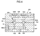
- FIG. 4 is a view showing further alternative embodiment of the present invention.
- the embodiment shown in FIG. 4 is directed to a case in which, in the inside of the fuel pump having a plurality of fuel outlet ports, a plurality of the fuel outlet ports are communicated with each other.
- a common rail and a piping system between the common rail and the fuel pump are not illustrated.
- the fuel pump 106 shown in FIG. 4 is of a type in which two high-pressure plungers 161 , 162 are formed in the inside of a casing block 107 .
- a fuel inlet passage 108 is further formed in the inside of the casing block 107 , and fuel which is supplied to the fuel inlet passage 108 from the outside the fuel pump 106 is respectively supplied to plunger chambers 161 A, 162 A of high-pressure plungers 161 , 162 by way of passages 109 , 110 .
- the passages 109 , 110 are interrupted from the outside of the casing block 107 by means of closing blocks 109 A, 110 A.
- the fuel outlet ports 163 , 164 are also formed corresponding to the high-pressure plungers 161 , 162 .
- the fuel outlet port 163 is communicated with the plunger chamber 161 A of the high-pressure plunger 161 by way of a passage 111
- the fuel outlet port 164 is communicated with the plunger chamber 162 A of the high-pressure plunger 162 by way of a passage 112 .
- the passages 111 , 112 are also formed in the inside of the casing block 107 .
- Numeral 180 shows a connection pipe which is provided for allowing the fuel outlet ports 163 , 164 to communicate with each other.
- the communication pipe 180 is formed in the inside of the casing block 107 , wherein the fuel outlet ports 163 , 164 are communicated with each other in the inside of the casing block 107 by the communication pipe 180 .
- the communication pipe 180 is interrupted from the outside of the casing block 107 by means of a closing block 180 A. Accordingly, by adopting the constitution shown in FIG. 4 , it is possible to obtain the operation and advantageous effects in the same manner as the respective embodiments shown in FIG. 2 and FIG. 3 .
Abstract
In a fuel supply device 1 in which high-pressure fuel in the inside of a common rail 2 which accumulates the high-pressure fuel supplied from a fuel pump 6 under pressure is supplied to an internal combustion engine by fuel injection valves, and the fuel pump 6 includes a plurality of high-pressure plungers 61 to 64 whose high-pressure-fuel injection timings are shifted from each other, a portion or all of high-pressure pipes 11 to 14 which connect fuel outlet ports 6P1 to 6P4 of high-pressure plungers 61 to 64 with the common rail 2 are connected with each other by connection pipes 30 to 33 thus establishing a state in which the high-pressure fuel from substantially one high-pressure plunger is supplied using the plurality of high-pressure pipes whereby the elevation of fuel pressures in the inside of the high-pressure pipes can be suppressed.
Description
The present invention relates to a fuel supply device which is configured to supply high-pressure fuel from a fuel pump to a common rail, to accumulate the high-pressure fuel in the common rail, and to supply the fuel inside the common rail to an internal combustion engine.
There has been known a fuel supply device which is constituted of a fuel pump, a common rail which accumulates a high-pressure fuel supplied under pressure from the fuel pump, and fuel injection valves which are provided for respective cylinders of an internal combustion engine and are capable of supplying the high-pressure fuel accumulated in the common rail, and is referred to as a common rail system. In this type of the fuel supply device, as shown in FIG. 1 of JP-A-2001-263198, respective outlet ports of the fuel pump and the common rail are connected with each other by way of two high-pressure pipes which are provided independently from each other, and the high-pressure fuel from the respective outlet ports are supplied to the common rail by way of these two high-pressure pipes.
In this manner, the fuel pump which arranges high-pressure generating portions in a row adopts piping in which the fuel pump and the rail are connected with each other by a high-pressure pipe for every cylinder and hence, with respect to the fuel pump which is required to allow a large quantity of fuel to pass therethrough, a flow rate per hour that is allocated to one high-pressure generating portion becomes considerably large. Accordingly, due to throttling of an inner-diameter portion of the high-pressure pipe which is connected to the high-pressure outlet portion, the pressure is elevated at an outlet portion thus giving rise to a drawback with respect to the reliability of the high-pressure generating portion.
That is, in the conventional fuel supply device, a pressure resistance design having a sufficient margin with respect to an upper limit of the pressure fluctuation is usually performed by taking a lifetime of a product into consideration. However, in case that the pressure fluctuation of the fuel injected from the fuel pump is large, it is necessary to increase the pressure resistance value of the whole system including a fuel injection valve, a common rail, a pipe which connects the fuel pump and the common rail, a pipe which connects the common rail and the fuel injection valve and the like to a value which exceeds the necessary pressure resistance. Although it may be possible to suppress the elevation of pressure by increasing an inner diameter of the pipe, there may be a case that the sufficient inner diameter cannot be ensured due to the restriction imposed on strength, a mounting size and the like of the pipe. Further, when the pressure fluctuation is large, there arise drawbacks such as the increase of weight attributed to the increase of a wall thickness of constitutional parts and the complication of the structure attributed to the pressure resistance design.
It is an object of the present invention to provide a fuel supply device which can overcome the above-mentioned drawbacks of the related art.
It is also an object of the present invention to provide a fuel supply device which can suppress the elevation of pressure in the inside of a high-pressure pipe in comparison with a related art.
It is another object of the present invention to provide a fuel supply device which can realize the reduction of weight and the miniaturization thereof.
To overcome the above-mentioned drawbacks, according to the present invention, in the constitution which supplies a high-pressure fuel which is pressurized by fuel pumps whose injection timings are shifted from each other to a common rail by way of a plurality of high pressure pipes, a portion or the whole high-pressure pipes are connected with each other by connection pipes between fuel outlet ports of the fuel pumps and a fuel input port of the common rail, it is possible to provide a state in which the high-pressure fuel from substantially one high-pressure generating part is supplied using a plurality of pipe passages thus suppressing the elevation of the fuel pressure inside the high pressure pipes.
The present invention is characterized in that in a fuel supply device which includes a fuel pump, a common rail which accumulates a high-pressure fuel which is supplied from the fuel pump under pressure, and a fuel injection valve which is capable of supplying the high-pressure fuel accumulated in the inside of the common rail to an internal combustion engine, wherein the fuel pump includes a plurality of high-pressure generating portions whose high-pressure-fuel injection timings are shifted from each other, the fuel supply device includes a plurality of high-pressure pipes which are provided corresponding to the plurality of high-pressure generating portions and connect fuel outlet ports of the corresponding high-pressure generating portions and the common rail, and a connection pipe which connects at least two or more high-pressure pipes out of the plurality of high-pressure pipes with each other in the vicinity of the corresponding fuel outlet ports.
The high-pressure fuel is supplied from the plurality of the high-pressure generating portions at different timings, and the high-pressure fuel is supplied to the inside of the common rail from the corresponding fuel outlet port through the high-pressure pipe which is connected to the fuel outlet port. Here, although the inner pressure of the high-pressure pipe is sharply elevated, a portion of the high-pressure fuel escapes to the separate high-pressure pipe which is connected to the high-pressure generating portion which is not at the high-pressure injection timing by way of the connection pipe. As the result, the elevation of the inner pressure of the high-pressure pipe can be suppressed to a low level compared to a corresponding conventional high-pressure pipe.
According to the present invention, with the provision of the connection pipe, the high-pressure fuel from the corresponding high-pressure generating portion is distributed into the plurality of high-pressure pipes and is supplied to the common rail and hence, the elevation of the pressure in the inside of the respective high-pressure pipes can be effectively suppressed. As a result, it is unnecessary to impart an extra strength to the fuel pump and the high-pressure pipe and hence, it is possible to realize the reduction of weight and the miniaturization of the device and the reduction of cost attributed to the reduction of weight and the miniaturization of the device. Further, it is possible to realize the enhancement of the reliability, the reduction of the driving torque and the enhancement of power efficiency.
The present invention is explained in conjunction with attached drawings for describing the invention in more detail.
In FIG. 1 , numeral 4 indicates a tank for accumulating fuel 5, numeral 6 indicates a fuel pump (a supply pump), and numeral 7 indicates a low-pressure pump which is provided to a low-pressure side of the fuel pump 6 as a feed pump. The fuel 5 in the inside of the tank 4 is pumped up by a low-pressure pump 7 by way of a fuel pipe 8. The low-pressure fuel from the low-pressure pump 7 passes through an oil supply passage 10 on which a flow rate control valve 9 for adjusting a quantity of fuel which is supplied to the fuel pump 6 is provided, and is supplied to suction valves V1, V2 of the fuel pump 6. Here, numeral 17 indicates a return oil passage, numeral 18 indicates a pressure valve which adjusts a front-side pressure of the flow-rate control valve 9, and numeral 19 indicates a return oil passage at the time of non-injection having a zero delivery orifice 20.
In this embodiment, the fuel pump 6 includes two high- pressure plungers 61, 62 which form high-pressure generating portions, wherein these high- pressure plungers 61, 62 are driven by cams 64, 65 which are fixed to a cam shaft 63 which is rotated by a rotating force from the internal combustion engine not shown in the drawing.
The high-pressure plunger 61 is configured such that a piston 61B is housed in the inside of a cylinder 61A in a reciprocating manner along an axis thereof. Due to a tappet 61C which is cooperatively operated with the cam 64, a piston 61B is reciprocated corresponding to the rotation of the cam 64 so as to pressurize the low-pressure fuel supplied to the inside of the plunger chamber 61D which is defined by the piston 61B by way of the suction valve V1. The high-pressure fuel obtained by such an operation is fed from an outlet check valve V3 which opens in the direction toward the common rail 2.
Here, an outlet port of the outlet check valve V3 constitutes a fuel outlet port 6P1 of the high-pressure plunger 61, and the high-pressure fuel from the high-pressure plunger 61 is fed to the inside of the common rail 2 by way of the high-pressure pipe 11 which is arranged between an inlet port 2P1 of the common rail 2 and the fuel outlet port 6P1.
Although the explanation has been made with respect to the constitution of the high-pressure plunger 61 side heretofore, the high-pressure plunger 62 side is also constituted in the same manner. That is, in the high-pressure plunger 62, a piston 62B is housed in the inside of a cylinder 62A in a reciprocating manner along an axis thereof. Due to a tappet 62C which is cooperatively operated with the cam 65, a piston 62B is reciprocated corresponding to the rotation of the cam 65. Here, the cam 64 and the cam 65 are mounted on the cam shaft 63 with their phases shifted from each other.
Accordingly, the low-pressure fuel which is supplied to the inside of the plunger chamber 62D defined by the piston 62B by way of the suction valve V2 is pressurized. The high-pressure fuel obtained by such an operation is fed from an outlet check valve V4 which opens in the direction toward the common rail 2. However, the injection timing lag is present between the injection of the high-pressure fuel from the high-pressure plunger 61 and the injection of the high-pressure fuel from the high-pressure plunger 62 thus eliminating the possibility of simultaneous injection of the high-pressure fuel.
Here, an outlet port of the outlet check valve V4 constitutes a fuel outlet port 6P2 of the high-pressure plunger 62, and the high-pressure fuel from the high-pressure plunger 62 is fed to the inside of the common rail 2 by way of the high-pressure pipe 12 which is arranged between an inlet port 2P2 of the common rail 2 and the fuel outlet port 6P2.
Due to the high-pressure fuel which is respectively injected from the high- pressure plungers 61 and 62, pressures act on the high- pressure pipes 11, 12 which are provided corresponding to the high- pressure plungers 61 and 62. To largely reduce such pressures, between the high- pressure pipes 11, 12, a connection pipe 30 which brings the high- pressure pipes 11, 12 into a communication state with each other is arranged.
In this embodiment, to make the high- pressure pipes 11, 12 communicate with each other at a position R1 close to the fuel outlet port 6P1 of the high-pressure pipe 11 and at a position R2 close to the fuel outlet port 6P2 of the high-pressure pipe 12, one end 30A of the connection pipe 30 is connected to the high-pressure pipe 11 at the position R1 and another end 30B of the connection pipe 30 is connected to the high-pressure pipe 12 at the position R2. By providing the connection pipe 30 between the high- pressure pipes 11, 12 as described above, when the high-pressure fuel is discharged from either one of the high- pressure plungers 61 and 62, the high-pressure fuel is supplied to the common rail 2 by way of both of the high- pressure pipes 11, 12 and hence, the pressures in the inside of the high- pressure pipes 11, 12 are largely lowered compared to a conventional case in which the connection pipe 30 is not provided.
As a result, when the fuel pump 6 is operated and the fuel is injected from the high- pressure plungers 61, 62 with the timing lag, each high-pressure fuel is distributed to the high- pressure pipes 11, 12 by the connection pipe 30 and is supplied to the common rail 2. Accordingly, the pressure resistance specification of the high- pressure pipes 11, 12 can be reduced compared to the corresponding pressure resistance specification of conventional high- pressure pipes 11, 12 and hence, it is possible to decrease wall thicknesses and inner diameter of the high- pressure pipes 11, 12 whereby the miniaturization and the reduction of weight of the high- pressure pipes 11, 12 can be realized. Further, the pressure reduction effect also influences the plunger chambers 61D, 62D of the high- pressure plungers 61, 62 and hence, stresses applied to the cylinders 61A, 62A and cams 64, 65 can be reduced whereby the miniaturization and the reduction of weight of the whole fuel pump 6 can be realized. As a result, the restriction imposed on mounting sizes can be reduced and the degree of freedom of the arrangement of parts can be increased.
Here, the connecting positions of the connection pipe 30 to the high- pressure pipes 11, 12 are not limited to positions explained in conjunction with the above-mentioned embodiment. That is, it is sufficient to select the connecting positions which can, when the high-pressure fuel is injected from either one of the high- pressure plungers 61, 62, eliminate an imbalance that a large pressure acts on only one of the high- pressure pipes 11, 12 due to such high-pressure fuel. For this end, it is preferable to select the connecting points close to the fuel outlet ports 6P1, 6P2. It is more preferable to select the fuel outlet ports 6P1, 6P2 as the connecting positions of the connection pipe 30 with the high- pressure pipes 11, 12.
Although one embodiment of the present invention shown in FIG. 1 has been explained heretofore, the present invention is not limited to this embodiment. For example, the embodiment shown in FIG. 1 shows the example in which the fuel pump 6 includes two high-pressure generating portions (the high-pressure plungers 61, 62), the number of the high-pressure generating portions of the fuel pump 6 is not limited to two and the fuel pump 6 may include an arbitrary number including three or more of high-pressure generating portions. When the fuel pump 6 includes three or more high-pressure generating portions in this manner, the connection pipe which connects the respective high-pressure pipes which are provided corresponding to the respective high-pressure generating portions may be arranged to connect at least two high-pressure generating portions out of these high-pressure generating portions.
As a result, in the constitution shown in FIG. 2 , each high-pressure fuel from the high- pressure plungers 61, 62 is distributed to the high- pressure pipes 11, 12. In the same manner, each high-pressure fuel from the high- pressure plungers 66, 67 is distributed to the high- pressure pipes 13, 14. Here, in the embodiment shown in FIG. 2 , it is not necessary to provide the injection timing lag to all of the high- pressure plungers 61, 62, 66, 67 and it is sufficient that the injection timing is shifted only between two high-pressure plungers which are connected by the connection pipes 31, 32.
The fuel pump 106 shown in FIG. 4 is of a type in which two high- pressure plungers 161, 162 are formed in the inside of a casing block 107. A fuel inlet passage 108 is further formed in the inside of the casing block 107, and fuel which is supplied to the fuel inlet passage 108 from the outside the fuel pump 106 is respectively supplied to plunger chambers 161A, 162A of high- pressure plungers 161, 162 by way of passages 109, 110. The passages 109, 110 are interrupted from the outside of the casing block 107 by means of closing blocks 109A, 110A.
In the casing block 107, the fuel outlet ports 163, 164 are also formed corresponding to the high- pressure plungers 161, 162. The fuel outlet port 163 is communicated with the plunger chamber 161A of the high-pressure plunger 161 by way of a passage 111, while the fuel outlet port 164 is communicated with the plunger chamber 162A of the high-pressure plunger 162 by way of a passage 112. Here, the passages 111, 112 are also formed in the inside of the casing block 107.
As has been described heretofore, according to the present invention, it is possible to realize the miniaturization and the reduction of weight of the fuel pump thus contributing to the improvement of the fuel supply device.
Claims (1)
1. A fuel supply device (1) comprising:
a fuel pump (6);
a common rail (2) which accumulates a high-pressure fuel which is supplied from the fuel pump (6) under pressure; and
a fuel injection valve (3) which is capable of supplying the high-pressure fuel accumulated in the inside of the common rail (2) to an internal combustion engine, the fuel pump (6) including a plurality of high-pressure generating portions (61, 62, 66 67) whose high-pressure-fuel injection timings are shifted from each other, wherein
the fuel supply device (1) includes a plurality of high-pressure pipes (11 to 14) which are provided corresponding to the plurality of high-pressure generating portions (61, 62, 66, 67) and connect fuel outlet ports (6P1 to 6P4) of the corresponding high-pressure generating portions (61, 62, 66, 67) with corresponding inlet ports (2P1 to 2P4) of the common rail (2), and a connection pipe (30 to 33) which connects at least two or more high-pressure pipes (11, 12, 12, 13, 13, 14) out of the plurality of high-pressure pipes (11 to 14) with each other in the vicinity of the corresponding fuel outlet ports (6P1 to 6P4);
characterized in that:
each of the high-pressure pipes (11 to 14) is provided between one inlet port (2P1 to 2P4) and only one of the outlet ports (6P1 to 6P4), wherein each of the high-pressure pipes (11 to 14) is directly connected to only one high-pressure generating portion (61, 62, 66, 67) via the corresponding fuel outlet port (6P1 to 6P4) and an outlet valve (V3, V4) arranged in the fuel pump (6); and
the connection pipe (30 to 33) is arranged to directly connect the at least two or more high-pressure pipes (11 to 14) with each other between the both ends of each of the at least two or more high-pressure pipes (11 to 14).
Applications Claiming Priority (3)
| Application Number | Priority Date | Filing Date | Title |
|---|---|---|---|
| JP2004062152 | 2004-03-05 | ||
| JP2004-62152 | 2004-05-03 | ||
| PCT/JP2005/004159 WO2005085625A1 (en) | 2004-03-05 | 2005-03-03 | Fuel supply device |
Publications (2)
| Publication Number | Publication Date |
|---|---|
| US20080041341A1 US20080041341A1 (en) | 2008-02-21 |
| US7431019B2 true US7431019B2 (en) | 2008-10-07 |
Family
ID=34918104
Family Applications (1)
| Application Number | Title | Priority Date | Filing Date |
|---|---|---|---|
| US10/591,148 Active US7431019B2 (en) | 2004-03-05 | 2005-03-03 | Fuel supply device |
Country Status (7)
| Country | Link |
|---|---|
| US (1) | US7431019B2 (en) |
| EP (1) | EP1722097B1 (en) |
| JP (1) | JP4177406B2 (en) |
| KR (1) | KR100784122B1 (en) |
| CN (1) | CN100497933C (en) |
| DE (1) | DE602005013369D1 (en) |
| WO (1) | WO2005085625A1 (en) |
Cited By (2)
| Publication number | Priority date | Publication date | Assignee | Title |
|---|---|---|---|---|
| US20100043759A1 (en) * | 2007-01-08 | 2010-02-25 | Kylstroem Kim | Fuel pump and a method for controlling a fuel pump |
| WO2011109325A2 (en) * | 2010-03-05 | 2011-09-09 | Caterpillar Inc. | Range of engines using common rail fuel system with pump and rail assemblies having common components |
Families Citing this family (9)
| Publication number | Priority date | Publication date | Assignee | Title |
|---|---|---|---|---|
| DE102007006865A1 (en) * | 2007-02-12 | 2008-08-14 | Siemens Ag | Internal combustion engine controlling method for use in motor vehicle, involves operating high-pressure pumps in normal mode of operation, in which two pumps together supply fuel to pressure reservoir |
| FR2914959B1 (en) * | 2007-04-13 | 2013-03-08 | Siemens Automotive Hydraulics Sa | IMPROVEMENT TO HIGH-PRESSURE FUEL SUPPLY DEVICES BY TRANSFER PUMP |
| ITMI20092219A1 (en) * | 2009-12-17 | 2011-06-18 | Bosch Gmbh Robert | FUEL SUPPLY SYSTEM FOR A DIESEL CYCLE ENGINE |
| CN103244329A (en) * | 2013-04-28 | 2013-08-14 | 哈尔滨工程大学 | High-pressure common-rail fuel system with electric monoblock pumps |
| CN105637211B (en) * | 2013-10-14 | 2019-06-04 | 沃尔沃卡车集团 | Fuel system for internal combustion engine |
| CN106246424B (en) * | 2016-08-29 | 2019-07-30 | 潍柴动力股份有限公司 | High-pressure oil pump, engine fuel oil system and engine |
| CN109630332B (en) * | 2018-12-14 | 2020-06-19 | 重庆军通汽车有限责任公司 | Fuming vehicle suitable for operation in different altitude environments |
| CN109654528B (en) * | 2018-12-14 | 2020-05-08 | 重庆军通汽车有限责任公司 | Fuel oil system of smoke generator |
| JP2023008574A (en) * | 2021-07-06 | 2023-01-19 | 三菱重工エンジン&ターボチャージャ株式会社 | Fuel pump |
Citations (15)
| Publication number | Priority date | Publication date | Assignee | Title |
|---|---|---|---|---|
| US4016719A (en) * | 1975-03-30 | 1977-04-12 | Technion Research And Development Foundation, Ltd. | Hydrostatic transmission system |
| US4459963A (en) * | 1981-03-28 | 1984-07-17 | Robert Bosch Gmbh | Electrically controlled fuel injection apparatus for multi-cylinder internal combustion engines |
| US4621605A (en) * | 1983-12-30 | 1986-11-11 | Cummins Engine Company, Inc. | Positive displacement fuel injection system |
| JPH0472455A (en) | 1990-07-12 | 1992-03-06 | Nippondenso Co Ltd | Safety valve for fuel injection device |
| US5094216A (en) * | 1987-09-16 | 1992-03-10 | Nippondenso Co., Ltd. | Variable discharge high pressure pump |
| US5404855A (en) * | 1993-05-06 | 1995-04-11 | Cummins Engine Company, Inc. | Variable displacement high pressure pump for fuel injection systems |
| US5579640A (en) * | 1995-04-27 | 1996-12-03 | The United States Of America As Represented By The Administrator Of The Environmental Protection Agency | Accumulator engine |
| JPH1144276A (en) | 1997-07-29 | 1999-02-16 | Unisia Jecs Corp | Fuel injection device |
| US6053147A (en) * | 1998-03-02 | 2000-04-25 | Cummins Engine Company, Inc. | Apparatus and method for diagnosing erratic pressure sensor operation in a fuel system of an internal combustion engine |
| US6112710A (en) * | 1997-11-21 | 2000-09-05 | Diesel Engine Retarders, Inc. | Method and system start-up apparatus for removing air and debris from a valve actuation system |
| JP2002295337A (en) | 2001-03-29 | 2002-10-09 | Nippon Soken Inc | Fuel injection device for internal combustion engine |
| US20030010319A1 (en) * | 2000-02-07 | 2003-01-16 | Masayori Ishimoto | Fuel injection device |
| US20040129255A1 (en) * | 2003-01-08 | 2004-07-08 | Stuhldreher Mark Spencer | Hydraulically intensified high pressure fuel system for common rail application |
| US20040154594A1 (en) * | 2003-02-06 | 2004-08-12 | Toyota Jidosha Kabushiki Kaisha | Fuel supply system for internal combustion engine |
| US20060120880A1 (en) * | 2004-11-30 | 2006-06-08 | Caterpillar Inc. | Variable discharge fuel pump |
Family Cites Families (3)
| Publication number | Priority date | Publication date | Assignee | Title |
|---|---|---|---|---|
| JPS5312336Y2 (en) * | 1972-12-19 | 1978-04-04 | ||
| DE50101950D1 (en) * | 2000-03-01 | 2004-05-19 | Waertsilae Nsd Schweiz Ag | Supply device for a common rail system |
| EP1130251A1 (en) * | 2000-03-01 | 2001-09-05 | Wärtsilä NSD Schweiz AG | Pump arrangement for a common rail injection system |
-
2005
- 2005-03-03 CN CNB2005800070658A patent/CN100497933C/en not_active Expired - Fee Related
- 2005-03-03 US US10/591,148 patent/US7431019B2/en active Active
- 2005-03-03 WO PCT/JP2005/004159 patent/WO2005085625A1/en active Application Filing
- 2005-03-03 EP EP05720430A patent/EP1722097B1/en not_active Expired - Fee Related
- 2005-03-03 KR KR1020067020442A patent/KR100784122B1/en not_active IP Right Cessation
- 2005-03-03 DE DE602005013369T patent/DE602005013369D1/en active Active
- 2005-03-03 JP JP2006510806A patent/JP4177406B2/en active Active
Patent Citations (16)
| Publication number | Priority date | Publication date | Assignee | Title |
|---|---|---|---|---|
| US4016719A (en) * | 1975-03-30 | 1977-04-12 | Technion Research And Development Foundation, Ltd. | Hydrostatic transmission system |
| US4459963A (en) * | 1981-03-28 | 1984-07-17 | Robert Bosch Gmbh | Electrically controlled fuel injection apparatus for multi-cylinder internal combustion engines |
| US4621605A (en) * | 1983-12-30 | 1986-11-11 | Cummins Engine Company, Inc. | Positive displacement fuel injection system |
| US5094216A (en) * | 1987-09-16 | 1992-03-10 | Nippondenso Co., Ltd. | Variable discharge high pressure pump |
| JPH0472455A (en) | 1990-07-12 | 1992-03-06 | Nippondenso Co Ltd | Safety valve for fuel injection device |
| US5404855A (en) * | 1993-05-06 | 1995-04-11 | Cummins Engine Company, Inc. | Variable displacement high pressure pump for fuel injection systems |
| US5579640A (en) * | 1995-04-27 | 1996-12-03 | The United States Of America As Represented By The Administrator Of The Environmental Protection Agency | Accumulator engine |
| JPH1144276A (en) | 1997-07-29 | 1999-02-16 | Unisia Jecs Corp | Fuel injection device |
| US6112710A (en) * | 1997-11-21 | 2000-09-05 | Diesel Engine Retarders, Inc. | Method and system start-up apparatus for removing air and debris from a valve actuation system |
| US6053147A (en) * | 1998-03-02 | 2000-04-25 | Cummins Engine Company, Inc. | Apparatus and method for diagnosing erratic pressure sensor operation in a fuel system of an internal combustion engine |
| US20030010319A1 (en) * | 2000-02-07 | 2003-01-16 | Masayori Ishimoto | Fuel injection device |
| JP2002295337A (en) | 2001-03-29 | 2002-10-09 | Nippon Soken Inc | Fuel injection device for internal combustion engine |
| US20040129255A1 (en) * | 2003-01-08 | 2004-07-08 | Stuhldreher Mark Spencer | Hydraulically intensified high pressure fuel system for common rail application |
| US6786205B2 (en) * | 2003-01-08 | 2004-09-07 | The United States Of America As Represented By The Environmental Production Agency | Hydraulically intensified high pressure fuel system for common rail application |
| US20040154594A1 (en) * | 2003-02-06 | 2004-08-12 | Toyota Jidosha Kabushiki Kaisha | Fuel supply system for internal combustion engine |
| US20060120880A1 (en) * | 2004-11-30 | 2006-06-08 | Caterpillar Inc. | Variable discharge fuel pump |
Non-Patent Citations (1)
| Title |
|---|
| International Search Report No. PCT/JP2005/004159, dated Jun. 7, 2005, 4 pgs. |
Cited By (4)
| Publication number | Priority date | Publication date | Assignee | Title |
|---|---|---|---|---|
| US20100043759A1 (en) * | 2007-01-08 | 2010-02-25 | Kylstroem Kim | Fuel pump and a method for controlling a fuel pump |
| US7975674B2 (en) * | 2007-01-08 | 2011-07-12 | Scania Cv Ab (Publ) | Fuel pump and a method for controlling a fuel pump |
| WO2011109325A2 (en) * | 2010-03-05 | 2011-09-09 | Caterpillar Inc. | Range of engines using common rail fuel system with pump and rail assemblies having common components |
| WO2011109325A3 (en) * | 2010-03-05 | 2011-12-01 | Caterpillar Inc. | Range of engines using common rail fuel system with pump and rail assemblies having common components |
Also Published As
| Publication number | Publication date |
|---|---|
| WO2005085625A1 (en) | 2005-09-15 |
| EP1722097B1 (en) | 2009-03-18 |
| US20080041341A1 (en) | 2008-02-21 |
| KR100784122B1 (en) | 2007-12-12 |
| KR20060122976A (en) | 2006-11-30 |
| EP1722097A4 (en) | 2007-04-11 |
| JP4177406B2 (en) | 2008-11-05 |
| JPWO2005085625A1 (en) | 2008-01-24 |
| CN100497933C (en) | 2009-06-10 |
| CN1961144A (en) | 2007-05-09 |
| EP1722097A1 (en) | 2006-11-15 |
| DE602005013369D1 (en) | 2009-04-30 |
Similar Documents
| Publication | Publication Date | Title |
|---|---|---|
| US7431019B2 (en) | Fuel supply device | |
| JP4088738B2 (en) | Fuel injection pump | |
| KR100689344B1 (en) | Fuel pump and fuel feeding device using the fuel pump | |
| US7118350B2 (en) | Radial piston pump | |
| US8011349B2 (en) | Fuel injection system | |
| US9512836B2 (en) | Fuel pump for an internal combustion engine | |
| US9103307B2 (en) | High-pressure pump arrangement | |
| KR20060067837A (en) | Fuel supply device in form of a common-rail-system for several cylinders of an internal combustion engine | |
| WO2005068823A1 (en) | Fuel supply pump | |
| US6817841B2 (en) | High-pressure fuel pump for internal combustion engine with improved partial-load performance | |
| WO2009053364A1 (en) | Fuel injection system with a high-pressure pump lubricated with the fuel, and associated pump unit | |
| JPWO2002038941A1 (en) | Pressure accumulating distribution type fuel injection pump | |
| JP2006500504A (en) | Fuel injection device for internal combustion engine | |
| KR20110051826A (en) | High pressure fuel pump integrally provided with discharge valve and pressure relief valve | |
| US20140338637A1 (en) | Common rail system having mechanical unit pumps | |
| US11525427B2 (en) | High pressure fuel pump and fuel supply system | |
| KR101687036B1 (en) | Suction valve of a fuel supply system of an internal combustion engine | |
| JP2008261333A (en) | Improvement of high pressure fuel supply device by feed pump | |
| JP3884665B2 (en) | Accumulated distribution fuel injection pump | |
| CN114450486A (en) | Modular gear pump for supplying fuel to a pump unit of an internal combustion engine | |
| US6364631B1 (en) | Pump apparatus for hydraulically powered fuel injection systems | |
| JP3648195B2 (en) | Head structure of accumulator-type distributed injection pump | |
| WO2013098119A1 (en) | High pressure pump and system | |
| CN113994090A (en) | Pump, in particular high-pressure fuel pump | |
| JP3745999B2 (en) | Accumulated distribution fuel injection pump |
Legal Events
| Date | Code | Title | Description |
|---|---|---|---|
| AS | Assignment |
Owner name: BOSCH CORPORATION, JAPAN Free format text: ASSIGNMENT OF ASSIGNORS INTEREST;ASSIGNOR:KUBOTA, KAZUYA;REEL/FRAME:018388/0471 Effective date: 20060830 |
|
| STCF | Information on status: patent grant |
Free format text: PATENTED CASE |
|
| FPAY | Fee payment |
Year of fee payment: 4 |
|
| FPAY | Fee payment |
Year of fee payment: 8 |
|
| MAFP | Maintenance fee payment |
Free format text: PAYMENT OF MAINTENANCE FEE, 12TH YEAR, LARGE ENTITY (ORIGINAL EVENT CODE: M1553); ENTITY STATUS OF PATENT OWNER: LARGE ENTITY Year of fee payment: 12 |