US7433185B1 - Integrated display computer stand with integrated peripherals - Google Patents
Integrated display computer stand with integrated peripherals Download PDFInfo
- Publication number
- US7433185B1 US7433185B1 US11/267,490 US26749005A US7433185B1 US 7433185 B1 US7433185 B1 US 7433185B1 US 26749005 A US26749005 A US 26749005A US 7433185 B1 US7433185 B1 US 7433185B1
- Authority
- US
- United States
- Prior art keywords
- stand
- base
- tower
- integrated display
- display computer
- Prior art date
- Legal status (The legal status is an assumption and is not a legal conclusion. Google has not performed a legal analysis and makes no representation as to the accuracy of the status listed.)
- Expired - Fee Related, expires
Links
Images


Classifications
-
- G—PHYSICS
- G06—COMPUTING; CALCULATING OR COUNTING
- G06F—ELECTRIC DIGITAL DATA PROCESSING
- G06F1/00—Details not covered by groups G06F3/00 - G06F13/00 and G06F21/00
- G06F1/16—Constructional details or arrangements
- G06F1/1613—Constructional details or arrangements for portable computers
- G06F1/1632—External expansion units, e.g. docking stations
-
- F—MECHANICAL ENGINEERING; LIGHTING; HEATING; WEAPONS; BLASTING
- F16—ENGINEERING ELEMENTS AND UNITS; GENERAL MEASURES FOR PRODUCING AND MAINTAINING EFFECTIVE FUNCTIONING OF MACHINES OR INSTALLATIONS; THERMAL INSULATION IN GENERAL
- F16M—FRAMES, CASINGS OR BEDS OF ENGINES, MACHINES OR APPARATUS, NOT SPECIFIC TO ENGINES, MACHINES OR APPARATUS PROVIDED FOR ELSEWHERE; STANDS; SUPPORTS
- F16M11/00—Stands or trestles as supports for apparatus or articles placed thereon Stands for scientific apparatus such as gravitational force meters
- F16M11/20—Undercarriages with or without wheels
- F16M11/22—Undercarriages with or without wheels with approximately constant height, e.g. with constant length of column or of legs
-
- G—PHYSICS
- G06—COMPUTING; CALCULATING OR COUNTING
- G06F—ELECTRIC DIGITAL DATA PROCESSING
- G06F1/00—Details not covered by groups G06F3/00 - G06F13/00 and G06F21/00
- G06F1/16—Constructional details or arrangements
- G06F1/1601—Constructional details related to the housing of computer displays, e.g. of CRT monitors, of flat displays
- G06F1/1605—Multimedia displays, e.g. with integrated or attached speakers, cameras, microphones
-
- G—PHYSICS
- G06—COMPUTING; CALCULATING OR COUNTING
- G06F—ELECTRIC DIGITAL DATA PROCESSING
- G06F1/00—Details not covered by groups G06F3/00 - G06F13/00 and G06F21/00
- G06F1/16—Constructional details or arrangements
- G06F1/18—Packaging or power distribution
- G06F1/181—Enclosures
-
- G—PHYSICS
- G07—CHECKING-DEVICES
- G07G—REGISTERING THE RECEIPT OF CASH, VALUABLES, OR TOKENS
- G07G1/00—Cash registers
- G07G1/0018—Constructional details, e.g. of drawer, printing means, input means
-
- F—MECHANICAL ENGINEERING; LIGHTING; HEATING; WEAPONS; BLASTING
- F16—ENGINEERING ELEMENTS AND UNITS; GENERAL MEASURES FOR PRODUCING AND MAINTAINING EFFECTIVE FUNCTIONING OF MACHINES OR INSTALLATIONS; THERMAL INSULATION IN GENERAL
- F16M—FRAMES, CASINGS OR BEDS OF ENGINES, MACHINES OR APPARATUS, NOT SPECIFIC TO ENGINES, MACHINES OR APPARATUS PROVIDED FOR ELSEWHERE; STANDS; SUPPORTS
- F16M2200/00—Details of stands or supports
- F16M2200/08—Foot or support base
Definitions
- the benefits provided by a fanless integrated display computer with peripherals include increased reliability and lower maintenance costs.
- the device never suffers from unreliability or damage due to fan failure.
- the natural convection process results in very light air inflow and almost completely eliminates internal dust build-up. There is no build-up of dust that is normally caused by the use of fans and that often leads to fan failures.
- maintenance costs associated with protecting components from fan failures, repairing and replacing fans, and repairing and replacing components damaged by fan failures are eliminated. Maintenance costs associated with repair and replacement of peripherals devices are also reduced because the peripherals are secured within and protected by the housing unit.
- an opening in the base door may be created by removing a cutout portion 302 .
- External cords or cables that attach to board ports inside the stand base may extend through the opening at the bottom of the base door.
- the base door and base stand may be designed so the inner compartment that is formed when the base door is attached to the base stand is sufficiently large to provide strain relief for any cords or cables that are plugged into the inside ports.
- FIG. 3D provides a view of the exposed area when the base door is attached to the stand base.
Abstract
A stand with integrated peripherals for an integrated display computer. The peripherals are enclosed in a stand housing unit. Only the portion of the peripheral or peripheral interface with which a user interacts is accessible through the stand housing unit. The remaining components are hidden within the housing unit. Various types of peripherals such a CD-ROM or DVD drive may be installed in the base of the stand. Other types of peripherals such as a printer may be installed in the tower of the stand. The base and tower may be combined to form a complete stand. Power cords and cables may extend through the back or bottom of the stand and are protected by the stand base. The complete stand, which can accommodate an integrated display computer, gives each integrated display computer a similar, finished appearance regardless of which peripherals, if any, are enclosed in the stand.
Description
This application is a continuation-in-part application under 37 CFR 1.53(b) of U.S. patent application Ser. No. 11/131,052, entitled Integrated Display Computer with Peripherals filed on May 17, 2005 now U.S. Pat. No. 7,397,659, which is incorporated herein by reference, which is a continuation-in-part application under 37 CFR 1.53(b) of U.S. patent application Ser. No. 10/937,976, entitled Fanless Computer With Integrated Display filed on Sep. 10, 2004, now U.S. Pat. No. 7,072,179 issued on Jul. 4, 2006, which is incorporated herein by reference.
The present invention relates generally to integrated computer display stands. More specifically, the present invention is directed to a stand for an integrated display computer that houses peripheral devices such as a printer, CD-ROM or DVD drive, and USB port.
Integrated display computers provide basic computer and monitor functionality in a compact package. Although they provide a great deal of functionality in a single package, the functionality is typically limited to the functionality of a simple desktop or tower computer and display unit. Additional functionality, which is often provided by peripherals that are connected to ports on the computer or display unit, is excluded from the integrated display computer because the additional devices increase the size or space needed for the unit so that it is no longer small and compact.
To accommodate the peripherals that some users may need, most integrated display computer manufacturers simply provide ports at various locations on the computer to provide connections for external devices. In some instances, a cable is used to connect the peripheral to the computer. The ports may be exposed or they may have a hinged cover that opens to accommodate the peripheral. While it is possible to attach and detach different peripherals, the connected peripherals require the availability of additional space around the unit to accommodate both the external device and in some cases, a cable. The resulting package is no longer compact. Furthermore, the result can be unsightly as various devices, and possibly cables, surround the integrated display computer. If the ports have covers, the covers are open and the devices or cables extend from the ports. If the ports do not have covers and devices are not attached to the ports, the ports simply remain exposed. The appearance of the integrated display computer may be altered dramatically as peripherals extend from around the computer. If the computer and devices are used in a commercial setting, the combination of components may appear complex and difficult to operate and therefore, unappealing to users.
In addition to changes in appearance, the use of ports and external devices can provide operational challenges. The ports allow devices to be attached and detached very easily. However, the ability to easily attach peripherals means they are subject to inadvertent detachment. If the integrated display computer is in use in a commercial setting, the peripherals may be subjected to heavy and continuous use increasing the likelihood that a peripheral becomes detached. Some users may simply be tempted to purposefully remove a peripheral. Whether peripheral devices are removed accidentally or purposefully, the expense of operating the computer increases due to increased device maintenance and replacement costs.
To increase the functionality of an integrated display computer, a housing unit as described in U.S. patent application Ser. No. 11/131,052, entitled Integrated Display Computer with Peripherals can be used to attach peripherals to either or both sides of an integrated display computer. The housing unit is based on a universal attachment design so that the integrated display computer can accept different types of peripherals. The peripherals are installed in a peripheral housing unit that is attached or affixed to a side of the computer which is designed to accept the housing unit. The housing unit comprises an end cap and a shroud as well as internal components including a mounting bracket that are assembled to complete the unit. The assembled peripheral housing unit is then attached or affixed to the computer. Peripheral-containing housing units may be attached to either or both sides of the computer. In the event only one peripheral is needed or no peripherals are needed, a “blank” housing unit which does not contain a peripheral device may be attached to the computer. The integrated display computer can accept a housing unit on each side regardless of whether it contains a peripheral.
The peripheral housing unit described in U.S. patent application Ser. No. 11/131,052 may further be used with a fanless integrated display computer. One such fanless integrated display computer that is especially well-suited to use for this purpose is described in U.S. patent application Ser. No. 10/937,976, entitled Fanless Computer With Integrated Display, now U.S. Pat. No. 7,072,179 issued on Jul. 4, 2006. The fanless integrated display computer described in U.S. patent application Ser. No. 10/937,976 has several passive cooling design features so that it is fanless and therefore, silent. It comprises a unique heat sink that supports the entire enclosure and causes heat in the device to dissipate through vents. The motherboard assembly attaches directly to the heat sink to facilitate thermal transfer characteristics so that components are cooled without the need for a fan. The heat sink further serves as the entire supporting structure of the circuit board assembly and is designed and incorporated into the device so that any stress experienced by the heat sink is not transferred to the solder joints. The entire PCB assembly, which comprises the processor and chipset, moves with the heat sink.
The benefits provided by a fanless integrated display computer with peripherals include increased reliability and lower maintenance costs. The device never suffers from unreliability or damage due to fan failure. The natural convection process results in very light air inflow and almost completely eliminates internal dust build-up. There is no build-up of dust that is normally caused by the use of fans and that often leads to fan failures. As a result, maintenance costs associated with protecting components from fan failures, repairing and replacing fans, and repairing and replacing components damaged by fan failures are eliminated. Maintenance costs associated with repair and replacement of peripherals devices are also reduced because the peripherals are secured within and protected by the housing unit.
A fanless integrated display computer with peripherals is silent and therefore, suitable for many applications including use in hospitals, libraries, or any other location where the presence of noise and dust is a concern. It comprises an integrated display with peripherals attached to the sides of the display so it is very compact and suitable for use in locations where the availability of space is a concern.
In one application of the fanless integrated display computer, the computer may be mounted on a retail store shelf to provide product information to consumers shopping at a retail establishment. With the multitude of products available to today's consumer, and the wealth of information that now commonly exists with respect to such products, it is desirable for retail establishments to provide the consumer with an on-site and efficient means of accessing this additional information. Retailers can present the consumer with all, or a large portion of, such information at a single source. For example, when considering a foodstuff, typical information may be related to rebate instructions, the existence of coupons, special pricing, or features. The information may also be more product specific, such as the product's nutritional information, for example. Depending on the particular type of products considered and the level of detail desired, the amount of information that may be provided can be substantial. A fanless integrated display computer with a peripheral housing unit comprising a bar code scanner facilitates a consumer's access to product information by allowing the consumer to simply scan the product of interest. The amount of information that may be provided via the computer display is virtually endless.
Although a fanless integrated display computer with peripherals is suitable for many commercial applications because of its reliability and durability, its compact size may not permit it to accommodate all peripherals that may be desired for a commercial application. Size limitations may impact the number of integrated peripherals that can be integrated into the display. Furthermore, some peripherals such as printers and CD-ROM or DVD drives may simply be too large to attach to a side, top, or bottom of an integrated display computer. If the peripheral cannot be attached to the integrated display using a housing such as the one described in U.S. patent application Ser. No. 11/131,052 or if size limitations prohibit integration of needed peripherals into the display, then the prior art method of attaching peripherals using a port, which detracts from the appearance of the integrated display computer and increases maintenance costs, is the only option for increasing the number of peripherals. Therefore, additional methods for integrating peripherals with an integrated display computer are needed.
The present invention is a stand with integrated peripherals for an integrated display computer. A stand for an integrated display computer that houses peripheral devices such as a printer, CD-ROM or DVD drive, and USB port provides additional functionality for the computer without detracting from the appearance of the unit.
The stand comprises a base and a tower, each of which may house a peripheral device. The complete stand is formed when the base and tower are attached. An integrated display computer may then be attached to the tower to form a complete unit with features and functionality for interacting with the peripherals. Only those portions of the peripherals that a user needs to access are exposed. In certain instances, such as with a printer, the peripheral may be completely inaccessible to a user. Only the paper dispensed by the printer is accessible. The stand therefore, protects the peripherals thereby making the unit attractive and cost effective to maintain.
Referring to FIGS. 1A and 1B , rearward and frontward perspective views of an integrated display computer attached to a stand with integrated peripherals for an example embodiment of the present invention are shown. Referring to FIG. 1A , the completed unit 100 comprises an integrated display computer 102 and a stand 104 that houses one or more peripherals. The stand 104 comprises a tower 106 and a base 108, each of which may house a peripheral. For example, as shown in FIG. 1B , a base 108 may comprise a USB port 110 and a CD-ROM drive 112. An opening in the base 111 allows a user to access the housed peripherals. A printer may be housed in the tower 106 which further comprises a printer bay access door 120 for accessing the printer and paper. The printer may be used to print receipts or other information that is then dispensed to a user from the tower. Connectors such as power cords or cables for the integrated display computer or peripherals may extend through an aperture 116 that is created when a base door 114 is installed at the back of the stand base 108. Finally, the stand base 108 may comprise a t-lock or other type of locking slot 118 that comprises a chain or cable to secure the unit to a table, shelf, or other permanent object to discourage theft.
Referring to FIG. 2A , an exploded view of a stand for housing peripherals for an example embodiment of the present invention is shown. The peripheral devices shown for purposes of illustration in the example embodiment of FIG. 2A are a printer, a USB port, and a CD-ROM drive. Alternatively, other types of input/output devices or peripherals, such as bar code scanners or magnetic card readers, may be assembled into the stand of the present invention. Various types of USB peripherals as well as custom peripherals that use a serial port or a custom interface could also be integrated into the stand peripheral housing unit of the present invention.
The stand for a printer, USB port, and CD-ROM drive comprises the following components: right tower portion 200 and left tower portion 202 for holding a print head bracket 204; a print head bracket 204 for holding a printer; printer paper 206; a printer bay access door 120; a stand base 108 for housing a USB port for an external device and CD-ROM drive and a chute 109 for directing printer paper dispensed from the tower; a bottom EMI plate 216; a base door 114; a base board 212 with circuitry for controlling one or more peripherals; a USB adapter board 214 for an external USB device; a power board 210; and a top EMI plate 208.
The components of the stand base 108 are assembled as described below, although not necessarily in the order recited. The top EMI plate 208 is attached to the stand base 108 using fasteners and openings 228 on the EMI plate 208 and standoffs on the stand base 108. The power board 210 is placed below the top EMI plate 208. The base board 212 and USB adapter board 214 are then installed by attaching each component to the stand base 108 using fasteners and openings on the components 226, 215 and standoffs on the stand base 108. The base board may accommodate a peripheral such as a CD-ROM or DVD drive. Rubber feet 232 are attached to openings 222 on the bottom EMI plate 218 and the bottom EMI plate 218 is attached to the stand base 108 using opening 224 on the bottom EMI plate 218 and standoffs on the stand base 108. Power cords and/or cables (connectors) may then be inserted into ports on the base board 212. The base door 114 may then be attached to the stand base 108 using a thumbscrew 234 that is accommodated by a standoff on the stand base 108. The external connectors such as cords or cables may extend through an aperture at the back of the stand base 108 that is created when the base door 114 is attached to the stand base 108 or through an opening on the bottom of the stand base 108 that is created when a cutout portion of the base door 114 bottom is removed.
The components of the tower for housing the print head bracket 204 and printer paper 206 are assembled as described below, although not necessarily in the order recited. The print head bracket 204 is inserted between a left tower 200 and a right tower 202 that connect to form a housing for the print head bracket 204 and paper 206. The print head bracket 204 comprises means such as tabs or flanges for attaching each side of the bracket to a tower. The assembled tower then connects to the stand base 108 to form a complete or integrated stand 104 as shown in FIG. 2B . As shown in FIG. 2A , a printer bay access door 120 with clips or tabs 232 attaches to the back of the assembled tower to complete the unit and provide access to the printer and paper during operation. Multiple screws that are inserted through openings 230 in the left tower 200 and right tower 202 allow an integrated display computer to be attached to the complete or integrated stand 104. Guides 238 on each tower facilitate the process of attaching the integrated display computer.
Referring to FIG. 2B , a complete stand 104 which is ready to accommodate an integrated display computer comprises a stand base 108, a tower 106, guides 238 to facilitate the process of attaching an integrated display computer, and screws 236 for attaching the integrated display computer to the stand 104. Integrated display computers of various sizes may be attached to the stand and may be oriented in a landscape mode or a portrait mode.
Referring to FIGS. 3A-3E , various views of a base door of the stand shown in FIG. 2B can be seen. The base door provides a means for accommodating external connectors such as cords or cables that internal electronic componentry requires to operate. The base door comprises an opening 300 as shown in FIGS. 3B , 3C, and 3E to accommodate a thumbscrew for attaching the base door to the base stand. Referring again to FIG. 1A , the stand base 108 is designed to accommodate the base door 114 such that an aperture 116 through which external cords or cables may extend is created when the base door 114 is attached to the stand base 108. Referring to FIGS. 3B , 3C, and 3E, an opening in the base door may be created by removing a cutout portion 302. External cords or cables that attach to board ports inside the stand base may extend through the opening at the bottom of the base door. The base door and base stand may be designed so the inner compartment that is formed when the base door is attached to the base stand is sufficiently large to provide strain relief for any cords or cables that are plugged into the inside ports. FIG. 3D provides a view of the exposed area when the base door is attached to the stand base.
Various views of a bottom EMI plate of the assembly shown in FIG. 2A can be observed by reference to FIGS. 4A-4D . As shown in FIGS. 4A and 4D , the bottom EMI plate 218 comprises openings 222 for inserting rubber feet through the bottom. The bottom EMI plate 218 when attached to the stand base provides a bottom surface for the stand. Additional openings 224 are used to accommodate fasteners to attach the bottom EMI plate 218 to standoffs on the stand base. Another set of openings 220 may be used to attach the stand to a table top or other horizontal surface. Therefore, the entire unit may be secured to a table top or other surface to prevent movement of the unit while it is operational and to prevent theft. Finally, another opening in the middle 400 may be used to attach the unit to a pivot point to secure the unit to a surface but also allow the unit to be swiveled to facilitate access to the back.
As shown in FIGS. 4A-4C , the bottom EMI plate further comprises a tab 402 that is perpendicular to a plate 410 and with openings 404, 406, 408 to accommodate external cables or cords that are connected to the base board. For example, a first opening 404 may accommodate a power cord, a second opening 406 may accommodate a network connection, and a third opening 408 may accommodate a dual USB port. The inner compartment formed by the base door and stand base may be large enough to accommodate various USB devices such as devices to provide wireless networking features and functionality. Notches 412, 414, 416 at the top of the tab 402 align with corresponding slots on the top EMI plate. The notches and slots facilitate alignment of the various components that are installed in the stand base to provide the peripheral features and functionality. FIG. 4D , which shows a tab 402 prior to a bending operation, further illustrates details regarding the features of the bottom EMI plate.
Referring to FIG. 5 , a top EMI plate for the assembly shown in FIG. 2A can be seen. The top EMI plate 208 comprises openings 228 so that the top EMI plate can be attached with fasteners to standoffs in the stand base. The top EMI plate 208 further comprises slots 500, 502, 504 to accommodate corresponding notches on the bottom EMI plate. The notches and slots facilitate alignment of the various components that are installed in the stand base to provide the peripheral features and functionality.
Referring to FIGS. 6A-6D , various views of the stand base shown in FIG. 2A can be seen. The stand base houses one or more peripherals such as a CD-ROM or DVD drive and USB port. It further comprises a chute 109 for directing printer paper dispensed from the tower. As indicated in FIG. 6B , various standoffs are provided to accommodate fasteners that are used to attach the EMI plates, base board, and base door to the stand base. Standoff 604 accommodates the thumb screw for the base door.
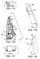
Various views of a right tower portion of the assembly of FIG. 2A are shown in FIGS. 7A-7E . The right tower portion 202 comprises a boss 700 to accept a fastener that is used to attach the print head bracket to the tower. A rounded channel 702 serves as a guide for tabs on the printer bay access door so that it may be opened, but not removed easily, to provide access to the printer and paper. The tower portion 202 further comprises guides 238 as shown in FIG. 7B to facilitate the alignment of an integrated display computer on the assembled tower and openings 230 as shown in FIG. 7D to accept screws that are used to attach the integrated display computer to the assembled tower.
Various views of a left tower portion of the assembly of FIG. 2A are shown in FIGS. 8A-8E . The left tower portion 200 comprises a boss 800 to accept a fastener that is used to attach the print head bracket to the tower. A rounded channel 802 serves as a guide for a tab on the printer bay access door so that it may be opened, but not removed easily, to provide access to the printer and paper. The tower portion 200 further comprises guides 238 as shown in FIG. 8B to facilitate the alignment of an integrated display computer on the assembled tower and openings 230 as shown in FIG. 8D to accept screws that are used to attach the integrated display computer to the assembled tower. The assembled tower then holds the integrated display computer.
Referring to FIGS. 10A-10F , various views of a printer bay access door for the assembly of FIG. 2A are shown. Referring to FIG. 10B , the printer bay access door 232 can be seen to include clips or tabs 234 for attaching the printer bay access door to the stand. The printer bay access door provides easy access to the printer so that the printer can be serviced and to the tower floor so that empty paper spools may be removed and new rolls of paper installed. The clips or tabs 232 align with rounded channels in the right and left towers so that the printer bay access door may be opened, but not removed, easily. Pivot points on the clips or tabs 232 allow the door to lay flat when opened but not detached completely. A handle 1000 in the door makes it easy to lift the door and guide it through the channels so that it lays flat and the printer or paper in the tower is easily accessed.
The enclosed peripherals provide extra functionality for the integrated display computer. As should be apparent from the figures, the tower and stand base of the present invention may house various peripherals to increase the features and functionality of the integrated display unit. Although the present invention has been explained in accordance with an example embodiment of the present invention wherein a printer is enclosed in a tower housing unit and a CD-ROM or DVD drive and USB port are enclosed in a stand base housing unit, the tower and stand base may be modified to accommodate other types of peripherals such as magnetic card readers and bar code scanners. The stand further accommodates various sizes of integrated display computers which may be attached in a landscape mode or a portrait mode. The modularity of the stand and integrated display computer which attaches to the stand allows the components to be configured in many different ways and therefore, adapted for many different uses.
In an example embodiment of the present invention, the peripherals that are contained in the tower and stand housing units are peripherals that pass FCC testing (EMI) and UL standards as stand-alone peripherals. Many personal computer USB peripherals that could be contained in the stand are stand-alone peripherals that meet such requirements. A ground path through housing unit and associated metal bracketry provides static discharge so that once attached, the stand peripheral housing unit and integrated display computer, which also meets FCC (EMI) and UL requirements, form a single unit that meets the applicable requirements.
The ability to incorporate various peripherals into a stand for an integrated display computer allows the complete unit to be configured for many applications. Such applications include use in retail stores, advertising and informational promotions, schools, libraries, and hospitals. The completed units are also suitable for use in many different settings including high-traffic settings. The peripherals are well-protected and securely incorporated into the unit. Therefore, they are unlikely to be disturbed or detached during normal operation. Furthermore, the completed unit may be attached to a surface and optionally locked to a permanent object using a cable lock. The units, therefore, are unlikely to be removed from their locations. Finally, the stand may be adapted for integrated display computers of many sizes and different orientations. Any limitations on size may be dictated by the size of actual peripheral device rather than the other components comprising the housing of the peripherals for the stand.
Integrated display computers with integrated peripherals and a stand with integrated peripherals according to the present invention provide substantial functionality in an attractive package. While example embodiments of the invention have been illustrated and described, various modifications and combinations can be made without departing from the spirit and scope of the invention. Many types of peripheral devices may be integrated into a stand according to the apparatus and method of the present invention and still fall within the scope of the present invention. The configuration of a stand according to the present invention may be varied in many ways and still fall within the scope of the present invention. Modifications, combinations, and equivalents to the apparatus and method of the present invention are intended to be covered and claimed.
Claims (14)
1. A stand for housing peripheral devices for an integrated display computer comprising:
(a) a base board comprising circuitry for controlling a peripheral device and at least one internal port for receiving an internal connector to a processor on said integrated display computer to support interactions between said processor of said integrated display computer and said peripheral;
(b) a stand base for housing said base board, wherein said stand base comprises:
(i) attachment means for accepting fasteners for attaching said base board to said stand base;
(ii) external connector accommodation means for allowing external connectors to be connected to said base board in said stand base;
(c) a stand tower for holding said integrated display computer wherein said stand tower comprises:
(i) attachment means for attaching said integrated display computer to said stand tower;
(ii) a compartment for accommodating said internal connector between said processor of said integrated display computer and said base board
(d) wherein said stand base and said stand tower are coupled to form a complete stand for housing said peripheral device and for holding said integrated display computer attached to said stand tower;
wherein said stand tower is adapted to house a second peripheral device; and wherein said second peripheral device is a printer.
2. The stand of claim 1 wherein said stand base is adapted to house a peripheral device selected from the group consisting of USB ports, digital media card readers, bar code scanners, magnetic card readers, CD-ROM drives, and DVD drives.
3. The stand of claim 1 further comprising at least one peripheral device in said stand base.
4. The stand of claim 1 wherein said external connector accommodation means for allowing external connectors to be connected to said base board in said stand base is a base door.
5. The stand of claim 4 further comprising an aperture formed when said base door is installed in said stand wherein said aperture allows external connectors to be connected to said base board.
6. The stand of claim 4 wherein said base door comprises a cutout for allowing external connectors to be attached to said base board.
7. The stand of claim 1 wherein said integrated computer display is a fanless integrated display computer.
8. A stand for housing peripheral devices for an integrated display computer comprising:
(a) a stand base for housing a base board, wherein said stand base comprises:
(i) attachment means for accepting fasteners for attaching said base board to said stand base;
(ii) external connector accommodation means for allowing external connectors to be connected to said base board in said stand base; and
(iii) wherein said base board comprises at least one internal port for receiving an internal connector to a processor on said integrated display computer to support interactions between said processor of said integrated display computer and a peripheral device;
(b) a stand tower for housing said peripheral device, wherein said stand tower comprises a right tower portion and a left tower portion for holding said peripheral device and accommodating said internal connector between said processor of said integrated display computer and said base board and comprises attachment means for attaching said integrated computer display to said stand tower;
(e) wherein said stand base and said stand tower are coupled to form a complete stand for housing said peripheral device such that said internal connector connects to said base board in said stand base and to said processor of said integrated display computer, for holding said integrated computer display attached to said stand tower, and for accommodating cables attached to said base board;
wherein said stand base is adapted to house a second peripheral device; and wherein said stand tower is adapted to house a printer.
9. The stand of claim 8 wherein said second peripheral device is selected from the group consisting of USB ports, digital media card readers, bar code scanners, magnetic card readers, CD-ROM drives, and DVD drives.
10. The stand of claim 8 further comprising at least one peripheral device in said stand tower.
11. The stand of claim 8 wherein said cable accommodation means for allowing external connectors to be attached to said base board in said stand base is a base door.
12. The stand of claim 11 further comprising an aperture formed when said base door is installed in said stand for allowing external connectors to be attached to said base board.
13. The stand of claim 11 wherein said base door comprises a cutout for allowing external connectors to be attached to said base board.
14. The stand of claim 8 wherein said integrated computer display is a fanless integrated display computer.
Priority Applications (1)
| Application Number | Priority Date | Filing Date | Title |
|---|---|---|---|
| US11/267,490 US7433185B1 (en) | 2004-09-10 | 2005-11-04 | Integrated display computer stand with integrated peripherals |
Applications Claiming Priority (3)
| Application Number | Priority Date | Filing Date | Title |
|---|---|---|---|
| US10/937,976 US7072179B1 (en) | 2004-09-10 | 2004-09-10 | Fanless computer with integrated display |
| US11/131,052 US7397659B1 (en) | 2004-09-10 | 2005-05-17 | Integrated display computer with peripherals |
| US11/267,490 US7433185B1 (en) | 2004-09-10 | 2005-11-04 | Integrated display computer stand with integrated peripherals |
Related Parent Applications (1)
| Application Number | Title | Priority Date | Filing Date |
|---|---|---|---|
| US11/131,052 Continuation-In-Part US7397659B1 (en) | 2004-09-10 | 2005-05-17 | Integrated display computer with peripherals |
Publications (1)
| Publication Number | Publication Date |
|---|---|
| US7433185B1 true US7433185B1 (en) | 2008-10-07 |
Family
ID=39797307
Family Applications (1)
| Application Number | Title | Priority Date | Filing Date |
|---|---|---|---|
| US11/267,490 Expired - Fee Related US7433185B1 (en) | 2004-09-10 | 2005-11-04 | Integrated display computer stand with integrated peripherals |
Country Status (1)
| Country | Link |
|---|---|
| US (1) | US7433185B1 (en) |
Cited By (17)
| Publication number | Priority date | Publication date | Assignee | Title |
|---|---|---|---|---|
| US20080022017A1 (en) * | 2006-07-07 | 2008-01-24 | Logic Controls, Inc. | Hybrid industrial networked computer system |
| US20090159542A1 (en) * | 2005-11-04 | 2009-06-25 | Nec Personal Products, Ltd. | Electronic Equipment and Shelf Member |
| US20110069445A1 (en) * | 2008-05-19 | 2011-03-24 | Edgar Diego Haren | Notebook Computer Docking Stations |
| US20110216493A1 (en) * | 2010-03-05 | 2011-09-08 | Hong Fu Jin Precision Industry (Shenzhen) Co., Ltd. | All-in-one computer |
| US20130094147A1 (en) * | 2011-10-14 | 2013-04-18 | Lg Electronics Inc. | Stand for display device and display device including the same |
| GB2524593A (en) * | 2014-03-27 | 2015-09-30 | Powa Technologies Ltd | Point of sale system and scanner |
| US20150313032A1 (en) * | 2014-04-28 | 2015-10-29 | Fu Tai Hua Industry (Shenzhen) Co., Ltd. | Support and display device using the same |
| US9298213B2 (en) | 2013-02-25 | 2016-03-29 | Dell Products Lp | Transforming modular display systems and methods of using same |
| US20170168973A1 (en) * | 2014-07-28 | 2017-06-15 | Hewlett-Packard Development Company, L.P. | Connecting a peripheral device |
| USD810816S1 (en) * | 2016-10-28 | 2018-02-20 | Square, Inc. | Electronic device |
| USD811472S1 (en) * | 2016-10-28 | 2018-02-27 | Square, Inc. | Electronic device |
| USD812130S1 (en) | 2016-10-28 | 2018-03-06 | Square, Inc. | Electronic device |
| USD835184S1 (en) * | 2016-01-12 | 2018-12-04 | Custom S.P.A. | Payment device |
| US20190025877A1 (en) * | 2017-07-19 | 2019-01-24 | Symmetry Office, LLC | Monitor stand base with integrated outlets |
| US10430783B2 (en) | 2016-10-03 | 2019-10-01 | Square, Inc. | Transmit phase detection circuit |
| US11225088B2 (en) * | 2017-07-14 | 2022-01-18 | Hewlett-Packard Development Company, L.P. | Printing device housed within stand of display |
| US11822383B2 (en) * | 2020-09-30 | 2023-11-21 | Lenovo (Beijing) Limited | Electronic apparatus |
Citations (47)
| Publication number | Priority date | Publication date | Assignee | Title |
|---|---|---|---|---|
| US4723195A (en) * | 1985-04-03 | 1988-02-02 | Rdi Limited Partnership | Assembly including a modular electrical circuit and connector |
| US4771365A (en) | 1987-10-30 | 1988-09-13 | Honeywell Inc. | Passive cooled electronic chassis |
| US5243493A (en) | 1992-04-29 | 1993-09-07 | Industrial Technology Research Institute | Fanless convection cooling design for personal computers |
| USD354949S (en) * | 1993-05-21 | 1995-01-31 | Li-Ho Yao | Personal computer assembly |
| US5683070A (en) | 1995-12-12 | 1997-11-04 | Seed; Paul | Means for attaching accessories to video display terminal |
| US5729431A (en) | 1995-03-24 | 1998-03-17 | Packard Bell Nec | Heat sink for a portable personal computer |
| US5742690A (en) | 1994-05-18 | 1998-04-21 | International Business Machine Corp. | Personal multimedia speaker system |
| US5761071A (en) | 1996-07-27 | 1998-06-02 | Lexitech, Inc. | Browser kiosk system |
| US5769374A (en) | 1996-05-17 | 1998-06-23 | Compaq Computer Corporation | Apparatus for mounting a computer peripheral device at selectively variable locations on a dislay monitor |
| US5781708A (en) | 1994-09-13 | 1998-07-14 | Intermec Technology, Inc. | Integral bar code printer and reader system and method of operation |
| US5826267A (en) | 1996-03-20 | 1998-10-20 | Mcmillan; James Michael | Web information kiosk |
| US5978225A (en) * | 1998-04-30 | 1999-11-02 | Ncr Corporation | Apparatus and method for dissipating heat from a core module assembly of a retail terminal |
| US5978211A (en) | 1996-11-06 | 1999-11-02 | Samsung Electronics Co., Ltd. | Stand structure for flat-panel display device with interface and speaker |
| US6032918A (en) | 1996-11-03 | 2000-03-07 | Samsung Electronics Co., Ltd. | Multi-functional device for a display device |
| US6042007A (en) | 1998-10-16 | 2000-03-28 | Ncr Corporation | Self-service computer assembly with integrated receipt printer |
| US6052279A (en) | 1996-12-05 | 2000-04-18 | Intermec Ip Corp. | Customizable hand-held computer |
| US6078848A (en) | 1996-07-27 | 2000-06-20 | Lexitech, Inc. | Browser kiosk system |
| US6081422A (en) | 1997-08-19 | 2000-06-27 | Compaq Computer Corporation | Universal mount for computer peripheral device |
| US6086173A (en) | 1997-01-17 | 2000-07-11 | International Computers Limited | Computer kiosk |
| USD428411S (en) * | 1999-10-05 | 2000-07-18 | Gateway, Inc. | Integrated desktop personal computer with modular LCD display |
| US6178087B1 (en) | 1997-10-13 | 2001-01-23 | Samsung Electronics Co. Ltd. | Multimedia apparatus using a portable computer |
| US6181554B1 (en) | 1998-10-08 | 2001-01-30 | International Business Machines Corporation | Portable computer riser for enhanced cooling |
| US6241149B1 (en) | 1997-03-03 | 2001-06-05 | Siemens Nixdorf Informationssysteme Aktiengesellschaft | Multifunctional modular operator unit for commercial use |
| US6275375B1 (en) | 1997-01-10 | 2001-08-14 | Samsung Electronics Co., Ltd. | Monitor stand with hub mount |
| US6290517B1 (en) | 1999-08-17 | 2001-09-18 | Gateway, Inc. | Fold out port group for portable computer |
| US20010034664A1 (en) | 2000-02-22 | 2001-10-25 | Brunson Jonathan E. | Systems and methods for performing e-commerce and communications over a network |
| US6324056B1 (en) | 1998-04-08 | 2001-11-27 | Siemens Aktiengesellschaft | Device for cooling a personal computer housed in a casing |
| US6336615B1 (en) | 1999-03-12 | 2002-01-08 | Lg Electronics, Inc. | Device for mounting speaker on display |
| US6442018B1 (en) | 1999-12-01 | 2002-08-27 | International Business Machine Corporation | Briefcase computer |
| US6502076B1 (en) | 1999-06-01 | 2002-12-31 | Ncr Corporation | System and methods for determining and displaying product promotions |
| US6507352B1 (en) * | 1998-12-23 | 2003-01-14 | Ncr Corporation | Apparatus and method for displaying a menu with an interactive retail terminal |
| US6532152B1 (en) | 1998-11-16 | 2003-03-11 | Intermec Ip Corp. | Ruggedized hand held computer |
| US20030048256A1 (en) | 2001-09-07 | 2003-03-13 | Salmon Peter C. | Computing device with roll up components |
| US20030115096A1 (en) | 2001-12-17 | 2003-06-19 | Reynolds Randy B. | Computer-controlled, remotely programmed at-shelf advertising system |
| US6590764B2 (en) | 2001-11-15 | 2003-07-08 | Hewlett-Packard Development Company, L.P. | Palmtop computer stand |
| US20030235029A1 (en) * | 2002-06-19 | 2003-12-25 | John Doherty | Tablet computing device with three-dimensional docking support |
| US6682251B1 (en) | 2000-11-09 | 2004-01-27 | Koninklijke Philips Electronics N.V. | System for snapping a periferal device to a circumferential edge of a pedestal |
| USD486486S1 (en) * | 2001-11-08 | 2004-02-10 | Apple Computer, Inc. | Display device with a moveable assembly |
| US20040184047A1 (en) | 2003-03-20 | 2004-09-23 | Silverbrook Research Pty Ltd | Printing and display device |
| US20040190238A1 (en) | 2001-03-01 | 2004-09-30 | Mds Advertising, Inc | Portable computer stand with integral communication method and apparatus |
| US6819550B2 (en) * | 2001-11-08 | 2004-11-16 | Apple Computer, Inc. | Computer controlled display device |
| US6839227B1 (en) | 1996-05-09 | 2005-01-04 | Carlos Correa | Computer monitor utility assembly |
| US6839231B2 (en) | 2003-01-07 | 2005-01-04 | Vulcan Portals Inc. | Heat dissipation from a hand-held portable computer |
| US20050219812A1 (en) | 2004-04-01 | 2005-10-06 | Strobel Larry A | Environmental control system for personal computers |
| US7055160B1 (en) * | 2002-12-20 | 2006-05-30 | Apple Computer, Inc. | Bezel door for computer enclosure |
| US7072179B1 (en) * | 2004-09-10 | 2006-07-04 | Micro Industries Corporation | Fanless computer with integrated display |
| US20070013277A1 (en) * | 2005-07-15 | 2007-01-18 | Hon Hai Precision Industry Co., Ltd. | Cover mechanism |
-
2005
- 2005-11-04 US US11/267,490 patent/US7433185B1/en not_active Expired - Fee Related
Patent Citations (48)
| Publication number | Priority date | Publication date | Assignee | Title |
|---|---|---|---|---|
| US4723195A (en) * | 1985-04-03 | 1988-02-02 | Rdi Limited Partnership | Assembly including a modular electrical circuit and connector |
| US4771365A (en) | 1987-10-30 | 1988-09-13 | Honeywell Inc. | Passive cooled electronic chassis |
| US5243493A (en) | 1992-04-29 | 1993-09-07 | Industrial Technology Research Institute | Fanless convection cooling design for personal computers |
| USD354949S (en) * | 1993-05-21 | 1995-01-31 | Li-Ho Yao | Personal computer assembly |
| US5742690A (en) | 1994-05-18 | 1998-04-21 | International Business Machine Corp. | Personal multimedia speaker system |
| US5781708A (en) | 1994-09-13 | 1998-07-14 | Intermec Technology, Inc. | Integral bar code printer and reader system and method of operation |
| US5729431A (en) | 1995-03-24 | 1998-03-17 | Packard Bell Nec | Heat sink for a portable personal computer |
| US5683070A (en) | 1995-12-12 | 1997-11-04 | Seed; Paul | Means for attaching accessories to video display terminal |
| US5826267A (en) | 1996-03-20 | 1998-10-20 | Mcmillan; James Michael | Web information kiosk |
| US6839227B1 (en) | 1996-05-09 | 2005-01-04 | Carlos Correa | Computer monitor utility assembly |
| US5769374A (en) | 1996-05-17 | 1998-06-23 | Compaq Computer Corporation | Apparatus for mounting a computer peripheral device at selectively variable locations on a dislay monitor |
| US5761071A (en) | 1996-07-27 | 1998-06-02 | Lexitech, Inc. | Browser kiosk system |
| US6078848A (en) | 1996-07-27 | 2000-06-20 | Lexitech, Inc. | Browser kiosk system |
| US6032918A (en) | 1996-11-03 | 2000-03-07 | Samsung Electronics Co., Ltd. | Multi-functional device for a display device |
| US5978211A (en) | 1996-11-06 | 1999-11-02 | Samsung Electronics Co., Ltd. | Stand structure for flat-panel display device with interface and speaker |
| US6052279A (en) | 1996-12-05 | 2000-04-18 | Intermec Ip Corp. | Customizable hand-held computer |
| US6275375B1 (en) | 1997-01-10 | 2001-08-14 | Samsung Electronics Co., Ltd. | Monitor stand with hub mount |
| US6086173A (en) | 1997-01-17 | 2000-07-11 | International Computers Limited | Computer kiosk |
| US6241149B1 (en) | 1997-03-03 | 2001-06-05 | Siemens Nixdorf Informationssysteme Aktiengesellschaft | Multifunctional modular operator unit for commercial use |
| US6081422A (en) | 1997-08-19 | 2000-06-27 | Compaq Computer Corporation | Universal mount for computer peripheral device |
| US6178087B1 (en) | 1997-10-13 | 2001-01-23 | Samsung Electronics Co. Ltd. | Multimedia apparatus using a portable computer |
| US6324056B1 (en) | 1998-04-08 | 2001-11-27 | Siemens Aktiengesellschaft | Device for cooling a personal computer housed in a casing |
| US5978225A (en) * | 1998-04-30 | 1999-11-02 | Ncr Corporation | Apparatus and method for dissipating heat from a core module assembly of a retail terminal |
| US6181554B1 (en) | 1998-10-08 | 2001-01-30 | International Business Machines Corporation | Portable computer riser for enhanced cooling |
| US6042007A (en) | 1998-10-16 | 2000-03-28 | Ncr Corporation | Self-service computer assembly with integrated receipt printer |
| US6532152B1 (en) | 1998-11-16 | 2003-03-11 | Intermec Ip Corp. | Ruggedized hand held computer |
| US6507352B1 (en) * | 1998-12-23 | 2003-01-14 | Ncr Corporation | Apparatus and method for displaying a menu with an interactive retail terminal |
| US6336615B1 (en) | 1999-03-12 | 2002-01-08 | Lg Electronics, Inc. | Device for mounting speaker on display |
| US6502076B1 (en) | 1999-06-01 | 2002-12-31 | Ncr Corporation | System and methods for determining and displaying product promotions |
| US6290517B1 (en) | 1999-08-17 | 2001-09-18 | Gateway, Inc. | Fold out port group for portable computer |
| USD428411S (en) * | 1999-10-05 | 2000-07-18 | Gateway, Inc. | Integrated desktop personal computer with modular LCD display |
| US6442018B1 (en) | 1999-12-01 | 2002-08-27 | International Business Machine Corporation | Briefcase computer |
| US20010034664A1 (en) | 2000-02-22 | 2001-10-25 | Brunson Jonathan E. | Systems and methods for performing e-commerce and communications over a network |
| US6682251B1 (en) | 2000-11-09 | 2004-01-27 | Koninklijke Philips Electronics N.V. | System for snapping a periferal device to a circumferential edge of a pedestal |
| US20040190238A1 (en) | 2001-03-01 | 2004-09-30 | Mds Advertising, Inc | Portable computer stand with integral communication method and apparatus |
| US20030048256A1 (en) | 2001-09-07 | 2003-03-13 | Salmon Peter C. | Computing device with roll up components |
| USD486486S1 (en) * | 2001-11-08 | 2004-02-10 | Apple Computer, Inc. | Display device with a moveable assembly |
| US7136280B2 (en) * | 2001-11-08 | 2006-11-14 | Apple Computer, Inc. | Computer controlled display device |
| US6819550B2 (en) * | 2001-11-08 | 2004-11-16 | Apple Computer, Inc. | Computer controlled display device |
| US6590764B2 (en) | 2001-11-15 | 2003-07-08 | Hewlett-Packard Development Company, L.P. | Palmtop computer stand |
| US20030115096A1 (en) | 2001-12-17 | 2003-06-19 | Reynolds Randy B. | Computer-controlled, remotely programmed at-shelf advertising system |
| US20030235029A1 (en) * | 2002-06-19 | 2003-12-25 | John Doherty | Tablet computing device with three-dimensional docking support |
| US7055160B1 (en) * | 2002-12-20 | 2006-05-30 | Apple Computer, Inc. | Bezel door for computer enclosure |
| US6839231B2 (en) | 2003-01-07 | 2005-01-04 | Vulcan Portals Inc. | Heat dissipation from a hand-held portable computer |
| US20040184047A1 (en) | 2003-03-20 | 2004-09-23 | Silverbrook Research Pty Ltd | Printing and display device |
| US20050219812A1 (en) | 2004-04-01 | 2005-10-06 | Strobel Larry A | Environmental control system for personal computers |
| US7072179B1 (en) * | 2004-09-10 | 2006-07-04 | Micro Industries Corporation | Fanless computer with integrated display |
| US20070013277A1 (en) * | 2005-07-15 | 2007-01-18 | Hon Hai Precision Industry Co., Ltd. | Cover mechanism |
Non-Patent Citations (7)
| Title |
|---|
| "Hush Debuts Fanless Pentium 4PC, Sleek-looking desktop keeps its cool quietly.," PC World, Sumner Lemon, IDG News Service, Sep. 23, 2003. http://www.pcworld.com/resource/printable/article/9,aid,112608,00.asp. |
| "Little PC's-Fanless," Stealth Computer Corporation, http://www.stealthcomputer.com/littlepc<SUB>-</SUB>fanless.htm. |
| "Management Software for Interactive Terminals-Kiosks-Media Displays," Kudos-Products, 2 pages from website, http://www.kudosdigital.com/products. |
| "Microspace(R)-PC from Digital-Logic-the smallest and fanless computer for rough environmental conditions," Digital-Logic AG-Press Release, Nov. 2002, http://digitallogic.presseagentur.com/pr-infos/digitallogic/en/PR11-02.htm. |
| Copient Technologies, Products and Services, web page, 2 pages, dated Mar. 9, 2005, from http://web.archive.org/web/20030806105437/www.copienttech.com/pro. |
| Copient Technologies, web page, 1 page, dated Mar. 9, 2005, from http://web.archive.org/web/20030724224421/http://www.copienttech.com. |
| TouchPoint Solutions, Inc.-Catapult Software, Catapult(TM), 2 pages from website, http://www.touchpointsolutions.com/site/technology/discover<SUB>-</SUB>catapult.html. |
Cited By (27)
| Publication number | Priority date | Publication date | Assignee | Title |
|---|---|---|---|---|
| US20090159542A1 (en) * | 2005-11-04 | 2009-06-25 | Nec Personal Products, Ltd. | Electronic Equipment and Shelf Member |
| US8009414B2 (en) * | 2005-11-04 | 2011-08-30 | Nec Personal Products, Ltd. | Electronic equipment and shelf member |
| US7984195B2 (en) * | 2006-07-07 | 2011-07-19 | Logic Controls, Inc. | Hybrid industrial networked computer system |
| US20080022017A1 (en) * | 2006-07-07 | 2008-01-24 | Logic Controls, Inc. | Hybrid industrial networked computer system |
| US8634188B2 (en) * | 2008-05-19 | 2014-01-21 | Hewlett-Packard Development Company, L.P. | Notebook computer docking stations |
| US20110069445A1 (en) * | 2008-05-19 | 2011-03-24 | Edgar Diego Haren | Notebook Computer Docking Stations |
| US20110216493A1 (en) * | 2010-03-05 | 2011-09-08 | Hong Fu Jin Precision Industry (Shenzhen) Co., Ltd. | All-in-one computer |
| US8248780B2 (en) * | 2010-03-05 | 2012-08-21 | Hong Fu Jin Precision Industry (Shenzhen) Co., Ltd. | All-in-one computer |
| US9291298B2 (en) * | 2011-10-14 | 2016-03-22 | Lg Electronics Inc. | Stand for display device and display device including the same |
| US20130094147A1 (en) * | 2011-10-14 | 2013-04-18 | Lg Electronics Inc. | Stand for display device and display device including the same |
| US9298213B2 (en) | 2013-02-25 | 2016-03-29 | Dell Products Lp | Transforming modular display systems and methods of using same |
| GB2524593A (en) * | 2014-03-27 | 2015-09-30 | Powa Technologies Ltd | Point of sale system and scanner |
| WO2015145179A1 (en) * | 2014-03-27 | 2015-10-01 | Powa Technologies Limited | Point of sale system and scanner |
| US20150313032A1 (en) * | 2014-04-28 | 2015-10-29 | Fu Tai Hua Industry (Shenzhen) Co., Ltd. | Support and display device using the same |
| US9423055B2 (en) * | 2014-04-28 | 2016-08-23 | Fu Tai Hua Industry (Shenzhen) Co., Ltd. | Support and display device using the same |
| US10185686B2 (en) * | 2014-07-28 | 2019-01-22 | Hewlett-Packard Development Company, L.P. | Connecting a peripheral device |
| US20170168973A1 (en) * | 2014-07-28 | 2017-06-15 | Hewlett-Packard Development Company, L.P. | Connecting a peripheral device |
| USD835184S1 (en) * | 2016-01-12 | 2018-12-04 | Custom S.P.A. | Payment device |
| US10430783B2 (en) | 2016-10-03 | 2019-10-01 | Square, Inc. | Transmit phase detection circuit |
| USD810816S1 (en) * | 2016-10-28 | 2018-02-20 | Square, Inc. | Electronic device |
| USD811472S1 (en) * | 2016-10-28 | 2018-02-27 | Square, Inc. | Electronic device |
| USD812130S1 (en) | 2016-10-28 | 2018-03-06 | Square, Inc. | Electronic device |
| USD831107S1 (en) | 2016-10-28 | 2018-10-16 | Square, Inc. | Electronic device |
| USD854612S1 (en) | 2016-10-28 | 2019-07-23 | Square, Inc. | Electronic device |
| US11225088B2 (en) * | 2017-07-14 | 2022-01-18 | Hewlett-Packard Development Company, L.P. | Printing device housed within stand of display |
| US20190025877A1 (en) * | 2017-07-19 | 2019-01-24 | Symmetry Office, LLC | Monitor stand base with integrated outlets |
| US11822383B2 (en) * | 2020-09-30 | 2023-11-21 | Lenovo (Beijing) Limited | Electronic apparatus |
Similar Documents
| Publication | Publication Date | Title |
|---|---|---|
| US7433185B1 (en) | Integrated display computer stand with integrated peripherals | |
| US6778381B1 (en) | Retractable display module | |
| US6407933B1 (en) | Cable management system for use with rack mounted devices | |
| US6556438B1 (en) | Dense packaging and cooling system for use with a server or other processor-based device | |
| US5187645A (en) | Portable computer with docking connector for peripheral devices | |
| US8365868B2 (en) | Kiosk | |
| US7106581B2 (en) | Modular logic board chassis for a desktop computer | |
| US5828547A (en) | Computer case having slidably insertable drive housing with U-shaped mounting bracket having inwardly projecting pins on two opposed legs | |
| US6603661B2 (en) | Universal fan cage for hot-pluggable fans | |
| US7826213B2 (en) | Server chassis with access flap | |
| US7312999B1 (en) | High density drive chassis assembly | |
| US6462670B1 (en) | Server system having front and rear identification | |
| US20080250179A1 (en) | Discrete Computer Processor System and Peripherals System | |
| US7072179B1 (en) | Fanless computer with integrated display | |
| EP1640930B9 (en) | Controller structure of merchandise sales data processing apparatus | |
| US7542283B1 (en) | Integrated display computer with telephone switch cradle peripheral | |
| US20070076369A1 (en) | Method of determining minimal dimension of computer and computer designed though the method | |
| US6288893B1 (en) | Desktop computer system having reduced footprint semi-mobile CPU unit | |
| TW523650B (en) | Computer with modular removeable media drive | |
| CN101098598B (en) | Rotatable component support assembly for an electronics enclosure | |
| KR100454719B1 (en) | Modular desktop computer | |
| US6477055B1 (en) | System for reducing airflow obstruction in a low profile processor-based device | |
| TWI669594B (en) | Pos apparatus | |
| US6597567B2 (en) | Corner support members for housing system | |
| US6754084B1 (en) | System for mounting PCI cards |
Legal Events
| Date | Code | Title | Description |
|---|---|---|---|
| AS | Assignment |
Owner name: MICRO INDUSTRIES CORPORATION, OHIO Free format text: ASSIGNMENT OF ASSIGNORS INTEREST;ASSIGNORS:CURRAN, MICHAEL A.;PECK, GARY A.;REEL/FRAME:017213/0177 Effective date: 20051101 |
|
| CC | Certificate of correction | ||
| FPAY | Fee payment |
Year of fee payment: 4 |
|
| REMI | Maintenance fee reminder mailed | ||
| LAPS | Lapse for failure to pay maintenance fees | ||
| STCH | Information on status: patent discontinuation |
Free format text: PATENT EXPIRED DUE TO NONPAYMENT OF MAINTENANCE FEES UNDER 37 CFR 1.362 |
|
| FP | Lapsed due to failure to pay maintenance fee |
Effective date: 20161007 |