US7437944B2 - Method and apparatus for pressure and mix ratio control - Google Patents
Method and apparatus for pressure and mix ratio control Download PDFInfo
- Publication number
- US7437944B2 US7437944B2 US11/684,888 US68488807A US7437944B2 US 7437944 B2 US7437944 B2 US 7437944B2 US 68488807 A US68488807 A US 68488807A US 7437944 B2 US7437944 B2 US 7437944B2
- Authority
- US
- United States
- Prior art keywords
- gas
- flow
- gas line
- pressure
- line
- Prior art date
- Legal status (The legal status is an assumption and is not a legal conclusion. Google has not performed a legal analysis and makes no representation as to the accuracy of the status listed.)
- Active
Links
- 238000000034 method Methods 0.000 title abstract description 26
- 238000012545 processing Methods 0.000 claims abstract description 73
- 238000011144 upstream manufacturing Methods 0.000 claims abstract description 27
- 238000005259 measurement Methods 0.000 claims description 30
- 239000004065 semiconductor Substances 0.000 claims description 25
- 239000008186 active pharmaceutical agent Substances 0.000 claims description 24
- 239000000758 substrate Substances 0.000 claims description 12
- 230000008878 coupling Effects 0.000 claims description 10
- 238000010168 coupling process Methods 0.000 claims description 10
- 238000005859 coupling reaction Methods 0.000 claims description 10
- 239000007789 gas Substances 0.000 description 171
- 239000000203 mixture Substances 0.000 description 38
- 230000008569 process Effects 0.000 description 17
- 230000001052 transient effect Effects 0.000 description 8
- 238000000231 atomic layer deposition Methods 0.000 description 4
- 230000008859 change Effects 0.000 description 4
- 238000005229 chemical vapour deposition Methods 0.000 description 4
- 238000005240 physical vapour deposition Methods 0.000 description 4
- 238000009530 blood pressure measurement Methods 0.000 description 3
- 238000004891 communication Methods 0.000 description 3
- 239000012530 fluid Substances 0.000 description 3
- 238000005086 pumping Methods 0.000 description 3
- 230000007423 decrease Effects 0.000 description 2
- 238000005530 etching Methods 0.000 description 2
- 230000007246 mechanism Effects 0.000 description 2
- 230000008901 benefit Effects 0.000 description 1
- 239000012159 carrier gas Substances 0.000 description 1
- 238000012544 monitoring process Methods 0.000 description 1
- 238000004886 process control Methods 0.000 description 1
- 238000010926 purge Methods 0.000 description 1
- 239000000376 reactant Substances 0.000 description 1
- 230000007306 turnover Effects 0.000 description 1
Images


Classifications
-
- G—PHYSICS
- G01—MEASURING; TESTING
- G01F—MEASURING VOLUME, VOLUME FLOW, MASS FLOW OR LIQUID LEVEL; METERING BY VOLUME
- G01F15/00—Details of, or accessories for, apparatus of groups G01F1/00 - G01F13/00 insofar as such details or appliances are not adapted to particular types of such apparatus
- G01F15/02—Compensating or correcting for variations in pressure, density or temperature
- G01F15/04—Compensating or correcting for variations in pressure, density or temperature of gases to be measured
- G01F15/043—Compensating or correcting for variations in pressure, density or temperature of gases to be measured using electrical means
-
- G—PHYSICS
- G05—CONTROLLING; REGULATING
- G05D—SYSTEMS FOR CONTROLLING OR REGULATING NON-ELECTRIC VARIABLES
- G05D11/00—Control of flow ratio
- G05D11/02—Controlling ratio of two or more flows of fluid or fluent material
- G05D11/13—Controlling ratio of two or more flows of fluid or fluent material characterised by the use of electric means
- G05D11/131—Controlling ratio of two or more flows of fluid or fluent material characterised by the use of electric means by measuring the values related to the quantity of the individual components
- G05D11/132—Controlling ratio of two or more flows of fluid or fluent material characterised by the use of electric means by measuring the values related to the quantity of the individual components by controlling the flow of the individual components
-
- G—PHYSICS
- G05—CONTROLLING; REGULATING
- G05D—SYSTEMS FOR CONTROLLING OR REGULATING NON-ELECTRIC VARIABLES
- G05D16/00—Control of fluid pressure
- G05D16/20—Control of fluid pressure characterised by the use of electric means
- G05D16/2006—Control of fluid pressure characterised by the use of electric means with direct action of electric energy on controlling means
- G05D16/2013—Control of fluid pressure characterised by the use of electric means with direct action of electric energy on controlling means using throttling means as controlling means
- G05D16/2026—Control of fluid pressure characterised by the use of electric means with direct action of electric energy on controlling means using throttling means as controlling means with a plurality of throttling means
- G05D16/2046—Control of fluid pressure characterised by the use of electric means with direct action of electric energy on controlling means using throttling means as controlling means with a plurality of throttling means the plurality of throttling means being arranged for the control of a single pressure from a plurality of converging pressures
Definitions
- Embodiments of the present invention generally relate to a method and apparatus for controlling pressure and mix ratio in gas delivery. More specifically, embodiments of the invention generally relate to a method and apparatus for controlling pressure and mix ratio of gas provided to a semiconductor processing chamber.
- Processing gases are widely used in semiconductor processing. Processing gases may be provided as reactant gas, carrier gas or purge gas to process a front side of a substrate. Gases may also be provided between a substrate and a substrate support in a semiconductor processing chamber to maintain a precise and uniform of substrate temperature.
- Pressure and mix ratio of the processing gas are important process control attributes to many semiconductor processes. Pressure and mix ratio are conventionally controlled separately.
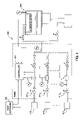
- FIG. 1 depicts a simplified schematic of a conventional semiconductor processing chamber 100 having a gas delivery system 120 shown providing processing gas to a processing volume 103 in the processing chamber 100 .
- the processing volume 103 defined by a chamber body 101 is configured to process a substrate 104 therein.
- the processing volume 103 is in selective fluid communication with a vacuum pump 105 via a throttle valve 107 .
- the vacuum pump 105 maybe connected to a rough pump 106 .
- the processing chamber 100 may be configured to perform chemical vapor deposition (CVD), physical vapor deposition (PVD), atomic layer deposition (ALD), etching or other processing technique.
- CVD chemical vapor deposition
- PVD physical vapor deposition
- ALD atomic layer deposition
- etching or other processing technique.
- the gas delivery system 120 is configured to mix and deliver two or more gases to the processing chamber 100 via a gas line 131 .
- a shut off valve 129 is positioned on the gas line 131 .
- the gas delivery system 120 includes a first gas supply and a second gas supply line parallel to one another.
- the first gas supply line include a gas source 121 connected to the gas line 131 via a shut off valve 123 and a control valve 127 .
- the second gas supply line includes a gas source 122 connected to the gas line 131 via a shut off valve 124 and a control valve 127 .
- gases from the gas sources 121 , 122 come through control valves 127 , 128 respectively, are mixed together in the gas line 131 and are delivered to the processing volume 103 .
- the ratio of each gas in the gas mixture is controlled by a ratio controller 130 .
- the ratio controller 130 adjusts the control valves 127 , 128 to obtain desired mix ratio in the gas delivered to the processing chamber 100 .
- Chamber pressure is controlled separately from the mix ratio.
- a pressure control unit 110 may be used to obtain a desired pressure the chamber.
- the pressure control unit 110 may adjust the chamber pressure by adjusting the throttle valve 107 according to feedback from a chamber pressure gauge 109 .
- Chamber pressure is a result of flow rate from the gas line 131 and the status of the throttle valve 107 .
- the conventional chamber pressure and mix ratio control described above has a relatively slow responding time to achieve a target chamber pressure and/or a target mix ratio. For example, when adjusting chamber pressure from a lower pressure to a higher pressure, the pressure control unit 108 decreases opening of the throttle valve 107 and wait for more gas flowing in from the gas line 131 to increases the chamber pressure. On the one hand, it may take a few seconds before the chamber pressure reaches the desired value, which is long relative to a typical semiconductor processing step. On the other hand, it takes relatively long time to adjust a mix ratio in the process volume 103 too.
- the mix ratio controller 130 can adjust the control valves 125 , 126 to change the flow rates supplied to the gas line 131 .
- existing gas in the processing volume 103 will have to be pumped out before mix ratio reaches desired valve in the processing volume 103 .
- a method and apparatus for gas control is provided for rapid adjustment of mix ratio supplied to a processing chamber and for adjustment of chamber pressure.
- One embodiment provides an apparatus for gas control comprising a first flow sensor having an inlet connected to a first gas line adapted for coupling a gas supply, a first control valve coupled to an outlet of the first flow sensor, a second flow sensor having an inlet connected to a second gas line adapted for coupling a gas supply, a second control valve coupled to an outlet of the second flow sensor, and a third gas line having an inlet coupled to outlets of both the first control valve and the second control valve.
- Another embodiment provides an apparatus for gas control comprising a first gas supply line that comprises a first flow sensor, a first control valve, a first gas line coupled to an inlet of the first flow sensor, and a second gas line coupled to an outlet of the first flow sensor and an inlet of the first control valve, a second gas supply line that comprises a second flow sensor, a second control valve, a third gas line coupled to an inlet of the second flow sensor, and a fourth gas line coupled to an outlet of the second flow sensor and an inlet of the second control valve, and an output line coupled to an outlet of the first control valve and an outlet of the second control valve.
- Yet another embodiment provides a gas delivery system comprising a first gas line configured for coupling to a first gas supply, a first flow sensor having an inlet connected to the first gas line, a first control valve coupled to the first flow sensor, a second gas line configured for coupling to a second gas supply, a second flow sensor having an inlet connected to the second gas line, a second control valve coupled to the second flow sensor, a third gas line having an upstream end connected to outlets of the first and second control valves and a downstream end configured for coupling to a processing chamber, and a controller configured to control a ratio of a gas flow in the first gas line and a gas flow in the second gas line, wherein the controller receives measurement form the first and second flow sensors and sends control signals to the first and second control valves.
- FIG. 1 is a simplified schematic of a conventional semiconductor processing chamber and gas delivery system.
- FIG. 2 schematically illustrates a gas delivery system in accordance with one embodiment of the present invention coupled to an exemplary semiconductor processing chamber.
- FIG. 3 schematically illustrates a gas delivery system in accordance with one embodiment of the present invention.
- the gas delivery system has a pressure insensitive flow sensing mechanism and is coupled to an exemplary semiconductor processing chamber.
- FIG. 4 schematically illustrates a gas delivery system in accordance with one embodiment of the present invention.
- the gas delivery system has a plurality of gas supply lines and is coupled to an exemplary semiconductor processing chamber.
- the present invention provides apparatus and method for controlling mix ratio of gas supplied to a processing chamber integrated with chamber pressure.
- an integrated controller is used to adjust mix ratio and chamber pressure simultaneously.
- One embodiment provides a flow device for controlling a chamber pressure while simultaneously controlling mix ratio of gases.
- the mix ratio and chamber pressure may be adjusted using a flow sensor and a control valve disposed in each gas supply line.
- the flow sensor used in each gas supply line is insensitive to upstream pressure perturbations.
- FIG. 2 schematically illustrates a gas delivery system 220 in accordance with one embodiment of the present invention coupled to an exemplary semiconductor processing chamber 200 .
- the gas delivery system 220 is configured to provide processing gas to a processing volume 203 in the processing chamber 200 with desired mix ratio and chamber pressure.
- the processing volume 203 is defined by a chamber body 201 and is configured to process one or more substrate 204 therein.
- the processing volume 203 is in selective fluid communication with a vacuum pump 205 via a restriction 208 and/or a restriction 207 .
- the restrictions 207 , 208 may be throttle valves or dump valves configured to quickly decrease or increase conductance between the processing volume 203 and the vacuum pump 205 .
- the vacuum pump 205 may be connected to a rough pump 206 .
- the processing chamber 200 may be configured to perform chemical vapor deposition (CVD), physical vapor deposition (PVD), atomic layer deposition (ALD), etching or other processing technique.
- CVD chemical vapor deposition
- PVD physical vapor deposition
- ALD atomic layer deposition
- etching or other processing technique.
- Process gas delivery systems, pumping systems and the like for controlling processes performed within the processing chamber are well-known and have been omitted for the sake of brevity.
- the gas delivery system 220 is configured to mix and deliver two or more gases to the processing chamber 200 .
- a host software 229 is connected the gas delivery system 220 to provide mix ratio and chamber pressure instructions.
- the host software 229 may receive one or more feedback signals from the gas delivery system 220 for monitoring system performance or for a closed loop control.
- the host software 229 may additionally control processes performed in the processing chamber 200 .
- the gas delivery system 220 comprises a first gas supply line 247 and a second gas supply line 248 .
- the first gas supply line 247 and the second gas supply line 248 are in parallel connection.
- the first gas supply line 247 is connected to a gas source 221 and second gas supply line 248 is connected to a second gas source 222 .
- the gas delivery system 220 comprises an output gas line 237 configured to output a mixture of gases comprising gases from the first and second gas sources 221 , 222 .
- the output gas line 237 may be connected to an inlet line 231 of the process chamber 200 through a shut off valve 235 .
- the output gas line 237 may connect to a bypass line 232 via a shut off valve 236 .
- the bypass line 232 may be connected directly to the rough pump 206 or the chamber body 201 then to the vacuum pump 205 .
- the shut off valves 235 , 236 determine whether the gas mixture from the gas delivery system 220 goes to the processing chamber 200 or to be bypassed. In one embodiment, the shut off valves 235 , 236 are interlocked. In one embodiment, the shutoff valves 235 , 236 may be hybrid valves with pneumatic and manual actuators.
- the gas delivery system 220 comprises a controller 230 , and two or more gas parallel gas supply lines connected together at down stream end. As shown in FIG. 2 , the gas supply line 247 and the gas supply line 248 are parallel to another, each configured to carry a gas from a gas source connected upstream. The gas supply line 247 and the gas supply line 248 joint together with the output 237 .
- the gas supply line 247 comprises a flow sensor 225 and a control valve 227 .
- An inlet of the flow sensor 225 is coupled to a first intermediate line 241 , which may be connected to the gas source 221 via shut off valve 223 .
- a second intermediate line 243 is coupled to an outlet of the flow sensor 225 and an inlet of the control valve 227 .
- An outlet of the control valve 227 is coupled to a third intermediate line 245 , which is connected to the output gas line 237 .
- the flow sensor 225 provides a metric indicative of flow passing into the gas delivery system 220 from the gas source 221 .
- the control valve 227 modulates the flow rate passing into the gas delivery system 220 from the gas source 221 .
- the gas supply line 247 may comprises a shutoff valve 233 in the third intermediate line 245 .
- the gas supply line 248 comprises a flow sensor 226 and a control valve 228 .
- An inlet of the flow sensor 226 is coupled to a first intermediate line 242 , which may be connected to the gas source 222 via a shut off valve 224 .
- a second intermediate line 244 is coupled to an outlet of the flow sensor 226 and an inlet of the control valve 228 .
- An outlet of the control valve 228 is coupled to a third intermediate line 246 , which joints the third intermediate line 245 of the gas supply line 247 and is coupled to the output gas line 237 .
- the flow sensor 226 provides a metric indicative of flow passing into the gas delivery system 220 from the gas source 222 .
- the control valve 228 modulates the flow rate passing into the gas delivery system 220 from the gas source 222 .
- the gas supply line 248 may comprises a shutoff valve 234 in the third intermediate line 246 .
- the gas delivery system 220 comprises a controller 230 .
- the controller 230 receives instructions from the host software 229 , or from a system controller.
- the controller 230 receives measurement signals from the flow sensors 225 , 226 , and from a pressure sensor 209 configured to measure chamber pressure in the processing volume 203 .
- the controller 230 provides control signals to the control valves 227 , 228 according to instructions from the host software 229 and measurements from the sensors.
- the controller 230 may provide control signals to the restriction 207 and/or the restriction 208 to assist chamber pressure and/or mix ratio control.
- the host software 229 may send control signals to the restriction 207 and/or the restriction 208 during process to assist chamber pressure and/or mix ratio control.
- the pressure sensor 209 is configured to measure the actual chamber pressure in the processing volume 203 .
- a cavity 257 in fluid communication with the inlet line 231 may be present between the processing volume 203 and the outline line 231 .
- the actual chamber pressure is likely to be different from the pressure in the inlet line 231 because there usually exists a restriction, such as a shower head 202 , between the processing volume 203 and the inlet line 231 or the cavity 257 .
- the shutoff valves 235 , 236 may be pneumatic valves necessary to allow quick dump of line pressure upstream of the chamber 200 when changing pressure set point or when changing mix ratio.
- the control valves 235 , 236 may be interlocked to prevent pumping chamber gas into the gas delivery system 220 and to prevent impacts to chamber pressure.
- the shutoff valves 223 , 224 may be pneumatic valves necessary to isolate gases from different gas sources.
- gases from the gas sources 221 , 222 come through the control valves 227 , 228 respectively, are mixed together in the output gas line 237 and are delivered to the processing volume 203 , or bypassed through the bypass line 232 .
- the ratio of each gas in the gas mixture and the chamber pressure are controlled by the controller 230 .
- the controller 230 adjusts the control valves 227 , 228 according to measurement from the flow sensors 225 , 226 to obtain desired mix ratio in the gas delivered to the processing chamber 200 and desired chamber pressure.
- the controller 230 adjusts the control valves 227 , 228 and restrictions in the processing chamber 200 , such as the restrictions 207 , 208 , according to measurement from the flow sensors 225 , 226 to the processing chamber 200 .
- the controller 230 may hasten the change in mix ratio and/or adjust the rate of turn over in the process chamber by adjusting the restrictions in the processing chamber 200 , especially when additional parameters impact the process.
- the gas delivery system 220 is configured to control mix ratio of gases chamber pressure, or actual flow into the chamber. Conventional control algorithms may be used to achieve control tasks.
- the gas delivery system 220 may be set to one or more transient states before settles in a steady state to obtain speedy adjustment to mix ratio and/or chamber pressure. For example, when adjusting the chamber pressure from a higher pressure to a lower pressure, the controller 230 may close both control valves 227 , 228 in a transient state to allow the chamber pressure to drop. While the control valves 227 , 228 are then set to positions that maintain the lower pressure in the processing volume 203 .
- FIG. 3 schematically illustrates a gas delivery system 320 in accordance with one embodiment of the present invention.
- the gas delivery system 320 has a pressure insensitive flow sensing mechanism and is coupled to an exemplary semiconductor processing chamber 200 .
- Identical reference numerals have been used for similar elements in FIGS. 2 and 3 for simplicity.
- the gas delivery system 320 comprises gas supply lines 253 , 254 .
- the gas supply lines 253 , 254 are similar to the gas supply lines 247 , 248 except that the gas supply lines 253 , 254 comprise upstream pressure sensors 251 , 252 coupled to the intermediate lines 241 , 242 .
- the pressure sensors 251 , 252 are configured to sense a metric indicative of pressure within the intermediate lines 241 , 242 .
- the pressure sensors 251 , 252 are used to ensure that the flow sensors 225 , 226 are insensitive to upstream pressure perturbations.
- measurements from the flow sensors 225 , 226 may be compensated by a function of dP U /dt, wherein P U is a pressure measurement from the pressure sensors 251 , 252 .
- an intermediate pressure sensor 255 , 256 may be used to measure metrics indicative of pressure in the second intermediate lines 243 , 244 , and the actual flow may be calculated using the following equation:
- F A F S + F ⁇ ⁇ ⁇ Ps ⁇ ( d P S d t , V S ) - F ⁇ ⁇ ⁇ P ⁇ ( d P U / d t )
- P S is a pressure measurement from the pressure sensor coupled to the second intermediate line 243 , 244
- V S is the volume of the second intermediate line 243 , 244 (or volume between the flow sensor 225 , 226 and the control valve 227 , 228 ).
- the gas delivery system 320 further comprises a downstream pressure sensor 250 coupled to the outlet line 237 .
- the downstream pressure sensor 250 is configured to sense a metric indicative of pressure within downstream volume V DS .
- V DS is the volume between the control valves 227 , 228 and the shower head 202 .
- the downstream volume V DS comprises the volume of the outlet line 237 , the inlet line 231 , the cavity 257 , and all the inner volumes of the valves. Measurement of the downstream sensor 250 may be used to calculate transient mix ratio of gases, the actual flow into the processing chamber, and the chamber pressure.
- the actual flow into the processing chamber may be a summation of all measured or calculated flow in each gas supply line in the gas delivery system 320 , and a transient flow caused by pressure perturbation within the downstream volume V DS .
- the actual flow into the processing chamber 200 may be calculated from the following equation:
- F C ⁇ F A - TF DS ⁇ ( d P DS d t , V DS )
- F A is the actual flow in each gas supply line 253 , 254
- F C is the actual flow into the processing chamber
- P DS is pressure sensor measurement of the downstream volume V DS
- TF DS is transient flow into V DS associated with the changes of pressure in V DS , flow compensation due to the pressure changes upstream to the flow sensor 225 , 226 .
- downstream sensor 250 When the downstream sensor 250 is not used, it is desirable to minimize the downstream volume V DS to reduce transient flow into V DS associated with pressure changes in V DS .
- the gas delivery system 320 may be used to calculate the downstream volume.
- the gas delivery system 320 may be used to isolate the downstream volume from a system volume (volume between shutoff valves 223 , 224 and shutoff valves 233 , 234 ) first, then pressurize the system volume and isolate the system volume from a pressure source, then join the system volume and the downstream volume.
- the downstream volume may be calculated from pressure measurements of the system volume before and after joining the downstream volume using the ideal gas law.
- the controller 230 receives measured metrics from the pressure sensors 209 , 251 , 252 , 250 and from the flow sensors 225 , 226 .
- the controller 230 may be in conjunction with the host software 229 , determines adjustment needs to be performed to the control valves 227 , 228 , and the shutoff valves 223 , 224 , 233 , 234 , 235 , 236 to achieve target mix ratio and chamber pressure.
- one or more transient states may be used prior to a steady state to achieve rapid mix ratio or chamber pressure change.
- FIG. 4 schematically illustrates a gas delivery system 420 in accordance with one embodiment of the present invention.
- the gas delivery system 420 has a plurality of gas supply lines 411 1 - 411 n and is coupled to an exemplary semiconductor processing chamber 200 .
- Each of the plurality of gas supply lines 411 1 - 411 n is connected to a gas source 410 1 - 410 n , and is configured to provide a gas from a corresponding gas source.
- the gas delivery systems of the present invention provide enable rapid adjustment of chamber pressure and mix ratio for one or more process gases.
- the gas delivery systems allow flexible control of mix ratio and chamber pressure.
- Shutoff valves and control valves may be used in combination to achieve desired status. For example, to reduce chamber pressure, the shut off valves 233 , 234 may be closed temporally to allow chamber pressure to drop and then reopen adjusted control valves 227 , 228 .
- a transient mix ratio for example, 90%-10%, may be flown to the chamber to mix with existing gas in the chamber prior to settle in 70%-30%. It is contemplated that people skilled in the art may use gas delivery systems of the present invention to achieve different control tasks.
Abstract
The present invention provides apparatus and method for controlling mix ratio of gas supplied to a processing chamber integrated with chamber pressure. In one embodiment, an integrated controller is used to adjust mix ratio and chamber pressure. In one embodiment, the mix ratio and chamber pressure may be adjusted using a flow sensor and a control valve disposed in each gas supply line. In one embodiment, the flow sensor used in each gas supply line is insensitive to upstream pressure perturbations.
Description
This application is a continuation-in-part of U.S. patent application Ser. No. 11/475,805 (APPM/008848.C1), filed Jun. 27, 2006, now U.S Pat. No. 7,204,155, which is a continuation of U.S. patent application Ser. No. 10/838,175 (APPM/008848), filed May 3, 2004, now abandoned, which claims benefit of U.S. Provisional Patent Application Ser. No. 60/527,428 (APPM/008848L), filed Dec. 4, 2003. Each of the aforementioned related patent applications is herein incorporated by reference.
1. Field of the Invention
Embodiments of the present invention generally relate to a method and apparatus for controlling pressure and mix ratio in gas delivery. More specifically, embodiments of the invention generally relate to a method and apparatus for controlling pressure and mix ratio of gas provided to a semiconductor processing chamber.
2. Description of the Related Art
Processing gases are widely used in semiconductor processing. Processing gases may be provided as reactant gas, carrier gas or purge gas to process a front side of a substrate. Gases may also be provided between a substrate and a substrate support in a semiconductor processing chamber to maintain a precise and uniform of substrate temperature.
Pressure and mix ratio of the processing gas are important process control attributes to many semiconductor processes. Pressure and mix ratio are conventionally controlled separately.
The gas delivery system 120 is configured to mix and deliver two or more gases to the processing chamber 100 via a gas line 131. A shut off valve 129 is positioned on the gas line 131. As shown in FIG. 1 , the gas delivery system 120 includes a first gas supply and a second gas supply line parallel to one another. The first gas supply line include a gas source 121 connected to the gas line 131 via a shut off valve 123 and a control valve 127. The second gas supply line includes a gas source 122 connected to the gas line 131 via a shut off valve 124 and a control valve 127.
During process, gases from the gas sources 121, 122 come through control valves 127, 128 respectively, are mixed together in the gas line 131 and are delivered to the processing volume 103. The ratio of each gas in the gas mixture is controlled by a ratio controller 130. The ratio controller 130 adjusts the control valves 127, 128 to obtain desired mix ratio in the gas delivered to the processing chamber 100.
Chamber pressure is controlled separately from the mix ratio. A pressure control unit 110 may be used to obtain a desired pressure the chamber. The pressure control unit 110 may adjust the chamber pressure by adjusting the throttle valve 107 according to feedback from a chamber pressure gauge 109. Chamber pressure is a result of flow rate from the gas line 131 and the status of the throttle valve 107.
The conventional chamber pressure and mix ratio control described above has a relatively slow responding time to achieve a target chamber pressure and/or a target mix ratio. For example, when adjusting chamber pressure from a lower pressure to a higher pressure, the pressure control unit 108 decreases opening of the throttle valve 107 and wait for more gas flowing in from the gas line 131 to increases the chamber pressure. On the one hand, it may take a few seconds before the chamber pressure reaches the desired value, which is long relative to a typical semiconductor processing step. On the other hand, it takes relatively long time to adjust a mix ratio in the process volume 103 too. For example, when adjusting a mix ratio from 50% gas A-50% gas B to 70% gas A-30% gas B, the mix ratio controller 130 can adjust the control valves 125, 126 to change the flow rates supplied to the gas line 131. However, existing gas in the processing volume 103 will have to be pumped out before mix ratio reaches desired valve in the processing volume 103.
Additionally, the above described chamber pressure and mix ratio control requires two sets of controllers which increase total cost.
Therefore, there is a need for an improved method and apparatus for controlling chamber pressure and gas mix ratio in a semiconductor processing system.
A method and apparatus for gas control is provided for rapid adjustment of mix ratio supplied to a processing chamber and for adjustment of chamber pressure.
One embodiment provides an apparatus for gas control comprising a first flow sensor having an inlet connected to a first gas line adapted for coupling a gas supply, a first control valve coupled to an outlet of the first flow sensor, a second flow sensor having an inlet connected to a second gas line adapted for coupling a gas supply, a second control valve coupled to an outlet of the second flow sensor, and a third gas line having an inlet coupled to outlets of both the first control valve and the second control valve.
Another embodiment provides an apparatus for gas control comprising a first gas supply line that comprises a first flow sensor, a first control valve, a first gas line coupled to an inlet of the first flow sensor, and a second gas line coupled to an outlet of the first flow sensor and an inlet of the first control valve, a second gas supply line that comprises a second flow sensor, a second control valve, a third gas line coupled to an inlet of the second flow sensor, and a fourth gas line coupled to an outlet of the second flow sensor and an inlet of the second control valve, and an output line coupled to an outlet of the first control valve and an outlet of the second control valve.
Yet another embodiment provides a gas delivery system comprising a first gas line configured for coupling to a first gas supply, a first flow sensor having an inlet connected to the first gas line, a first control valve coupled to the first flow sensor, a second gas line configured for coupling to a second gas supply, a second flow sensor having an inlet connected to the second gas line, a second control valve coupled to the second flow sensor, a third gas line having an upstream end connected to outlets of the first and second control valves and a downstream end configured for coupling to a processing chamber, and a controller configured to control a ratio of a gas flow in the first gas line and a gas flow in the second gas line, wherein the controller receives measurement form the first and second flow sensors and sends control signals to the first and second control valves.
So that the manner in which the above recited features of the present invention can be understood in detail, a more particular description of the invention, briefly summarized above, may be had by reference to embodiments, some of which are illustrated in the appended drawings. It is to be noted, however, that the appended drawings illustrate only typical embodiments of this invention and are therefore not to be considered limiting of its scope, for the invention may admit to other equally effective embodiments.
To facilitate understanding, identical reference numerals have been used, wherever possible, to designate identical elements that are common to the figures.
The present invention provides apparatus and method for controlling mix ratio of gas supplied to a processing chamber integrated with chamber pressure. In one embodiment, an integrated controller is used to adjust mix ratio and chamber pressure simultaneously. One embodiment provides a flow device for controlling a chamber pressure while simultaneously controlling mix ratio of gases. In one embodiment, the mix ratio and chamber pressure may be adjusted using a flow sensor and a control valve disposed in each gas supply line. In one embodiment, the flow sensor used in each gas supply line is insensitive to upstream pressure perturbations.
The gas delivery system 220 is configured to provide processing gas to a processing volume 203 in the processing chamber 200 with desired mix ratio and chamber pressure. The processing volume 203 is defined by a chamber body 201 and is configured to process one or more substrate 204 therein. The processing volume 203 is in selective fluid communication with a vacuum pump 205 via a restriction 208 and/or a restriction 207. The restrictions 207, 208 may be throttle valves or dump valves configured to quickly decrease or increase conductance between the processing volume 203 and the vacuum pump 205. The vacuum pump 205 may be connected to a rough pump 206. The processing chamber 200 may be configured to perform chemical vapor deposition (CVD), physical vapor deposition (PVD), atomic layer deposition (ALD), etching or other processing technique. Process gas delivery systems, pumping systems and the like for controlling processes performed within the processing chamber are well-known and have been omitted for the sake of brevity.
The gas delivery system 220 is configured to mix and deliver two or more gases to the processing chamber 200. As shown in FIG. 2 , a host software 229 is connected the gas delivery system 220 to provide mix ratio and chamber pressure instructions. In one embodiment, the host software 229 may receive one or more feedback signals from the gas delivery system 220 for monitoring system performance or for a closed loop control. The host software 229 may additionally control processes performed in the processing chamber 200.
The gas delivery system 220 comprises a first gas supply line 247 and a second gas supply line 248. The first gas supply line 247 and the second gas supply line 248 are in parallel connection. The first gas supply line 247 is connected to a gas source 221 and second gas supply line 248 is connected to a second gas source 222. The gas delivery system 220 comprises an output gas line 237 configured to output a mixture of gases comprising gases from the first and second gas sources 221, 222. The output gas line 237 may be connected to an inlet line 231 of the process chamber 200 through a shut off valve 235. The output gas line 237 may connect to a bypass line 232 via a shut off valve 236. The bypass line 232 may be connected directly to the rough pump 206 or the chamber body 201 then to the vacuum pump 205. The shut off valves 235, 236 determine whether the gas mixture from the gas delivery system 220 goes to the processing chamber 200 or to be bypassed. In one embodiment, the shut off valves 235, 236 are interlocked. In one embodiment, the shutoff valves 235, 236 may be hybrid valves with pneumatic and manual actuators.
The gas delivery system 220 comprises a controller 230, and two or more gas parallel gas supply lines connected together at down stream end. As shown in FIG. 2 , the gas supply line 247 and the gas supply line 248 are parallel to another, each configured to carry a gas from a gas source connected upstream. The gas supply line 247 and the gas supply line 248 joint together with the output 237.
The gas supply line 247 comprises a flow sensor 225 and a control valve 227. An inlet of the flow sensor 225 is coupled to a first intermediate line 241, which may be connected to the gas source 221 via shut off valve 223. A second intermediate line 243 is coupled to an outlet of the flow sensor 225 and an inlet of the control valve 227. An outlet of the control valve 227 is coupled to a third intermediate line 245, which is connected to the output gas line 237. The flow sensor 225 provides a metric indicative of flow passing into the gas delivery system 220 from the gas source 221. The control valve 227 modulates the flow rate passing into the gas delivery system 220 from the gas source 221. The gas supply line 247 may comprises a shutoff valve 233 in the third intermediate line 245.
Similarly, the gas supply line 248 comprises a flow sensor 226 and a control valve 228. An inlet of the flow sensor 226 is coupled to a first intermediate line 242, which may be connected to the gas source 222 via a shut off valve 224. A second intermediate line 244 is coupled to an outlet of the flow sensor 226 and an inlet of the control valve 228. An outlet of the control valve 228 is coupled to a third intermediate line 246, which joints the third intermediate line 245 of the gas supply line 247 and is coupled to the output gas line 237. The flow sensor 226 provides a metric indicative of flow passing into the gas delivery system 220 from the gas source 222. The control valve 228 modulates the flow rate passing into the gas delivery system 220 from the gas source 222. The gas supply line 248 may comprises a shutoff valve 234 in the third intermediate line 246.
The gas delivery system 220 comprises a controller 230. The controller 230 receives instructions from the host software 229, or from a system controller. The controller 230 receives measurement signals from the flow sensors 225, 226, and from a pressure sensor 209 configured to measure chamber pressure in the processing volume 203. The controller 230 provides control signals to the control valves 227, 228 according to instructions from the host software 229 and measurements from the sensors.
In one embodiment, the controller 230 may provide control signals to the restriction 207 and/or the restriction 208 to assist chamber pressure and/or mix ratio control. In another embodiment, the host software 229 may send control signals to the restriction 207 and/or the restriction 208 during process to assist chamber pressure and/or mix ratio control.
The pressure sensor 209 is configured to measure the actual chamber pressure in the processing volume 203. A cavity 257 in fluid communication with the inlet line 231 may be present between the processing volume 203 and the outline line 231. The actual chamber pressure is likely to be different from the pressure in the inlet line 231 because there usually exists a restriction, such as a shower head 202, between the processing volume 203 and the inlet line 231 or the cavity 257. The shutoff valves 235, 236 may be pneumatic valves necessary to allow quick dump of line pressure upstream of the chamber 200 when changing pressure set point or when changing mix ratio. The control valves 235,236 may be interlocked to prevent pumping chamber gas into the gas delivery system 220 and to prevent impacts to chamber pressure. The shutoff valves 223, 224 may be pneumatic valves necessary to isolate gases from different gas sources.
During process, gases from the gas sources 221, 222 come through the control valves 227, 228 respectively, are mixed together in the output gas line 237 and are delivered to the processing volume 203, or bypassed through the bypass line 232. The ratio of each gas in the gas mixture and the chamber pressure are controlled by the controller 230. In one embodiment, the controller 230 adjusts the control valves 227, 228 according to measurement from the flow sensors 225, 226 to obtain desired mix ratio in the gas delivered to the processing chamber 200 and desired chamber pressure. In another embodiment, the controller 230 adjusts the control valves 227, 228 and restrictions in the processing chamber 200, such as the restrictions 207, 208, according to measurement from the flow sensors 225, 226 to the processing chamber 200. The controller 230 may hasten the change in mix ratio and/or adjust the rate of turn over in the process chamber by adjusting the restrictions in the processing chamber 200, especially when additional parameters impact the process.
The gas delivery system 220 is configured to control mix ratio of gases chamber pressure, or actual flow into the chamber. Conventional control algorithms may be used to achieve control tasks.
In one embodiment, the gas delivery system 220 may be set to one or more transient states before settles in a steady state to obtain speedy adjustment to mix ratio and/or chamber pressure. For example, when adjusting the chamber pressure from a higher pressure to a lower pressure, the controller 230 may close both control valves 227, 228 in a transient state to allow the chamber pressure to drop. While the control valves 227, 228 are then set to positions that maintain the lower pressure in the processing volume 203.
The gas delivery system 320 comprises gas supply lines 253, 254. The gas supply lines 253, 254 are similar to the gas supply lines 247, 248 except that the gas supply lines 253, 254 comprise upstream pressure sensors 251, 252 coupled to the intermediate lines 241, 242. The pressure sensors 251, 252 are configured to sense a metric indicative of pressure within the intermediate lines 241, 242. In one embodiment, the pressure sensors 251, 252 are used to ensure that the flow sensors 225, 226 are insensitive to upstream pressure perturbations. In one embodiment, measurements from the flow sensors 225, 226 may be compensated by a function of dPU/dt, wherein PU is a pressure measurement from the pressure sensors 251, 252. In one embodiment, the actual flow may be calculated using the following equation:
F A =F S −F 66 P(dP U /dt),
wherein FA is the actual flow in each gas supply line 253, 254, FS is the flow measured by the flow sensor 225, 226, and FΔP is flow compensation due to the pressure changes upstream to the flow sensor 225, 226.
F A =F S −F 66 P(dP U /dt),
wherein FA is the actual flow in each
In another embodiment, an intermediate pressure sensor 255, 256 may be used to measure metrics indicative of pressure in the second intermediate lines 243, 244, and the actual flow may be calculated using the following equation:
wherein PS is a pressure measurement from the pressure sensor coupled to the second
A more detailed description of pressure insensitive flow rate measurement may be found in the U.S. patent application Ser. No. 10/838,175, filed May 3, 2004, which is incorporated herein by reference.
The gas delivery system 320 further comprises a downstream pressure sensor 250 coupled to the outlet line 237. The downstream pressure sensor 250 is configured to sense a metric indicative of pressure within downstream volume VDS. In the embodiment of FIG. 3 , VDS is the volume between the control valves 227, 228 and the shower head 202. In one embodiment, the downstream volume VDS comprises the volume of the outlet line 237, the inlet line 231, the cavity 257, and all the inner volumes of the valves. Measurement of the downstream sensor 250 may be used to calculate transient mix ratio of gases, the actual flow into the processing chamber, and the chamber pressure.
The actual flow into the processing chamber may be a summation of all measured or calculated flow in each gas supply line in the gas delivery system 320, and a transient flow caused by pressure perturbation within the downstream volume VDS.
In one embodiment, the actual flow into the processing chamber 200 may be calculated from the following equation:
wherein FA is the actual flow in each
When the downstream sensor 250 is not used, it is desirable to minimize the downstream volume VDS to reduce transient flow into VDS associated with pressure changes in VDS.
In one embodiment, the gas delivery system 320 may be used to calculate the downstream volume. For example, the gas delivery system 320 may be used to isolate the downstream volume from a system volume (volume between shutoff valves 223, 224 and shutoff valves 233, 234) first, then pressurize the system volume and isolate the system volume from a pressure source, then join the system volume and the downstream volume. The downstream volume may be calculated from pressure measurements of the system volume before and after joining the downstream volume using the ideal gas law.
The controller 230 receives measured metrics from the pressure sensors 209, 251, 252, 250 and from the flow sensors 225, 226. In one embodiment, the controller 230, may be in conjunction with the host software 229, determines adjustment needs to be performed to the control valves 227, 228, and the shutoff valves 223, 224, 233, 234, 235, 236 to achieve target mix ratio and chamber pressure. In one embodiment, one or more transient states may be used prior to a steady state to achieve rapid mix ratio or chamber pressure change.
The gas delivery systems of the present invention provide enable rapid adjustment of chamber pressure and mix ratio for one or more process gases. The gas delivery systems allow flexible control of mix ratio and chamber pressure. Shutoff valves and control valves may be used in combination to achieve desired status. For example, to reduce chamber pressure, the shut off valves 233, 234 may be closed temporally to allow chamber pressure to drop and then reopen adjusted control valves 227, 228. In another case, to change mix ratio from 50%-50% to 70%-30%, a transient mix ratio, for example, 90%-10%, may be flown to the chamber to mix with existing gas in the chamber prior to settle in 70%-30%. It is contemplated that people skilled in the art may use gas delivery systems of the present invention to achieve different control tasks.
While the foregoing is directed to embodiments of the present invention, other and further embodiments of the invention may be devised without departing from the basic scope thereof, and the scope thereof is determined by the claims that follow.
Claims (20)
1. An apparatus for gas control, comprising:
a first flow sensor having an inlet connected to a first gas line adapted for coupling a gas supply;
a first control valve connected with an outlet of the first flow sensor;
a first upstream pressure sensor connected to the first gas line;
a second flow sensor having an inlet connected to a second gas line adapted for coupling a gas supply;
a second control valve connected with an outlet of the second flow sensor;
a second upstream pressure sensor connected to the second gas line;
a controller configured to control the ratio of a gas flow from the first gas line and a gas flow from the second gas line, wherein the controller receives measurement signals from the first and second flow sensors and the first and second upstream pressure sensors, and sends control signals to the first and second control valves, and wherein measurements of the first flow sensor are compensated by measurements of the first upstream pressure sensor so that the measurements of the first flow sensor are pressure insensitive, and wherein measurements of the second flow sensor are compensated by measurements of the second upstream pressure sensor so that the measurements of the second flow sensor are pressure insensitive; and
a third gas line having an inlet coupled to outlets of both the first control valve and the second control valve.
2. The apparatus of claim 1 , wherein
a flow of gas passing through the first gas line may be expressed as:
F A1 =F S1 −F ΔP1(dP U1 /dt),
F A1 =F S1 −F ΔP1(dP U1 /dt),
wherein FA1 is the flow of gas passing through the first gas line, FS1 is the flow measured by the first flow sensor, PU1 is the pressure measured by the first upstream pressure sensor, and FΔP1 is flow compensation due to the pressure changes in the first gas line, and
a flow of gas passing through the second gas line may be expressed as:
F A2 =F S2 −F ΔP2(dP U2 /dt),
F A2 =F S2 −F ΔP2(dP U2 /dt),
wherein FA2 is the flow of gas passing through the second gas line, FS2 is the flow measured by the second flow sensor, PU2 is the pressure measured by the second upstream pressure sensor, and FΔP2 is flow compensation due to the pressure changes in the second gas line.
3. The apparatus of claim 1 , further comprising a downstream pressure sensor coupled to the third gas line and adapted to sense a metric indicative of pressure of the third gas line.
4. The apparatus of claim 3 , wherein a flow of gas passing through the third gas line may be expressed as:
wherein FC is the flow of gas passing through the third gas line FA1 is the flow of gas passing through the first gas line, FA2 is the flow of gas passing through the second gas line, PDS the pressure measured by the downstream pressure sensor, and TFDS is transitional flow in third gas line, and VDS is volume of the third gas line.
5. The apparatus of claim 1 , further comprising a chamber pressure sensor configured to measure a metric indicative of a pressure in a processing chamber, wherein an outlet of the third gas line is configured to be connected to the processing chamber.
6. The apparatus of claim 5 , wherein the controller is further configured to control a pressure in the processing chamber, and wherein the controller receives measurement signals from the chamber pressure sensor.
7. An apparatus for gas control, comprising:
a first gas supply line that comprises:
a first flow sensor;
a first control valve;
a first gas line coupled to an inlet of the first flow sensor;
a second gas line coupled to an outlet of the first flow sensor and an inlet of the first control valve; and
a first intermediate pressure sensor coupled to the second gas line;
a second gas supply line that comprises:
a second flow sensor;
a second control valve
a third gas line coupled to an inlet of the second flow sensor;
a fourth gas line coupled to an outlet of the second flow sensor and an inlet of the second control valve; and
a second intermediate pressure sensor coupled to the fourth gas line; and
an output line coupled to an outlet of the first control valve and an outlet of the second control valve.
8. The apparatus of claim 7 , wherein:
the first gas supply line further comprises a first upstream pressure sensor coupled to the first gas line and adapted to sense a metric indicative of pressure within the first gas line, and
the second gas supply line further comprises a second upstream pressure sensor coupled to the third gas line and adapted to sense a metric indicative to pressure within the third gas line.
9. The apparatus of claim 8 , wherein a flow of gas passing through the first gas line may be expressed as:
F A =F S −F ΔP(dP U /dt),
F A =F S −F ΔP(dP U /dt),
wherein FA is the flow of gas passing through the first gas line, FS is the flow measured by the first flow sensor, PU is the pressure measured by the first upstream pressure sensor, and FΔP is flow compensation due to the pressure changes in the first gas line.
10. The apparatus of claim 8 , wherein a flow of gas passing through the first gas line may be expressed as:
wherein FA is the flow of gas passing through the first gas line, FS is the flow measured by the first flow sensor, PU is the pressure measured by the first upstream pressure sensor, FΔP is flow compensation due to the pressure changes in the first gas line, PS is the pressure measured by the first intermediate pressure sensor, and FΔP S is flow compensation due to the pressure changes in the first intermediate gas line.
11. The apparatus of claim 7 , further comprising a downstream pressure sensor coupled to the output line and adapted to sense a metric indicative of pressure in the output line.
12. The apparatus of claim 11 , wherein a flow of gas passing through the output line may be expressed as:
wherein FC is the flow of gas passing through the outlet line, FA1 is the flow of gas passing through the first gas line, FA2 is the flow of gas passing through the second gas line, PDS is the pressure measured by the downstream sensor, and TFDS is transitional flow in the outlet line, and VDS is volume of the outlet line.
13. The apparatus of claim 7 , further comprising one or more additional gas supply lines, wherein each additional gas supply line comprises:
a flow sensor;
an input gas line coupled to an inlet of the flow sensor;
a control valve coupled to the flow sensor;
an upstream pressure sensor coupled to the input gas line; and
an output gas line having an inlet coupled to the control valve and an outlet coupled to the outlet line.
14. The apparatus of claim 7 , further comprising a controller configured to control the ratio of a gas flow from the first gas supply line and a gas flow from the second gas supply line, wherein the controller receives measurement signals from the first and second flow sensors and the first and second intermediate pressure sensors, and sends control signals to the first and second control valves, and wherein measurements of the first and second flow sensors are compensated by measurements of the first and second intermediate pressure sensors, respectively, so that the measurements of the first and second flow sensors are pressure insensitive.
15. A semiconductor substrate processing system, comprising:
a first gas line configured for coupling to a first gas supply;
a first flow sensor having an inlet connected to the first gas line;
a first control valve coupled to the first flow sensor;
a first upstream pressure sensor connected to the first gas line;
a second gas line configured for coupling to a second gas supply;
a second flow sensor having an inlet connected to the second gas line;
a second control valve coupled to the second flow sensor;
a second upstream pressure sensor connected to the second gas line;
a semiconductor substrate processing chamber;
a third gas line having an upstream end connected to outlets of the first and second control valves and a downstream end configured for coupling to the semiconductor substrate processing chamber; and
a controller configured to control a ratio of a gas flow in the first gas line and a gas flow in the second gas line, wherein the controller receives measurements from the first and second flow sensors and first and second upstream pressure sensors, and sends control signals to the first and second control valves, and wherein measurements of the first and second flow sensors are compensated by measurements of the first and second upstream pressure sensors, respectively, so that the measurements of the first and second flow sensors are pressure insensitive.
16. The semiconductor processing system of claim 15 , further, wherein measurements of the first upstream pressure sensor are used to calculate an actual gas flow in the first gas line when the pressure of the first gas line changes.
17. The semiconductor processing system of claim 16 , further comprising
a first intermediate gas line having an inlet coupled to an outlet of the first flow sensor and an outlet coupled to an inlet of the first control valve; and
a first intermediate pressure sensor coupled to the first intermediate gas line, wherein measurements of the first intermediate pressure sensor are used to calculate an actual gas flow in the first intermediate gas line when the pressure of the intermediate gas line changes.
18. The semiconductor processing system of claim 15 , further comprising a chamber pressure sensor configured to measure a metric indicative of pressure in the semiconductor substrate processing chamber, wherein the controller is configured to receive a measurement signal from the chamber pressure sensor and control the pressure in the semiconductor substrate processing chamber.
19. The semiconductor processing system of claim 18 , wherein the semiconductor substrate processing chamber further comprises a restriction which is configured to open and close, and wherein the controller receives measurements from the first and second flow sensors and the chamber pressure sensor, and sends control signals to the restriction.
20. The semiconductor processing system of claim 15 , further comprising a downstream pressure sensor coupled to the third gas line, wherein measurements of the downstream pressure sensor are used to calculate an actual gas flow passing through the third gas line when the pressure in the third gas line changes.
Priority Applications (3)
| Application Number | Priority Date | Filing Date | Title |
|---|---|---|---|
| US11/684,888 US7437944B2 (en) | 2003-12-04 | 2007-03-12 | Method and apparatus for pressure and mix ratio control |
| PCT/US2008/055015 WO2008112423A1 (en) | 2007-03-12 | 2008-02-26 | Method and apparatus for pressure and mix ratio control |
| TW097107368A TWI451220B (en) | 2007-03-12 | 2008-03-03 | Method and apparatus for pressure and mix ratio control |
Applications Claiming Priority (4)
| Application Number | Priority Date | Filing Date | Title |
|---|---|---|---|
| US52742803P | 2003-12-04 | 2003-12-04 | |
| US10/838,175 US20050120805A1 (en) | 2003-12-04 | 2004-05-03 | Method and apparatus for substrate temperature control |
| US11/475,805 US7204155B2 (en) | 2003-12-04 | 2006-06-27 | Method and apparatus for pressure control and flow measurement |
| US11/684,888 US7437944B2 (en) | 2003-12-04 | 2007-03-12 | Method and apparatus for pressure and mix ratio control |
Related Parent Applications (1)
| Application Number | Title | Priority Date | Filing Date |
|---|---|---|---|
| US11/475,805 Continuation-In-Part US7204155B2 (en) | 2003-12-04 | 2006-06-27 | Method and apparatus for pressure control and flow measurement |
Publications (2)
| Publication Number | Publication Date |
|---|---|
| US20070204702A1 US20070204702A1 (en) | 2007-09-06 |
| US7437944B2 true US7437944B2 (en) | 2008-10-21 |
Family
ID=39760668
Family Applications (1)
| Application Number | Title | Priority Date | Filing Date |
|---|---|---|---|
| US11/684,888 Active US7437944B2 (en) | 2003-12-04 | 2007-03-12 | Method and apparatus for pressure and mix ratio control |
Country Status (3)
| Country | Link |
|---|---|
| US (1) | US7437944B2 (en) |
| TW (1) | TWI451220B (en) |
| WO (1) | WO2008112423A1 (en) |
Cited By (8)
| Publication number | Priority date | Publication date | Assignee | Title |
|---|---|---|---|---|
| US20080000530A1 (en) * | 2006-06-02 | 2008-01-03 | Applied Materials, Inc. | Gas flow control by differential pressure measurements |
| US20080047973A1 (en) * | 2006-08-23 | 2008-02-28 | Elsom Kyle B | System for mixing beverage components in a predetermined ratio |
| US20080110233A1 (en) * | 2006-11-10 | 2008-05-15 | Tokyo Electron Limited | Substrate processing apparatus and analysis method therefor |
| US20100252121A1 (en) * | 2007-12-05 | 2010-10-07 | Hideki Saito | Method and device for controlling pressure of vacuum container |
| US20120000542A1 (en) * | 2010-06-30 | 2012-01-05 | Kabushiki Kaisha Toshiba | Mass flow controller, mass flow controller system, substrate processing device, and gas flow rate adjusting method |
| US20130018500A1 (en) * | 2011-07-15 | 2013-01-17 | Applied Materials, Inc. | Methods and apparatus for processing substrates using model-based control |
| US9963779B2 (en) | 2016-02-29 | 2018-05-08 | Goodrich Corporation | Methods for modifying pressure differential in a chemical vapor process |
| US10923405B2 (en) * | 2016-06-20 | 2021-02-16 | Applied Materials, Inc. | Wafer processing equipment having capacitive micro sensors |
Families Citing this family (15)
| Publication number | Priority date | Publication date | Assignee | Title |
|---|---|---|---|---|
| FI119478B (en) * | 2005-04-22 | 2008-11-28 | Beneq Oy | Reactor |
| JP5520552B2 (en) * | 2009-09-11 | 2014-06-11 | 株式会社日立国際電気 | Semiconductor device manufacturing method and substrate processing apparatus |
| GB201013623D0 (en) | 2010-08-13 | 2010-09-29 | Linde Ag | Device for monitoring gas concentration and method using the device |
| US8997686B2 (en) | 2010-09-29 | 2015-04-07 | Mks Instruments, Inc. | System for and method of fast pulse gas delivery |
| US9348339B2 (en) * | 2010-09-29 | 2016-05-24 | Mks Instruments, Inc. | Method and apparatus for multiple-channel pulse gas delivery system |
| US10126760B2 (en) | 2011-02-25 | 2018-11-13 | Mks Instruments, Inc. | System for and method of fast pulse gas delivery |
| US10353408B2 (en) | 2011-02-25 | 2019-07-16 | Mks Instruments, Inc. | System for and method of fast pulse gas delivery |
| US10031531B2 (en) | 2011-02-25 | 2018-07-24 | Mks Instruments, Inc. | System for and method of multiple channel fast pulse gas delivery |
| JP5657446B2 (en) * | 2011-03-23 | 2015-01-21 | 株式会社東芝 | Cylinder cabinet |
| US20130118609A1 (en) * | 2011-11-12 | 2013-05-16 | Thomas Neil Horsky | Gas flow device |
| FR3004365B1 (en) * | 2013-04-11 | 2015-05-15 | Cinetic Filling | DEVICE AND METHOD FOR CONTROLLED REMOVAL OF VISCOUS FLUID CORDS |
| WO2015048612A2 (en) * | 2013-09-27 | 2015-04-02 | Perkinelmer Health Sciences, Inc. | Manifolds and methods of using them to control fluid flows |
| CA3225876A1 (en) | 2014-05-09 | 2015-11-12 | Ino Therapeutics Llc | Systems and methods for intelligent gas source management and/or systems and methods for delivery of therapeutic gas and/or enhanced performance verification for therapeutic gas delivery |
| JP6600854B2 (en) * | 2016-08-24 | 2019-11-06 | 株式会社フジキン | Pressure-type flow rate control device, flow rate calculation method thereof, and flow rate control method |
| WO2021131577A1 (en) * | 2019-12-25 | 2021-07-01 | 株式会社フジキン | Pressure control device |
Citations (42)
| Publication number | Priority date | Publication date | Assignee | Title |
|---|---|---|---|---|
| US3750472A (en) * | 1970-02-06 | 1973-08-07 | Co Des Compteurs | Apparatus for measuring the mass flow of gases |
| US3762428A (en) | 1971-11-15 | 1973-10-02 | Ocean Systems | Volumetric gas mixing system |
| US4687020A (en) | 1985-05-17 | 1987-08-18 | Doyle James H | Fluid mass flow controller |
| US5062446A (en) | 1991-01-07 | 1991-11-05 | Sematech, Inc. | Intelligent mass flow controller |
| US5129418A (en) | 1989-11-14 | 1992-07-14 | Stec Inc. | Mass flow controller with supplemental condition sensors |
| US5141021A (en) | 1991-09-06 | 1992-08-25 | Stec Inc. | Mass flow meter and mass flow controller |
| US5190068A (en) | 1992-07-02 | 1993-03-02 | Brian Philbin | Control apparatus and method for controlling fluid flows and pressures |
| US5293778A (en) | 1993-05-27 | 1994-03-15 | General Electric Company | Fluid flow measuring system |
| US5303731A (en) | 1992-06-30 | 1994-04-19 | Unit Instruments, Inc. | Liquid flow controller |
| US5524084A (en) | 1994-12-30 | 1996-06-04 | Hewlett-Packard Company | Method and apparatus for improved flow and pressure measurement and control |
| US5575853A (en) * | 1994-07-01 | 1996-11-19 | Tokyo Electron Limited | Vacuum exhaust system for processing apparatus |
| US5780729A (en) * | 1996-07-24 | 1998-07-14 | The United States Of America As Represented By The Secretary Of The Navy | Fuel delivery system |
| US5785033A (en) * | 1994-05-09 | 1998-07-28 | Nissan Motor Co., Ltd. | Air/fuel ratio control apparatus |
| US5853485A (en) * | 1994-11-16 | 1998-12-29 | The B. F. Goodrich Company | Pressure gradient CVI/CVD apparatus process and product |
| US5911238A (en) | 1996-10-04 | 1999-06-15 | Emerson Electric Co. | Thermal mass flowmeter and mass flow controller, flowmetering system and method |
| US5925829A (en) | 1994-01-14 | 1999-07-20 | Unit Instruments, Inc. | Method and apparatus for determining a rate of flow of gas by a rate of change of pressure |
| US5944048A (en) | 1996-10-04 | 1999-08-31 | Emerson Electric Co. | Method and apparatus for detecting and controlling mass flow |
| US5966499A (en) | 1997-07-28 | 1999-10-12 | Mks Instruments, Inc. | System for delivering a substantially constant vapor flow to a chemical process reactor |
| US6119710A (en) | 1999-05-26 | 2000-09-19 | Cyber Instrument Technologies Llc | Method for wide range gas flow system with real time flow measurement and correction |
| US6138708A (en) | 1999-07-28 | 2000-10-31 | Controls Corporation Of America | Mass flow controller having automatic pressure compensator |
| US6152162A (en) * | 1998-10-08 | 2000-11-28 | Mott Metallurgical Corporation | Fluid flow controlling |
| US6269692B1 (en) | 1999-02-01 | 2001-08-07 | Dxl Usa Inc. | Mass flow measuring assembly having low pressure drop and fast response time |
| US6343617B1 (en) | 1999-07-09 | 2002-02-05 | Millipore Corporation | System and method of operation of a digital mass flow controller |
| US20020114732A1 (en) | 1999-07-10 | 2002-08-22 | Emmanuel Vyers | System and method for a digital mass flow controller |
| US20020117212A1 (en) | 2000-12-15 | 2002-08-29 | Emmanuel Vyers | Pressure controller and method |
| US20020179149A1 (en) | 1999-04-16 | 2002-12-05 | Tadahiro Ohmi | Parallel divided flow-type fluid supply apparatus, and fluid-switchable pressure-type flow control method and fluid-switchable pressure-type flow control system for the same fluid supply apparatus |
| US20020198668A1 (en) | 2001-04-24 | 2002-12-26 | Lull John M. | System and method for a mass flow controller |
| US6532796B1 (en) | 1997-02-21 | 2003-03-18 | Anelva Corporation | Method of substrate temperature control and method of assessing substrate temperature controllability |
| US20030236592A1 (en) | 2002-06-24 | 2003-12-25 | Ali Shajii | Apparatus and method for mass flow controller with network access to diagnostics |
| US20030234048A1 (en) | 2002-06-24 | 2003-12-25 | Ali Shajii | Apparatus and method for mass flow controller with embedded web server |
| US20030234039A1 (en) | 2002-06-24 | 2003-12-25 | Ali Shajii | Apparatus and method for pressure fluctuation insensitive mass flow control |
| US20030236638A1 (en) | 2002-06-24 | 2003-12-25 | Ali Shajii | Apparatus and method for displaying mass flow controller pressure |
| US20030236643A1 (en) | 2002-06-24 | 2003-12-25 | Ali Shajii | Apparatus and method for calibration of mass flow controller |
| US20040074311A1 (en) | 2002-07-19 | 2004-04-22 | Celerity Group, Inc. | Methods and apparatus for pressure compensation in a mass flow controller |
| US20040083807A1 (en) | 2002-08-28 | 2004-05-06 | Mudd Daniel T. | Higher accuracy pressure based flow controller |
| US20040128021A1 (en) | 2002-12-31 | 2004-07-01 | Tokyo Electron Limited | Method and apparatus for monitoring a material processing system |
| US6868862B2 (en) * | 2002-06-24 | 2005-03-22 | Mks Instruments, Inc. | Apparatus and method for mass flow controller with a plurality of closed loop control code sets |
| US20050120805A1 (en) | 2003-12-04 | 2005-06-09 | John Lane | Method and apparatus for substrate temperature control |
| US20050189074A1 (en) | 2002-11-08 | 2005-09-01 | Tokyo Electron Limited | Gas processing apparatus and method and computer storage medium storing program for controlling same |
| US6945123B1 (en) | 2004-06-28 | 2005-09-20 | The General Electric Company | Gas flow sensor having redundant flow sensing capability |
| US20060037644A1 (en) | 2002-03-25 | 2006-02-23 | Masami Nishikawa | Mass flow controller |
| US7195026B2 (en) * | 2002-12-27 | 2007-03-27 | American Air Liquide, Inc. | Micro electromechanical systems for delivering high purity fluids in a chemical delivery system |
Family Cites Families (1)
| Publication number | Priority date | Publication date | Assignee | Title |
|---|---|---|---|---|
| US506446A (en) * | 1893-10-10 | Albert schmitz |
-
2007
- 2007-03-12 US US11/684,888 patent/US7437944B2/en active Active
-
2008
- 2008-02-26 WO PCT/US2008/055015 patent/WO2008112423A1/en active Application Filing
- 2008-03-03 TW TW097107368A patent/TWI451220B/en active
Patent Citations (52)
| Publication number | Priority date | Publication date | Assignee | Title |
|---|---|---|---|---|
| US3750472A (en) * | 1970-02-06 | 1973-08-07 | Co Des Compteurs | Apparatus for measuring the mass flow of gases |
| US3762428A (en) | 1971-11-15 | 1973-10-02 | Ocean Systems | Volumetric gas mixing system |
| US4687020A (en) | 1985-05-17 | 1987-08-18 | Doyle James H | Fluid mass flow controller |
| US5129418A (en) | 1989-11-14 | 1992-07-14 | Stec Inc. | Mass flow controller with supplemental condition sensors |
| US5062446A (en) | 1991-01-07 | 1991-11-05 | Sematech, Inc. | Intelligent mass flow controller |
| US5141021A (en) | 1991-09-06 | 1992-08-25 | Stec Inc. | Mass flow meter and mass flow controller |
| US5303731A (en) | 1992-06-30 | 1994-04-19 | Unit Instruments, Inc. | Liquid flow controller |
| US5190068A (en) | 1992-07-02 | 1993-03-02 | Brian Philbin | Control apparatus and method for controlling fluid flows and pressures |
| US5293778A (en) | 1993-05-27 | 1994-03-15 | General Electric Company | Fluid flow measuring system |
| US5925829A (en) | 1994-01-14 | 1999-07-20 | Unit Instruments, Inc. | Method and apparatus for determining a rate of flow of gas by a rate of change of pressure |
| US5785033A (en) * | 1994-05-09 | 1998-07-28 | Nissan Motor Co., Ltd. | Air/fuel ratio control apparatus |
| US5575853A (en) * | 1994-07-01 | 1996-11-19 | Tokyo Electron Limited | Vacuum exhaust system for processing apparatus |
| US6057022A (en) * | 1994-11-16 | 2000-05-02 | The B.F. Goodrich Company | Pressure gradient CVI/CVD apparatus, process and product |
| US5853485A (en) * | 1994-11-16 | 1998-12-29 | The B. F. Goodrich Company | Pressure gradient CVI/CVD apparatus process and product |
| US5900297A (en) * | 1994-11-16 | 1999-05-04 | The B. F. Goodrich Company | Pressure gradient CVI/CVD apparatus, process and product |
| US6780462B2 (en) * | 1994-11-16 | 2004-08-24 | Goodrich Corporation | Pressure gradient CVI/CVD process |
| US5524084A (en) | 1994-12-30 | 1996-06-04 | Hewlett-Packard Company | Method and apparatus for improved flow and pressure measurement and control |
| US5780729A (en) * | 1996-07-24 | 1998-07-14 | The United States Of America As Represented By The Secretary Of The Navy | Fuel delivery system |
| US5911238A (en) | 1996-10-04 | 1999-06-15 | Emerson Electric Co. | Thermal mass flowmeter and mass flow controller, flowmetering system and method |
| US5944048A (en) | 1996-10-04 | 1999-08-31 | Emerson Electric Co. | Method and apparatus for detecting and controlling mass flow |
| US6532796B1 (en) | 1997-02-21 | 2003-03-18 | Anelva Corporation | Method of substrate temperature control and method of assessing substrate temperature controllability |
| US5966499A (en) | 1997-07-28 | 1999-10-12 | Mks Instruments, Inc. | System for delivering a substantially constant vapor flow to a chemical process reactor |
| US6152162A (en) * | 1998-10-08 | 2000-11-28 | Mott Metallurgical Corporation | Fluid flow controlling |
| US6269692B1 (en) | 1999-02-01 | 2001-08-07 | Dxl Usa Inc. | Mass flow measuring assembly having low pressure drop and fast response time |
| US20020179149A1 (en) | 1999-04-16 | 2002-12-05 | Tadahiro Ohmi | Parallel divided flow-type fluid supply apparatus, and fluid-switchable pressure-type flow control method and fluid-switchable pressure-type flow control system for the same fluid supply apparatus |
| US6119710A (en) | 1999-05-26 | 2000-09-19 | Cyber Instrument Technologies Llc | Method for wide range gas flow system with real time flow measurement and correction |
| US6216726B1 (en) | 1999-05-26 | 2001-04-17 | Cyber Instrument Technologies Llc | Wide range gas flow system with real time flow measurement and correction |
| US20020117202A1 (en) | 1999-07-09 | 2002-08-29 | Tinsley Kenneth E. | System and method of operation of a digital mass flow controller |
| US6681787B2 (en) | 1999-07-09 | 2004-01-27 | Mykrolis Corporation | System and method of operation of a digital mass flow controller |
| US20020139418A1 (en) | 1999-07-09 | 2002-10-03 | Tinsley Kenneth E. | System and method of operation of a digital mass flow controller |
| US6343617B1 (en) | 1999-07-09 | 2002-02-05 | Millipore Corporation | System and method of operation of a digital mass flow controller |
| US6640822B2 (en) | 1999-07-09 | 2003-11-04 | Mykrolis Corporation | System and method of operation of a digital mass flow controller |
| US20020114732A1 (en) | 1999-07-10 | 2002-08-22 | Emmanuel Vyers | System and method for a digital mass flow controller |
| US6138708A (en) | 1999-07-28 | 2000-10-31 | Controls Corporation Of America | Mass flow controller having automatic pressure compensator |
| US20020117212A1 (en) | 2000-12-15 | 2002-08-29 | Emmanuel Vyers | Pressure controller and method |
| US20020198668A1 (en) | 2001-04-24 | 2002-12-26 | Lull John M. | System and method for a mass flow controller |
| US20060037644A1 (en) | 2002-03-25 | 2006-02-23 | Masami Nishikawa | Mass flow controller |
| US6712084B2 (en) | 2002-06-24 | 2004-03-30 | Mks Instruments, Inc. | Apparatus and method for pressure fluctuation insensitive mass flow control |
| US20030234048A1 (en) | 2002-06-24 | 2003-12-25 | Ali Shajii | Apparatus and method for mass flow controller with embedded web server |
| US20030236638A1 (en) | 2002-06-24 | 2003-12-25 | Ali Shajii | Apparatus and method for displaying mass flow controller pressure |
| US20030234039A1 (en) | 2002-06-24 | 2003-12-25 | Ali Shajii | Apparatus and method for pressure fluctuation insensitive mass flow control |
| US20030236643A1 (en) | 2002-06-24 | 2003-12-25 | Ali Shajii | Apparatus and method for calibration of mass flow controller |
| US20030236592A1 (en) | 2002-06-24 | 2003-12-25 | Ali Shajii | Apparatus and method for mass flow controller with network access to diagnostics |
| US6868862B2 (en) * | 2002-06-24 | 2005-03-22 | Mks Instruments, Inc. | Apparatus and method for mass flow controller with a plurality of closed loop control code sets |
| US20040074311A1 (en) | 2002-07-19 | 2004-04-22 | Celerity Group, Inc. | Methods and apparatus for pressure compensation in a mass flow controller |
| US20040083807A1 (en) | 2002-08-28 | 2004-05-06 | Mudd Daniel T. | Higher accuracy pressure based flow controller |
| US20050189074A1 (en) | 2002-11-08 | 2005-09-01 | Tokyo Electron Limited | Gas processing apparatus and method and computer storage medium storing program for controlling same |
| US7195026B2 (en) * | 2002-12-27 | 2007-03-27 | American Air Liquide, Inc. | Micro electromechanical systems for delivering high purity fluids in a chemical delivery system |
| US20040128021A1 (en) | 2002-12-31 | 2004-07-01 | Tokyo Electron Limited | Method and apparatus for monitoring a material processing system |
| US20050120805A1 (en) | 2003-12-04 | 2005-06-09 | John Lane | Method and apparatus for substrate temperature control |
| US20060243060A1 (en) | 2003-12-04 | 2006-11-02 | Applied Materials, Inc. | Method and apparatus for pressure control and flow measurement |
| US6945123B1 (en) | 2004-06-28 | 2005-09-20 | The General Electric Company | Gas flow sensor having redundant flow sensing capability |
Non-Patent Citations (1)
| Title |
|---|
| PCT International Search Report amd Written Opinion dated Jul. 14, 2008 for International Application No. PCT/US2008/055015. (APPM/008848-PCT). |
Cited By (14)
| Publication number | Priority date | Publication date | Assignee | Title |
|---|---|---|---|---|
| US20080000530A1 (en) * | 2006-06-02 | 2008-01-03 | Applied Materials, Inc. | Gas flow control by differential pressure measurements |
| US20080047973A1 (en) * | 2006-08-23 | 2008-02-28 | Elsom Kyle B | System for mixing beverage components in a predetermined ratio |
| US8087544B2 (en) * | 2006-08-23 | 2012-01-03 | Kyle B Elsom | System for mixing beverage components in a predetermined ratio |
| US20080110233A1 (en) * | 2006-11-10 | 2008-05-15 | Tokyo Electron Limited | Substrate processing apparatus and analysis method therefor |
| US7637143B2 (en) * | 2006-11-10 | 2009-12-29 | Tokyo Electron Limited | Substrate processing apparatus and analysis method therefor |
| US8316879B2 (en) * | 2007-12-05 | 2012-11-27 | Hitachi Zosen Corporation | Method and device for controlling pressure of vacuum container |
| US20100252121A1 (en) * | 2007-12-05 | 2010-10-07 | Hideki Saito | Method and device for controlling pressure of vacuum container |
| US20120000542A1 (en) * | 2010-06-30 | 2012-01-05 | Kabushiki Kaisha Toshiba | Mass flow controller, mass flow controller system, substrate processing device, and gas flow rate adjusting method |
| US8651135B2 (en) * | 2010-06-30 | 2014-02-18 | Kabushiki Kaisha Toshiba | Mass flow controller, mass flow controller system, substrate processing device, and gas flow rate adjusting method |
| US20130018500A1 (en) * | 2011-07-15 | 2013-01-17 | Applied Materials, Inc. | Methods and apparatus for processing substrates using model-based control |
| KR101591748B1 (en) | 2011-07-15 | 2016-02-04 | 어플라이드 머티어리얼스, 인코포레이티드 | Methods and apparatus for processing substrates using model-based control |
| US9963779B2 (en) | 2016-02-29 | 2018-05-08 | Goodrich Corporation | Methods for modifying pressure differential in a chemical vapor process |
| US10465282B2 (en) | 2016-02-29 | 2019-11-05 | Goodrich Corporation | Systems for modifying pressure differential in a chemical vapor process |
| US10923405B2 (en) * | 2016-06-20 | 2021-02-16 | Applied Materials, Inc. | Wafer processing equipment having capacitive micro sensors |
Also Published As
| Publication number | Publication date |
|---|---|
| WO2008112423A1 (en) | 2008-09-18 |
| TW200844700A (en) | 2008-11-16 |
| TWI451220B (en) | 2014-09-01 |
| US20070204702A1 (en) | 2007-09-06 |
Similar Documents
| Publication | Publication Date | Title |
|---|---|---|
| US7437944B2 (en) | Method and apparatus for pressure and mix ratio control | |
| JP3830670B2 (en) | Semiconductor manufacturing equipment | |
| WO2004114038A1 (en) | Device for dividing and feeding gas flow from flow rate- regulating device-equipped gas-feeding equipment to chamber | |
| US6752166B2 (en) | Method and apparatus for providing a determined ratio of process fluids | |
| US5904170A (en) | Pressure flow and concentration control of oxygen/ozone gas mixtures | |
| US7204155B2 (en) | Method and apparatus for pressure control and flow measurement | |
| JP5160292B2 (en) | Pressurized powder supply apparatus and operation method thereof | |
| WO2003081361A1 (en) | Mass flow controller | |
| KR20050072683A (en) | Device, method, and system for controlling fluid flow | |
| JP2005539329A5 (en) | ||
| US11492786B2 (en) | Method for fluid pressure control in a closed system | |
| US8770215B1 (en) | Low flow injector to deliver a low flow of gas to a remote location | |
| KR20060054461A (en) | Device for controlling chamber inner pressure and inner pressure controlled-type chamber | |
| CN105659178A (en) | Flow meter and flow control device provided therewith | |
| US7975718B2 (en) | In-situ monitor of injection valve | |
| KR20030074663A (en) | Pressure-based mass flow controller system | |
| JP2004246826A (en) | Mass flow controller | |
| WO2005013026A1 (en) | Device for feeding gas to chamber and method for controlling chamber inner pressure using the device | |
| JP2003504888A (en) | Non-pressure sensitive gas control system | |
| EP1585002A4 (en) | Flow control method for clustering fluid and flow control device for clustering fluid | |
| KR20080026603A (en) | Exhaust apparatus pressure control system | |
| US7934466B2 (en) | Coating plant and associated coating process | |
| JP2007038179A (en) | Gas mixer | |
| JP3913048B2 (en) | Back pressure control valve | |
| JP4137665B2 (en) | Mass flow controller |
Legal Events
| Date | Code | Title | Description |
|---|---|---|---|
| AS | Assignment |
Owner name: APPLIED MATERIALS, INC., CALIFORNIA Free format text: ASSIGNMENT OF ASSIGNORS INTEREST;ASSIGNORS:MELCER, CHRIS;LANE, JOHN;REEL/FRAME:019329/0304;SIGNING DATES FROM 20070423 TO 20070424 |
|
| STCF | Information on status: patent grant |
Free format text: PATENTED CASE |
|
| CC | Certificate of correction | ||
| FPAY | Fee payment |
Year of fee payment: 4 |
|
| FPAY | Fee payment |
Year of fee payment: 8 |
|
| MAFP | Maintenance fee payment |
Free format text: PAYMENT OF MAINTENANCE FEE, 12TH YEAR, LARGE ENTITY (ORIGINAL EVENT CODE: M1553); ENTITY STATUS OF PATENT OWNER: LARGE ENTITY Year of fee payment: 12 |