US7460362B2 - Display housing for computing device - Google Patents

Display housing for computing device Download PDF

Info

Publication number
US7460362B2
US7460362B2 US11/198,817 US19881705A US7460362B2 US 7460362 B2 US7460362 B2 US 7460362B2 US 19881705 A US19881705 A US 19881705A US 7460362 B2 US7460362 B2 US 7460362B2
Authority
US
United States
Prior art keywords
housing
light
computing device
recited
illuminable
Prior art date
Legal status (The legal status is an assumption and is not a legal conclusion. Google has not performed a legal analysis and makes no representation as to the accuracy of the status listed.)
Expired - Fee Related
Application number
US11/198,817
Other versions
US20050270734A1 (en
Inventor
Lawrence Lam
Jory Bell
Chris J. Stringer
Roy Riccomini
Current Assignee (The listed assignees may be inaccurate. Google has not performed a legal analysis and makes no representation or warranty as to the accuracy of the list.)
Apple Inc
Original Assignee
Apple Inc
Priority date (The priority date is an assumption and is not a legal conclusion. Google has not performed a legal analysis and makes no representation as to the accuracy of the date listed.)
Filing date
Publication date
Application filed by Apple Inc filed Critical Apple Inc
Priority to US11/198,817 priority Critical patent/US7460362B2/en
Publication of US20050270734A1 publication Critical patent/US20050270734A1/en
Assigned to APPLE INC. reassignment APPLE INC. CHANGE OF NAME (SEE DOCUMENT FOR DETAILS). Assignors: APPLE COMPUTER, INC.
Application granted granted Critical
Publication of US7460362B2 publication Critical patent/US7460362B2/en
Anticipated expiration legal-status Critical
Expired - Fee Related legal-status Critical Current

Links

Images

Classifications

    • GPHYSICS
    • G06COMPUTING; CALCULATING OR COUNTING
    • G06FELECTRIC DIGITAL DATA PROCESSING
    • G06F1/00Details not covered by groups G06F3/00 - G06F13/00 and G06F21/00
    • G06F1/16Constructional details or arrangements
    • G06F1/1613Constructional details or arrangements for portable computers
    • G06F1/1633Constructional details or arrangements of portable computers not specific to the type of enclosures covered by groups G06F1/1615 - G06F1/1626
    • G06F1/1637Details related to the display arrangement, including those related to the mounting of the display in the housing
    • GPHYSICS
    • G06COMPUTING; CALCULATING OR COUNTING
    • G06FELECTRIC DIGITAL DATA PROCESSING
    • G06F1/00Details not covered by groups G06F3/00 - G06F13/00 and G06F21/00
    • G06F1/16Constructional details or arrangements
    • G06F1/1613Constructional details or arrangements for portable computers
    • G06F1/1615Constructional details or arrangements for portable computers with several enclosures having relative motions, each enclosure supporting at least one I/O or computing function
    • G06F1/1616Constructional details or arrangements for portable computers with several enclosures having relative motions, each enclosure supporting at least one I/O or computing function with folding flat displays, e.g. laptop computers or notebooks having a clamshell configuration, with body parts pivoting to an open position around an axis parallel to the plane they define in closed position
    • GPHYSICS
    • G06COMPUTING; CALCULATING OR COUNTING
    • G06FELECTRIC DIGITAL DATA PROCESSING
    • G06F1/00Details not covered by groups G06F3/00 - G06F13/00 and G06F21/00
    • G06F1/16Constructional details or arrangements
    • G06F1/1613Constructional details or arrangements for portable computers
    • G06F1/1633Constructional details or arrangements of portable computers not specific to the type of enclosures covered by groups G06F1/1615 - G06F1/1626
    • G06F1/1656Details related to functional adaptations of the enclosure, e.g. to provide protection against EMI, shock, water, or to host detachable peripherals like a mouse or removable expansions units like PCMCIA cards, or to provide access to internal components for maintenance or to removable storage supports like CDs or DVDs, or to mechanically mount accessories

Definitions

  • the present invention relates generally to computer system and, more particularly, to improved features for housings of computer systems.
  • the invention can be implemented in numerous ways, including as an apparatus, a device, a method, and a computer system. Several embodiments of the invention are discussed below.
  • the invention relates, in one embodiment, to a personal computing device.
  • the personal computing device includes a housing having a translucent portion.
  • the housing encloses internally various components that provide computing operations for the personal computing device.
  • the personal computing device also includes a light source disposed inside the housing.
  • the light source is configured to produce light inside the housing so as to illuminate at least a portion of the translucent portion. The illumination of the translucent portion affecting the appearance of the housing in a non trivial manner.
  • the invention relates, in another embodiment, to a consumer electronic product.
  • the consumer electronic product includes a housing including one or more walls that define the outer peripheral form of the consumer electronic product and that enclose and structurally support internally various functional components associated with operating the consumer electronic product. At least one of the walls has an illuminable portion.
  • the consumer electronic product also includes a light source disposed within the housing and configured to generate light inside the housing so as to illuminate at least a portion of the illuminable portion of the housing. When illuminated, the illuminable portion affects the appearance of the housing in a non trivial manner.
  • the invention relates, in another embodiment, to a portable computing device.
  • the portable computing device includes an enclosure having an illuminable portion in optical communication with a light source disposed inside the enclosure.
  • the enclosure and the light source work together to emit a characteristic glow at a peripheral portion of the enclosure.
  • FIG. 1 is a perspective diagram of a portable computer
  • FIG. 2 illustrates a display apparatus according to one embodiment of the invention
  • FIG. 3A is a diagram of an EMI shield according to one embodiment of the invention.
  • FIG. 3B is a diagram of a cosmetic shield according to one embodiment of the invention.
  • FIG. 4 is a diagram of a symbol illumination system according to one embodiment of the invention.
  • FIG. 5 is a flow diagram of design illumination processing according to one embodiment of the invention.
  • FIG. 6A is a top view of a suspended frame according to one embodiment of the invention.
  • FIG. 6B is a right side view of the suspended frame
  • FIG. 7 is a view of a partial housing assembly according to one embodiment of the invention.
  • FIG. 8 is an internal view of a Liquid Crystal Display (LCD) display housing for a computer;
  • LCD Liquid Crystal Display
  • FIG. 9 is a diagram of an antenna according to one embodiment of the invention.
  • FIGS. 10A and 10B are cross-sectional drawings of a antenna pole according to one suitable embodiment
  • FIG. 11A is a cross-sectional diagram of a conventional computer housing exhibiting excessive amounts of flexibility
  • FIG. 11B is a cross-sectional diagram of the computer housing that includes a series of ridges (or inserts);
  • FIG. 12 is a diagram of a computer housing according to one embodiment of the invention.
  • FIG. 13 is a broken perspective view of a LCD display screen housing according to one embodiment of the invention.
  • FIG. 14A is a cross-sectional diagram of a display apparatus according to one embodiment of the invention.
  • FIG. 14B is a cross-sectional diagram of a display apparatus according to one embodiment of the invention.
  • FIG. 14C is a cross-sectional diagram of a display apparatus according to one embodiment of the invention.
  • FIG. 14D is a cross-sectional diagram of a display apparatus according to one embodiment of the invention.
  • the invention pertains to an improved housing for a computing device. More particularly, a first aspect of the invention pertains to a computer housing having a logo or other symbol that can be illuminated using light from the backside of a display panel. A second aspect of the invention pertains to a suspended frame is able to support a display panel within a display housing. A third aspect of the invention pertains to a computing device provided with an internal antenna. A fourth aspect of the invention pertains to a stiffener for a computer housing so as to increase the rigidity and strength of the computer housing. A fifth aspect of the invention pertains to illumination of design elements or features using light from the backside of a display panel. A sixth aspect of the invention pertains to a lid for a computing device, such as a portable computer, that is provided with a translucent housing.
  • FIG. 1 is a perspective diagram of a portable computer 100 .
  • the portable computer 100 includes a base 102 and a lid 104 .
  • the base 102 houses internally various integrated circuit chips and other circuitry to provide computing operations for the portable computer 100 .
  • the integrated circuit chips and other circuitry include a microprocessor, Read-Only Memory (ROM), Random-Access Memory (RAM), a disk drive, a battery, and various input/output (I/O) support circuitry.
  • the base 102 also includes a keyboard 106 that allows a user of the portable computer 100 to enter alphanumeric data.
  • the base 102 also includes a track pad 108 and associated buttons 110 and 112 .
  • the track pad 108 is an input device for the portable computer 100 and generally represents an input pointer device.
  • the associated buttons 110 and 112 allow a user to make a selection with respect to a graphical user interface.
  • the base 102 includes a power switch 114 and miscellaneous switches 116 .
  • the lid 104 is coupled to the base 102 by way of a hinge mechanism (not shown). As such, the lid 104 can rotate into an open position or a closed position with respect to the base 102 . As illustrated in FIG. 1 , the lid 104 is in the open position.
  • the lid 104 contains a light emitting diode (LCD) display 118 .
  • the LCD display 118 is visible to a user of the portable computer 100 when the lid 104 is in the open position, such as illustrated in FIG. 1 .
  • the LCD display 118 is surrounded at a peripheral region by a bezel 120 that serves to support the LCD display 118 in its assembled position within the lid 104 .
  • a bezel 120 serves to support the LCD display 118 in its assembled position within the lid 104 .
  • a logo or other symbol provided on a housing can be illuminated using light from the backside of a LCD panel.
  • the light can be direct, reflected, or both.
  • the illumination is provided by use of otherwise wasted light.
  • FIG. 2 illustrates a display apparatus 200 according to one embodiment of the invention.
  • the display apparatus 200 illustrated in FIG. 2 represents an assembly diagram for the display apparatus 200 .
  • the display apparatus 200 includes a translucent housing 202 .
  • the translucent housing 202 has an outer surface 204 and an inner surface 206 .
  • the translucent housing 202 is a lid of a portable computer, such as the lid 104 illustrated in FIG. 1 .
  • a cosmetic shield 208 is placed against the inner surface 206 of the translucent housing 202 .
  • the cosmetic shield 208 provides a uniform, clean look for the translucent housing 202 when viewed from the outer surface 204 . In other words, the cosmetic shield 208 provides the uniform, clean look and masks out the undesirable appearance of other internal components to the display apparatus 200 .
  • a suspended frame 210 is connected to the translucent housing 202 at the inner surface 206 .
  • the suspended frame 210 typically affixes itself with respect to the translucent housing 202 at the periphery of the translucent housing 202 .
  • An EMI shield 212 can be placed within the suspended frame 210 or between the suspended frame 210 and the cosmetic shield 208 .
  • the EMI shield 212 is a metal sheet have a plurality of holes.
  • a LCD panel 214 is affixed to the suspended frame 210 .
  • the suspended frame 210 operates to secure the position of the LCD panel 214 with respect to the translucent housing 202 .
  • the EMI shield 212 serves to block emissions from at least the back-side of the LCD panel 214 .
  • a bezel 216 provides a border around the edge of the front-side of the LCD panel 214 and typically attaches to a peripheral region of the translucent housing 202 .
  • FIG. 3A is a diagram of an EMI shield 300 according to one embodiment of the invention.
  • the EMI shield 300 represents an embodiment of the EMI shield 212 illustrated in FIG. 2 .
  • the EMI shield 300 includes a plurality of holes 302 which are typically provided in a predetermined pattern (e.g., grid pattern). Even though the EMI shield 300 includes a plurality of holes 302 , when placed adjacent to one side of a LCD panel, the EMI shield is able to limit electromagnetic emissions from the display apparatus due to the back-side of the LCD panel.
  • the EMI shield 300 also includes a solid region 304 through which there are no holes. In FIG.
  • the solid region 304 is in the form of a symbol or a company logo, such as an apple which is the company logo of Apple Computer, Inc.
  • the solid region 304 provides a reflection area that is utilized to provide symbol illumination as discussed in detail below.
  • the solid region 304 need not have the same shape or configuration as the symbol to be illuminated.
  • the solid region 304 illustrated in FIG. 3A could be a square region that is at least as large as the symbol to be illuminated.
  • FIG. 3B is a diagram of a cosmetic shield 306 according to one embodiment of the invention.
  • the cosmetic shield 306 can be formed from a variety of materials.
  • cosmetic shield 306 is a thin sheet of aluminum.
  • Other suitable materials for the cosmetic shield 306 include, for example, paper or plastic.
  • the cosmetic shield 306 can be any of a variety of different colors or multiple colors.
  • the cosmetic shield 306 generally reflects light incident from the LCD panel, the cosmetic shield 306 also include an opening 308 .
  • the opening 308 corresponds to the symbol to be illuminated.
  • the opening 308 provides an outlet for some of the light being reflected from the solid region 304 of the EMI shield 300 towards the cosmetic shield 306 . Accordingly, the light passing through the opening 308 illuminates the logo or other symbol.
  • FIG. 4 is a diagram of a symbol illumination system 400 according to one embodiment of the invention.
  • the symbol illumination system 400 operates to illuminate a symbol at a translucent portion of a housing using light provided by a display panel.
  • the symbol illumination system 400 explains how a symbol is illuminated by a display apparatus, such as the display apparatus 200 illustrated in FIG. 2 , according to one embodiment of the invention.
  • the symbol illumination system 400 includes a LCD panel 402 .
  • the LCD panel 402 emits light in a primary direction 404 as well as in a secondary direction 406 .
  • the primary direction 404 is associated with the direction towards a viewing side of the LCD panel 402 .
  • a user of the LCD panel 402 (or the computer to which the LCD panel 402 is associated) typically views a display screen from the viewing side of the LCD panel 402 .
  • the secondary direction 406 represents light being emitted from the back-side of the LCD panel 402 towards the housing which supports the LCD panel 402 .
  • the second direction 406 is opposite the primary direction. The light being emitted in the secondary direction 406 then interacts with an EMI shield 408 .
  • the EMI shield 408 includes a plurality of holes through which light may pass.
  • the EMI shield 408 can be constructed such as the EMI shield 300 illustrated in FIG. 3A .
  • the light emitted in the secondary direction 406 strikes the EMI shield 408 at one of the respective holes within the EMI shield 408 , then such light 412 can pass through the EMI shield 408 .
  • the light emitted in the secondary direction that does not strike the EMI shield 408 at a hole (but instead a solid region) is reflected back toward the LCD panel 402 .
  • the light 412 that does pass through the EMI shield 408 next impinges upon a cosmetic shield 414 .
  • the light 412 striking the cosmetic shield 414 is reflected from the cosmetic shield 414 back towards the EMI shield 408 as reflected light 416 .
  • a portion of the reflected light 416 that reflects back to a solid region 417 (e.g., solid region 304 ) of the EMI shield 408 is then again reflected back from the solid region 417 of the EMI shield 408 towards the cosmetic shield 414 as twice reflected light 418 .
  • At least a portion of the twice reflected light 418 is directed to an opening 420 in the cosmetic shield 414 .
  • the portion of the twice reflected light passing through the opening 420 then passes through a translucent housing 422 to produce an illuminated image 424 at an outer surface of the translucent housing 422 .
  • the opening 420 within the cosmetic shield 414 is configured in accordance with an image of the symbol to be illuminated.
  • the illuminated image 424 at the outer surface of the translucent housing 422 would correspond to an illuminated apple symbol.
  • any graphic or symbol can be illuminated in this manner.
  • FIG. 5 is a flow diagram of design illumination processing 500 according to one embodiment of the invention.
  • the design illumination processing 500 is, for example, performed by a symbol illumination system, such as the symbol illumination system 400 illustrated in FIG. 4 .
  • the symbol illumination system would be provided on an electronic device having a display panel for displaying information to a user.
  • the design illumination processing 500 enables a design (e.g., symbol, logo or other graphic) on a back surface of a housing for the display panel of the electronic device to be illuminated using reflected light from the light panel.
  • the design illumination processing 500 begins by emitting 502 light from a light panel in first and second directions.
  • the first direction is a primary direction in which light is emitted from the light panel
  • the second direction is a secondary in which light is also emitted.
  • the amount of light emitted in the second direction is substantially less than the amount of light emitted in the first direction.
  • the light emitted in the second direction is a side-effect not normally desired (i.e., a side-effect) but such light is utilized by the invention.
  • a portion of the light emitted in the second direction from the light panel is reflected 504 from a cosmetic shield.
  • the light emitted in the second direction is reflected back in substantially the first direction by the cosmetic shield.
  • the cosmetic shield reflects most of the light striking its surface, but some of the light can also be absorbed.
  • the reflecting surface can be provided in a number of ways, including as a reflecting material provided on a portion of a back surface of the light panel or an intermediate reflecting region provided between the cosmetic shield and the back surface of light panel. Examples of an intermediate reflecting region are the solid region 304 of the EMI shield 300 in FIG. 3A or the solid region 417 of the EMI shield 408 illustrated in FIG. 4 .
  • a portion of the reflected light from the reflecting surface is passed 508 through an opening in the cosmetic shield having a predetermined design and then through a corresponding portion of an adjacent housing.
  • the opening in the cosmetic shield leads to a housing that is adjacent to the cosmetic shield.
  • at least a portion of the housing adjacent the cosmetic shield is translucent. Consequently, the light passing through the opening in the cosmetic shield also then passes through a corresponding portion of the (translucent) housing that is adjacent to the opening in the cosmetic shield, thereby illuminating the predetermined design in the housing.
  • the design being illuminated is located adjacent the opening in the cosmetic shield.
  • the design can be provided in the translucent portion of the housing adjacent the opening in the cosmetic shield.
  • the design could also be provided by a separate design piece of translucent material that is inserted and affixed within an opening in the (translucent or non-translucent) housing. In such case, the opening in the housing would be adjacent the opening in the cosmetic shield.
  • a light pipe or light guide could direct the light to the design and thus not be adjacent the opening in the cosmetic shield.
  • a suspended frame is able to support a LCD panel within a display housing with attachments being made at upper and lower peripheral surfaces.
  • the suspended frame is particularly well suited for use with a translucent display housing.
  • FIG. 6A is a top view of a suspended frame 600 according to one embodiment of the invention.
  • FIG. 6B is a right side view of the suspended frame 600 .
  • the suspended frame 600 illustrated in FIG. 6A and FIG. 6B represents one embodiment for the suspended frame 210 illustrated in FIG. 2 .
  • the suspended frame 600 includes an outer periphery 602 and an inner periphery 604 that form the frame.
  • the suspended frame 600 could alternatively be a sheet which would provider greater support at the additional manufacturing cost and additional weight.
  • the suspended frame 600 is a metal structure, such as sheet metal.
  • the suspended frame 600 is used to support a LCD panel, such as the LCD panel 214 illustrated in FIG. 2 .
  • the suspended frame 600 includes a left side 606 , a right side 608 , a top side 610 , and a bottom side 612 .
  • the left side 606 and the right side 608 have side edges 614 that extend outward at the outer periphery 602 of the left side 606 and the right side 608 .
  • the bottom side 612 includes a bottom edge 616 that extends outward at the outer periphery 602 of the bottom side 612 .
  • the suspended frame 600 includes holes 618 at the left side 606 and the right side 608 .
  • the top side 610 includes holes 620 and the bottom edge 616 includes holes 622 .
  • the holes 620 and 622 are used to affix or mount with respect to the suspended frame 600 as discussed below.
  • FIG. 7 is a view of a partial housing assembly 700 according to one embodiment of the invention.
  • the partial housing assembly 700 illustrates the suspended frame 600 being affixed or attached to a housing 702 .
  • the housing 702 includes an inner surface 704 and an outer surface 705 .
  • an outer lip 706 is formed.
  • the outer lip 706 typically extends around the periphery of the translucent housing 702 .
  • a plurality of holes 708 are provided through the outer lip 706 .
  • the holes 708 through the bottom side of the outer lip 706 align with the holes 622 in the bottom edge 616 of the bottom side 612 of the suspended frame 600 .
  • the housing 702 also includes the plurality of tabs 710 at a top side of the housing 702 .
  • the tabs 710 are constructed as part of the housing 702 and extend downward from the top side over the top side 610 of the suspended frame 600 .
  • the tabs 710 are used to affix or mount the top side 610 of the suspended frame 600 to the top side of the housing 702 .
  • the suspended frame 600 is coupled to the housing 702 only at the top side and at the bottom side near the periphery.
  • the outer surface 705 of the translucent housing provides a smooth, uniform appearance (without having visual detractions due to large numbers of screws, etc.) even though the suspended frame 600 , as well as the LCD panel coupled thereto, are securely fastened to the translucent housing.
  • the suspended frame 600 is connected to a base housing (e.g., base 102 of FIG. 1 ) through a hinge mechanism (not shown).
  • the housing 702 then, as noted above, attaches to the suspended frame 600 .
  • the LCD display (e.g., 214 ) attaches to the suspended frame 600 .
  • a bezel (e.g., bezel 120 ) couples to the housing 702 or the suspended frame 600 .
  • the lid e.g., lid 104
  • the bezel and the housing sandwiches the suspended frame 600 and the LCD display.
  • Another advantage of the suspended frame 600 is then that the functional components within the lid are able to be easily serviced, tested or assembled because the bezel and housing can be removed while leaving the LCD display operable and attached to the suspended frame 600 (as well as the hinge mechanism).
  • a portable computing device is provided with an internal antenna.
  • the antenna is internal to a computer housing (e.g., LCD display housing).
  • FIG. 8 is an internal view of a LCD display housing 800 for a computer.
  • the LCD display housing 800 has a housing 802 .
  • the housing 802 has an outer surface 804 and an inner surface 806 .
  • Affixed to the inner surface of the housing 802 is a LCD display 808 .
  • the peripheral portion of the LCD display 808 and brackets used to affix the LCD display 808 to the inner surface 806 of the housing 802 can be cosmetically masked with a cosmetic frame 810 .
  • the cosmetic frame 810 is a thin sheet of aluminum. The cosmetic frame 810 is useful when the housing has translucent portions.
  • the housing 802 is also configured to enclose an antenna.
  • the inner surface 806 of the housing 802 is also provided with recesses 812 and 813 for receiving the antenna.
  • the recesses 812 and 813 are configured to coincide with the shape of the antenna device so that the assembly of the antenna device to the inner surface 806 of the housing 802 is performed with ease (and likely without any need to otherwise adhere or fasten).
  • the antenna device is disposed at the outer perimeter of the inner surface 806 of the housing 802 .
  • it is desirable to place the antenna as far away from metal surfaces within the housing 802 namely, the LCD display 808 and the brackets used to affix the LCD display 808 to the inner surface of the housing 802 .
  • the housing 802 generally conforms to the shape and size of the LCD display 808 .
  • the housing 802 is provided with sufficient area on sides 816 and 818 .
  • the recesses 810 are thus provided on the sides 816 and 818 spaced the separation gap 814 from the nearest interfering metal surfaces.
  • the separation gap 814 is 12 mm, but such separation is dependent on the mass of metal in the LED display housing.
  • FIG. 9 is a diagram of an antenna 900 according to one embodiment of the invention.
  • the antenna 900 has a first antenna pole 902 and a second antenna pole 904 . Both the first antenna pole 902 and the second antenna pole 904 are connected to antenna cables 906 and 908 .
  • the first antenna pole 902 fits into the recess 812 and the second antenna pole 904 fits into the recess 813 .
  • the antenna cable 908 couples the first and second antenna poles 902 and 904 together.
  • the antenna cable 908 fits into a groove 820 in an upper peripheral portion of the inner surface 806 of the housing 802 (see FIG. 8 ).
  • the antenna cable 906 is provided between the LCD display 808 and the inner surface 806 of the housing 802 and serves to electrically couple the antenna 900 to the computing device.
  • a bezel (not shown) is then attached to the housing 802 to provide a front surface to the housing 802 .
  • the attachment of the bezel serves to complete the assembly of the housing 802 .
  • the attachment of the bezel can be facilitated by snaps 822 and 824 provided on the sides 816 and 818 respectively.
  • the bezel is translucent and covers the cosmetic shield 810 as well as the more peripheral portions of the housing 802 .
  • the antenna 900 together with the recesses 812 and 813 , the groove 820 and the snaps 824 all provide a generally uniform design line within the housing. As such, even when the housing (at least the peripheral portion) is translucent, the antenna is largely unnoticeable to the untrained observer from the exterior of the housing.
  • the above embodiments refer to the use of a dipole antenna, a monopole antenna or other antenna designs could also be used. While the recesses and grooves in the inner surface of the housing serves to provide uniform design features in a translucent housing, if a non-translucent housing were used, such recesses and grooves would not be as important. It should also be noted that to provide a sufficient separation gap 814 , the sides 816 and 818 could be extended outward primarily only in the vicinity of the recesses 812 and 813 as opposed to the entire length of the sides 816 and 818 .
  • FIGS. 10A and 10B are cross-sectional drawings of a antenna pole 1010 according to one suitable embodiment.
  • the antenna pole 1010 couples to a cable 1012 (e.g., coaxial cable) that has an inner conductor and an outer conductor (not shown).
  • a dielectric material (not shown) is disposed between the inner conductor and the outer conductor.
  • the antenna pole 1010 is used to transmit and receive information with respect to a computing device associated with the antenna pole 1010 .
  • the cable has a distal end coupled to a portion of the antenna pole 1010 and a proximal end coupled to a circuit board or related device (e.g., transceiver) of the computing device.
  • the cable 1012 is a coaxial cable.
  • the cable 1012 can be any suitable wiring having two conductors.
  • the antenna pole 1010 includes a first conductor 1014 that is operatively coupled to the outer conductor at the distal end of cable 1012 .
  • the first conductor 1014 flares back around the outer peripheral surface of the cable 1012 . In this manner, a substantial portion of first conductor 1014 is disposed around the outer periphery of the cable 1012 .
  • a gap 1016 is formed between the inner peripheral surface of the first conductor 1014 and the outer peripheral surface of the cable 1012 (as shown in the cross section C-C of FIG. 10B ).
  • the first conductor 1014 flares back about 23 mm in length, and the gap 1016 is 0.3 to 0.4 mm.
  • the first conductor 1014 is formed from a conductive metal (e.g., copper). Also, as shown in FIGS. 10A and 10B , the first conductor 1014 may be configured in two separate sections that are both flared back on opposite sides of the outer periphery of the cable 1012 .
  • the antenna pole 1010 also includes a second conductor 1018 that is operatively coupled to the inner conductor at the distal end of the cable 1012 .
  • the second conductor 1018 extends outward away from the distal end of the inner conductor of the cable 1012 .
  • the second conductor 1018 is preferably about 23 mm from the distal end of the inner conductor 1018 .
  • the second conductor 1018 is formed from a conductive metal (e.g., copper).
  • the first conductor 1014 and the second conductor 1018 may be integrally formed with the respective conductors of the cable 1010 .
  • the first conductor 1014 could be a portion of the outer conductor of the cable 1012
  • the second conductor 1018 could be a portion of the inner conductor of the cable 1012 .
  • the antenna pole 1010 has an antenna housing 1020 that is disposed around the first conductor 1014 , the second conductor 1018 , and a portion of the cable 1012 .
  • the antenna housing 1020 can be formed from a wide range of materials.
  • the antenna housing 1020 can be made of polycarbonate.
  • the outer peripheral surface of first conductor 1014 is adjacent to the inner peripheral surface of the antenna housing 1020 .
  • the antenna housing 1020 can also include a second conductor support member 1024 to support the second conductor (as shown in cross section D-D of FIG. 10B ).
  • the antenna housing 1020 further includes a plurality of support members 1026 for supporting the cable 1012 line inside the antenna housing (as shown in cross section B-B of FIG. 10B ).
  • the supporting members 1026 can be separate pieces or integrally formed with the antenna housing 1020 .
  • the antenna housing 1020 can be formed as a two-piece construction, including a first housing member 1028 and a second housing member 1030 .
  • the supporting members 1026 can be integrally formed with the first and second housing members 1028 and 1030 . As shown, at the cross section B-B of FIG. 10B , the supporting members 1026 not only support the cable 1012 inside the antenna housing 1020 but also properly space the conductors 1014 apart from the cable 1020 .
  • a first mating portion 1032 of the first housing member 1028 and a second mating portion 1034 of the second housing member 1030 are structurally coupled and held together with shrink tubing 1036 that surrounds a portion of the outer peripheral surface of the antenna housing 1020 (see cross section A-A of FIG. 10B ).
  • any computer part that can be made smaller generally is made smaller to accommodate this need.
  • the wall thickness of the computer housing has been made thinner over the years. In most instances, decreased wall thickness reduces the overall thickness and weight of the computer, both of which are desired to make a portable computer more portable.
  • FIG. 11A is a cross-sectional diagram of a conventional computer housing 1110 exhibiting excessive amounts of flexibility.
  • the computer housing 1110 includes a top member 1112 and a bottom member 1114 .
  • the top member 1112 is structurally coupled to bottom member 1114 wherein an open space or volume 1116 is created therebetween.
  • this volume contains the different parts or components of a computer or display (e.g., circuit boards, key boards, display screen, etc.). Although, there are things contained in the volume, a significant portion of the volume is left unused. If a flexible (non-rigid) material is used to form the top member or bottom member, then the volume will be left structurally unsupported.
  • the computer housing 1110 i.e., outer shell
  • the computer housing 1110 will deform under the force 1118 , creating a “feel” (“squishy feel”) which is considered by users indicative of low quality.
  • the force 1118 can also damage the internal parts or components of the computer or display (e.g., display screen).
  • a housing structure In general, there are two ways to design a housing structure, one is to have a strong outer shell, the other is to have an internal skeleton structure. As a general rule, when the outer shell becomes increasingly thin (i.e., flexible) it is difficult to have a strong outer shell and therefore an internal support skeleton is usually provided to strengthen the thin outer shell. By way of example, ribs or inserts are typically used to increase the strength and rigidity of the outer shell.
  • FIG. 11B is a cross-sectional diagram of the computer housing 1110 that includes a series of ridges 20 (or inserts).
  • the ridges 20 provides support to both the bottom member 1114 and the top member 1112 of the computer housing 1110 .
  • the ridges may be configured as part of one of the members 1112 , 1114 or may act as a separate piece.
  • the computer housing 1110 (outer shell) is better supported and has more rigidity, the volume 1116 created by the top member 1112 and the bottom member 1114 still includes unused space.
  • force 1122 is applied to the surface of the top member 1112 , then the unsupported space will deform (i.e., flexible), albeit less than without the ribs 1120 .
  • the surface on the opposing side of the rib 1120 receives a large portion of the force 1124 which may damage sensitive parts.
  • the rib 1120 may transfer the full force of the force 1124 to the LCD display screen, which may damage the LCD display screen.
  • a computer housing with a stiffener is provided.
  • the stiffener is configured to increase the rigidity and strength of the computer housing, which advantageously allows the thickness of the computer housing walls to be decreased.
  • the stiffener can have a large surface area and be positioned between the top member and the bottom member of a housing to distribute external loads (e.g., pressures, forces) more evenly across the entire housing.
  • the stiffener can be configured to conform to the internal features of the housing that oppose (or are adjacent to) the stiffener, thereby maximizing the load distribution. That is, the stiffener advantageously fills the unused volume of the housing.
  • the stiffener is configured to work in housings that have complex shapes (e.g., curvilinear) thereby allowing more decorative housings.
  • the stiffener provides a non-traditional solution to a load distribution problem.
  • the computer industry has always used ribs, inserts, a thick outer shell and/or rectilinear shapes to support the computer housing.
  • the computer industry has not filled unused volumes within the computer housing because of the additional weight.
  • FIG. 12 is a diagram of a computer housing 1210 according to one embodiment of the invention.
  • the computer housing 1210 represents a housing used with a computing device such as a computer housing or cabinet or a display housing.
  • the computer housing 1210 includes a first member 1212 and a second member 1214 .
  • the walls of each member 1212 and 1214 are thin and flexible.
  • the thin members 1212 and 1214 reduce the overall thickness and weight of the housing.
  • the computer housing walls are typically formed from a plastic material such as polycarbonate (ABS).
  • ABS polycarbonate
  • the first member 1212 is structurally coupled to the second member 1214 to form the outer shell of the housing 1210 and form a volume therein.
  • the computer housing has been described as having a first and second members it should be noted that the computer housing may be integrally formed (e.g., one piece) or formed from a plurality of members (i.e., third member, fourth member, etc.).
  • the internal components or parts of the computer are housed within the volume created within the housing 1210 .
  • a stiffener 1226 is disposed within the housing 1210 to substantially fill any unused volume between the first and second members. Basically, the stiffener 1226 is configured to fill the unused volume (see FIG. 12 ).
  • the outer peripheral surface of the stiffener 1226 conforms to the shape of the adjacent components or inner peripheral surfaces of the first member and second member.
  • the stiffener 1226 can be configured to provide clearance (or slots) for features such as connectors and wires.
  • the stiffener 1226 can also include holes or openings (cavities) for internal components or parts. Additionally, the stiffener 1226 may include protrusions and depressions that coincide with the shape (geometry) of the components, parts or housing within the volume.
  • stiffener 1226 fills the unused volume of the housing, forces that exerted on the outer peripheral surface of the housing are distributed over a larger surface area. Basically, if force 1228 is applied to the external surface of first member 1212 , the single point of contact will be distributed throughout the stiffener 1226 . In essence, the combination of the first member 1212 , second member 1214 , internal components and stiffener 1226 form a laminate structure that provides resistance to point pressure loading.
  • the stiffener 1226 may be fastened to at least one of the members or be tightly disposed between the members and components.
  • the stiffener 1226 is fastened to the first member 1212 using a stiffener lip (not shown).
  • the lip can be an extension of the first member and is configured to hold the stiffener 1226 in place.
  • the lip may also be used as a locating ridge for determining the correct placement of the stiffener 1226 with respect to the first member.
  • the stiffener 1226 may be structurally coupled to the first member or the second member using an adhesive. It still other implementations, other techniques can be used to hold the stiffener 1226 in place (e.g., screws, rivets, etc.).
  • the stiffener 1226 does not completely or overly fill the unused volume. Instead, a gap is provided so that the stiffener will not exert unwanted pressure on the surface of one of the components or the members while in a static condition.
  • the first member is an LCD display screen
  • the static pressure exerted on the back side of the LCD display screen may damage the LCD display screen.
  • the stiffener 1226 should be formed from a material that can substantially be implemented in a portable computer environment (low flammability, low static charge, low weight, and low compressibility).
  • the stiffener is formed from foam.
  • many foam materials fall within the above criteria, especially the weight.
  • the foam may be machined, molded, or die cut to the desired shape.
  • packaging foam is used.
  • the stiffener can be formed from polyurethane, expanded polystyrene, expanded polypropylene or expanded polyethylene. All of these examples are light weight, have compressible strength (substantially rigid) and are easily formed to different shapes.
  • any material that is substantially rigid and lightweight e.g., rubber, plastic, silicon may be used.
  • FIG. 13 is a broken perspective view of a LCD display screen housing 1310 according to one embodiment of the invention.
  • the LCD display screen housing 1310 includes a bezel (frame) 1312 and an LCD display screen 1314 that form a front portion of the LCD display housing 1310 .
  • the LCD display screen housing 1310 further includes a back portion 1316 of the LCD display screen housing 1310 .
  • the back portion 1316 provides an impact resistant shell for protecting the backside of the LCD display screen 1314 .
  • both the bezel 1312 and the LCD display screen housing 1310 have complex shapes (internal and external) as well as portions that are curvilinear (e.g., decorative design).
  • a foam stiffener 18 is disposed between the front portion and the back portion 1316 of the LCD display screen housing 1316 . Additionally, the outer peripheral surfaces of the foam stiffener 1318 are configured to conform the inner peripheral surfaces of the front portion (e.g., the LCD display screen 1314 and perhaps the bezel 1312 ) and the back portion 1316 of the LCD display screen housing 1316 . Furthermore, the foam stiffener 1318 can also include a depression 1320 for disposing a connector and a protrusion 1322 that fits into the backside of LCD display screen 1314 , and an opening 1324 for lighting a portion of the LCD display screen housing 1316 .
  • the foam stiffener 1318 is advantageously configured to fill the complex shapes associated with the bezel 1312 , the LCD display screen 1314 , the LCD display screen housing 1316 and connectors. It should be noted that the foam stiffener 1318 is not limited by any one of the above arrangements (e.g., depressions, protrusions, openings) and any combination thereof may be used. Moreover, all three structures (e.g., the front portion, the foam stiffener 1318 and the back portion 1316 ) form a laminate structure (when coupled together) for the LCD display screen housing 1310 that provides a rigid structure with a firm feel (not malleable or squishy) that is substantially resistant to point pressures.
  • the foam stiffener can be used as the entire computer housing and fabricated to fit all the parts and the components of the computer.
  • a coating can be applied over the outer surfaces to form a shell.
  • the foam stiffener 1318 has a one-piece construction, the foam stiffener 1318 can utilize multiple pieces. In another alternate embodiment, the foam may be injected into the housing to fill the unused volume between the front portion and the back portion.
  • the foam stiffener can incorporate an antenna or an EMI shield. That is, an antenna or an EMI shield could be patterned onto or internal to the foam stiffener.
  • the foam stiffener is primarily a foam as noted above but also could include copper and nickel to provide the antenna or the EMI shield.
  • the foam stiffener is generally very light weight. Nevertheless to further reduce weight, the foam stiffener can include weight reducing apertures. These apertures (cavities or holes) are selected so as to reduce weight while maintaining rigidity. Such apertures may be patterned or randomly placed.
  • the foam stiffener provides for a firm feel to the computer housing assembly, which is particularly useful given the flexible nature of the increasingly thin-walled plastic products and the constraints of typical stiffening methods such as ribs or inserts. Increasingly thinner products means there is little room for ribs, while weight reduction efforts mean that traditional stiffening materials such as aluminum or mica are too heavy.
  • the foam stiffener is very lightweight and can also be used to replace other functional and structural parts (sheet metal, plastics, etc.) and thus reduce cost, weight and parts count.
  • the relatively soft nature of the foam stiffener acts as a load spreader which not only reduces likelihood of damaging parts or components internal to the housing, but also increases the units ability to survive point source pressures on the housing. In fact, in a ball pressure test for a portable computer, the display screen apparatus 1310 according to the invention passed the test, while a display screen apparatus without the benefits of the invention failed the test.
  • a logo, symbol or other device provided on a housing can be illuminated using light from the backside of a LCD panel.
  • the light can be direct, reflected, or both.
  • the illumination is provided by use of otherwise wasted light.
  • the fourth aspect is similar to the first aspect but relies less on reflected light and is perhaps better suited for a non-translucent housing.
  • FIG. 14A is a cross-sectional diagram of a display apparatus 1400 according to one embodiment of the invention.
  • the display apparatus 1400 includes a display housing 1400 that contains a LCD display 1404 .
  • the LCD display 1404 has a front surface 1406 and a back surface 1408 .
  • the LCD display 1404 emits light primarily from the front surface 1406 but also emits some light from the back surface 1408 .
  • the fifth aspect of the invention serves to make use of the light emitted from the back surface 1408 that would otherwise go unused and thus wasted.
  • the display apparatus 1400 also includes a bezel 1410 and 1412 to frame out the front surface 1406 of the LCD display 1404 and provide a smooth, uniform front surface for the display housing 1402 .
  • the display housing 1402 also includes a translucent portion 1414 through which the light from the back surface 1408 of the LCD display 1406 can pass so as illuminate the translucent portion.
  • the display housing 1402 is generally opaque but includes the translucent portion 1414 where the light is desired.
  • a symbol, logo or other device can be provided at the translucent portion 1414 to be illuminated when the LCD display 1406 is powered-on.
  • the translucent portion 1414 can be formed into the display housing 1402 .
  • an opening or hole can be provided in the display housing 1402 and a translucent plug or insert can be provided in the opening or hole.
  • the fifth aspect of the invention allow for the illumination of design elements or features.
  • the fifth aspect of the invention also serves to provide a visual indication of whether the LCD panel is on.
  • the LCD panel is typically power-off so that light is not emitted from the LCD display 1406 and thus the illumination of the design element or feature stops. A user is thereby informed that the computer system is in the sleep mode when there is no illumination of the design element or feature.
  • Another advantage of the fifth aspect is that it requires very little space between the back surface 1408 and the inside surface of the display housing 1402 .
  • Still another advantage of the invention is that the illumination is provided without requiring any additional power because the light used is otherwise wasted.
  • the display housing 1400 shown in FIG. 14A has a curved cross-section for industrial design considerations, namely for better user appeal.
  • the display housing 1400 can take a variety of different forms.
  • FIG. 14B is a cross-sectional diagram of a display apparatus 1420 according to one embodiment of the invention.
  • the display apparatus 1420 is similar to the display apparatus 1400 of FIG. 14A , the display apparatus 1420 includes a light diffuser 1422 .
  • the light diffuser 1422 is provided on an inner surface of the display housing 1402 at the translucent portion 1414 . More generally, the light diffuser 1422 can be provided any where between the back side 1408 of the LCD display 1404 and the outer surface of the housing display 1402 at the translucent portion 1414 .
  • the light diffuser 1422 operates to enable control of intensity and color of the illumination at the translucent portion 1414 .
  • the light diffuser 1422 is a label.
  • the light diffuser 1422 can have a graphic printed thereon, can have multiple colors, and can use varying thickness all to assist with the control over the intensity and color of the illumination provided.
  • the material for the light diffuser 1422 can be general label stock, Mylar, Lexan (from General Electric) or any other material that is thin and translucent. Particular graphics or color shades can be printed on the light diffuser 1422 if desired.
  • the ability to control the light intensity of the illumination is useful to normalize the illumination yielded by difference vendors of the LCD displays. For example, in a LCD display from a first vendor emits light at a first intensity from its back surface and a LCD display from a second vendor emits light at a second intensity (which is greater than the first intensity) from its back side, then the illuminated logo, symbol or device would appear brighter in the display housing using the LCD display from the second vendor.
  • the light diffuser 1422 can be used to normalize the intensity of the illumination provided.
  • the thickness of the light diffuser 1422 (label) used with the display housing using the LCD display from the second vendor can be increased (as compared to the thickness used with the display housing using the LCD display from the first vendor) to thus reduce its translucency.
  • FIG. 14C is a cross-sectional diagram of a display apparatus 1440 according to one embodiment of the invention.
  • the display apparatus 1440 is similar to the display apparatus 1420 of FIG. 14B , the display apparatus 1440 further includes an illuminated area 1442 in the bezel 1412 and a light guide 1444 .
  • the light guide 1444 has a first end 1446 that receives a portion of the light emitted from the back surface 1048 of the LCD display 1404 . The light received by the first end 1446 is then directed through the light guide 1444 and output at a second end 1448 .
  • the second ends 1448 is coupled to the illuminated area 1442 so that the light directed through the light guide 1444 is coupled to the illuminated area 1442 , thereby illuminating the illuminated area 1442 .
  • FIG. 14D is a cross-sectional diagram of a display apparatus 1460 according to one embodiment of the invention.
  • the display apparatus 1460 is similar to the display apparatus 1420 of FIG. 14B , the display apparatus 1460 further includes a foam insert 1462 to stiffen the display apparatus 1460 .
  • the foam insert 1462 conforms to the space between the back surface 1408 of the LCD display 1404 and the inner surface of the display housing 1402 .
  • the foam insert 1462 is a piece of foam such as discussed above with respect to the fourth aspect of the invention.
  • the foam insert 1462 includes an opening 1464 .
  • the opening 1464 provides a light path from the back surface 1408 of the LCD display 1408 and the translucent portion 1414 of the display housing 1402 .
  • a lid for a computing device such as a portable computer
  • a translucent housing yet offers an appealing aesthetic look without being hampered by components internal to the housing.
  • Aesthetic appearance can be improved by using cosmetic shields. Translucent housings and cosmetic shields have been described above.

Abstract

A personal computing device is disclosed. The personal computing device includes a housing having a translucent portion. The housing encloses internally various components that provide computing operations for the personal computing device. The personal computing device also includes a light source disposed inside the housing. The light source is configured to produce light inside the housing so as to illuminate at least a portion of the translucent portion. The illumination of the translucent portion affecting the appearance of the housing in a non trivial manner.

Description

CROSS-REFERENCE TO RELATED APPLICATIONS
This application is a continuation of U.S. application Ser. No. 09/389,915, filed Sep. 3, 1999 now U.S. Pat. No. 6,977,808 and entitled “DISPLAY HOUSING FOR COMPUTING DEVICE,” which claims priority to U.S. Provisional Application No. 60/134,082, filed May 14, 1999 and entitled “DISPLAY HOUSING FOR COMPUTING DEVICE,” both of which are hereby incorporated herein by reference.
This application is also related to U.S. Application No. 60/134,084, filed May 14, 1999 and entitled “HOUSING FOR A COMPUTER DEVICE,” which is hereby incorporated herein by reference.
BACKGROUND OF THE INVENTION
1. Field of the Invention
The present invention relates generally to computer system and, more particularly, to improved features for housings of computer systems.
2. Description of the Related Art
All computing devices, including portable computers and desktop computers, have housings that enclose the components and circuitry of the computing devices. Various design difficulties are presented as these housing get more compact. These design difficulties are particularly acute for portable computers where a lot of components are required to fit in small areas. The difficulties are increased when the housings include complex shapes and decorative features.
Thus, there is a need for improved housings for computing devices.
SUMMARY OF THE INVENTION
The invention can be implemented in numerous ways, including as an apparatus, a device, a method, and a computer system. Several embodiments of the invention are discussed below.
The invention relates, in one embodiment, to a personal computing device. The personal computing device includes a housing having a translucent portion. The housing encloses internally various components that provide computing operations for the personal computing device. The personal computing device also includes a light source disposed inside the housing. The light source is configured to produce light inside the housing so as to illuminate at least a portion of the translucent portion. The illumination of the translucent portion affecting the appearance of the housing in a non trivial manner.
The invention relates, in another embodiment, to a consumer electronic product. The consumer electronic product includes a housing including one or more walls that define the outer peripheral form of the consumer electronic product and that enclose and structurally support internally various functional components associated with operating the consumer electronic product. At least one of the walls has an illuminable portion. The consumer electronic product also includes a light source disposed within the housing and configured to generate light inside the housing so as to illuminate at least a portion of the illuminable portion of the housing. When illuminated, the illuminable portion affects the appearance of the housing in a non trivial manner.
The invention relates, in another embodiment, to a portable computing device. The portable computing device includes an enclosure having an illuminable portion in optical communication with a light source disposed inside the enclosure. The enclosure and the light source work together to emit a characteristic glow at a peripheral portion of the enclosure.
Other aspects and advantages of the invention will become apparent from the following detailed description, taken in conjunction with the accompanying drawings, illustrating by way of example the principles of the invention.
BRIEF DESCRIPTION OF THE DRAWINGS
The invention, together with further advantages thereof, may best be understood by reference to the following description taken in conjunction with the accompanying drawings in which:
FIG. 1 is a perspective diagram of a portable computer;
FIG. 2 illustrates a display apparatus according to one embodiment of the invention;
FIG. 3A is a diagram of an EMI shield according to one embodiment of the invention;
FIG. 3B is a diagram of a cosmetic shield according to one embodiment of the invention;
FIG. 4 is a diagram of a symbol illumination system according to one embodiment of the invention;
FIG. 5 is a flow diagram of design illumination processing according to one embodiment of the invention;
FIG. 6A is a top view of a suspended frame according to one embodiment of the invention;
FIG. 6B is a right side view of the suspended frame;
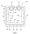
FIG. 7 is a view of a partial housing assembly according to one embodiment of the invention;
FIG. 8 is an internal view of a Liquid Crystal Display (LCD) display housing for a computer;
FIG. 9 is a diagram of an antenna according to one embodiment of the invention;
FIGS. 10A and 10B are cross-sectional drawings of a antenna pole according to one suitable embodiment;
FIG. 11A is a cross-sectional diagram of a conventional computer housing exhibiting excessive amounts of flexibility;
FIG. 11B is a cross-sectional diagram of the computer housing that includes a series of ridges (or inserts);
FIG. 12 is a diagram of a computer housing according to one embodiment of the invention;
FIG. 13 is a broken perspective view of a LCD display screen housing according to one embodiment of the invention;
FIG. 14A is a cross-sectional diagram of a display apparatus according to one embodiment of the invention;
FIG. 14B is a cross-sectional diagram of a display apparatus according to one embodiment of the invention;
FIG. 14C is a cross-sectional diagram of a display apparatus according to one embodiment of the invention; and
FIG. 14D is a cross-sectional diagram of a display apparatus according to one embodiment of the invention.
DETAILED DESCRIPTION OF THE INVENTION
The invention pertains to an improved housing for a computing device. More particularly, a first aspect of the invention pertains to a computer housing having a logo or other symbol that can be illuminated using light from the backside of a display panel. A second aspect of the invention pertains to a suspended frame is able to support a display panel within a display housing. A third aspect of the invention pertains to a computing device provided with an internal antenna. A fourth aspect of the invention pertains to a stiffener for a computer housing so as to increase the rigidity and strength of the computer housing. A fifth aspect of the invention pertains to illumination of design elements or features using light from the backside of a display panel. A sixth aspect of the invention pertains to a lid for a computing device, such as a portable computer, that is provided with a translucent housing.
Embodiments of the invention are discussed below with reference to FIGS. 1-14D. However, those skilled in the art will readily appreciate that the detailed description given herein with respect to these figures is for explanatory purposes as the invention extends beyond these limited embodiments.
FIG. 1 is a perspective diagram of a portable computer 100. The portable computer 100 includes a base 102 and a lid 104. The base 102 houses internally various integrated circuit chips and other circuitry to provide computing operations for the portable computer 100. The integrated circuit chips and other circuitry include a microprocessor, Read-Only Memory (ROM), Random-Access Memory (RAM), a disk drive, a battery, and various input/output (I/O) support circuitry. The base 102 also includes a keyboard 106 that allows a user of the portable computer 100 to enter alphanumeric data. The base 102 also includes a track pad 108 and associated buttons 110 and 112. The track pad 108 is an input device for the portable computer 100 and generally represents an input pointer device. The associated buttons 110 and 112 allow a user to make a selection with respect to a graphical user interface. Additionally, the base 102 includes a power switch 114 and miscellaneous switches 116.
The lid 104 is coupled to the base 102 by way of a hinge mechanism (not shown). As such, the lid 104 can rotate into an open position or a closed position with respect to the base 102. As illustrated in FIG. 1, the lid 104 is in the open position. The lid 104 contains a light emitting diode (LCD) display 118. The LCD display 118 is visible to a user of the portable computer 100 when the lid 104 is in the open position, such as illustrated in FIG. 1. The LCD display 118 is surrounded at a peripheral region by a bezel 120 that serves to support the LCD display 118 in its assembled position within the lid 104. When the lid 104 is in a closed position, an outer surface 122 of the lid 104 is visible but the LCD display 118 and the bezel 120 are no longer visible to the user.
According to a first aspect of the invention, a logo or other symbol provided on a housing can be illuminated using light from the backside of a LCD panel. The light can be direct, reflected, or both. The illumination is provided by use of otherwise wasted light.
FIG. 2 illustrates a display apparatus 200 according to one embodiment of the invention. The display apparatus 200 illustrated in FIG. 2 represents an assembly diagram for the display apparatus 200.
The display apparatus 200 includes a translucent housing 202. The translucent housing 202 has an outer surface 204 and an inner surface 206. In one implementation, the translucent housing 202 is a lid of a portable computer, such as the lid 104 illustrated in FIG. 1. A cosmetic shield 208 is placed against the inner surface 206 of the translucent housing 202. The cosmetic shield 208 provides a uniform, clean look for the translucent housing 202 when viewed from the outer surface 204. In other words, the cosmetic shield 208 provides the uniform, clean look and masks out the undesirable appearance of other internal components to the display apparatus 200. A suspended frame 210 is connected to the translucent housing 202 at the inner surface 206. The suspended frame 210 typically affixes itself with respect to the translucent housing 202 at the periphery of the translucent housing 202. An EMI shield 212 can be placed within the suspended frame 210 or between the suspended frame 210 and the cosmetic shield 208. The EMI shield 212 is a metal sheet have a plurality of holes. A LCD panel 214 is affixed to the suspended frame 210. Hence, the suspended frame 210 operates to secure the position of the LCD panel 214 with respect to the translucent housing 202. The EMI shield 212 serves to block emissions from at least the back-side of the LCD panel 214. A bezel 216 provides a border around the edge of the front-side of the LCD panel 214 and typically attaches to a peripheral region of the translucent housing 202.
FIG. 3A is a diagram of an EMI shield 300 according to one embodiment of the invention. The EMI shield 300 represents an embodiment of the EMI shield 212 illustrated in FIG. 2. The EMI shield 300 includes a plurality of holes 302 which are typically provided in a predetermined pattern (e.g., grid pattern). Even though the EMI shield 300 includes a plurality of holes 302, when placed adjacent to one side of a LCD panel, the EMI shield is able to limit electromagnetic emissions from the display apparatus due to the back-side of the LCD panel. The EMI shield 300 also includes a solid region 304 through which there are no holes. In FIG. 3A, the solid region 304 is in the form of a symbol or a company logo, such as an apple which is the company logo of Apple Computer, Inc. In general, the solid region 304 provides a reflection area that is utilized to provide symbol illumination as discussed in detail below. However, it should be noted that the solid region 304 need not have the same shape or configuration as the symbol to be illuminated. For example, the solid region 304 illustrated in FIG. 3A could be a square region that is at least as large as the symbol to be illuminated.
FIG. 3B is a diagram of a cosmetic shield 306 according to one embodiment of the invention. The cosmetic shield 306 can be formed from a variety of materials. For example, in one implementation, cosmetic shield 306 is a thin sheet of aluminum. Other suitable materials for the cosmetic shield 306 include, for example, paper or plastic. The cosmetic shield 306 can be any of a variety of different colors or multiple colors. Although the cosmetic shield 306 generally reflects light incident from the LCD panel, the cosmetic shield 306 also include an opening 308. The opening 308 corresponds to the symbol to be illuminated. The opening 308 provides an outlet for some of the light being reflected from the solid region 304 of the EMI shield 300 towards the cosmetic shield 306. Accordingly, the light passing through the opening 308 illuminates the logo or other symbol.
FIG. 4 is a diagram of a symbol illumination system 400 according to one embodiment of the invention. The symbol illumination system 400 operates to illuminate a symbol at a translucent portion of a housing using light provided by a display panel. The symbol illumination system 400 explains how a symbol is illuminated by a display apparatus, such as the display apparatus 200 illustrated in FIG. 2, according to one embodiment of the invention.
The symbol illumination system 400 includes a LCD panel 402. The LCD panel 402 emits light in a primary direction 404 as well as in a secondary direction 406. The primary direction 404 is associated with the direction towards a viewing side of the LCD panel 402. A user of the LCD panel 402 (or the computer to which the LCD panel 402 is associated) typically views a display screen from the viewing side of the LCD panel 402. The secondary direction 406 represents light being emitted from the back-side of the LCD panel 402 towards the housing which supports the LCD panel 402. Generally, the second direction 406 is opposite the primary direction. The light being emitted in the secondary direction 406 then interacts with an EMI shield 408. The EMI shield 408 includes a plurality of holes through which light may pass. As an example, the EMI shield 408 can be constructed such as the EMI shield 300 illustrated in FIG. 3A. In any case, when the light emitted in the secondary direction 406 strikes the EMI shield 408 at one of the respective holes within the EMI shield 408, then such light 412 can pass through the EMI shield 408. On the other hand, the light emitted in the secondary direction that does not strike the EMI shield 408 at a hole (but instead a solid region), such light 410 is reflected back toward the LCD panel 402.
The light 412 that does pass through the EMI shield 408 next impinges upon a cosmetic shield 414. The light 412 striking the cosmetic shield 414 is reflected from the cosmetic shield 414 back towards the EMI shield 408 as reflected light 416. Thereafter, a portion of the reflected light 416 that reflects back to a solid region 417 (e.g., solid region 304) of the EMI shield 408 is then again reflected back from the solid region 417 of the EMI shield 408 towards the cosmetic shield 414 as twice reflected light 418. At least a portion of the twice reflected light 418 is directed to an opening 420 in the cosmetic shield 414. The portion of the twice reflected light passing through the opening 420 then passes through a translucent housing 422 to produce an illuminated image 424 at an outer surface of the translucent housing 422. More particularly, the opening 420 within the cosmetic shield 414 is configured in accordance with an image of the symbol to be illuminated. For example, when the opening 420 is formed such as the opening 308 in the cosmetic shield 306 illustrated in FIG. 3B, the illuminated image 424 at the outer surface of the translucent housing 422 would correspond to an illuminated apple symbol. However, as noted above, any graphic or symbol can be illuminated in this manner.
FIG. 5 is a flow diagram of design illumination processing 500 according to one embodiment of the invention. The design illumination processing 500 is, for example, performed by a symbol illumination system, such as the symbol illumination system 400 illustrated in FIG. 4. Typically, the symbol illumination system would be provided on an electronic device having a display panel for displaying information to a user. The design illumination processing 500 enables a design (e.g., symbol, logo or other graphic) on a back surface of a housing for the display panel of the electronic device to be illuminated using reflected light from the light panel.
The design illumination processing 500 begins by emitting 502 light from a light panel in first and second directions. Typically, the first direction is a primary direction in which light is emitted from the light panel, and the second direction is a secondary in which light is also emitted. Typically, the amount of light emitted in the second direction is substantially less than the amount of light emitted in the first direction. Often, the light emitted in the second direction is a side-effect not normally desired (i.e., a side-effect) but such light is utilized by the invention.
Next, a portion of the light emitted in the second direction from the light panel is reflected 504 from a cosmetic shield. In other words, the light emitted in the second direction is reflected back in substantially the first direction by the cosmetic shield. Typically, the cosmetic shield reflects most of the light striking its surface, but some of the light can also be absorbed.
Then, a portion of the light reflected from the cosmetic shield is reflected 506 back towards the cosmetic shield using a reflecting surface. The reflecting surface can be provided in a number of ways, including as a reflecting material provided on a portion of a back surface of the light panel or an intermediate reflecting region provided between the cosmetic shield and the back surface of light panel. Examples of an intermediate reflecting region are the solid region 304 of the EMI shield 300 in FIG. 3A or the solid region 417 of the EMI shield 408 illustrated in FIG. 4.
Thereafter, a portion of the reflected light from the reflecting surface is passed 508 through an opening in the cosmetic shield having a predetermined design and then through a corresponding portion of an adjacent housing. In other words, light reflected from the cosmetic shield back to the reflecting surface then back again towards the cosmetic shield will eventually have a portion thereof pass through the opening in the cosmetic shield. The opening in the cosmetic shield leads to a housing that is adjacent to the cosmetic shield. Also, at least a portion of the housing adjacent the cosmetic shield is translucent. Consequently, the light passing through the opening in the cosmetic shield also then passes through a corresponding portion of the (translucent) housing that is adjacent to the opening in the cosmetic shield, thereby illuminating the predetermined design in the housing. Once the design is illuminated, the design illumination processing 500 is then complete and ends.
The design being illuminated is located adjacent the opening in the cosmetic shield. As noted above, the design can be provided in the translucent portion of the housing adjacent the opening in the cosmetic shield. The design could also be provided by a separate design piece of translucent material that is inserted and affixed within an opening in the (translucent or non-translucent) housing. In such case, the opening in the housing would be adjacent the opening in the cosmetic shield. Still further, a light pipe or light guide could direct the light to the design and thus not be adjacent the opening in the cosmetic shield.
According to a second aspect of the invention, a suspended frame is able to support a LCD panel within a display housing with attachments being made at upper and lower peripheral surfaces. The suspended frame is particularly well suited for use with a translucent display housing.
FIG. 6A is a top view of a suspended frame 600 according to one embodiment of the invention. FIG. 6B is a right side view of the suspended frame 600. The suspended frame 600 illustrated in FIG. 6A and FIG. 6B represents one embodiment for the suspended frame 210 illustrated in FIG. 2.
The suspended frame 600 includes an outer periphery 602 and an inner periphery 604 that form the frame. However, the suspended frame 600 could alternatively be a sheet which would provider greater support at the additional manufacturing cost and additional weight. Typically, the suspended frame 600 is a metal structure, such as sheet metal. The suspended frame 600 is used to support a LCD panel, such as the LCD panel 214 illustrated in FIG. 2. The suspended frame 600 includes a left side 606, a right side 608, a top side 610, and a bottom side 612. The left side 606 and the right side 608 have side edges 614 that extend outward at the outer periphery 602 of the left side 606 and the right side 608. Additionally, the bottom side 612 includes a bottom edge 616 that extends outward at the outer periphery 602 of the bottom side 612. In order to affix the LCD panel to the suspended frame 600, the suspended frame 600 includes holes 618 at the left side 606 and the right side 608. The top side 610 includes holes 620 and the bottom edge 616 includes holes 622. The holes 620 and 622 are used to affix or mount with respect to the suspended frame 600 as discussed below.
The suspended frame 600 then in turn mounts to a housing. For example, the housing can be the translucent housing (lid) 202 illustrated in FIG. 2. FIG. 7 is a view of a partial housing assembly 700 according to one embodiment of the invention. The partial housing assembly 700 illustrates the suspended frame 600 being affixed or attached to a housing 702. The housing 702 includes an inner surface 704 and an outer surface 705. At the periphery of the inner surface 704, an outer lip 706 is formed. The outer lip 706 typically extends around the periphery of the translucent housing 702. At a bottom side of the outer lip 706 a plurality of holes 708 are provided through the outer lip 706. The holes 708 through the bottom side of the outer lip 706 align with the holes 622 in the bottom edge 616 of the bottom side 612 of the suspended frame 600. By threading screws through the holes 708 and into the corresponding holes 622, the bottom side of the suspended frame 600 is affixed to the bottom side of the housing 702. The housing 702 also includes the plurality of tabs 710 at a top side of the housing 702. In one embodiment, the tabs 710 are constructed as part of the housing 702 and extend downward from the top side over the top side 610 of the suspended frame 600. The tabs 710 are used to affix or mount the top side 610 of the suspended frame 600 to the top side of the housing 702. Typically, screws would be threaded through openings 712 in the tabs 710 and through the corresponding holes 620 in the top side 610 of the suspended frame 600. It should be noted that in this embodiment, the suspended frame 600 is coupled to the housing 702 only at the top side and at the bottom side near the periphery. As such, when the housing 702 is translucent, the outer surface 705 of the translucent housing provides a smooth, uniform appearance (without having visual detractions due to large numbers of screws, etc.) even though the suspended frame 600, as well as the LCD panel coupled thereto, are securely fastened to the translucent housing.
Still further, the suspended frame 600 is connected to a base housing (e.g., base 102 of FIG. 1) through a hinge mechanism (not shown). The housing 702 then, as noted above, attaches to the suspended frame 600. The LCD display (e.g., 214) attaches to the suspended frame 600. A bezel (e.g., bezel 120) couples to the housing 702 or the suspended frame 600. Hence, when the lid (e.g., lid 104) is assembled, the bezel and the housing sandwiches the suspended frame 600 and the LCD display. Another advantage of the suspended frame 600 is then that the functional components within the lid are able to be easily serviced, tested or assembled because the bezel and housing can be removed while leaving the LCD display operable and attached to the suspended frame 600 (as well as the hinge mechanism).
According to a third aspect of the invention, a portable computing device is provided with an internal antenna. In one embodiment, the antenna is internal to a computer housing (e.g., LCD display housing).
FIG. 8 is an internal view of a LCD display housing 800 for a computer. The LCD display housing 800 has a housing 802. The housing 802 has an outer surface 804 and an inner surface 806. Affixed to the inner surface of the housing 802 is a LCD display 808. The peripheral portion of the LCD display 808 and brackets used to affix the LCD display 808 to the inner surface 806 of the housing 802 can be cosmetically masked with a cosmetic frame 810. In one implementation, the cosmetic frame 810 is a thin sheet of aluminum. The cosmetic frame 810 is useful when the housing has translucent portions.
The housing 802 is also configured to enclose an antenna. The inner surface 806 of the housing 802 is also provided with recesses 812 and 813 for receiving the antenna. In one implementation, the recesses 812 and 813 are configured to coincide with the shape of the antenna device so that the assembly of the antenna device to the inner surface 806 of the housing 802 is performed with ease (and likely without any need to otherwise adhere or fasten). In most instances, the antenna device is disposed at the outer perimeter of the inner surface 806 of the housing 802. For RF interference reasons, it is desirable to place the antenna as far away from metal surfaces within the housing 802, namely, the LCD display 808 and the brackets used to affix the LCD display 808 to the inner surface of the housing 802. Also, when the cosmetic shield 810 is provided and made of metal, it is also desirable to place the antenna as far from the cosmetic shield as practicable. Given the space constraints of the LCD display housing 800, the housing 802 generally conforms to the shape and size of the LCD display 808. However, to provide a separation gap 814, the housing 802 is provided with sufficient area on sides 816 and 818. The recesses 810 are thus provided on the sides 816 and 818 spaced the separation gap 814 from the nearest interfering metal surfaces. In one implementation, the separation gap 814 is 12 mm, but such separation is dependent on the mass of metal in the LED display housing.
FIG. 9 is a diagram of an antenna 900 according to one embodiment of the invention. The antenna 900 has a first antenna pole 902 and a second antenna pole 904. Both the first antenna pole 902 and the second antenna pole 904 are connected to antenna cables 906 and 908. When the antenna 900 is attached to the housing 802, the first antenna pole 902 fits into the recess 812 and the second antenna pole 904 fits into the recess 813. The antenna cable 908 couples the first and second antenna poles 902 and 904 together. When the antenna 900 is attached to the housing 802, the antenna cable 908 fits into a groove 820 in an upper peripheral portion of the inner surface 806 of the housing 802 (see FIG. 8). The antenna cable 906 is provided between the LCD display 808 and the inner surface 806 of the housing 802 and serves to electrically couple the antenna 900 to the computing device.
Although not shown in FIGS. 8 and 9, after the antenna 900 is attached to the housing 802, a bezel (not shown) is then attached to the housing 802 to provide a front surface to the housing 802. The attachment of the bezel serves to complete the assembly of the housing 802. The attachment of the bezel can be facilitated by snaps 822 and 824 provided on the sides 816 and 818 respectively. In one implementation, the bezel is translucent and covers the cosmetic shield 810 as well as the more peripheral portions of the housing 802. In such an implementation, the antenna 900 together with the recesses 812 and 813, the groove 820 and the snaps 824 all provide a generally uniform design line within the housing. As such, even when the housing (at least the peripheral portion) is translucent, the antenna is largely unnoticeable to the untrained observer from the exterior of the housing.
While the above embodiments refer to the use of a dipole antenna, a monopole antenna or other antenna designs could also be used. While the recesses and grooves in the inner surface of the housing serves to provide uniform design features in a translucent housing, if a non-translucent housing were used, such recesses and grooves would not be as important. It should also be noted that to provide a sufficient separation gap 814, the sides 816 and 818 could be extended outward primarily only in the vicinity of the recesses 812 and 813 as opposed to the entire length of the sides 816 and 818.
The one or more antenna poles provided with the antenna can be formed in a variety of ways. FIGS. 10A and 10B are cross-sectional drawings of a antenna pole 1010 according to one suitable embodiment. The antenna pole 1010 couples to a cable 1012 (e.g., coaxial cable) that has an inner conductor and an outer conductor (not shown). A dielectric material (not shown) is disposed between the inner conductor and the outer conductor. The antenna pole 1010 is used to transmit and receive information with respect to a computing device associated with the antenna pole 1010. Typically, the cable has a distal end coupled to a portion of the antenna pole 1010 and a proximal end coupled to a circuit board or related device (e.g., transceiver) of the computing device. In one implementation, the cable 1012 is a coaxial cable. However, in general, the cable 1012 can be any suitable wiring having two conductors.
In the embodiment shown in FIGS. 10A and 10B, the antenna pole 1010 includes a first conductor 1014 that is operatively coupled to the outer conductor at the distal end of cable 1012. The first conductor 1014 flares back around the outer peripheral surface of the cable 1012. In this manner, a substantial portion of first conductor 1014 is disposed around the outer periphery of the cable 1012. In some situations, a gap 1016 is formed between the inner peripheral surface of the first conductor 1014 and the outer peripheral surface of the cable 1012 (as shown in the cross section C-C of FIG. 10B). In one implementation, the first conductor 1014 flares back about 23 mm in length, and the gap 1016 is 0.3 to 0.4 mm. Typically, the first conductor 1014 is formed from a conductive metal (e.g., copper). Also, as shown in FIGS. 10A and 10B, the first conductor 1014 may be configured in two separate sections that are both flared back on opposite sides of the outer periphery of the cable 1012.
The antenna pole 1010 also includes a second conductor 1018 that is operatively coupled to the inner conductor at the distal end of the cable 1012. The second conductor 1018 extends outward away from the distal end of the inner conductor of the cable 1012. In one implementation, the second conductor 1018 is preferably about 23 mm from the distal end of the inner conductor 1018. Typically, the second conductor 1018 is formed from a conductive metal (e.g., copper). It should be noted that the first conductor 1014 and the second conductor 1018 may be integrally formed with the respective conductors of the cable 1010. In other words, the first conductor 1014 could be a portion of the outer conductor of the cable 1012, and the second conductor 1018 could be a portion of the inner conductor of the cable 1012.
The antenna pole 1010 has an antenna housing 1020 that is disposed around the first conductor 1014, the second conductor 1018, and a portion of the cable 1012. The antenna housing 1020 can be formed from a wide range of materials. By way of example, the antenna housing 1020 can be made of polycarbonate. In one implementation, the outer peripheral surface of first conductor 1014 is adjacent to the inner peripheral surface of the antenna housing 1020. Additionally, in one embodiment, there can be a space 1022 between the inner peripheral surface of the antenna housing 1020 and the outer peripheral surface of second conductor 1018. In such an embodiment having the space 1022, the antenna housing 1020 can also include a second conductor support member 1024 to support the second conductor (as shown in cross section D-D of FIG. 10B).
The antenna housing 1020 further includes a plurality of support members 1026 for supporting the cable 1012 line inside the antenna housing (as shown in cross section B-B of FIG. 10B). The supporting members 1026 can be separate pieces or integrally formed with the antenna housing 1020.
The antenna housing 1020 can be formed as a two-piece construction, including a first housing member 1028 and a second housing member 1030. In this case, the supporting members 1026 can be integrally formed with the first and second housing members 1028 and 1030. As shown, at the cross section B-B of FIG. 10B, the supporting members 1026 not only support the cable 1012 inside the antenna housing 1020 but also properly space the conductors 1014 apart from the cable 1020. With the two-piece construction, a first mating portion 1032 of the first housing member 1028 and a second mating portion 1034 of the second housing member 1030 are structurally coupled and held together with shrink tubing 1036 that surrounds a portion of the outer peripheral surface of the antenna housing 1020 (see cross section A-A of FIG. 10B).
There is an increasing trend in the computer industry, particular with respect to portable computers, to reduce size, weight and thickness. For the most part, any computer part that can be made smaller generally is made smaller to accommodate this need. By way of example, the wall thickness of the computer housing has been made thinner over the years. In most instances, decreased wall thickness reduces the overall thickness and weight of the computer, both of which are desired to make a portable computer more portable.
However, making the outer structure thinner to reduce computer weight and thickness has its drawbacks, typically the enclosure becomes more flexible. As a general rule, thicker walls mean stronger walls. Consequently, the thinner outer structure may not offer enough support to protect the internal components of the computer. Even when the thinner outer structure is strong enough to protect the internal components, users who expect rigid structures are unsatisfied.
Furthermore, recently, computer housing designs have become more decorative, thereby creating more complex shapes. These complex designs create structural problems that often result in even more flexible outer shells. Typically the complex shapes are contoured or curvilinear, which generally reduces the overall strength of the computer housing. The complex shapes also make it increasingly difficult to provide any internal support to offset these problems. For the most part, rectilinear designs, which include most of the computer housings on the market today, are stronger. The rectilinear design provides rigid support and is fairly easy to support with internal support members.
FIG. 11A is a cross-sectional diagram of a conventional computer housing 1110 exhibiting excessive amounts of flexibility. The computer housing 1110 includes a top member 1112 and a bottom member 1114. Typically, the top member 1112 is structurally coupled to bottom member 1114 wherein an open space or volume 1116 is created therebetween. For the most part, this volume contains the different parts or components of a computer or display (e.g., circuit boards, key boards, display screen, etc.). Although, there are things contained in the volume, a significant portion of the volume is left unused. If a flexible (non-rigid) material is used to form the top member or bottom member, then the volume will be left structurally unsupported. By way of example, when a force 1118 is supplied to the computer housing 1110 (i.e., outer shell) at a position away from its members sides, the computer housing 1110 will deform under the force 1118, creating a “feel” (“squishy feel”) which is considered by users indicative of low quality. As a result of the deforming, the force 1118 can also damage the internal parts or components of the computer or display (e.g., display screen).
In general, there are two ways to design a housing structure, one is to have a strong outer shell, the other is to have an internal skeleton structure. As a general rule, when the outer shell becomes increasingly thin (i.e., flexible) it is difficult to have a strong outer shell and therefore an internal support skeleton is usually provided to strengthen the thin outer shell. By way of example, ribs or inserts are typically used to increase the strength and rigidity of the outer shell.
FIG. 11B is a cross-sectional diagram of the computer housing 1110 that includes a series of ridges 20 (or inserts). Typically, the ridges 20 provides support to both the bottom member 1114 and the top member 1112 of the computer housing 1110. The ridges may be configured as part of one of the members 1112, 1114 or may act as a separate piece. Although, the computer housing 1110 (outer shell) is better supported and has more rigidity, the volume 1116 created by the top member 1112 and the bottom member 1114 still includes unused space. Hence, if force 1122 is applied to the surface of the top member 1112, then the unsupported space will deform (i.e., flexible), albeit less than without the ribs 1120. If force 1124 is applied to the surface of the top member 1112 at the rib 1120, then the surface on the opposing side of the rib 1120 receives a large portion of the force 1124 which may damage sensitive parts. For example, if the bottom member 1114 were a LCD display screen, then the rib 1120 may transfer the full force of the force 1124 to the LCD display screen, which may damage the LCD display screen.
According to a fourth aspect of the invention, a computer housing with a stiffener is provided. The stiffener is configured to increase the rigidity and strength of the computer housing, which advantageously allows the thickness of the computer housing walls to be decreased. Thus, the use of the stiffener not only protects internal components but also provides a firmer feel to the housing. The stiffener can have a large surface area and be positioned between the top member and the bottom member of a housing to distribute external loads (e.g., pressures, forces) more evenly across the entire housing. More specifically, the stiffener can be configured to conform to the internal features of the housing that oppose (or are adjacent to) the stiffener, thereby maximizing the load distribution. That is, the stiffener advantageously fills the unused volume of the housing. Furthermore, the stiffener is configured to work in housings that have complex shapes (e.g., curvilinear) thereby allowing more decorative housings.
Accordingly, the stiffener provides a non-traditional solution to a load distribution problem. Typically, the computer industry has always used ribs, inserts, a thick outer shell and/or rectilinear shapes to support the computer housing. For the most part, the computer industry has not filled unused volumes within the computer housing because of the additional weight.
FIG. 12 is a diagram of a computer housing 1210 according to one embodiment of the invention. The computer housing 1210 represents a housing used with a computing device such as a computer housing or cabinet or a display housing. The computer housing 1210 includes a first member 1212 and a second member 1214. Typically, the walls of each member 1212 and 1214 are thin and flexible. As mentioned above, the thin members 1212 and 1214 reduce the overall thickness and weight of the housing. The computer housing walls are typically formed from a plastic material such as polycarbonate (ABS). Normally, the first member 1212 is structurally coupled to the second member 1214 to form the outer shell of the housing 1210 and form a volume therein. Although the computer housing has been described as having a first and second members it should be noted that the computer housing may be integrally formed (e.g., one piece) or formed from a plurality of members (i.e., third member, fourth member, etc.).
Conventionally, the internal components or parts of the computer (e.g., printed circuit boards, LCD displays) are housed within the volume created within the housing 1210. However, in most situations, there remains a portion of the volume that is left unused (e.g., a void or open space). A stiffener 1226 is disposed within the housing 1210 to substantially fill any unused volume between the first and second members. Basically, the stiffener 1226 is configured to fill the unused volume (see FIG. 12). Moreover, the outer peripheral surface of the stiffener 1226 conforms to the shape of the adjacent components or inner peripheral surfaces of the first member and second member. The stiffener 1226 can be configured to provide clearance (or slots) for features such as connectors and wires. The stiffener 1226 can also include holes or openings (cavities) for internal components or parts. Additionally, the stiffener 1226 may include protrusions and depressions that coincide with the shape (geometry) of the components, parts or housing within the volume.
Because the stiffener 1226 fills the unused volume of the housing, forces that exerted on the outer peripheral surface of the housing are distributed over a larger surface area. Basically, if force 1228 is applied to the external surface of first member 1212, the single point of contact will be distributed throughout the stiffener 1226. In essence, the combination of the first member 1212, second member 1214, internal components and stiffener 1226 form a laminate structure that provides resistance to point pressure loading.
Furthermore, the stiffener 1226 may be fastened to at least one of the members or be tightly disposed between the members and components. In one implementation, the stiffener 1226 is fastened to the first member 1212 using a stiffener lip (not shown). Basically, the lip can be an extension of the first member and is configured to hold the stiffener 1226 in place. The lip may also be used as a locating ridge for determining the correct placement of the stiffener 1226 with respect to the first member. In another implementation, the stiffener 1226 may be structurally coupled to the first member or the second member using an adhesive. It still other implementations, other techniques can be used to hold the stiffener 1226 in place (e.g., screws, rivets, etc.).
Generally, the stiffener 1226 does not completely or overly fill the unused volume. Instead, a gap is provided so that the stiffener will not exert unwanted pressure on the surface of one of the components or the members while in a static condition. By way of example, if the first member is an LCD display screen, the static pressure exerted on the back side of the LCD display screen may damage the LCD display screen.
In one embodiment, the stiffener 1226 should be formed from a material that can substantially be implemented in a portable computer environment (low flammability, low static charge, low weight, and low compressibility). In a preferred embodiment of this invention, the stiffener is formed from foam. Advantageously, many foam materials fall within the above criteria, especially the weight. The foam may be machined, molded, or die cut to the desired shape. Preferably, packaging foam is used. As examples, the stiffener can be formed from polyurethane, expanded polystyrene, expanded polypropylene or expanded polyethylene. All of these examples are light weight, have compressible strength (substantially rigid) and are easily formed to different shapes. In any case, it should also be noted that the above description is not limiting and any material that is substantially rigid and lightweight (e.g., rubber, plastic, silicon) may be used.
In another embodiment of the invention, lightweight stiffening is provided for a portable computer housing. In this particular embodiment, the computer housing is a LCD display screen housing. FIG. 13 is a broken perspective view of a LCD display screen housing 1310 according to one embodiment of the invention. The LCD display screen housing 1310 includes a bezel (frame) 1312 and an LCD display screen 1314 that form a front portion of the LCD display housing 1310. The LCD display screen housing 1310 further includes a back portion 1316 of the LCD display screen housing 1310. The back portion 1316 provides an impact resistant shell for protecting the backside of the LCD display screen 1314. As shown, both the bezel 1312 and the LCD display screen housing 1310 have complex shapes (internal and external) as well as portions that are curvilinear (e.g., decorative design).
A foam stiffener 18 is disposed between the front portion and the back portion 1316 of the LCD display screen housing 1316. Additionally, the outer peripheral surfaces of the foam stiffener 1318 are configured to conform the inner peripheral surfaces of the front portion (e.g., the LCD display screen 1314 and perhaps the bezel 1312) and the back portion 1316 of the LCD display screen housing 1316. Furthermore, the foam stiffener 1318 can also include a depression 1320 for disposing a connector and a protrusion 1322 that fits into the backside of LCD display screen 1314, and an opening 1324 for lighting a portion of the LCD display screen housing 1316. As shown, the foam stiffener 1318 is advantageously configured to fill the complex shapes associated with the bezel 1312, the LCD display screen 1314, the LCD display screen housing 1316 and connectors. It should be noted that the foam stiffener 1318 is not limited by any one of the above arrangements (e.g., depressions, protrusions, openings) and any combination thereof may be used. Moreover, all three structures (e.g., the front portion, the foam stiffener 1318 and the back portion 1316) form a laminate structure (when coupled together) for the LCD display screen housing 1310 that provides a rigid structure with a firm feel (not malleable or squishy) that is substantially resistant to point pressures.
In an alternate embodiment, the foam stiffener can be used as the entire computer housing and fabricated to fit all the parts and the components of the computer. To protect the outer peripheral surface of the foam, a coating can be applied over the outer surfaces to form a shell.
Although the foam stiffener 1318 has a one-piece construction, the foam stiffener 1318 can utilize multiple pieces. In another alternate embodiment, the foam may be injected into the housing to fill the unused volume between the front portion and the back portion.
In other embodiments, the foam stiffener can incorporate an antenna or an EMI shield. That is, an antenna or an EMI shield could be patterned onto or internal to the foam stiffener. In one implementation, the foam stiffener is primarily a foam as noted above but also could include copper and nickel to provide the antenna or the EMI shield.
Also, the foam stiffener is generally very light weight. Nevertheless to further reduce weight, the foam stiffener can include weight reducing apertures. These apertures (cavities or holes) are selected so as to reduce weight while maintaining rigidity. Such apertures may be patterned or randomly placed.
Furthermore, the foam stiffener provides for a firm feel to the computer housing assembly, which is particularly useful given the flexible nature of the increasingly thin-walled plastic products and the constraints of typical stiffening methods such as ribs or inserts. Increasingly thinner products means there is little room for ribs, while weight reduction efforts mean that traditional stiffening materials such as aluminum or mica are too heavy. The foam stiffener is very lightweight and can also be used to replace other functional and structural parts (sheet metal, plastics, etc.) and thus reduce cost, weight and parts count. The relatively soft nature of the foam stiffener acts as a load spreader which not only reduces likelihood of damaging parts or components internal to the housing, but also increases the units ability to survive point source pressures on the housing. In fact, in a ball pressure test for a portable computer, the display screen apparatus 1310 according to the invention passed the test, while a display screen apparatus without the benefits of the invention failed the test.
According to a fifth aspect of the invention, a logo, symbol or other device provided on a housing can be illuminated using light from the backside of a LCD panel. The light can be direct, reflected, or both. The illumination is provided by use of otherwise wasted light. The fourth aspect is similar to the first aspect but relies less on reflected light and is perhaps better suited for a non-translucent housing.
FIG. 14A is a cross-sectional diagram of a display apparatus 1400 according to one embodiment of the invention. The display apparatus 1400 includes a display housing 1400 that contains a LCD display 1404. The LCD display 1404 has a front surface 1406 and a back surface 1408. When the LCD display 1404 is power-on, the LCD display 1404 emits light primarily from the front surface 1406 but also emits some light from the back surface 1408. The fifth aspect of the invention serves to make use of the light emitted from the back surface 1408 that would otherwise go unused and thus wasted. The display apparatus 1400 also includes a bezel 1410 and 1412 to frame out the front surface 1406 of the LCD display 1404 and provide a smooth, uniform front surface for the display housing 1402.
The display housing 1402 also includes a translucent portion 1414 through which the light from the back surface 1408 of the LCD display 1406 can pass so as illuminate the translucent portion. In one embodiment, the display housing 1402 is generally opaque but includes the translucent portion 1414 where the light is desired. For example, a symbol, logo or other device can be provided at the translucent portion 1414 to be illuminated when the LCD display 1406 is powered-on. The translucent portion 1414 can be formed into the display housing 1402. Alternatively, an opening or hole can be provided in the display housing 1402 and a translucent plug or insert can be provided in the opening or hole.
Thus, the fifth aspect of the invention allow for the illumination of design elements or features. The fifth aspect of the invention also serves to provide a visual indication of whether the LCD panel is on. When a computer system utilizing the display apparatus 1400 enters a sleep mode, the LCD panel is typically power-off so that light is not emitted from the LCD display 1406 and thus the illumination of the design element or feature stops. A user is thereby informed that the computer system is in the sleep mode when there is no illumination of the design element or feature. Another advantage of the fifth aspect is that it requires very little space between the back surface 1408 and the inside surface of the display housing 1402. Still another advantage of the invention is that the illumination is provided without requiring any additional power because the light used is otherwise wasted.
The display housing 1400 shown in FIG. 14A has a curved cross-section for industrial design considerations, namely for better user appeal. However, the display housing 1400 can take a variety of different forms.
FIG. 14B is a cross-sectional diagram of a display apparatus 1420 according to one embodiment of the invention. Although the display apparatus 1420 is similar to the display apparatus 1400 of FIG. 14A, the display apparatus 1420 includes a light diffuser 1422. As shown in FIG. 14B, the light diffuser 1422 is provided on an inner surface of the display housing 1402 at the translucent portion 1414. More generally, the light diffuser 1422 can be provided any where between the back side 1408 of the LCD display 1404 and the outer surface of the housing display 1402 at the translucent portion 1414.
The light diffuser 1422 operates to enable control of intensity and color of the illumination at the translucent portion 1414. In one embodiment, the light diffuser 1422 is a label. The light diffuser 1422 can have a graphic printed thereon, can have multiple colors, and can use varying thickness all to assist with the control over the intensity and color of the illumination provided. For example, the material for the light diffuser 1422 can be general label stock, Mylar, Lexan (from General Electric) or any other material that is thin and translucent. Particular graphics or color shades can be printed on the light diffuser 1422 if desired.
The ability to control the light intensity of the illumination is useful to normalize the illumination yielded by difference vendors of the LCD displays. For example, in a LCD display from a first vendor emits light at a first intensity from its back surface and a LCD display from a second vendor emits light at a second intensity (which is greater than the first intensity) from its back side, then the illuminated logo, symbol or device would appear brighter in the display housing using the LCD display from the second vendor. Hence, the light diffuser 1422 can be used to normalize the intensity of the illumination provided. For example, the thickness of the light diffuser 1422 (label) used with the display housing using the LCD display from the second vendor can be increased (as compared to the thickness used with the display housing using the LCD display from the first vendor) to thus reduce its translucency.
FIG. 14C is a cross-sectional diagram of a display apparatus 1440 according to one embodiment of the invention. Although the display apparatus 1440 is similar to the display apparatus 1420 of FIG. 14B, the display apparatus 1440 further includes an illuminated area 1442 in the bezel 1412 and a light guide 1444. As shown in FIG. 14B, the light guide 1444 has a first end 1446 that receives a portion of the light emitted from the back surface 1048 of the LCD display 1404. The light received by the first end 1446 is then directed through the light guide 1444 and output at a second end 1448. The second ends 1448 is coupled to the illuminated area 1442 so that the light directed through the light guide 1444 is coupled to the illuminated area 1442, thereby illuminating the illuminated area 1442.
FIG. 14D is a cross-sectional diagram of a display apparatus 1460 according to one embodiment of the invention. Although the display apparatus 1460 is similar to the display apparatus 1420 of FIG. 14B, the display apparatus 1460 further includes a foam insert 1462 to stiffen the display apparatus 1460. The foam insert 1462 conforms to the space between the back surface 1408 of the LCD display 1404 and the inner surface of the display housing 1402. In one embodiment, the foam insert 1462 is a piece of foam such as discussed above with respect to the fourth aspect of the invention. As shown in FIG. 14D, to permit a portion of the light emitted from the back surface 1408 from reaching the light diffuser 1422 as well as the translucent portion 1414, the foam insert 1462 includes an opening 1464. The opening 1464 provides a light path from the back surface 1408 of the LCD display 1408 and the translucent portion 1414 of the display housing 1402.
According to a sixth aspect of the invention, a lid for a computing device, such as a portable computer, is provided with a translucent housing yet offers an appealing aesthetic look without being hampered by components internal to the housing. Aesthetic appearance can be improved by using cosmetic shields. Translucent housings and cosmetic shields have been described above.

Claims (37)

1. A personal computing device, comprising:
a housing having a translucent portion, the housing enclosing internally various components that provide computing operations for the personal computing device;
a light source disposed inside the housing, said light source being configured to produce light inside said housing so as to illuminate at least a portion of said translucent portion, the illumination of the translucent portion affecting the appearance of the housing in a non trivial manner; and
a foam stiffener provided internal to the housing so as to substantially fill unused space internal to the housing, thereby providing stiffness to the housing, the foam stiffener including an opening for allowing light to pass from the light source to the translucent portion of the housing.
2. The personal computing device as recited in claim 1 wherein the computing device is a personal computer.
3. The personal computing device as recited in claim 2 wherein the personal computer is a portable computer having a lid and a base.
4. The personal computing device as recited in claim 3 wherein the light source is a flat panel display and wherein the illuminable housing member is associated with the lid of the portable computer.
5. The personal computing device as recited in claim 4 further including a frame attached to the housing and supporting the flat panel display with dimensional stability, the frame being coupled to the base via a hinge.
6. The personal computing device as recited in claim 1 further comprising a light directing system configured to direct the light from the light source to the illuminable housing member of the housing.
7. The personal computing device as recited in claim 6 wherein the light directing system includes a light guide that receives a portion of the light from the light source, and directs the received light to the illuminable housing member for illumination thereof.
8. The personal computing device as recited in claim 7 wherein the light guide is a light pipe.
9. The personal computing device as recited in claim 7 wherein the light guide is an opening disposed between the light source and the illuminable housing member.
10. The personal computing device as recited in claim 6 wherein the light directing system includes a reflector that reflects a portion of the light from the light source to the illuminable housing member for illumination thereof.
11. The personal computing device as recited claim 1 in further including an antenna, said antenna being configured to transmit or receive RF signals, said housing being configured to enclose said antenna such that said antenna is entirely contained internal to said housing and is operable while being internal to said housing without having to extend any portion of said antenna outside said housing, the antenna being largely unnoticeable to the untrained observer from the exterior of the housing.
12. A personal computing device, comprising:
a housing formed with an illuminable housing member, the illuminable housing member enclosing various internal components that provide computing operations for the personal computing device, wherein the housing provides a uniform, clean look and masks out any undesirable appearance of said various internal components; and
a light source disposed inside the housing, said light source being configured to produce light inside said housing so as to indirectly illuminate at least a portion of said housing member, the illumination of the illuminable housing member by the light source and not the light source itself affecting the outer surface appearance of the illuminable housing member in a non trivial manner.
13. The personal computing device as recited in claim 12 wherein the computing device is a personal computer.
14. The personal computing device as recited in claim 13 wherein the personal computer is a portable computer having a lid and a base.
15. The personal computing device as recited in claim 14 wherein the light source is a flat panel display and wherein the illuminable housing member is associated with the lid of the portable computer.
16. The personal computing device as recited in claim 15 further including a frame attached to the housing and supporting the flat panel display with dimensional stability, the frame being coupled to the base via a hinge.
17. The personal computing device as recited in claim 12 further comprising a light directing system configured to direct the light from the light source to the illuminable housing member of the housing.
18. The personal computing device as recited in claim 17 wherein the light directing system includes a light guide that receives a portion of the light from the light source, and directs the received light to the illuminable housing member for illumination thereof.
19. The personal computing device as recited in claim 18 wherein the light guide is a light pipe.
20. The personal computing device as recited in claim 18 wherein the light guide is an opening disposed between the light source and the illuminable housing member.
21. The personal computing device as recited in claim 17 wherein the light directing system includes a reflector that reflects a portion of the light from the light source to the illuminable housing member for illumination thereof.
22. The personal computing device as recited in claim 12 further including a foam stiffener provided internal to the housing so as to substantially fill unused space internal to the housing, thereby providing stiffness to the housing, the foam stiffener including an opening for allowing light to pass from the light source to the translucent portion of the housing.
23. The personal computing device as recited in claim 12 further including an antenna, said antenna being configured to transmit or receive RF signals, said housing being configured to enclose said antenna such that said antenna is entirely contained internal to said housing and is operable while being internal to said housing without having to extend any portion of said antenna outside said housing, the antenna being largely unnoticeable to the untrained observer from the exterior of the housing.
24. A consumer electronic product, comprising:
a housing including one or more walls that define an outer peripheral form of the consumer electronic product and that enclose and structurally support various internal functional components associated with operating the consumer electronic product, at least one of the walls having an illuminable portion, wherein the housing provides a uniform, clean look and masks out any undesirable appearance of said various internal functional components; and
a light source disposed within the housing and configured to generate light inside the housing so as to illuminate only the illuminable portion of the housing, the light illuminating an inner surface of the illuminable portion of the housing to effect an appearance change at an outer surface of the illuminable portion of the housing.
25. The consumer electronic product as recited in claim 24 wherein the consumer electronic product is a computer, and further comprising one or more computer components disposed inside the housing.
26. The consumer electronic product as recited in claim 25 wherein the light scattering element is embodied as a light diffuser provided between the light source and the illuminable portion of the housing.
27. The consumer electronic product as recited in claim 24 wherein the consumer electronic product is an output device, and further comprising one or more output components disposed inside the housing.
28. The consumer electronic product as recited in claim 24 wherein the output device is a computer monitor, and wherein the output components are a display.
29. The consumer electronic product as recited in claim 24 wherein the illuminable portion includes a light scattering element configured to scatter light from the light source, the scattered light helping to form a characteristic glow at a peripheral portion of the illuminable portion.
30. The consumer electronic product as recited in claim 24 wherein the light source is not seen through the illuminable portion of the housing.
31. The consumer electronic product as recited in claim 24 wherein the illuminable portion is not a display area of the consumer electronic product.
32. A portable computing device, comprising:
an enclosure having an illuminable portion in optical communication with a light source disposed inside the enclosure, said enclosure and said light source working together to emit a characteristic glow at a peripheral portion of said enclosure;
a light directing system configured to direct the light from the light source to the illuminable portion of the enclosure; and
a light scattering element configured to scatter light from the light source, the scattered light helping to form the characteristic glow.
33. The portable computing device as recited in claim 32 wherein the enclosure defines an outer peripheral form of the computing device, and structurally supports internally various components associated with operating the computing device.
34. The portable computing device as recited in claim 32 wherein the illuminable portion is formed from a translucent or semi-translucent material.
35. The portable computing device as recited in claim 34 wherein the illuminable portion is formed from polycarbonate.
36. The portable computing device as recited in claim 32 wherein the illuminable portion forms a significant portion of the enclosure.
37. The portable computing device as recited in claim 32 wherein the illuminable portion forms the entire enclosure.
US11/198,817 1999-05-14 2005-08-04 Display housing for computing device Expired - Fee Related US7460362B2 (en)

Priority Applications (1)

Application Number Priority Date Filing Date Title
US11/198,817 US7460362B2 (en) 1999-05-14 2005-08-04 Display housing for computing device

Applications Claiming Priority (3)

Application Number Priority Date Filing Date Title
US13408299P 1999-05-14 1999-05-14
US09/389,915 US6977808B2 (en) 1999-05-14 1999-09-03 Display housing for computing device
US11/198,817 US7460362B2 (en) 1999-05-14 2005-08-04 Display housing for computing device

Related Parent Applications (1)

Application Number Title Priority Date Filing Date
US09/389,915 Continuation US6977808B2 (en) 1999-05-14 1999-09-03 Display housing for computing device

Publications (2)

Publication Number Publication Date
US20050270734A1 US20050270734A1 (en) 2005-12-08
US7460362B2 true US7460362B2 (en) 2008-12-02

Family

ID=27760021

Family Applications (6)

Application Number Title Priority Date Filing Date
US09/389,915 Expired - Lifetime US6977808B2 (en) 1999-05-14 1999-09-03 Display housing for computing device
US11/198,783 Expired - Fee Related US7440264B2 (en) 1999-05-14 2005-08-04 Display housing for computing device
US11/198,820 Expired - Fee Related US7679893B2 (en) 1999-05-14 2005-08-04 Display housing for computing device
US11/198,817 Expired - Fee Related US7460362B2 (en) 1999-05-14 2005-08-04 Display housing for computing device
US12/211,698 Expired - Fee Related US7724509B2 (en) 1999-05-14 2008-09-16 Display housing for computing device
US12/490,232 Expired - Fee Related US8139349B2 (en) 1999-05-14 2009-06-23 Display housing for computing device

Family Applications Before (3)

Application Number Title Priority Date Filing Date
US09/389,915 Expired - Lifetime US6977808B2 (en) 1999-05-14 1999-09-03 Display housing for computing device
US11/198,783 Expired - Fee Related US7440264B2 (en) 1999-05-14 2005-08-04 Display housing for computing device
US11/198,820 Expired - Fee Related US7679893B2 (en) 1999-05-14 2005-08-04 Display housing for computing device

Family Applications After (2)

Application Number Title Priority Date Filing Date
US12/211,698 Expired - Fee Related US7724509B2 (en) 1999-05-14 2008-09-16 Display housing for computing device
US12/490,232 Expired - Fee Related US8139349B2 (en) 1999-05-14 2009-06-23 Display housing for computing device

Country Status (1)

Country Link
US (6) US6977808B2 (en)

Cited By (8)

* Cited by examiner, † Cited by third party
Publication number Priority date Publication date Assignee Title
US20090231212A1 (en) * 2008-03-14 2009-09-17 Sony Electronics Inc. Unobstrusive placement of wireless antenna for CE devices
US20110013389A1 (en) * 2008-04-01 2011-01-20 Koninklijke Philips Electronics N.V. Lighting system
US8264167B2 (en) 2001-06-15 2012-09-11 Apple Inc. Active enclosure for computing device
US20130258675A1 (en) * 2012-04-03 2013-10-03 Inhon International Co. Ltd. Light-emitting structure
US20130329396A1 (en) * 2012-06-08 2013-12-12 Apple Inc. Electronic Device With Electromagnetic Sheilding
US9371245B2 (en) 2006-10-12 2016-06-21 Bruce D. Burrows Drainless reverse osmosis water purification system
US9919933B2 (en) 2013-12-18 2018-03-20 Ds Services Of America, Inc. Water purification system with active vibration
CN110351971A (en) * 2015-11-24 2019-10-18 Oppo广东移动通信有限公司 A kind of shell, production method and electronic device

Families Citing this family (156)

* Cited by examiner, † Cited by third party
Publication number Priority date Publication date Assignee Title
US6977808B2 (en) * 1999-05-14 2005-12-20 Apple Computer, Inc. Display housing for computing device
US6357887B1 (en) 1999-05-14 2002-03-19 Apple Computers, Inc. Housing for a computing device
MXPA02003084A (en) 1999-09-20 2003-08-20 Fractus Sa Multilevel antennae.
US7072690B2 (en) * 2001-04-11 2006-07-04 Lg Electronics Inc. Multi-band antenna and notebook computer with built-in multi-band antenna
EP1249888A3 (en) * 2001-04-11 2004-01-07 Lg Electronics Inc. Internal display-mounted antenna for mobile electronic equipment and mobile electronic equipment incorporating same
US7113196B2 (en) * 2001-06-15 2006-09-26 Apple Computer, Inc. Computing device with dynamic ornamental appearance
US7452098B2 (en) 2001-06-15 2008-11-18 Apple Inc. Active enclosure for computing device
EP1474735B1 (en) 2001-06-15 2006-10-11 Apple Computer, Inc. Active enclosure for computing device
US20030002244A1 (en) * 2001-07-02 2003-01-02 Mitev Mitko G. Computer safety device and methods for increasing the safety of a person carrying the device
US7312785B2 (en) 2001-10-22 2007-12-25 Apple Inc. Method and apparatus for accelerated scrolling
US7345671B2 (en) 2001-10-22 2008-03-18 Apple Inc. Method and apparatus for use of rotational user inputs
US7333092B2 (en) 2002-02-25 2008-02-19 Apple Computer, Inc. Touch pad for handheld device
US7559026B2 (en) 2003-06-20 2009-07-07 Apple Inc. Video conferencing system having focus control
US7397495B2 (en) * 2003-06-20 2008-07-08 Apple Inc. Video conferencing apparatus and method
US7499040B2 (en) 2003-08-18 2009-03-03 Apple Inc. Movable touch pad with added functionality
US20070152977A1 (en) 2005-12-30 2007-07-05 Apple Computer, Inc. Illuminated touchpad
US7356369B2 (en) * 2003-10-02 2008-04-08 Medtronic, Inc. Z-axis assembly of medical device programmer
US7561921B2 (en) * 2003-10-02 2009-07-14 Medtronic, Inc. Neurostimulator programmer with internal antenna
US7203549B2 (en) * 2003-10-02 2007-04-10 Medtronic, Inc. Medical device programmer with internal antenna and display
US7991479B2 (en) * 2003-10-02 2011-08-02 Medtronic, Inc. Neurostimulator programmer with clothing attachable antenna
US7272445B2 (en) * 2003-10-02 2007-09-18 Medtronic, Inc. Medical device programmer with faceplate
US7729766B2 (en) * 2003-10-02 2010-06-01 Medtronic, Inc. Circuit board construction for handheld programmer
US7263406B2 (en) 2003-10-02 2007-08-28 Medtronic, Inc. Medical device programmer with selective disablement of display during telemetry
US20050075685A1 (en) * 2003-10-02 2005-04-07 Forsberg John W. Medical device programmer with infrared communication
US7495659B2 (en) 2003-11-25 2009-02-24 Apple Inc. Touch pad for handheld device
US8059099B2 (en) 2006-06-02 2011-11-15 Apple Inc. Techniques for interactive input to portable electronic devices
US7126816B2 (en) * 2004-03-12 2006-10-24 Apple Computer, Inc. Camera latch
US20050231900A1 (en) * 2004-04-16 2005-10-20 Homer Steven S Portable computer system and method
US20050285963A1 (en) * 2004-06-09 2005-12-29 Fuji Photo Film Co., Ltd. Digital camera having flexible display unit
KR100727665B1 (en) * 2004-07-06 2007-06-13 엘지전자 주식회사 A latch device for portable computer
WO2006023569A1 (en) 2004-08-16 2006-03-02 Fingerworks, Inc. A method of increasing the spatial resolution of touch sensitive devices
KR20060022164A (en) * 2004-09-06 2006-03-09 삼성전자주식회사 Receiving container for a display apparatus, liquid crystal display apparatus having the receiving container, and method of manufacturing the same
US7397659B1 (en) * 2004-09-10 2008-07-08 Micro Industries Corporation Integrated display computer with peripherals
US7362585B2 (en) * 2005-02-11 2008-04-22 Research In Motion Limited Frame for a device mounted above a printed circuit board in an electronic device
US20060244663A1 (en) * 2005-04-29 2006-11-02 Vulcan Portals, Inc. Compact, multi-element antenna and method
KR100726212B1 (en) * 2005-05-26 2007-06-11 삼성전자주식회사 Electro-static discharge structure for terminal with lcd module
CN1870863B (en) * 2005-05-28 2011-06-08 鸿富锦精密工业(深圳)有限公司 Casing of portable electronic device and its manufacturing method
US20070031555A1 (en) * 2005-08-05 2007-02-08 Axelrod Glen S Direct starch molding
US7671837B2 (en) 2005-09-06 2010-03-02 Apple Inc. Scrolling input arrangements using capacitive sensors on a flexible membrane
US7880729B2 (en) 2005-10-11 2011-02-01 Apple Inc. Center button isolation ring
US20070152983A1 (en) 2005-12-30 2007-07-05 Apple Computer, Inc. Touch pad with symbols based on mode
US7894181B2 (en) * 2006-03-31 2011-02-22 Panasonic Corporation Portable information processor, housing of portable information processor, and method for manufacturing the housing
US20070230101A1 (en) * 2006-04-04 2007-10-04 Wong Hong W Modular portable computer system
US8022935B2 (en) 2006-07-06 2011-09-20 Apple Inc. Capacitance sensing electrode with integrated I/O mechanism
US8743060B2 (en) 2006-07-06 2014-06-03 Apple Inc. Mutual capacitance touch sensing device
US9360967B2 (en) 2006-07-06 2016-06-07 Apple Inc. Mutual capacitance touch sensing device
TW200813690A (en) * 2006-09-01 2008-03-16 Asustek Comp Inc Portable computer
US7795553B2 (en) 2006-09-11 2010-09-14 Apple Inc. Hybrid button
US8274479B2 (en) 2006-10-11 2012-09-25 Apple Inc. Gimballed scroll wheel
US8398852B2 (en) * 2006-10-12 2013-03-19 Bruce D. Burrows Drainless reverse osmosis water purification system
US7837866B2 (en) * 2006-10-12 2010-11-23 Burrows Bruce D Drainless reverse osmosis water purification system
US8482530B2 (en) 2006-11-13 2013-07-09 Apple Inc. Method of capacitively sensing finger position
US7688574B2 (en) * 2007-01-05 2010-03-30 Apple Inc. Cold worked metal housing for a portable electronic device
US20080204417A1 (en) * 2007-02-27 2008-08-28 Pierce Paul M Multimodal Adaptive User Interface for a Portable Electronic Device
US7771099B2 (en) * 2007-04-30 2010-08-10 Hewlett-Packard Development Company, L.P. Electronic device with backlit display
US8902152B2 (en) * 2007-04-30 2014-12-02 Motorola Mobility Llc Dual sided electrophoretic display
KR101335741B1 (en) 2007-06-04 2013-12-02 엘지전자 주식회사 Display apparatus
KR101335769B1 (en) 2007-06-04 2013-12-02 엘지전자 주식회사 Display apparatus
KR101012587B1 (en) * 2007-06-04 2011-02-01 엘지전자 주식회사 Display apparatus
KR101331811B1 (en) * 2007-06-14 2013-11-22 엘지디스플레이 주식회사 Electronic apparatus having a display device
US9122092B2 (en) * 2007-06-22 2015-09-01 Google Technology Holdings LLC Colored morphing apparatus for an electronic device
US9654104B2 (en) 2007-07-17 2017-05-16 Apple Inc. Resistive force sensor with capacitive discrimination
US7731408B2 (en) * 2007-07-30 2010-06-08 Hewlett-Packard Development Company, L.P. Light source shining through a template on to a base
US20090034223A1 (en) * 2007-07-31 2009-02-05 Doczy Paul J Electronic device housing assembly
US8683378B2 (en) 2007-09-04 2014-03-25 Apple Inc. Scrolling techniques for user interfaces
WO2009032898A2 (en) 2007-09-04 2009-03-12 Apple Inc. Compact input device
US20090066873A1 (en) * 2007-09-12 2009-03-12 Reynold Li Liao LCD Display with LED Backlight Optimized for Minimum Notebook Computer Dimensions
KR101414961B1 (en) * 2007-12-03 2014-07-04 엘지전자 주식회사 Display apparatus
US8416198B2 (en) 2007-12-03 2013-04-09 Apple Inc. Multi-dimensional scroll wheel
US8139195B2 (en) * 2007-12-19 2012-03-20 Motorola Mobility, Inc. Field effect mode electro-optical device having a quasi-random photospacer arrangement
US9662856B2 (en) 2007-12-28 2017-05-30 Samsung Electronics Co., Ltd. Display, front cover thereof, mold of front cover, and manufacturing method for front cover
US8339535B2 (en) * 2007-12-28 2012-12-25 Samsung Electronic Co., Ltd. Display, front cover thereof, mold of front cover, and manufacturing method for front cover
US8125461B2 (en) 2008-01-11 2012-02-28 Apple Inc. Dynamic input graphic display
US7654718B2 (en) * 2008-01-30 2010-02-02 Hewlett-Packard Development Company, L.P. Electronic device with diffused backlit display
US8820133B2 (en) 2008-02-01 2014-09-02 Apple Inc. Co-extruded materials and methods
US8385980B2 (en) * 2008-02-27 2013-02-26 At&T Mobility Ii Llc Devices and methods for changing the appearance of a mobile communications device
US9454256B2 (en) 2008-03-14 2016-09-27 Apple Inc. Sensor configurations of an input device that are switchable based on mode
US8011594B2 (en) * 2008-04-04 2011-09-06 Vivotech Inc. Radio frequency identification (RFID) payment terminal with display-embedded RFID antenna
JP5125773B2 (en) * 2008-05-30 2013-01-23 富士通株式会社 Electronic equipment and ground connection structure
US8167253B2 (en) * 2008-06-02 2012-05-01 Sony Corporation Flat panel TV stand providing floating appearance
TW201001015A (en) * 2008-06-20 2010-01-01 Asustek Comp Inc Electronic device and decoration element thereof
WO2010005423A1 (en) * 2008-07-07 2010-01-14 Hewlett-Packard Development Company, L.P. Tablet computers having an internal antenna
US7778015B2 (en) 2008-07-11 2010-08-17 Apple Inc. Microperforated and backlit displays having alternative display capabilities
TW201010561A (en) * 2008-08-20 2010-03-01 Pegatron Corp Casing and its related manufacturing method, and electronic apparatus thereof
US8816967B2 (en) 2008-09-25 2014-08-26 Apple Inc. Capacitive sensor having electrodes arranged on the substrate and the flex circuit
US20100103348A1 (en) * 2008-10-24 2010-04-29 Compal Electronics, Inc. Display
WO2010048707A1 (en) * 2008-10-28 2010-05-06 Celestica International Inc. Robust display device
US8395590B2 (en) 2008-12-17 2013-03-12 Apple Inc. Integrated contact switch and touch sensor elements
US20100238621A1 (en) * 2009-03-20 2010-09-23 Tracy Mark S Insert-molded conductor
US9354751B2 (en) 2009-05-15 2016-05-31 Apple Inc. Input device with optimized capacitive sensing
US8456586B2 (en) 2009-06-11 2013-06-04 Apple Inc. Portable computer display structures
EP2449547B1 (en) * 2009-06-30 2016-09-21 3M Innovative Properties Company Electronic displays and metal micropatterned substrates having a graphic
US8872771B2 (en) 2009-07-07 2014-10-28 Apple Inc. Touch sensing device having conductive nodes
US20110018849A1 (en) * 2009-07-27 2011-01-27 VIZIO Inc. System, method and apparatus for imbedding a display in a bezel
US20110043370A1 (en) * 2009-08-18 2011-02-24 World Properties, Inc. Animated logo for a portable computer
US20110081839A1 (en) * 2009-10-06 2011-04-07 Apple Inc. Method and apparatus for polishing a curved edge
US8892238B2 (en) * 2009-10-06 2014-11-18 Edward T. Sweet Edge break details and processing
US8310825B2 (en) 2009-10-07 2012-11-13 Dell Products, Lp Portable computing device with wireless capability while in folded position
US20110089792A1 (en) * 2009-10-16 2011-04-21 Apple Inc. Portable computer housing
US8111505B2 (en) 2009-10-16 2012-02-07 Apple Inc. Computer housing
US8408780B2 (en) * 2009-11-03 2013-04-02 Apple Inc. Portable computer housing with integral display
US9176542B2 (en) * 2009-11-06 2015-11-03 Sony Corporation Accelerometer-based touchscreen user interface
US8743309B2 (en) 2009-11-10 2014-06-03 Apple Inc. Methods for fabricating display structures
US20110154429A1 (en) * 2009-12-17 2011-06-23 Winegard Company Internal television antenna and method for a portable entertainment module
US8102483B2 (en) 2010-03-08 2012-01-24 Peerless Industries, Inc. Display enclosure
US8687353B2 (en) * 2010-03-08 2014-04-01 Panasonic Corporation Electronic equipment
US8081267B2 (en) * 2010-03-08 2011-12-20 Peerless Industries, Inc. Display enclosure
JP2012032906A (en) * 2010-07-29 2012-02-16 Sony Corp Information processor
US8427825B2 (en) 2010-10-19 2013-04-23 Research In Motion Limited External electrical connection for a portable electronic device
US9143668B2 (en) 2010-10-29 2015-09-22 Apple Inc. Camera lens structures and display structures for electronic devices
US8467177B2 (en) 2010-10-29 2013-06-18 Apple Inc. Displays with polarizer windows and opaque masking layers for electronic devices
US20120169685A1 (en) * 2010-12-31 2012-07-05 Openpeak Inc. Electrical device with light conduit system
US8665160B2 (en) 2011-01-31 2014-03-04 Apple Inc. Antenna, shielding and grounding
US8587939B2 (en) 2011-01-31 2013-11-19 Apple Inc. Handheld portable device
TWI471086B (en) * 2011-03-14 2015-01-21 E Ink Holdings Inc A method for forming an emi shielding layer on an electronic paper display
TW201251558A (en) * 2011-06-14 2012-12-16 Compal Electronics Inc Method for manufacturing three-dimentional workpiece
CN102902304B (en) * 2011-07-26 2015-03-18 宏碁股份有限公司 Electronic device with mistaken touch preventing function
CN102958340A (en) * 2011-08-19 2013-03-06 富泰华工业(深圳)有限公司 Electronic device
KR101887573B1 (en) * 2011-09-07 2018-08-13 엘지디스플레이 주식회사 Liquid Crystal Display Device
US9153856B2 (en) 2011-09-23 2015-10-06 Apple Inc. Embedded antenna structures
US9001002B2 (en) 2011-09-30 2015-04-07 Apple Inc. Portable electronic device housing having insert molding around antenna
KR101318877B1 (en) * 2011-10-14 2013-10-17 삼성전자주식회사 Portable terminal
USD669075S1 (en) 2011-10-27 2012-10-16 Ciil Technologies, Llc Display enclosure for use with audio/visual devices or the like
KR20130060885A (en) * 2011-11-30 2013-06-10 삼성디스플레이 주식회사 Cushion sheet and display device having the same
US9078345B2 (en) 2012-01-20 2015-07-07 Ciil Technologies, Llc Enclosed television with improved cable cover sealing mechanism
US8714665B2 (en) 2012-01-20 2014-05-06 Ciil Technologies Llc Enclosed television with improved enclosure sealing arrangement
US9201452B2 (en) * 2012-02-28 2015-12-01 Apple Inc. Electronic device with illuminated logo structures
CN104160684A (en) * 2012-03-12 2014-11-19 日本电气株式会社 Portable terminal device
JP5919508B2 (en) * 2012-09-07 2016-05-18 パナソニックIpマネジメント株式会社 Plate-like casing member and injection molding method thereof
TWI528639B (en) * 2012-10-09 2016-04-01 啟碁科技股份有限公司 Antenna device and wireless communication device using the same
US9342100B2 (en) * 2012-12-05 2016-05-17 Google Inc. Torsional housing rigidity
US9555597B2 (en) * 2012-12-27 2017-01-31 Intel Corporation Foam core chassis
AU2014214872B2 (en) * 2013-02-06 2017-05-25 Apple Inc. Input/output device with a dynamically adjustable appearance and function
KR102037320B1 (en) * 2013-02-07 2019-10-28 엘지전자 주식회사 Displaying device comprising dispaly panel integrated with logo
US9736956B2 (en) 2013-03-12 2017-08-15 Samsung Electronics Co., Ltd. Electronic device having display module
US9113550B2 (en) 2013-03-22 2015-08-18 Joel Ho Apparatus for an EMP shield for portable devices
CN103280623B (en) * 2013-05-27 2017-02-22 努比亚技术有限公司 Antenna structure
US20150042883A1 (en) * 2013-08-06 2015-02-12 Vizio Inc Transparent FIPEL pixel panels displaying a normal image from the front surface and a reverse image from the back surface
US9400529B2 (en) * 2013-09-27 2016-07-26 Apple Inc. Electronic device having housing with embedded interconnects
KR101543580B1 (en) * 2013-11-06 2015-08-11 (주)코텍 Display apparatus
US9638950B2 (en) 2014-05-15 2017-05-02 Apple Inc. Display with opaque border resistant to electrostatic discharge
US9366425B2 (en) 2014-08-08 2016-06-14 Motorola Solutions, Inc. Light emitting diode (LED) display for a portable communication device
US20160097526A1 (en) * 2014-10-07 2016-04-07 Richard Walkup Illuminated adhesive cover
US9907190B1 (en) * 2015-02-03 2018-02-27 Amazon Technologies, Inc. Composite structures and methods of making
KR102410549B1 (en) * 2015-04-09 2022-06-20 삼성전자주식회사 Electronic Device with Bezel-less Screen
KR102334796B1 (en) * 2015-07-10 2021-12-07 삼성디스플레이 주식회사 Display apparatus
KR20170066761A (en) 2015-12-04 2017-06-15 삼성디스플레이 주식회사 Curved display device and manufacturing method thereof
CN111970782B (en) 2016-03-24 2023-07-07 路创技术有限责任公司 Remote control device for load control system and control unit thereof
WO2018145265A1 (en) * 2017-02-08 2018-08-16 深圳迈瑞生物医疗电子股份有限公司 Ultrasound imaging apparatus
US11320087B2 (en) * 2018-08-17 2022-05-03 David Wojciechowski Portable case and protective shield for video display apparatus
US11086069B2 (en) 2018-09-10 2021-08-10 Apple Inc. Electronic device with illumination
US10670234B1 (en) 2019-08-05 2020-06-02 Dell Products, L.P. Adjustable halo for display bias lighting
CN211429798U (en) * 2019-08-22 2020-09-04 深圳康荣电子有限公司 Display device and terminal applying same
US11503143B2 (en) 2019-12-03 2022-11-15 Apple Inc. Handheld electronic device
US11637919B2 (en) 2019-12-03 2023-04-25 Apple Inc. Handheld electronic device
CN111540271B (en) * 2020-05-18 2022-06-17 昆山国显光电有限公司 Display panel and display device

Citations (100)

* Cited by examiner, † Cited by third party
Publication number Priority date Publication date Assignee Title
US4277665A (en) 1979-01-10 1981-07-07 Alps Electric Co., Ltd. Illuminated push-button electrical switch
US4789774A (en) * 1984-06-30 1988-12-06 Mannesmann Kienzle Gmbh Electronic display device
US4845481A (en) 1986-01-08 1989-07-04 Karel Havel Continuously variable color display device
US4847736A (en) 1988-08-17 1989-07-11 Ho Tze H Illuminated wall vase having removable faces
US5008870A (en) 1988-06-28 1991-04-16 Vessa James R FIFO clock
US5138328A (en) 1991-08-22 1992-08-11 Motorola, Inc. Integral diversity antenna for a laptop computer
US5222076A (en) 1981-04-15 1993-06-22 Ng William K Y Data communication apparatus and method with low power standby mode
EP0564127A2 (en) 1992-03-30 1993-10-06 AT&T Corp. Chameleon apparatus housing unit
US5305013A (en) 1990-11-13 1994-04-19 Compaq Computer Corp. Disk drive status graphical display
USD348905S (en) 1990-12-27 1994-07-19 Compaq Computer Corporation Decal for identification of an LED indicator on a desktop computer
US5339213A (en) 1992-11-16 1994-08-16 Cirque Corporation Portable computer touch pad attachment
US5387901A (en) 1992-12-10 1995-02-07 Compaq Computer Corporation Led indicating light assembly for a computer housing
US5388357A (en) 1993-04-08 1995-02-14 Computer Power Inc. Kit using led units for retrofitting illuminated signs
US5406729A (en) 1993-05-12 1995-04-18 Lettertech, Inc. Illuminated display
US5422751A (en) 1992-10-14 1995-06-06 Apple Computer, Inc. Liquid crystal display assembly employing front bezel, frame holding liquid crystal cell attached to bezel, and light source and back plate attached to bezel
US5450221A (en) 1993-09-08 1995-09-12 Delco Electronics Corporation Compact liquid crystal display for instrument panel having a wrap around flexible printed circuit board and translucent web
US5479285A (en) 1993-09-01 1995-12-26 Ncr Corporation Liquid crystal device with an isotropic shock mounting and gasket
US5490647A (en) 1993-08-09 1996-02-13 Rice; Gregory H. Palm rest for use with computer data entry devices
US5515244A (en) 1995-04-03 1996-05-07 Apple Computer, Inc. Light-transmitting pipe
US5615945A (en) 1996-03-27 1997-04-01 Noopro Industrial Corporation Lighting device for use with computers
US5644320A (en) 1994-06-30 1997-07-01 Compaq Computer Corporation Antenna system for a notebook computer
US5666261A (en) 1995-09-25 1997-09-09 At&T Global Information Solutions Company Honeycomb celled-sheet layer composite panel for monitoring an LCD to a laptop computer
US5668565A (en) 1994-12-22 1997-09-16 Orbital Science Corporation Flexible feed line for an antenna system
US5677698A (en) 1994-08-18 1997-10-14 Plessey Semiconductors Limited Slot antenna arrangement for portable personal computers
US5684672A (en) 1996-02-20 1997-11-04 International Business Machines Corporation Laptop computer with an integrated multi-mode antenna
US5689400A (en) 1994-05-31 1997-11-18 Kabushiki Kaisha Toshiba Portable electronic apparatus including space-saving component mounting features
US5706168A (en) 1995-07-07 1998-01-06 Itronix Corporation Impact-resistant notebook computer having hard drive mounted on shock-isolating mounting bridge and impact attenuating covering
US5738536A (en) * 1993-10-29 1998-04-14 Kabushiki Kaisha Toshiba Portable electronic apparatus having a connector cover which can be housed in a case
US5742120A (en) 1996-05-10 1998-04-21 Rebif Corporation Light-emmiting diode lamp with directional coverage for the emmitted light
US5748084A (en) 1996-11-18 1998-05-05 Isikoff; Jeremy M. Device security system
US5774098A (en) 1992-05-22 1998-06-30 Sony Corporation Indicator
US5777704A (en) 1996-10-30 1998-07-07 International Business Machines Corporation Backlighting an LCD-based notebook computer under varying ambient light conditions
US5781406A (en) 1996-03-05 1998-07-14 Hunte; Stanley G. Computer desktop keyboard cover with built-in monitor screen & wrist-support accessory
US5825351A (en) 1994-05-12 1998-10-20 Apple Computer, Inc. Method and apparatus for noise filtering for an input device
US5828341A (en) 1996-03-29 1998-10-27 Itronix Corporation Laptop computer having internal radio with interchangeable antenna features
US5867131A (en) 1996-11-19 1999-02-02 International Business Machines Corporation Antenna for a mobile computer
US5870282A (en) 1995-09-15 1999-02-09 Apple Computer, Inc. Reconfigurable enclosure panel for a mobile computer
US5914709A (en) 1997-03-14 1999-06-22 Poa Sana, Llc User input device for a computer system
US5920310A (en) 1996-11-15 1999-07-06 Synaptics, Incorporated Electronic device employing a touch sensitive transducer
US5918396A (en) 1996-02-16 1999-07-06 Jung; Hae-Ryong Light box with edge-lit panel
US5938772A (en) 1997-06-11 1999-08-17 Compaq Computer Corporation Responsive backlit hardwire button array providing illumination and user feedback in a computer
US5966098A (en) 1996-09-18 1999-10-12 Research In Motion Limited Antenna system for an RF data communications device
US5966284A (en) 1996-07-31 1999-10-12 Samsung Electronics Co., Ltd. Keyboard mounting apparatus for a portable computer
US6016038A (en) 1997-08-26 2000-01-18 Color Kinetics, Inc. Multicolored LED lighting method and apparatus
US6018332A (en) 1997-11-21 2000-01-25 Ark Interface Ii, Inc. Overscan user interface
US6030088A (en) * 1998-02-02 2000-02-29 Scheinberg; George Clear casing for an electronic component
US6035180A (en) 1997-10-07 2000-03-07 Ericsson Inc. Communication module having selectively programmable exterior surface
US6058634A (en) 1997-12-17 2000-05-09 Mcspiritt; James C. Light emitting artwork
US6061037A (en) 1998-03-04 2000-05-09 Tri-Tronics, Inc. Flex antenna structure and method for collar-mounted remote animal training system
US6089893A (en) 1998-01-21 2000-07-18 Leviton Manufacturing Co., Inc. Illuminated electrical receptacle employing electroluminescent lamp member
US6096984A (en) 1997-01-21 2000-08-01 Dell Usa, L.P. Adjustable touchpad
US6109760A (en) 1998-12-14 2000-08-29 Daimlerchrysler Corporation Illuminated power outlet
US6115762A (en) * 1997-03-07 2000-09-05 Advanced Micro Devices, Inc. PC wireless communications utilizing an embedded antenna comprising a plurality of radiating and receiving elements responsive to steering circuitry to form a direct antenna beam
US6144552A (en) 1999-04-26 2000-11-07 Emc Corporation Handheld computer system
US6161944A (en) 1999-05-18 2000-12-19 Micron Electronics, Inc. Retractable keyboard illumination device
US6190017B1 (en) 1999-03-10 2001-02-20 Li-Chun Lai Safe electric luminescence night lamp
US6211626B1 (en) 1997-08-26 2001-04-03 Color Kinetics, Incorporated Illumination components
US6217182B1 (en) 1998-04-14 2001-04-17 Ford Global Technologies, Inc. Electronic device with display and receptacle for a removable information storage medium
US6224244B1 (en) 1999-03-23 2001-05-01 John L. Burys Automobile panel display accessory
US6259417B1 (en) 1999-08-24 2001-07-10 Lucent Technologies Inc. Collinear antenna for portable radio and methods for making same
US6285420B1 (en) * 1995-01-31 2001-09-04 Minolta Co., Ltd. Edge illuminated display device with light guiding member
US6289466B1 (en) 1997-06-11 2001-09-11 Compaq Computer Corporation Usage of monitor bezel buttons to control and indicate multimedia functions
US6292901B1 (en) 1997-08-26 2001-09-18 Color Kinetics Incorporated Power/data protocol
US6320941B1 (en) 1998-01-08 2001-11-20 Dan Tyroler Stand alone electronic mail notifying device
US6357887B1 (en) 1999-05-14 2002-03-19 Apple Computers, Inc. Housing for a computing device
US6370376B1 (en) 1999-03-18 2002-04-09 David J. Sheath Computer cellular communication system
USD457669S1 (en) 2001-08-01 2002-05-21 Color Kinetics, Inc. Novelty light
USD457667S1 (en) 2001-03-21 2002-05-21 Color Kinetics, Inc. Accent light
USD457974S1 (en) 2001-03-23 2002-05-28 Color Kinetics, Inc. Accent light
USD458395S1 (en) 2001-03-22 2002-06-04 Color Kinetics, Inc. Accent light
DE10137919A1 (en) 2000-09-01 2002-06-06 Thomas Emde Housing of an electrical or electronic device comprises at least one plate element provided with at least one light source emitting light into the plate element through its edge surface
US20020113555A1 (en) 1997-08-26 2002-08-22 Color Kinetics, Inc. Lighting entertainment system
USD463610S1 (en) 2001-03-13 2002-09-24 Color Kinetics, Inc. Lighting fixture
US6459919B1 (en) 1997-08-26 2002-10-01 Color Kinetics, Incorporated Precision illumination methods and systems
US6476726B1 (en) 1999-08-04 2002-11-05 911 Emergency Products, Inc. LED personal warning light
US6486873B1 (en) 2000-04-06 2002-11-26 Microsoft Corporation Illuminated computer input device
US6492908B1 (en) 1999-10-06 2002-12-10 Delta Electronics, Inc. Light indication showing functional status or operational condition through light-transmissible enclosure case
US6494429B2 (en) 1997-08-04 2002-12-17 Canon Kabushiki Kaisha Panel support structure, display panel supported by panel support structure, and image forming apparatus using display panel
US6494593B2 (en) 2000-01-07 2002-12-17 Lg Electronics Inc. Foldable case having back light
US20020190975A1 (en) 2001-06-15 2002-12-19 Apple Computers, Inc. Computing device with dynamic ornamental appearance
USD468035S1 (en) 2001-03-14 2002-12-31 Color Kinetics, Inc. Lighting fixture
US20030002246A1 (en) 2001-06-15 2003-01-02 Apple Computers, Inc. Active enclousure for computing device
US6507338B1 (en) 1998-08-13 2003-01-14 Dell Usa, L.P. Computer system having a configurable touchpad-mouse button combination
US6528954B1 (en) 1997-08-26 2003-03-04 Color Kinetics Incorporated Smart light bulb
US6548967B1 (en) 1997-08-26 2003-04-15 Color Kinetics, Inc. Universal lighting network methods and systems
US6608453B2 (en) 1997-08-26 2003-08-19 Color Kinetics Incorporated Methods and apparatus for controlling devices in a networked lighting system
US6608996B1 (en) 1999-08-20 2003-08-19 Nokia Mobile Phones Ltd. Cover for an electronic device
US20030161093A1 (en) 1999-05-14 2003-08-28 Lawrence Lam Display housing for computing device
US6624597B2 (en) 1997-08-26 2003-09-23 Color Kinetics, Inc. Systems and methods for providing illumination in machine vision systems
US6652128B2 (en) 2001-01-31 2003-11-25 Textron Automotive Company, Inc. Backlighting method for an automotive trim panel
US6690362B1 (en) 1999-09-27 2004-02-10 Sony Corporation Touch switch with thermo-chromatic layers
US6720745B2 (en) 1997-08-26 2004-04-13 Color Kinetics, Incorporated Data delivery track
US20040141321A1 (en) 2002-11-20 2004-07-22 Color Kinetics, Incorporated Lighting and other perceivable effects for toys and other consumer products
US20040201573A1 (en) 2003-04-10 2004-10-14 Zen Design Group, Ltd. Illuminated computer peripheral
US6816149B1 (en) 2001-04-25 2004-11-09 Marte Alsleben Computer input device
US20050036300A1 (en) 2000-09-27 2005-02-17 Color Kinetics, Inc. Methods and systems for illuminating household products
US20050047132A1 (en) * 1997-08-26 2005-03-03 Color Kinetics, Inc. Systems and methods for color changing device and enclosure
US6992733B1 (en) 1997-04-11 2006-01-31 Micron Technology, Inc. Backlighting system for an LCD
US7148875B2 (en) 1998-06-23 2006-12-12 Immersion Corporation Haptic feedback for touchpads and other touch controls
US7239503B2 (en) 2003-07-15 2007-07-03 Research In Motion Limited Foam support for mobile electronic device display

Family Cites Families (54)

* Cited by examiner, † Cited by third party
Publication number Priority date Publication date Assignee Title
US630088A (en) * 1898-10-11 1899-08-01 John William Nasmith Steam-trap.
US3262224A (en) * 1960-12-07 1966-07-26 George K C Hardesty Composite illumination device
US3131670A (en) * 1960-12-07 1964-05-05 George K C Hardesty Illuminated moving hand instrument indicating devices
US3161062A (en) 1961-11-15 1964-12-15 American Standard Controls Div Cluster gauge
US3729626A (en) * 1971-08-26 1973-04-24 Gen Electric Instrument lighting system with inward illumination of the display and outward illumination of nomenclature and index marks
US3777222A (en) * 1972-05-12 1973-12-04 Ibm Modular touch sensitive indicating panels with touch and light transmissive overlay cover membrane containing visible printed indicia
US4435713A (en) * 1981-11-20 1984-03-06 Motorola, Inc. Whip antenna construction
US4584585A (en) * 1984-04-04 1986-04-22 Motorola, Inc. Two element low profile antenna
US4621443A (en) * 1984-06-13 1986-11-11 Stephen Weinreich Digital screen display apparatus
US4672513A (en) * 1984-10-15 1987-06-09 Kohorn H Von Illuminating system for three-dimensional objects
US5072230A (en) * 1987-09-30 1991-12-10 Fujitsu Ten Limited Mobile telescoping whip antenna with impedance matched feed sections
US4980694A (en) * 1989-04-14 1990-12-25 Goldstar Products Company, Limited Portable communication apparatus with folded-slot edge-congruent antenna
US5228562A (en) * 1991-09-09 1993-07-20 Gm Nameplate, Inc. Membrane switch and fabrication method
US5373300A (en) * 1992-05-21 1994-12-13 International Business Machines Corporation Mobile data terminal with external antenna
US5715139A (en) * 1993-09-09 1998-02-03 Kabushiki Kaisha Toshiba Portable electronic apparatus having a frame supporting functional components, and method of assembling the portable electronic apparatus
DE4336633A1 (en) * 1993-10-27 1995-05-04 Rr Elektronische Geraete Gmbh Coaxial antenna
US5440449A (en) * 1994-01-26 1995-08-08 Intel Corporation Wireless communication connector and module for notebook personal computers
FI103632B1 (en) * 1994-06-16 1999-07-30 Nokia Mobile Phones Ltd Radio frequency screen
JP2589963B2 (en) * 1994-09-07 1997-03-12 インターナショナル・ビジネス・マシーンズ・コーポレイション Wireless communication device for portable information processing device
US5640689A (en) * 1995-03-31 1997-06-17 Compaq Computer Corp. Communications apparatus with antenna switching based on antenna rotation
US6073679A (en) * 1995-05-05 2000-06-13 Ishikawajima-Harima Heavy Industries Ltd. Company Limited Casting steel strip
JP2723836B2 (en) * 1995-06-16 1998-03-09 埼玉日本電気株式会社 Radio antenna
US5924784A (en) * 1995-08-21 1999-07-20 Chliwnyj; Alex Microprocessor based simulated electronic flame
KR100419091B1 (en) * 1996-09-20 2004-06-04 삼성전자주식회사 System for processing image signal by using display of portable computer
KR100193851B1 (en) * 1996-11-05 1999-06-15 윤종용 Small antenna of portable radio
JPH10199314A (en) * 1997-01-09 1998-07-31 Sony Corp Light guide device
US6975079B2 (en) 1997-08-26 2005-12-13 Color Kinetics Incorporated Systems and methods for controlling illumination sources
US7764026B2 (en) * 1997-12-17 2010-07-27 Philips Solid-State Lighting Solutions, Inc. Systems and methods for digital entertainment
US6600662B1 (en) * 1997-10-15 2003-07-29 Motorola, Inc. Light guide for a foldable electronic device
US5963421A (en) 1997-12-09 1999-10-05 Dell Usa, L.P. Display assembly stiffening apparatus
KR200269707Y1 (en) * 1997-12-22 2002-05-09 윤종용 Antenna device of smartphone
US5929813A (en) * 1998-01-09 1999-07-27 Nokia Mobile Phones Limited Antenna for mobile communications device
JP2972702B2 (en) * 1998-03-17 1999-11-08 静岡日本電気株式会社 Pen input type portable information terminal
JPH11279773A (en) * 1998-03-27 1999-10-12 Tomoo Ueno Formation of film
US6056425A (en) * 1998-05-15 2000-05-02 E-Lite Technologies, Inc. Illuminated roof mounted sign assembly for motor vehicle
KR100598137B1 (en) 1998-09-16 2006-07-07 소니 가부시끼 가이샤 Display apparatus
AU1524800A (en) 1998-11-12 2000-05-29 Cies, Thomas Z-configuration structure for computers, scanners, and communications and video devices
US6129440A (en) 1998-11-13 2000-10-10 Iomega Corporation Switch-operated member with status light pipe incorporated therein
US6532152B1 (en) * 1998-11-16 2003-03-11 Intermec Ip Corp. Ruggedized hand held computer
US6037679A (en) 1998-11-30 2000-03-14 Pirillo; Paul M. Yard decorations for low voltage table
JP2000172376A (en) * 1998-12-08 2000-06-23 Toshiba Corp Information processor
US6167312A (en) * 1999-04-30 2000-12-26 Medtronic, Inc. Telemetry system for implantable medical devices
JP2001147739A (en) 1999-11-19 2001-05-29 Nec Shizuoka Ltd Casing, method for designing casing and portable terminal
US6496149B1 (en) * 2001-02-01 2002-12-17 Apple Computer, Inc. Recessed aperture-coupled patch antenna with multiple dielectrics for wireless applications
US6510995B2 (en) 2001-03-16 2003-01-28 Koninklijke Philips Electronics N.V. RGB LED based light driver using microprocessor controlled AC distributed power system
US7598684B2 (en) 2001-05-30 2009-10-06 Philips Solid-State Lighting Solutions, Inc. Methods and apparatus for controlling devices in a networked lighting system
US6630801B2 (en) * 2001-10-22 2003-10-07 Lümileds USA Method and apparatus for sensing the color point of an RGB LED white luminary using photodiodes
TWM250188U (en) * 2001-11-15 2004-11-11 Wistron Neweb Corp Notebook with an embedded antenna
EP1319553B1 (en) 2001-12-14 2017-02-08 Visteon Global Technologies, Inc. Vehicle instrument
JP3745310B2 (en) 2002-05-31 2006-02-15 ソニー株式会社 LIGHT EMITTING DEVICE DRIVE DEVICE AND PORTABLE DEVICE USING THE SAME
US6753661B2 (en) 2002-06-17 2004-06-22 Koninklijke Philips Electronics N.V. LED-based white-light backlighting for electronic displays
US7067995B2 (en) 2003-01-15 2006-06-27 Luminator, Llc LED lighting system
US7427143B1 (en) 2005-06-30 2008-09-23 Yazaki North America, Inc. Instrument cluster with three-dimensional display
CN201025344Y (en) * 2007-02-12 2008-02-20 鸿富锦精密工业(深圳)有限公司 Computer panel

Patent Citations (107)

* Cited by examiner, † Cited by third party
Publication number Priority date Publication date Assignee Title
US4277665A (en) 1979-01-10 1981-07-07 Alps Electric Co., Ltd. Illuminated push-button electrical switch
US5222076A (en) 1981-04-15 1993-06-22 Ng William K Y Data communication apparatus and method with low power standby mode
US4789774A (en) * 1984-06-30 1988-12-06 Mannesmann Kienzle Gmbh Electronic display device
US4845481A (en) 1986-01-08 1989-07-04 Karel Havel Continuously variable color display device
US5008870A (en) 1988-06-28 1991-04-16 Vessa James R FIFO clock
US4847736A (en) 1988-08-17 1989-07-11 Ho Tze H Illuminated wall vase having removable faces
US5305013A (en) 1990-11-13 1994-04-19 Compaq Computer Corp. Disk drive status graphical display
USD348905S (en) 1990-12-27 1994-07-19 Compaq Computer Corporation Decal for identification of an LED indicator on a desktop computer
US5138328A (en) 1991-08-22 1992-08-11 Motorola, Inc. Integral diversity antenna for a laptop computer
EP0564127A2 (en) 1992-03-30 1993-10-06 AT&T Corp. Chameleon apparatus housing unit
US5774098A (en) 1992-05-22 1998-06-30 Sony Corporation Indicator
US5422751A (en) 1992-10-14 1995-06-06 Apple Computer, Inc. Liquid crystal display assembly employing front bezel, frame holding liquid crystal cell attached to bezel, and light source and back plate attached to bezel
US5339213A (en) 1992-11-16 1994-08-16 Cirque Corporation Portable computer touch pad attachment
US5387901A (en) 1992-12-10 1995-02-07 Compaq Computer Corporation Led indicating light assembly for a computer housing
US5388357A (en) 1993-04-08 1995-02-14 Computer Power Inc. Kit using led units for retrofitting illuminated signs
US5406729A (en) 1993-05-12 1995-04-18 Lettertech, Inc. Illuminated display
US5490647A (en) 1993-08-09 1996-02-13 Rice; Gregory H. Palm rest for use with computer data entry devices
US5479285A (en) 1993-09-01 1995-12-26 Ncr Corporation Liquid crystal device with an isotropic shock mounting and gasket
US5450221A (en) 1993-09-08 1995-09-12 Delco Electronics Corporation Compact liquid crystal display for instrument panel having a wrap around flexible printed circuit board and translucent web
US5738536A (en) * 1993-10-29 1998-04-14 Kabushiki Kaisha Toshiba Portable electronic apparatus having a connector cover which can be housed in a case
US5825351A (en) 1994-05-12 1998-10-20 Apple Computer, Inc. Method and apparatus for noise filtering for an input device
US5689400A (en) 1994-05-31 1997-11-18 Kabushiki Kaisha Toshiba Portable electronic apparatus including space-saving component mounting features
US5644320A (en) 1994-06-30 1997-07-01 Compaq Computer Corporation Antenna system for a notebook computer
US5677698A (en) 1994-08-18 1997-10-14 Plessey Semiconductors Limited Slot antenna arrangement for portable personal computers
US5668565A (en) 1994-12-22 1997-09-16 Orbital Science Corporation Flexible feed line for an antenna system
US6285420B1 (en) * 1995-01-31 2001-09-04 Minolta Co., Ltd. Edge illuminated display device with light guiding member
US5515244A (en) 1995-04-03 1996-05-07 Apple Computer, Inc. Light-transmitting pipe
US5706168A (en) 1995-07-07 1998-01-06 Itronix Corporation Impact-resistant notebook computer having hard drive mounted on shock-isolating mounting bridge and impact attenuating covering
US5870282A (en) 1995-09-15 1999-02-09 Apple Computer, Inc. Reconfigurable enclosure panel for a mobile computer
US5666261A (en) 1995-09-25 1997-09-09 At&T Global Information Solutions Company Honeycomb celled-sheet layer composite panel for monitoring an LCD to a laptop computer
US5918396A (en) 1996-02-16 1999-07-06 Jung; Hae-Ryong Light box with edge-lit panel
US5684672A (en) 1996-02-20 1997-11-04 International Business Machines Corporation Laptop computer with an integrated multi-mode antenna
US5781406A (en) 1996-03-05 1998-07-14 Hunte; Stanley G. Computer desktop keyboard cover with built-in monitor screen & wrist-support accessory
US5615945A (en) 1996-03-27 1997-04-01 Noopro Industrial Corporation Lighting device for use with computers
US5828341A (en) 1996-03-29 1998-10-27 Itronix Corporation Laptop computer having internal radio with interchangeable antenna features
US5742120A (en) 1996-05-10 1998-04-21 Rebif Corporation Light-emmiting diode lamp with directional coverage for the emmitted light
US5966284A (en) 1996-07-31 1999-10-12 Samsung Electronics Co., Ltd. Keyboard mounting apparatus for a portable computer
US5966098A (en) 1996-09-18 1999-10-12 Research In Motion Limited Antenna system for an RF data communications device
US5777704A (en) 1996-10-30 1998-07-07 International Business Machines Corporation Backlighting an LCD-based notebook computer under varying ambient light conditions
US5920310A (en) 1996-11-15 1999-07-06 Synaptics, Incorporated Electronic device employing a touch sensitive transducer
US5748084A (en) 1996-11-18 1998-05-05 Isikoff; Jeremy M. Device security system
US5867131A (en) 1996-11-19 1999-02-02 International Business Machines Corporation Antenna for a mobile computer
US6096984A (en) 1997-01-21 2000-08-01 Dell Usa, L.P. Adjustable touchpad
US6115762A (en) * 1997-03-07 2000-09-05 Advanced Micro Devices, Inc. PC wireless communications utilizing an embedded antenna comprising a plurality of radiating and receiving elements responsive to steering circuitry to form a direct antenna beam
US5914709A (en) 1997-03-14 1999-06-22 Poa Sana, Llc User input device for a computer system
US6992733B1 (en) 1997-04-11 2006-01-31 Micron Technology, Inc. Backlighting system for an LCD
US5938772A (en) 1997-06-11 1999-08-17 Compaq Computer Corporation Responsive backlit hardwire button array providing illumination and user feedback in a computer
US6289466B1 (en) 1997-06-11 2001-09-11 Compaq Computer Corporation Usage of monitor bezel buttons to control and indicate multimedia functions
US6494429B2 (en) 1997-08-04 2002-12-17 Canon Kabushiki Kaisha Panel support structure, display panel supported by panel support structure, and image forming apparatus using display panel
US6720745B2 (en) 1997-08-26 2004-04-13 Color Kinetics, Incorporated Data delivery track
US6624597B2 (en) 1997-08-26 2003-09-23 Color Kinetics, Inc. Systems and methods for providing illumination in machine vision systems
US6459919B1 (en) 1997-08-26 2002-10-01 Color Kinetics, Incorporated Precision illumination methods and systems
US20020113555A1 (en) 1997-08-26 2002-08-22 Color Kinetics, Inc. Lighting entertainment system
US7248239B2 (en) * 1997-08-26 2007-07-24 Color Kinetics Incorporated Systems and methods for color changing device and enclosure
US6150774A (en) 1997-08-26 2000-11-21 Color Kinetics, Incorporated Multicolored LED lighting method and apparatus
US6528954B1 (en) 1997-08-26 2003-03-04 Color Kinetics Incorporated Smart light bulb
US6166496A (en) 1997-08-26 2000-12-26 Color Kinetics Incorporated Lighting entertainment system
US6548967B1 (en) 1997-08-26 2003-04-15 Color Kinetics, Inc. Universal lighting network methods and systems
US6211626B1 (en) 1997-08-26 2001-04-03 Color Kinetics, Incorporated Illumination components
US6577080B2 (en) 1997-08-26 2003-06-10 Color Kinetics Incorporated Lighting entertainment system
US6888322B2 (en) * 1997-08-26 2005-05-03 Color Kinetics Incorporated Systems and methods for color changing device and enclosure
US20050047132A1 (en) * 1997-08-26 2005-03-03 Color Kinetics, Inc. Systems and methods for color changing device and enclosure
US6608453B2 (en) 1997-08-26 2003-08-19 Color Kinetics Incorporated Methods and apparatus for controlling devices in a networked lighting system
US6016038A (en) 1997-08-26 2000-01-18 Color Kinetics, Inc. Multicolored LED lighting method and apparatus
US6292901B1 (en) 1997-08-26 2001-09-18 Color Kinetics Incorporated Power/data protocol
US6340868B1 (en) 1997-08-26 2002-01-22 Color Kinetics Incorporated Illumination components
US6035180A (en) 1997-10-07 2000-03-07 Ericsson Inc. Communication module having selectively programmable exterior surface
US6018332A (en) 1997-11-21 2000-01-25 Ark Interface Ii, Inc. Overscan user interface
US6058634A (en) 1997-12-17 2000-05-09 Mcspiritt; James C. Light emitting artwork
US6320941B1 (en) 1998-01-08 2001-11-20 Dan Tyroler Stand alone electronic mail notifying device
US6089893A (en) 1998-01-21 2000-07-18 Leviton Manufacturing Co., Inc. Illuminated electrical receptacle employing electroluminescent lamp member
US6030088A (en) * 1998-02-02 2000-02-29 Scheinberg; George Clear casing for an electronic component
US6061037A (en) 1998-03-04 2000-05-09 Tri-Tronics, Inc. Flex antenna structure and method for collar-mounted remote animal training system
US6217182B1 (en) 1998-04-14 2001-04-17 Ford Global Technologies, Inc. Electronic device with display and receptacle for a removable information storage medium
US7148875B2 (en) 1998-06-23 2006-12-12 Immersion Corporation Haptic feedback for touchpads and other touch controls
US6507338B1 (en) 1998-08-13 2003-01-14 Dell Usa, L.P. Computer system having a configurable touchpad-mouse button combination
US6109760A (en) 1998-12-14 2000-08-29 Daimlerchrysler Corporation Illuminated power outlet
US6190017B1 (en) 1999-03-10 2001-02-20 Li-Chun Lai Safe electric luminescence night lamp
US6370376B1 (en) 1999-03-18 2002-04-09 David J. Sheath Computer cellular communication system
US6224244B1 (en) 1999-03-23 2001-05-01 John L. Burys Automobile panel display accessory
US6144552A (en) 1999-04-26 2000-11-07 Emc Corporation Handheld computer system
US6357887B1 (en) 1999-05-14 2002-03-19 Apple Computers, Inc. Housing for a computing device
US20030161093A1 (en) 1999-05-14 2003-08-28 Lawrence Lam Display housing for computing device
US6161944A (en) 1999-05-18 2000-12-19 Micron Electronics, Inc. Retractable keyboard illumination device
US6476726B1 (en) 1999-08-04 2002-11-05 911 Emergency Products, Inc. LED personal warning light
US6608996B1 (en) 1999-08-20 2003-08-19 Nokia Mobile Phones Ltd. Cover for an electronic device
US6259417B1 (en) 1999-08-24 2001-07-10 Lucent Technologies Inc. Collinear antenna for portable radio and methods for making same
US6690362B1 (en) 1999-09-27 2004-02-10 Sony Corporation Touch switch with thermo-chromatic layers
US6492908B1 (en) 1999-10-06 2002-12-10 Delta Electronics, Inc. Light indication showing functional status or operational condition through light-transmissible enclosure case
US6494593B2 (en) 2000-01-07 2002-12-17 Lg Electronics Inc. Foldable case having back light
US6486873B1 (en) 2000-04-06 2002-11-26 Microsoft Corporation Illuminated computer input device
DE10137919A1 (en) 2000-09-01 2002-06-06 Thomas Emde Housing of an electrical or electronic device comprises at least one plate element provided with at least one light source emitting light into the plate element through its edge surface
US20050036300A1 (en) 2000-09-27 2005-02-17 Color Kinetics, Inc. Methods and systems for illuminating household products
US6652128B2 (en) 2001-01-31 2003-11-25 Textron Automotive Company, Inc. Backlighting method for an automotive trim panel
USD463610S1 (en) 2001-03-13 2002-09-24 Color Kinetics, Inc. Lighting fixture
USD468035S1 (en) 2001-03-14 2002-12-31 Color Kinetics, Inc. Lighting fixture
USD457667S1 (en) 2001-03-21 2002-05-21 Color Kinetics, Inc. Accent light
USD458395S1 (en) 2001-03-22 2002-06-04 Color Kinetics, Inc. Accent light
USD457974S1 (en) 2001-03-23 2002-05-28 Color Kinetics, Inc. Accent light
US6816149B1 (en) 2001-04-25 2004-11-09 Marte Alsleben Computer input device
US7113196B2 (en) 2001-06-15 2006-09-26 Apple Computer, Inc. Computing device with dynamic ornamental appearance
US20030002246A1 (en) 2001-06-15 2003-01-02 Apple Computers, Inc. Active enclousure for computing device
US20020190975A1 (en) 2001-06-15 2002-12-19 Apple Computers, Inc. Computing device with dynamic ornamental appearance
USD457669S1 (en) 2001-08-01 2002-05-21 Color Kinetics, Inc. Novelty light
US20040141321A1 (en) 2002-11-20 2004-07-22 Color Kinetics, Incorporated Lighting and other perceivable effects for toys and other consumer products
US20040201573A1 (en) 2003-04-10 2004-10-14 Zen Design Group, Ltd. Illuminated computer peripheral
US7239503B2 (en) 2003-07-15 2007-07-03 Research In Motion Limited Foam support for mobile electronic device display

Non-Patent Citations (21)

* Cited by examiner, † Cited by third party
Title
"ibook: How to Determine Battery Charge Status," Article ID 58417, Apple Care Tech Infor Library, Aug. 25, 1999.
Apple Computer ibook hardware, General Topics; iBook Ports and Connectors, figs. 1 and 2.
Examination Report in corresponding Australian Patent No. 2002315170 dated Aug. 28, 2006.
Lam et al., "Display housing for computing device," U.S. Appl. No. 09/389,915, filed Sep. 3, 1999.
Mahn et al., "HP-PAC: A New Chassis and Housing Concept for Electronic Equipment", Aug. 1994, Hewlett-Packard Journal.
Office Action in corresponding U.S. Appl. No. 11/198,783, filed Aug. 17, 2007.
Office Action in corresponding U.S. Appl. No. 11/198,820, filed Sep. 17, 2007.
Outpost.com advertisement for "Blue Cold Cathode Tube Light," downloaded Jul. 25, 2003.
Search Report for PCT Application No. PCT/US2004/043479 dated Oct. 4, 2005.
Website www.2.consumer.philips.com/global/b2c/ce/catalog/product.jhtml?divId=0&groupID=TV, downloaded Jan. 28, 2002.
Website www.cksauce.com/products/lightorb.htm, "LightOrb" downloaded Jan. 28, 2002.
Website www.cksauce.com/products/lightsaucer.htm, "LightSaucer" downloaded Jan. 28, 2002.
Website www.cksauce.com/products/lightsprite.htm, "LightSprite" downloaded Jan. 28, 2002.
Website www.cksauce.com/products/lightwand.htm, "LightWand" downloaded Jan. 28, 2002.
Website www.cksauce.com/products/lightwasher.htm, "LightWasher" downloaded Jan. 28, 2002.
Website www.cksauce.com/products/minilightwand.htm, "MiniLightWand" downloaded Jan. 28, 2002.
Website www.colorkinetics.com/products/controllers/index.htm, "Controllers feel the power. it's Herculean", downloaded Apr. 17, 2001.
Website www.colorkinetics.com/products/lights/icolor/index.htm, "iColor Series iWant. iNeed. iHave to have", downloaded Apr. 17, 2001.
Website www.jtech.com/products/guest<SUB>-</SUB>alert.htm, "GuestAlert Guest Paging Systems," downloaded Jan. 28, 2002.
Written Opinion for corresponding PCT Application No. PCT/US02/18953 dated Jul. 28, 2005.
Written Opinion for PCT Application No. PCT/US2004/043479 dated Oct. 4, 2005.

Cited By (14)

* Cited by examiner, † Cited by third party
Publication number Priority date Publication date Assignee Title
US8395330B2 (en) 2001-06-15 2013-03-12 Apple Inc. Active enclosure for computing device
US9797558B2 (en) 2001-06-15 2017-10-24 Apple Inc. Active enclosure for computing device
US8729825B2 (en) 2001-06-15 2014-05-20 Apple Inc. Active enclosure for computing device
US8264167B2 (en) 2001-06-15 2012-09-11 Apple Inc. Active enclosure for computing device
US9371245B2 (en) 2006-10-12 2016-06-21 Bruce D. Burrows Drainless reverse osmosis water purification system
US10196292B2 (en) 2006-10-12 2019-02-05 Ds Services Of America, Inc. Drainless reverse osmosis water purification system
US20090231212A1 (en) * 2008-03-14 2009-09-17 Sony Electronics Inc. Unobstrusive placement of wireless antenna for CE devices
US7768472B2 (en) * 2008-03-14 2010-08-03 Sony Corporation Unobstrusive placement of wireless antenna for CE devices
US20110013389A1 (en) * 2008-04-01 2011-01-20 Koninklijke Philips Electronics N.V. Lighting system
US20130258675A1 (en) * 2012-04-03 2013-10-03 Inhon International Co. Ltd. Light-emitting structure
US20130329396A1 (en) * 2012-06-08 2013-12-12 Apple Inc. Electronic Device With Electromagnetic Sheilding
US9223352B2 (en) * 2012-06-08 2015-12-29 Apple Inc. Electronic device with electromagnetic shielding
US9919933B2 (en) 2013-12-18 2018-03-20 Ds Services Of America, Inc. Water purification system with active vibration
CN110351971A (en) * 2015-11-24 2019-10-18 Oppo广东移动通信有限公司 A kind of shell, production method and electronic device

Also Published As

Publication number Publication date
US6977808B2 (en) 2005-12-20
US20090009947A1 (en) 2009-01-08
US20030161093A1 (en) 2003-08-28
US7679893B2 (en) 2010-03-16
US20050270734A1 (en) 2005-12-08
US20050270244A1 (en) 2005-12-08
US7440264B2 (en) 2008-10-21
US8139349B2 (en) 2012-03-20
US7724509B2 (en) 2010-05-25
US20050270733A1 (en) 2005-12-08
US20090257232A1 (en) 2009-10-15

Similar Documents

Publication Publication Date Title
US7460362B2 (en) Display housing for computing device
US8256913B2 (en) Housing for a computing device
CN103189812B (en) With the portable computer of exposed region
US9971384B2 (en) Printed circuit board features of a portable computer
KR100322651B1 (en) Display unit and notebook computer using the unit
US7492609B2 (en) Flat panel display with single shielded circuit board
US7535702B2 (en) Computer device with universal cover
US7609531B2 (en) Flat panel display having shield cover for electromagnetic interference protection
JP3806584B2 (en) LCD module
US20100079937A1 (en) Keyboard adapter and electronic apparatus
KR100299592B1 (en) Disk drive apparatus
US6765790B2 (en) Notebook computer with metal frame
US8233271B2 (en) Electronic apparatus
KR19990021016U (en) Keyboard with LCD Monitor
CN107920437B (en) Display device and shell structure thereof
KR20000018159U (en) A display unit
KR100303067B1 (en) How to fix flat panel display, computer and flat panel display
KR20000031867A (en) Computer comprising flat plate display device
KR20050045670A (en) Portable computer
JPH04213105A (en) Flexible electronic computer

Legal Events

Date Code Title Description
AS Assignment

Owner name: APPLE INC.,CALIFORNIA

Free format text: CHANGE OF NAME;ASSIGNOR:APPLE COMPUTER, INC.;REEL/FRAME:019000/0383

Effective date: 20070109

Owner name: APPLE INC., CALIFORNIA

Free format text: CHANGE OF NAME;ASSIGNOR:APPLE COMPUTER, INC.;REEL/FRAME:019000/0383

Effective date: 20070109

STCF Information on status: patent grant

Free format text: PATENTED CASE

FEPP Fee payment procedure

Free format text: PAYOR NUMBER ASSIGNED (ORIGINAL EVENT CODE: ASPN); ENTITY STATUS OF PATENT OWNER: LARGE ENTITY

FPAY Fee payment

Year of fee payment: 4

FPAY Fee payment

Year of fee payment: 8

FEPP Fee payment procedure

Free format text: MAINTENANCE FEE REMINDER MAILED (ORIGINAL EVENT CODE: REM.); ENTITY STATUS OF PATENT OWNER: LARGE ENTITY

LAPS Lapse for failure to pay maintenance fees

Free format text: PATENT EXPIRED FOR FAILURE TO PAY MAINTENANCE FEES (ORIGINAL EVENT CODE: EXP.); ENTITY STATUS OF PATENT OWNER: LARGE ENTITY

STCH Information on status: patent discontinuation

Free format text: PATENT EXPIRED DUE TO NONPAYMENT OF MAINTENANCE FEES UNDER 37 CFR 1.362

FP Lapsed due to failure to pay maintenance fee

Effective date: 20201202