US7462382B2 - Optical compensating sheet, production method thereof, optical film, and polarizing plate and liquid crystal display device using the same - Google Patents
Optical compensating sheet, production method thereof, optical film, and polarizing plate and liquid crystal display device using the same Download PDFInfo
- Publication number
- US7462382B2 US7462382B2 US10/535,248 US53524805A US7462382B2 US 7462382 B2 US7462382 B2 US 7462382B2 US 53524805 A US53524805 A US 53524805A US 7462382 B2 US7462382 B2 US 7462382B2
- Authority
- US
- United States
- Prior art keywords
- group
- liquid crystal
- film
- coating solution
- liquid crystalline
- Prior art date
- Legal status (The legal status is an assumption and is not a legal conclusion. Google has not performed a legal analysis and makes no representation as to the accuracy of the status listed.)
- Active, expires
Links
- 0 [1*]C(=C)C(=O)CCC Chemical compound [1*]C(=C)C(=O)CCC 0.000 description 14
- XMOZWTZDMACVMS-UHFFFAOYSA-N CC1=CC=CC(NC2=NC(NC3=CC=CC(C)=C3)=NC(NC3=CC=CC(C)=C3)=N2)=C1 Chemical compound CC1=CC=CC(NC2=NC(NC3=CC=CC(C)=C3)=NC(NC3=CC=CC(C)=C3)=N2)=C1 XMOZWTZDMACVMS-UHFFFAOYSA-N 0.000 description 3
- ZDUKGOPNTNKAHQ-ANBQGSKNSA-N C#CC.C/C=C/C.C/C=C/CC.C/C=C/CCC.C=C(C)C.C=C(C)Cl.C=CC.CC(=O)O.CC1CN1.CC1CO1.CC=C(C)C.CN.CN=C=O.CN=C=S.CO.CS.CS(=O)(=O)O Chemical compound C#CC.C/C=C/C.C/C=C/CC.C/C=C/CCC.C=C(C)C.C=C(C)Cl.C=CC.CC(=O)O.CC1CN1.CC1CO1.CC=C(C)C.CN.CN=C=O.CN=C=S.CO.CS.CS(=O)(=O)O ZDUKGOPNTNKAHQ-ANBQGSKNSA-N 0.000 description 1
- NOEBMEZWXQUCDM-UHFFFAOYSA-N C.C.C.C.C.C.C.C.C.C.C.C.C#CC#CC#CC#CC#CC#CC#CC#CC#COC(=O)C(C)CC.CCC(C)(C)C(=O)O1CC1C(F)(F)C(F)(F)C(F)(F)C(F)(F)F.CCC(C)C(=O)O1CC1C(F)(F)C(F)(F)C(F)(F)C(F)(F)F.CCC(C)C(=O)OCCCOCCCOCCCOCCCOCCCOCCCOCCCOCCCOCCCOCCCOCCCOCCCOCCCOCCCOCCCOCCCOCCCOCCCOC.CCC(C)C(=O)OCCOCCOCCOCCOCCOCCOCCOC.[HH].[HH].[HH].[HH].[HH].[HH].[HH].[HH].[HH].[HH].[HH].[HH].[HH].[HH].[HH].[HH].[H]C(C)(CC)C(=O)OC Chemical compound C.C.C.C.C.C.C.C.C.C.C.C.C#CC#CC#CC#CC#CC#CC#CC#CC#COC(=O)C(C)CC.CCC(C)(C)C(=O)O1CC1C(F)(F)C(F)(F)C(F)(F)C(F)(F)F.CCC(C)C(=O)O1CC1C(F)(F)C(F)(F)C(F)(F)C(F)(F)F.CCC(C)C(=O)OCCCOCCCOCCCOCCCOCCCOCCCOCCCOCCCOCCCOCCCOCCCOCCCOCCCOCCCOCCCOCCCOCCCOCCCOC.CCC(C)C(=O)OCCOCCOCCOCCOCCOCCOCCOC.[HH].[HH].[HH].[HH].[HH].[HH].[HH].[HH].[HH].[HH].[HH].[HH].[HH].[HH].[HH].[HH].[H]C(C)(CC)C(=O)OC NOEBMEZWXQUCDM-UHFFFAOYSA-N 0.000 description 1
- ZOBAZQQZCJRKAU-UHFFFAOYSA-N C.C.C.C.C.C.C.C.C.C.C.C.C.C.C.C.C.CCC(C)(C)C(=O)O1CC1C(F)(F)C(F)(F)C(F)(F)C(F)(F)C(F)(F)C(F)(F)F.CCC(C)(C)C(=O)OCCC(F)(F)C(F)(F)C(F)(F)C(F)(F)F.CCC(C)(C)C(=O)OCCCOCCCOCCCOCCCOCCCOCCCOCCCO.CCC(C)(C)C(=O)OCCOCCOCCOCCOCCOCCOCCOCCOCCOCCOCCOCCOCCOCCOCCO.CCC(C)(C)C(=O)OCCOCCOCCOCCOCCOCCOCCOCCOCCOCCOCCOCCOCCOCCOCCO.CCC(C)C(=O)OCCC(F)(F)C(F)(F)C(F)(F)C(F)(F)C(F)(F)C(F)(F)F.CCC(C)C(=O)OCCCOCCCOCCCOCCCOCCCOCCCOCCCO.CCC(C)C(=O)OCCCOCCCOCCCOCCCOCCCOCCCOCCCO.CCC(C)C(=O)OCCOCCOCCOCCOCCOCCOCCOCCOCCOCCOCCOCCOCCOCCOCCOCCO Chemical compound C.C.C.C.C.C.C.C.C.C.C.C.C.C.C.C.C.CCC(C)(C)C(=O)O1CC1C(F)(F)C(F)(F)C(F)(F)C(F)(F)C(F)(F)C(F)(F)F.CCC(C)(C)C(=O)OCCC(F)(F)C(F)(F)C(F)(F)C(F)(F)F.CCC(C)(C)C(=O)OCCCOCCCOCCCOCCCOCCCOCCCOCCCO.CCC(C)(C)C(=O)OCCOCCOCCOCCOCCOCCOCCOCCOCCOCCOCCOCCOCCOCCOCCO.CCC(C)(C)C(=O)OCCOCCOCCOCCOCCOCCOCCOCCOCCOCCOCCOCCOCCOCCOCCO.CCC(C)C(=O)OCCC(F)(F)C(F)(F)C(F)(F)C(F)(F)C(F)(F)C(F)(F)F.CCC(C)C(=O)OCCCOCCCOCCCOCCCOCCCOCCCOCCCO.CCC(C)C(=O)OCCCOCCCOCCCOCCCOCCCOCCCOCCCO.CCC(C)C(=O)OCCOCCOCCOCCOCCOCCOCCOCCOCCOCCOCCOCCOCCOCCOCCOCCO ZOBAZQQZCJRKAU-UHFFFAOYSA-N 0.000 description 1
- DYNOWEONFLWDOT-UHFFFAOYSA-N C.C.C.C.C.C.C.C.C.C.C.C.C.C.C.CCC(C)(C)C(=O)N1CC1C(F)(F)C(F)(F)C(F)(F)C(F)(F)F.CCC(C)(C)C(=O)O1CC1C(F)(F)C(F)(F)C(F)(F)C(F)(F)F.CCC(C)(C)C(=O)OCCCOCCCOCCCOCCCOCCCOCCCOCCCOCCCOCCCOCCCOCCCOCCCOCCCOCCCOCCCOCCCOCCCOCCCOCCCOCCCOC.CCC(C)(C)C(=O)OCCCOCCCOCCCOCCCOCCCOCCCOCCCOCCCOCCCOCCCOCCCOCCCOCCCOCCCOCCCOCCCOCCCOCCCOCCCOCCCOC.CCC(C)C(=O)O1CC1C(F)(F)C(F)(F)C(F)(F)C(F)(F)F.CCC(C)C(=O)OCCOCCOCCOCCOCCOCCOCCOCCOCCOCCOCCOCCOCCOCCOCCOCCOCCOCCOCCOCCOC.CCCCCCCCCCCCOC(=O)C(C)(C)CC.F.[S-21] Chemical compound C.C.C.C.C.C.C.C.C.C.C.C.C.C.C.CCC(C)(C)C(=O)N1CC1C(F)(F)C(F)(F)C(F)(F)C(F)(F)F.CCC(C)(C)C(=O)O1CC1C(F)(F)C(F)(F)C(F)(F)C(F)(F)F.CCC(C)(C)C(=O)OCCCOCCCOCCCOCCCOCCCOCCCOCCCOCCCOCCCOCCCOCCCOCCCOCCCOCCCOCCCOCCCOCCCOCCCOCCCOCCCOC.CCC(C)(C)C(=O)OCCCOCCCOCCCOCCCOCCCOCCCOCCCOCCCOCCCOCCCOCCCOCCCOCCCOCCCOCCCOCCCOCCCOCCCOCCCOCCCOC.CCC(C)C(=O)O1CC1C(F)(F)C(F)(F)C(F)(F)C(F)(F)F.CCC(C)C(=O)OCCOCCOCCOCCOCCOCCOCCOCCOCCOCCOCCOCCOCCOCCOCCOCCOCCOCCOCCOCCOC.CCCCCCCCCCCCOC(=O)C(C)(C)CC.F.[S-21] DYNOWEONFLWDOT-UHFFFAOYSA-N 0.000 description 1
- GMTBQWLOKLFCJF-WJKOZDCLSA-N C.C.C.C.C.C.C.C.C.C.C.C.CCC(C)(C)C(=O)N(C)C1CCCCC1.CCC(C)(C)C(=O)O1CC1C(F)(F)C(F)(F)C(F)(F)C(F)(F)C(F)(F)C(F)(F)F.CCC(C)(C)C(=O)O1CC1C(F)(F)C(F)(F)C(F)(F)C(F)(F)C(F)(F)C(F)(F)F.CCC(C)(C)C(=O)OCCCOCCCOCCCOCCCOCCCOCCCOCCCOCCCOCCCOCCCOCCCOCCCOCCCOCCCOCCCOCCCOCCCOCCCOCCCOCCCOC.CCC(C)C(=O)OC#CC(/C=C/C=O)(C(=CC=O)=C(=CC=O)=C(=CC=O)=C(=CC=O)=C(=CC=O)=C(=CC=O)=C(=CC=O)=C(=CC=O)=C(=CC=O)=C(=CC=O)=C(=CC=O)=C(=CC=O)=C(=CC=O)=C(=CC=O)=C(=CC=O)=C(C)=CC=O)C(/C=C/C=O)=C/C=O.CCC(C)C(=O)OC1C2CC3CC(C2)CC1C3.O Chemical compound C.C.C.C.C.C.C.C.C.C.C.C.CCC(C)(C)C(=O)N(C)C1CCCCC1.CCC(C)(C)C(=O)O1CC1C(F)(F)C(F)(F)C(F)(F)C(F)(F)C(F)(F)C(F)(F)F.CCC(C)(C)C(=O)O1CC1C(F)(F)C(F)(F)C(F)(F)C(F)(F)C(F)(F)C(F)(F)F.CCC(C)(C)C(=O)OCCCOCCCOCCCOCCCOCCCOCCCOCCCOCCCOCCCOCCCOCCCOCCCOCCCOCCCOCCCOCCCOCCCOCCCOCCCOCCCOC.CCC(C)C(=O)OC#CC(/C=C/C=O)(C(=CC=O)=C(=CC=O)=C(=CC=O)=C(=CC=O)=C(=CC=O)=C(=CC=O)=C(=CC=O)=C(=CC=O)=C(=CC=O)=C(=CC=O)=C(=CC=O)=C(=CC=O)=C(=CC=O)=C(=CC=O)=C(=CC=O)=C(C)=CC=O)C(/C=C/C=O)=C/C=O.CCC(C)C(=O)OC1C2CC3CC(C2)CC1C3.O GMTBQWLOKLFCJF-WJKOZDCLSA-N 0.000 description 1
- RMDAWTARWOVRKA-UHFFFAOYSA-N C.C.C.C.C.C.C.C.C.C.C.C.CCC(C)(C)C(=O)N1CC1C(F)(F)C(F)(F)C(F)(F)C(F)(F)F.CCC(C)(C)C(=O)NCCC(F)(F)C(F)(F)C(F)(F)C(F)(F)C(F)(F)C(F)(F)F.CCC(C)(C)C(=O)OCCCOCCCOCCCOCCCOCCCOCCCOCCCOCCCOCCCOCCCOCCCOCCCOCCCOCCCOCCCOCCCOCCCOCCCOCCCOCCCOC.CCC(C)C(=O)OCCCOCCCOCCCOCCCOCCCOCCCOCCCOCCCOCCCOCCCOCCCOCCCOCCCOCCCOCCCOCCCOCCCOCCCOCCCOCCCOC.CCC(C)C(=O)OCCOCCOCCOCCOCCOCCOCCOC.[H]C(C)(CC)C(=O)NCCC(F)(F)C(F)(F)C(F)(F)C(F)(F)F Chemical compound C.C.C.C.C.C.C.C.C.C.C.C.CCC(C)(C)C(=O)N1CC1C(F)(F)C(F)(F)C(F)(F)C(F)(F)F.CCC(C)(C)C(=O)NCCC(F)(F)C(F)(F)C(F)(F)C(F)(F)C(F)(F)C(F)(F)F.CCC(C)(C)C(=O)OCCCOCCCOCCCOCCCOCCCOCCCOCCCOCCCOCCCOCCCOCCCOCCCOCCCOCCCOCCCOCCCOCCCOCCCOCCCOCCCOC.CCC(C)C(=O)OCCCOCCCOCCCOCCCOCCCOCCCOCCCOCCCOCCCOCCCOCCCOCCCOCCCOCCCOCCCOCCCOCCCOCCCOCCCOCCCOC.CCC(C)C(=O)OCCOCCOCCOCCOCCOCCOCCOC.[H]C(C)(CC)C(=O)NCCC(F)(F)C(F)(F)C(F)(F)C(F)(F)F RMDAWTARWOVRKA-UHFFFAOYSA-N 0.000 description 1
- ANJDSDRXLLJKOK-UHFFFAOYSA-N C.C.C.C.C.C.C.C.C.C.C.C.CCC(C)(C)C(=O)O1CC1C(F)(F)C(F)(F)C(F)(F)C(F)(F)C(F)(F)C(F)(F)F.CCC(C)(C)C(=O)O1CC1C(F)(F)C(F)(F)C(F)(F)C(F)(F)C(F)(F)C(F)(F)F.CCC(C)(C)C(=O)OC1CC2CC1C1C3CCC(C3)C21.CCC(C)C(=O)OC1CCC2CCCCC2C1.CCC(C)C(=O)OCCOCCOCCOCCOCCOCCOCCOC.CCC(C)C(=O)OCCOCCOCCOCCOCCOCCOCCOCCOCCOCCOCCOCCOCCOCCOCCOCCOCCOCCOCCOCCOC Chemical compound C.C.C.C.C.C.C.C.C.C.C.C.CCC(C)(C)C(=O)O1CC1C(F)(F)C(F)(F)C(F)(F)C(F)(F)C(F)(F)C(F)(F)F.CCC(C)(C)C(=O)O1CC1C(F)(F)C(F)(F)C(F)(F)C(F)(F)C(F)(F)C(F)(F)F.CCC(C)(C)C(=O)OC1CC2CC1C1C3CCC(C3)C21.CCC(C)C(=O)OC1CCC2CCCCC2C1.CCC(C)C(=O)OCCOCCOCCOCCOCCOCCOCCOC.CCC(C)C(=O)OCCOCCOCCOCCOCCOCCOCCOCCOCCOCCOCCOCCOCCOCCOCCOCCOCCOCCOCCOCCOC ANJDSDRXLLJKOK-UHFFFAOYSA-N 0.000 description 1
- RTGVCBWQHNHEKI-UHFFFAOYSA-N C.C.C.C.C.C.C.C.C.C.C.C.CCC(C)(C)C(=O)O1CC1C(F)(F)C(F)(F)C(F)(F)C(F)(F)C(F)(F)C(F)(F)F.CCC(C)(C)C(=O)O1CC1C(F)(F)C(F)(F)C(F)(F)C(F)(F)C(F)(F)C(F)(F)F.CCC(C)(C)C(=O)OCCCOCCCOCCCOCCCOCCCOCCCOCCCOCCCOCCCOCCCOCCCOCCCOCCCOCCCOCCCOCCCOCCCOCCCOCCCOCCCOC.CCC(C)C(=O)OCCCOCCCOCCCOCCCOCCCOCCCOCCCOCCCOCCCOCCCOCCCOCCCOCCCOCCCOCCCOCCCOCCCOCCCOCCCOCCCOC.CCCCCCCCCCCCOC(=O)C(C)(C)CC.CCCCCCCCCCCCOC(=O)C(C)CC Chemical compound C.C.C.C.C.C.C.C.C.C.C.C.CCC(C)(C)C(=O)O1CC1C(F)(F)C(F)(F)C(F)(F)C(F)(F)C(F)(F)C(F)(F)F.CCC(C)(C)C(=O)O1CC1C(F)(F)C(F)(F)C(F)(F)C(F)(F)C(F)(F)C(F)(F)F.CCC(C)(C)C(=O)OCCCOCCCOCCCOCCCOCCCOCCCOCCCOCCCOCCCOCCCOCCCOCCCOCCCOCCCOCCCOCCCOCCCOCCCOCCCOCCCOC.CCC(C)C(=O)OCCCOCCCOCCCOCCCOCCCOCCCOCCCOCCCOCCCOCCCOCCCOCCCOCCCOCCCOCCCOCCCOCCCOCCCOCCCOCCCOC.CCCCCCCCCCCCOC(=O)C(C)(C)CC.CCCCCCCCCCCCOC(=O)C(C)CC RTGVCBWQHNHEKI-UHFFFAOYSA-N 0.000 description 1
- UJDLLBIBZFRUCC-UHFFFAOYSA-N C.C.C.C.C.C.C.C.C.C.C.C.CCC(C)(C)C(=O)O1CC1C(F)(F)C(F)(F)C(F)(F)C(F)(F)C(F)(F)C(F)(F)F.CCC(C)(C)C(=O)O1CC1C(F)(F)C(F)(F)C(F)(F)C(F)(F)C(F)(F)C(F)(F)F.CCC(C)C(=O)OCCOCCOCCOCCOCCOCCOCCOC.CCC(C)C(=O)OCCOCCOCCOCCOCCOCCOCCOCCOCCOCCOCCOCCOCCOCCOCCOCCOCCOCCOCCOCCOC.CCCCCCCCCCCCOC(=O)C(C)(C)CC.CCCCCCCCCCCCOC(=O)C(C)CC Chemical compound C.C.C.C.C.C.C.C.C.C.C.C.CCC(C)(C)C(=O)O1CC1C(F)(F)C(F)(F)C(F)(F)C(F)(F)C(F)(F)C(F)(F)F.CCC(C)(C)C(=O)O1CC1C(F)(F)C(F)(F)C(F)(F)C(F)(F)C(F)(F)C(F)(F)F.CCC(C)C(=O)OCCOCCOCCOCCOCCOCCOCCOC.CCC(C)C(=O)OCCOCCOCCOCCOCCOCCOCCOCCOCCOCCOCCOCCOCCOCCOCCOCCOCCOCCOCCOCCOC.CCCCCCCCCCCCOC(=O)C(C)(C)CC.CCCCCCCCCCCCOC(=O)C(C)CC UJDLLBIBZFRUCC-UHFFFAOYSA-N 0.000 description 1
- LFJHOVFRSMFNAZ-UHFFFAOYSA-N C.C.C.C.C.C.C.C.C.C.C.C.CCC(C)(C)C(=O)O1CC1C(F)(F)C(F)(F)C(F)(F)C(F)(F)F.CCC(C)(C)C(=O)OCCC(F)(F)C(F)(F)C(F)(F)C(F)(F)F.CCC(C)(C)C(=O)OCCC(F)(F)C(F)(F)C(F)(F)C(F)(F)F.CCC(C)(C)C(=O)OCCCOCCCOCCCOCCCOCCCOCCCOCCCOCCCOCCCOCCCOCCCOCCCOCCCOCCCOCCCOCCCOCCCOCCCOCCCOCCCOC.CCC(C)C(=O)OCCCOCCCOCCCOCCCOCCCOCCCOCCCOCCCOCCCOCCCOCCCOCCCOCCCOCCCOCCCOCCCOCCCOCCCOCCCOCCCOC.CCC(C)C(=O)OCCOCCOCCOCCOCCOCCOCCOC Chemical compound C.C.C.C.C.C.C.C.C.C.C.C.CCC(C)(C)C(=O)O1CC1C(F)(F)C(F)(F)C(F)(F)C(F)(F)F.CCC(C)(C)C(=O)OCCC(F)(F)C(F)(F)C(F)(F)C(F)(F)F.CCC(C)(C)C(=O)OCCC(F)(F)C(F)(F)C(F)(F)C(F)(F)F.CCC(C)(C)C(=O)OCCCOCCCOCCCOCCCOCCCOCCCOCCCOCCCOCCCOCCCOCCCOCCCOCCCOCCCOCCCOCCCOCCCOCCCOCCCOCCCOC.CCC(C)C(=O)OCCCOCCCOCCCOCCCOCCCOCCCOCCCOCCCOCCCOCCCOCCCOCCCOCCCOCCCOCCCOCCCOCCCOCCCOCCCOCCCOC.CCC(C)C(=O)OCCOCCOCCOCCOCCOCCOCCOC LFJHOVFRSMFNAZ-UHFFFAOYSA-N 0.000 description 1
- KDCOTSXSEMQLMZ-UHFFFAOYSA-N C.C.C.C.C.C.C.C.C.C.C.C.CCC(C)(C)C(=O)O1CC1C(F)(F)C(F)(F)C(F)(F)C(F)(F)F.CCC(C)(C)C(=O)OCCCOCCCOCCCOCCCOCCCOCCCOCCCO.CCC(C)C(=O)OCCC#CC#CC#C(F)(F)(F)(F)(F)(F)(F)(F)(F)(F)(F)(F)F.CCC(C)C(=O)OCCOCCOCCOCCOCCOCCOCCOCCOCCOCCOCCOCCOCCOCCOCCOCCO.[H]OC(C)COC(=O)C(C)(C)CC.[H]OCCOC(=O)C(C)CC Chemical compound C.C.C.C.C.C.C.C.C.C.C.C.CCC(C)(C)C(=O)O1CC1C(F)(F)C(F)(F)C(F)(F)C(F)(F)F.CCC(C)(C)C(=O)OCCCOCCCOCCCOCCCOCCCOCCCOCCCO.CCC(C)C(=O)OCCC#CC#CC#C(F)(F)(F)(F)(F)(F)(F)(F)(F)(F)(F)(F)F.CCC(C)C(=O)OCCOCCOCCOCCOCCOCCOCCOCCOCCOCCOCCOCCOCCOCCOCCOCCO.[H]OC(C)COC(=O)C(C)(C)CC.[H]OCCOC(=O)C(C)CC KDCOTSXSEMQLMZ-UHFFFAOYSA-N 0.000 description 1
- ZUGSTDVZWBEWKI-UHFFFAOYSA-N C.C.C.C.C.C.C.C.C.C.C.C.CCC(C)(C)C(=O)OC1CC2CC1C1CCCC21.CCC(C)C(=O)O1CC1C(F)(F)C(F)(F)C(F)(F)C(F)(F)C(F)(F)C(F)(F)F.CCC(C)C(=O)OC1CCCCC1.CCC(C)C(=O)OCCC(F)(F)C(F)(F)C(F)(F)C(F)(F)C(F)(F)C(F)(F)F.CCC(C)C(=O)OCCOCCOCCOCCOCCOCCOCCOC.CCC(C)C(=O)OCCOCCOCCOCCOCCOCCOCCOCCOCCOCCOCCOCCOCCOCCOCCOCCOCCOCCOCCOCCOC Chemical compound C.C.C.C.C.C.C.C.C.C.C.C.CCC(C)(C)C(=O)OC1CC2CC1C1CCCC21.CCC(C)C(=O)O1CC1C(F)(F)C(F)(F)C(F)(F)C(F)(F)C(F)(F)C(F)(F)F.CCC(C)C(=O)OC1CCCCC1.CCC(C)C(=O)OCCC(F)(F)C(F)(F)C(F)(F)C(F)(F)C(F)(F)C(F)(F)F.CCC(C)C(=O)OCCOCCOCCOCCOCCOCCOCCOC.CCC(C)C(=O)OCCOCCOCCOCCOCCOCCOCCOCCOCCOCCOCCOCCOCCOCCOCCOCCOCCOCCOCCOCCOC ZUGSTDVZWBEWKI-UHFFFAOYSA-N 0.000 description 1
- FEWRLQQUMBBOLV-UHFFFAOYSA-N C.C.C.C.C.C.C.C.C.C.C.C.CCC(C)(C)C(=O)OC1CC2CCC1C2(C)C.CCC(C)(C)C(=O)OCCCOCCCOCCCOCCCOCCCOCCCOCCCOCCCOCCCOCCCOCCCOCCCOCCCOCCCOCCCOCCCOCCCOCCCOCCCOCCCOC.CCC(C)C(=O)O1CC1C(F)(F)C(F)(F)C(F)(F)C(F)(F)C(F)(F)C(F)(F)F.CCC(C)C(=O)O1CC1C(F)(F)C(F)(F)C(F)(F)C(F)(F)C(F)(F)C(F)(F)F.CCC(C)C(=O)OC1CC2CCC1C2.CCC(C)C(=O)OCCCOCCCOCCCOCCCOCCCOCCCOCCCOCCCOCCCOCCCOCCCOCCCOCCCOCCCOCCCOCCCOCCCOCCCOCCCOCCCOC Chemical compound C.C.C.C.C.C.C.C.C.C.C.C.CCC(C)(C)C(=O)OC1CC2CCC1C2(C)C.CCC(C)(C)C(=O)OCCCOCCCOCCCOCCCOCCCOCCCOCCCOCCCOCCCOCCCOCCCOCCCOCCCOCCCOCCCOCCCOCCCOCCCOCCCOCCCOC.CCC(C)C(=O)O1CC1C(F)(F)C(F)(F)C(F)(F)C(F)(F)C(F)(F)C(F)(F)F.CCC(C)C(=O)O1CC1C(F)(F)C(F)(F)C(F)(F)C(F)(F)C(F)(F)C(F)(F)F.CCC(C)C(=O)OC1CC2CCC1C2.CCC(C)C(=O)OCCCOCCCOCCCOCCCOCCCOCCCOCCCOCCCOCCCOCCCOCCCOCCCOCCCOCCCOCCCOCCCOCCCOCCCOCCCOCCCOC FEWRLQQUMBBOLV-UHFFFAOYSA-N 0.000 description 1
- UAJZXFPNVMHDBE-UHFFFAOYSA-N C.C.C.C.C.C.C.C.C.C.C.C.CCC(C)(C)C(=O)OCCC(F)(F)C(F)(F)C(F)(F)C(F)(F)C(F)(F)C(F)(F)F.CCC(C)(C)C(=O)OCCC(F)(F)C(F)(F)C(F)(F)C(F)(F)C(F)(F)C(F)(F)F.CCC(C)(C)C(=O)OCCC(F)(F)C(F)(F)C(F)(F)C(F)(F)C(F)(F)C(F)(F)F.CCC(C)(C)C(=O)OCCCOCCCOCCCOCCCOCCCOCCCOCCCOCCCOCCCOCCCOCCCOCCCOCCCOCCCOCCCOCCCOCCCOCCCOCCCOCCCOC.CCC(C)C(=O)OCCCOCCCOCCCOCCCOCCCOCCCOCCCOCCCOCCCOCCCOCCCOCCCOCCCOCCCOCCCOCCCOCCCOCCCOCCCOCCCOC.CCC(C)C(=O)OCCOCCOCCOCCOCCOCCOCCOC Chemical compound C.C.C.C.C.C.C.C.C.C.C.C.CCC(C)(C)C(=O)OCCC(F)(F)C(F)(F)C(F)(F)C(F)(F)C(F)(F)C(F)(F)F.CCC(C)(C)C(=O)OCCC(F)(F)C(F)(F)C(F)(F)C(F)(F)C(F)(F)C(F)(F)F.CCC(C)(C)C(=O)OCCC(F)(F)C(F)(F)C(F)(F)C(F)(F)C(F)(F)C(F)(F)F.CCC(C)(C)C(=O)OCCCOCCCOCCCOCCCOCCCOCCCOCCCOCCCOCCCOCCCOCCCOCCCOCCCOCCCOCCCOCCCOCCCOCCCOCCCOCCCOC.CCC(C)C(=O)OCCCOCCCOCCCOCCCOCCCOCCCOCCCOCCCOCCCOCCCOCCCOCCCOCCCOCCCOCCCOCCCOCCCOCCCOCCCOCCCOC.CCC(C)C(=O)OCCOCCOCCOCCOCCOCCOCCOC UAJZXFPNVMHDBE-UHFFFAOYSA-N 0.000 description 1
- WCGQMFSORPHHGI-UHFFFAOYSA-N C.C.C.C.C.C.C.C.C.C.C.C.CCC(C)(C)C(=O)OCCCOCCCOCCCOCCCOCCCOCCCOCCCOCCCOCCCOCCCOCCCOCCCOCCCOCCCOCCCOCCCOCCCOCCCOCCCOCCCOC.CCC(C)(C)C(=O)[SH]1CC1C(F)(F)C(F)(F)C(F)(F)C(F)(F)C(F)(F)C(F)(F)F.CCC(C)C(=O)OCCCCCC(F)(F)C(F)(F)C(F)(F)C(F)(F)C(F)(F)C(F)(F)F.CCC(C)C(=O)OCCCCCCC(F)(F)C(F)(F)C(F)(F)C(F)(F)C(F)(F)C(F)(F)F.CCC(C)C(=O)OCCCOCCCOCCCOCCCOCCCOCCCOCCCOCCCOCCCOCCCOCCCOCCCOCCCOCCCOCCCOCCCOCCCOCCCOCCCOCCCOC.CCC(C)C(=O)OCCOCCOCCOCCOCCOCCOCCOCCOCCOCCOCCOCCOCCOCCOCCOCCOCCOCCOCCOCCOC Chemical compound C.C.C.C.C.C.C.C.C.C.C.C.CCC(C)(C)C(=O)OCCCOCCCOCCCOCCCOCCCOCCCOCCCOCCCOCCCOCCCOCCCOCCCOCCCOCCCOCCCOCCCOCCCOCCCOCCCOCCCOC.CCC(C)(C)C(=O)[SH]1CC1C(F)(F)C(F)(F)C(F)(F)C(F)(F)C(F)(F)C(F)(F)F.CCC(C)C(=O)OCCCCCC(F)(F)C(F)(F)C(F)(F)C(F)(F)C(F)(F)C(F)(F)F.CCC(C)C(=O)OCCCCCCC(F)(F)C(F)(F)C(F)(F)C(F)(F)C(F)(F)C(F)(F)F.CCC(C)C(=O)OCCCOCCCOCCCOCCCOCCCOCCCOCCCOCCCOCCCOCCCOCCCOCCCOCCCOCCCOCCCOCCCOCCCOCCCOCCCOCCCOC.CCC(C)C(=O)OCCOCCOCCOCCOCCOCCOCCOCCOCCOCCOCCOCCOCCOCCOCCOCCOCCOCCOCCOCCOC WCGQMFSORPHHGI-UHFFFAOYSA-N 0.000 description 1
- ATUGFGNEYXLEHB-UHFFFAOYSA-N C.C.C.C.C.C.C.C.C.C.C.C.CCC(C)(C)C(=O)OCCCOCCCOCCCOCCCOCCCOCCCOCCCOCCCOCCCOCCCOCCCOCCCOCCCOCCCOCCCOCCCOCCCOCCCOCCCOCCCOC.CCC(C)C(=O)O1CC1C(F)(F)C(F)(F)C(F)(F)C(F)(F)C(F)(F)C(F)(F)F.CCC(C)C(=O)O1CC1C(F)(F)C(F)(F)C(F)(F)C(F)(F)C(F)(F)C(F)(F)F.CCC(C)C(=O)OCCCOCCCOCCCOCCCOCCCOCCCOCCCOCCCOCCCOCCCOCCCOCCCOCCCOCCCOCCCOCCCOCCCOCCCOCCCOCCCOC.CCC(C)C(=O)OCCOCCOCCOCCOCCOCCOCCOC.[H]OC(=O)C(C)(C)CC Chemical compound C.C.C.C.C.C.C.C.C.C.C.C.CCC(C)(C)C(=O)OCCCOCCCOCCCOCCCOCCCOCCCOCCCOCCCOCCCOCCCOCCCOCCCOCCCOCCCOCCCOCCCOCCCOCCCOCCCOCCCOC.CCC(C)C(=O)O1CC1C(F)(F)C(F)(F)C(F)(F)C(F)(F)C(F)(F)C(F)(F)F.CCC(C)C(=O)O1CC1C(F)(F)C(F)(F)C(F)(F)C(F)(F)C(F)(F)C(F)(F)F.CCC(C)C(=O)OCCCOCCCOCCCOCCCOCCCOCCCOCCCOCCCOCCCOCCCOCCCOCCCOCCCOCCCOCCCOCCCOCCCOCCCOCCCOCCCOC.CCC(C)C(=O)OCCOCCOCCOCCOCCOCCOCCOC.[H]OC(=O)C(C)(C)CC ATUGFGNEYXLEHB-UHFFFAOYSA-N 0.000 description 1
- NCPZTVLAAZPGAI-UHFFFAOYSA-N C.C.C.C.C.C.C.C.C.C.C.C.CCC(C)(C)C(=O)OCCCOCCCOCCCOCCCOCCCOCCCOCCCOCCCOCCCOCCCOCCCOCCCOCCCOCCCOCCCOCCCOCCCOCCCOCCCOCCCOC.CCC(C)C(=O)O1CC1C(F)(F)C(F)(F)C(F)(F)C(F)(F)C(F)(F)C(F)(F)F.CCC(C)C(=O)OCCC(F)(F)C(F)(F)C(F)(F)C(F)(F)C(F)(F)C(F)(F)F.CCC(C)C(=O)OCCCOCCCOCCCOCCCOCCCOCCCOCCCOCCCOCCCOCCCOCCCOCCCOCCCOCCCOCCCOCCCOCCCOCCCOCCCOCCCOC.CCCCCCCCCCCCOC(=O)C(C)(C)CC.CCCCCCCCCCCCOC(=O)C(C)CC Chemical compound C.C.C.C.C.C.C.C.C.C.C.C.CCC(C)(C)C(=O)OCCCOCCCOCCCOCCCOCCCOCCCOCCCOCCCOCCCOCCCOCCCOCCCOCCCOCCCOCCCOCCCOCCCOCCCOCCCOCCCOC.CCC(C)C(=O)O1CC1C(F)(F)C(F)(F)C(F)(F)C(F)(F)C(F)(F)C(F)(F)F.CCC(C)C(=O)OCCC(F)(F)C(F)(F)C(F)(F)C(F)(F)C(F)(F)C(F)(F)F.CCC(C)C(=O)OCCCOCCCOCCCOCCCOCCCOCCCOCCCOCCCOCCCOCCCOCCCOCCCOCCCOCCCOCCCOCCCOCCCOCCCOCCCOCCCOC.CCCCCCCCCCCCOC(=O)C(C)(C)CC.CCCCCCCCCCCCOC(=O)C(C)CC NCPZTVLAAZPGAI-UHFFFAOYSA-N 0.000 description 1
- ZEVTYQNDUXVNDV-UHFFFAOYSA-N C.C.C.C.C.C.C.C.C.C.C.C.CCC(C)C(=O)N(CC)CCCOCCCOCCCOCCCOCCCOCCCOCCCOCCCOCCCOCCCOCCCOCCCOCCCOCCCOCCCOCCCOCCCOCCCOCCCOCCCOC.CCC(C)C(=O)OCCC(F)(F)C(F)(F)C(F)(F)C(F)(F)C(F)(F)C(F)(F)F.CCC(C)C(=O)OCCOCCOCCOCCOCCOCCOCCOC.CCCCCCCCCCCCOC(=O)C(C)CC.[H]C(C)(CC)C(=O)OC1CCC2CCCC2C1.[H]N(CCC(F)(F)C(F)(F)C(F)(F)C(F)(F)C(F)(F)C(F)(F)F)C(=O)C(C)CC Chemical compound C.C.C.C.C.C.C.C.C.C.C.C.CCC(C)C(=O)N(CC)CCCOCCCOCCCOCCCOCCCOCCCOCCCOCCCOCCCOCCCOCCCOCCCOCCCOCCCOCCCOCCCOCCCOCCCOCCCOCCCOC.CCC(C)C(=O)OCCC(F)(F)C(F)(F)C(F)(F)C(F)(F)C(F)(F)C(F)(F)F.CCC(C)C(=O)OCCOCCOCCOCCOCCOCCOCCOC.CCCCCCCCCCCCOC(=O)C(C)CC.[H]C(C)(CC)C(=O)OC1CCC2CCCC2C1.[H]N(CCC(F)(F)C(F)(F)C(F)(F)C(F)(F)C(F)(F)C(F)(F)F)C(=O)C(C)CC ZEVTYQNDUXVNDV-UHFFFAOYSA-N 0.000 description 1
- PLTMWZZNQOCURI-UHFFFAOYSA-N C.C.C.C.C.C.C.C.C.C.C.C.CCC(C)C(=O)O1CC1C(F)(F)C(F)(F)C(F)(F)C(F)(F)C(F)(F)C(F)(F)F.CCC(C)C(=O)O1CC1C(F)(F)C(F)(F)C(F)(F)C(F)(F)C(F)(F)C(F)(F)F.CCC(C)C(=O)O1CC1C(F)(F)C(F)(F)C(F)(F)C(F)(F)C(F)(F)C(F)(F)F.CCC(C)C(=O)OCCCOCCCOCCCOCCCOCCCOCCCOCCCOCCCOCCCOCCCOCCCOCCCOCCCOCCCOCCCOCCCOCCCOCCCOCCCOCCCOC.CCC(C)C(=O)OCCOCCOCCOCCOCCOCCOCCOC.CCC(C)C(=O)OCCOCCOCCOCCOCCOCCOCCOCCOCCOCCOCCOCCOCCOCCOCCOCCOCCOCCOCCOCCOC Chemical compound C.C.C.C.C.C.C.C.C.C.C.C.CCC(C)C(=O)O1CC1C(F)(F)C(F)(F)C(F)(F)C(F)(F)C(F)(F)C(F)(F)F.CCC(C)C(=O)O1CC1C(F)(F)C(F)(F)C(F)(F)C(F)(F)C(F)(F)C(F)(F)F.CCC(C)C(=O)O1CC1C(F)(F)C(F)(F)C(F)(F)C(F)(F)C(F)(F)C(F)(F)F.CCC(C)C(=O)OCCCOCCCOCCCOCCCOCCCOCCCOCCCOCCCOCCCOCCCOCCCOCCCOCCCOCCCOCCCOCCCOCCCOCCCOCCCOCCCOC.CCC(C)C(=O)OCCOCCOCCOCCOCCOCCOCCOC.CCC(C)C(=O)OCCOCCOCCOCCOCCOCCOCCOCCOCCOCCOCCOCCOCCOCCOCCOCCOCCOCCOCCOCCOC PLTMWZZNQOCURI-UHFFFAOYSA-N 0.000 description 1
- ZJAXPEOKCBLAHW-UHFFFAOYSA-N C.C.C.C.C.C.C.C.C.C.C.C.CCC(C)C(=O)O1CC1C(F)(F)C(F)(F)C(F)(F)C(F)(F)C(F)(F)C(F)(F)F.CCC(C)C(=O)O1CC1C(F)(F)C(F)(F)C(F)(F)C(F)(F)F.CCC(C)C(=O)OCC(F)(F)C(F)(F)C(F)(F)C(F)(F)C(F)(F)C(F)(F)F.CCC(C)C(=O)OCC(F)(F)C(F)(F)C(F)(F)C(F)(F)F.CCC(C)C(=O)OCCOCCOCCOCCOCCOCCOCCOC.CCC(C)C(=O)OCCOCCOCCOCCOCCOCCOCCOCCOCCOCCOCCOCCOCCOCCOCCOCCOCCOCCOCCOCCOC Chemical compound C.C.C.C.C.C.C.C.C.C.C.C.CCC(C)C(=O)O1CC1C(F)(F)C(F)(F)C(F)(F)C(F)(F)C(F)(F)C(F)(F)F.CCC(C)C(=O)O1CC1C(F)(F)C(F)(F)C(F)(F)C(F)(F)F.CCC(C)C(=O)OCC(F)(F)C(F)(F)C(F)(F)C(F)(F)C(F)(F)C(F)(F)F.CCC(C)C(=O)OCC(F)(F)C(F)(F)C(F)(F)C(F)(F)F.CCC(C)C(=O)OCCOCCOCCOCCOCCOCCOCCOC.CCC(C)C(=O)OCCOCCOCCOCCOCCOCCOCCOCCOCCOCCOCCOCCOCCOCCOCCOCCOCCOCCOCCOCCOC ZJAXPEOKCBLAHW-UHFFFAOYSA-N 0.000 description 1
- AEUFPDXCZWTVHT-UHFFFAOYSA-N C.C.C.C.C.C.C.C.C.C.C.C.CCC(C)C(=O)O1CC1C(F)(F)C(F)(F)C(F)(F)C(F)(F)C(F)(F)C(F)(F)F.CCC(C)C(=O)O1CC1C(F)(F)C(F)(F)C(F)(F)C(F)(F)F.CCC(C)C(=O)OCCCOCCCOCCCOCCCOCCCOCCCOCCCOCCCOCCCOCCCOCCCOCCCOCCCOCCCOCCCOCCCOCCCOCCCOCCCOCCCOC.CCC(C)C(=O)OCCOCCOCCOCCOCCOCCOCCOC.CCCCCCCCCCCCOC(=O)C(C)CC.[H]OC(=O)C([H])(C)CC Chemical compound C.C.C.C.C.C.C.C.C.C.C.C.CCC(C)C(=O)O1CC1C(F)(F)C(F)(F)C(F)(F)C(F)(F)C(F)(F)C(F)(F)F.CCC(C)C(=O)O1CC1C(F)(F)C(F)(F)C(F)(F)C(F)(F)F.CCC(C)C(=O)OCCCOCCCOCCCOCCCOCCCOCCCOCCCOCCCOCCCOCCCOCCCOCCCOCCCOCCCOCCCOCCCOCCCOCCCOCCCOCCCOC.CCC(C)C(=O)OCCOCCOCCOCCOCCOCCOCCOC.CCCCCCCCCCCCOC(=O)C(C)CC.[H]OC(=O)C([H])(C)CC AEUFPDXCZWTVHT-UHFFFAOYSA-N 0.000 description 1
- JMGBHESBNAZAAH-UHFFFAOYSA-N C.C.C.C.C.C.C.C.C.C.C.C.CCC(C)C(=O)O1CC1C(F)(F)C(F)(F)C(F)(F)C(F)(F)F.CCC(C)C(=O)O1CC1C(F)(F)C(F)(F)C(F)(F)C(F)(F)F.CCC(C)C(=O)O1CC1C(F)(F)C(F)(F)C(F)(F)C(F)(F)F.CCC(C)C(=O)OCCCOCCCOCCCOCCCOCCCOCCCOCCCOCCCOCCCOCCCOCCCOCCCOCCCOCCCOCCCOCCCOCCCOCCCOCCCOCCCOC.CCC(C)C(=O)OCCOCCOCCOCCOCCOCCOCCOC.CCC(C)C(=O)OCCOCCOCCOCCOCCOCCOCCOCCOCCOCCOCCOCCOCCOCCOCCOCCOCCOCCOCCOCCOC Chemical compound C.C.C.C.C.C.C.C.C.C.C.C.CCC(C)C(=O)O1CC1C(F)(F)C(F)(F)C(F)(F)C(F)(F)F.CCC(C)C(=O)O1CC1C(F)(F)C(F)(F)C(F)(F)C(F)(F)F.CCC(C)C(=O)O1CC1C(F)(F)C(F)(F)C(F)(F)C(F)(F)F.CCC(C)C(=O)OCCCOCCCOCCCOCCCOCCCOCCCOCCCOCCCOCCCOCCCOCCCOCCCOCCCOCCCOCCCOCCCOCCCOCCCOCCCOCCCOC.CCC(C)C(=O)OCCOCCOCCOCCOCCOCCOCCOC.CCC(C)C(=O)OCCOCCOCCOCCOCCOCCOCCOCCOCCOCCOCCOCCOCCOCCOCCOCCOCCOCCOCCOCCOC JMGBHESBNAZAAH-UHFFFAOYSA-N 0.000 description 1
- CLMRMHSRDVSCNP-UHFFFAOYSA-N C.C.C.C.C.C.C.C.C.C.C.C.CCC(C)C(=O)OCCC(F)(F)C(F)(F)C(F)(F)C(F)(F)F.CCC(C)C(=O)OCCCOCCCOCCCOCCCOCCCOCCCOCCCOCCCOCCCOCCCOCCCOCCCOCCCOCCCOCCCOCCCOCCCOCCCOC.CCC(C)C(=O)OCCOCCOCCOCCOCCOCCOCCOC.CCCCCCCCCCCCOC(=O)C(C)CC.CCCN1(C(=O)C(C)CC)CC1C(F)(F)C(F)(F)C(F)(F)C(F)(F)F.[H]C(C)(CC)C(=O)OC Chemical compound C.C.C.C.C.C.C.C.C.C.C.C.CCC(C)C(=O)OCCC(F)(F)C(F)(F)C(F)(F)C(F)(F)F.CCC(C)C(=O)OCCCOCCCOCCCOCCCOCCCOCCCOCCCOCCCOCCCOCCCOCCCOCCCOCCCOCCCOCCCOCCCOCCCOCCCOC.CCC(C)C(=O)OCCOCCOCCOCCOCCOCCOCCOC.CCCCCCCCCCCCOC(=O)C(C)CC.CCCN1(C(=O)C(C)CC)CC1C(F)(F)C(F)(F)C(F)(F)C(F)(F)F.[H]C(C)(CC)C(=O)OC CLMRMHSRDVSCNP-UHFFFAOYSA-N 0.000 description 1
- YWTPJURMZPPMQA-UHFFFAOYSA-N C.C.C.C.C.C.C.C.C.C.CCC(C)(C)C(=O)OC1CC2CC1C1CCCC21.CCC(C)C(=O)O1CCCC1C(F)(F)C(F)(F)C(F)(F)C(F)(F)C(F)(F)C(F)(F)F.CCC(C)C(=O)OCC(F)(F)C(F)(F)C(F)(F)C(F)(F)C(F)(F)C(F)(F)F.CCC(C)C(=O)OCCOCCOCCOCCOCCOCCOCCOC.CCC(C)C(=O)OCCOCCOCCOCCOCCOCCOCCOCCOCCOCCOCCOCCOCCOCCOCCOCCOCCOCCOCCOCCOC Chemical compound C.C.C.C.C.C.C.C.C.C.CCC(C)(C)C(=O)OC1CC2CC1C1CCCC21.CCC(C)C(=O)O1CCCC1C(F)(F)C(F)(F)C(F)(F)C(F)(F)C(F)(F)C(F)(F)F.CCC(C)C(=O)OCC(F)(F)C(F)(F)C(F)(F)C(F)(F)C(F)(F)C(F)(F)F.CCC(C)C(=O)OCCOCCOCCOCCOCCOCCOCCOC.CCC(C)C(=O)OCCOCCOCCOCCOCCOCCOCCOCCOCCOCCOCCOCCOCCOCCOCCOCCOCCOCCOCCOCCOC YWTPJURMZPPMQA-UHFFFAOYSA-N 0.000 description 1
- ZCZMGVLJIQJYST-UHFFFAOYSA-N C.C.C.C.C.C.C.C.C.C.CCC(C)(C)C(=O)OCCC(F)(F)C(F)(F)C(F)(F)C(F)(F)C(F)(F)C(F)(F)F.CCC(C)(C)C(N)=O.CCC(C)C(=O)OCCOCCOCCOCCOCCOCCOCCOC.CCC(C)C(=O)OCCOCCOCCOCCOCCOCCOCCOCCOCCOCCOCCOCCOCCOCCOCCOCCOCCOCCOCCOCCO.CCCCN1(C(=O)C(C)(C)CC)CC1C(F)(F)C(F)(F)C(F)(F)C(F)(F)C(F)(F)C(F)(F)F Chemical compound C.C.C.C.C.C.C.C.C.C.CCC(C)(C)C(=O)OCCC(F)(F)C(F)(F)C(F)(F)C(F)(F)C(F)(F)C(F)(F)F.CCC(C)(C)C(N)=O.CCC(C)C(=O)OCCOCCOCCOCCOCCOCCOCCOC.CCC(C)C(=O)OCCOCCOCCOCCOCCOCCOCCOCCOCCOCCOCCOCCOCCOCCOCCOCCOCCOCCOCCOCCO.CCCCN1(C(=O)C(C)(C)CC)CC1C(F)(F)C(F)(F)C(F)(F)C(F)(F)C(F)(F)C(F)(F)F ZCZMGVLJIQJYST-UHFFFAOYSA-N 0.000 description 1
- QKVQCLVHBOOILU-UHFFFAOYSA-N C.C.C.C.C.C.C.C.C.C.CCC(C)(C)C(=O)OCCOCCOCCOCCOCCOCCOCCOCCOCCOCCOCCOCCOCCOCCOCCO.CCC(C)(C)C(=O)OCCOCCOCCOCCOCCOCCOCCOCCOCCOCCOCCOCCOCCOCCOCCO.CCC(C)C(=O)O1CC1C(F)(F)C(F)(F)C(F)(F)C(F)(F)C(F)(F)C(F)(F)F.CCC(C)C(=O)OCCC(F)(F)C(F)(F)C(F)(F)C(F)(F)F.CCC(C)C(=O)OCCCOCCCOCCCOCCCOCCCOCCCOCCCO.CCC(C)C(=O)OCCCOCCCOCCCOCCCOCCCOCCCOCCCO Chemical compound C.C.C.C.C.C.C.C.C.C.CCC(C)(C)C(=O)OCCOCCOCCOCCOCCOCCOCCOCCOCCOCCOCCOCCOCCOCCOCCO.CCC(C)(C)C(=O)OCCOCCOCCOCCOCCOCCOCCOCCOCCOCCOCCOCCOCCOCCOCCO.CCC(C)C(=O)O1CC1C(F)(F)C(F)(F)C(F)(F)C(F)(F)C(F)(F)C(F)(F)F.CCC(C)C(=O)OCCC(F)(F)C(F)(F)C(F)(F)C(F)(F)F.CCC(C)C(=O)OCCCOCCCOCCCOCCCOCCCOCCCOCCCO.CCC(C)C(=O)OCCCOCCCOCCCOCCCOCCCOCCCOCCCO QKVQCLVHBOOILU-UHFFFAOYSA-N 0.000 description 1
- XCUSTWVGQHDWOS-UHFFFAOYSA-N C.C.C.C.C.C.C.C.CCC(C)(C)C(=O)N1CC1C(F)(F)C(F)(F)C(F)(F)C(F)(F)C(F)(F)C(F)(F)F.CCC(C)(C)C(=O)OCCCOCCCOCCCOCCCOCCCOCCCOCCCOCCOCCOCCOCCOCCOCCOCCOCCOCCOCCOC.CCC(C)C(=O)O1CC1C(F)(F)C(F)(F)C(F)(F)C(F)(F)C(F)(F)C(F)(F)F.CCC(C)C(=O)OCCOCCOCCOCCOCCOCCOCCOCCOCCOCCOCCOCCOCCOCCOCCOCCOCCOCCOCCOCCOC Chemical compound C.C.C.C.C.C.C.C.CCC(C)(C)C(=O)N1CC1C(F)(F)C(F)(F)C(F)(F)C(F)(F)C(F)(F)C(F)(F)F.CCC(C)(C)C(=O)OCCCOCCCOCCCOCCCOCCCOCCCOCCCOCCOCCOCCOCCOCCOCCOCCOCCOCCOCCOC.CCC(C)C(=O)O1CC1C(F)(F)C(F)(F)C(F)(F)C(F)(F)C(F)(F)C(F)(F)F.CCC(C)C(=O)OCCOCCOCCOCCOCCOCCOCCOCCOCCOCCOCCOCCOCCOCCOCCOCCOCCOCCOCCOCCOC XCUSTWVGQHDWOS-UHFFFAOYSA-N 0.000 description 1
- PCRXOBYFONJGIK-UHFFFAOYSA-N C.C.C.C.C.C.C.C.CCC(C)(C)C(=O)O1CC1C(F)(F)C(F)(F)C(F)(F)C(F)(F)C(F)(F)C(F)(F)F.CCC(C)(C)C(=O)OCCCOCCCOCCCOCCCOCCCOCCCOCCCOCCCOCCCOCCCOCCCOCCCOCCCOCCCOCCCOCCCOCCCOCCCOCCCOCCCOC.CCC(C)C(=O)OCCC(F)(F)C(F)(F)C(F)(F)C(F)(F)C(F)(F)C(F)(F)F.CCC(C)C(=O)OCCOCCOCCOCCOCCOCCOCCOCCOCCOCCOCCOCCOCCOCCOCCOCCOCCOCCOCCOCCOC Chemical compound C.C.C.C.C.C.C.C.CCC(C)(C)C(=O)O1CC1C(F)(F)C(F)(F)C(F)(F)C(F)(F)C(F)(F)C(F)(F)F.CCC(C)(C)C(=O)OCCCOCCCOCCCOCCCOCCCOCCCOCCCOCCCOCCCOCCCOCCCOCCCOCCCOCCCOCCCOCCCOCCCOCCCOCCCOCCCOC.CCC(C)C(=O)OCCC(F)(F)C(F)(F)C(F)(F)C(F)(F)C(F)(F)C(F)(F)F.CCC(C)C(=O)OCCOCCOCCOCCOCCOCCOCCOCCOCCOCCOCCOCCOCCOCCOCCOCCOCCOCCOCCOCCOC PCRXOBYFONJGIK-UHFFFAOYSA-N 0.000 description 1
- SVCYBXFWSRVIHM-UHFFFAOYSA-N C.C.C.C.C.C.C.C.CCC(C)(C)C(=O)O1CC1C(F)(F)C(F)(F)C(F)(F)C(F)(F)F.CCC(C)(C)C(=O)OCCCOCCCOCCCOCCCOCCCOCCCOCCCOCCCOCCCOCCCOCCCOCCCOCCCOCCCOCCCOCCCOCCCOCCCOCCCOCCCOC.CCC(C)C(=O)OCCC(F)(F)C(F)(F)C(F)(F)C(F)(F)F.CCC(C)C(=O)OCCOCCOCCOCCOCCOCCOCCOCCOCCOCCOCCOCCOCCOCCOCCOCCOCCOCCOCCOCCOC Chemical compound C.C.C.C.C.C.C.C.CCC(C)(C)C(=O)O1CC1C(F)(F)C(F)(F)C(F)(F)C(F)(F)F.CCC(C)(C)C(=O)OCCCOCCCOCCCOCCCOCCCOCCCOCCCOCCCOCCCOCCCOCCCOCCCOCCCOCCCOCCCOCCCOCCCOCCCOCCCOCCCOC.CCC(C)C(=O)OCCC(F)(F)C(F)(F)C(F)(F)C(F)(F)F.CCC(C)C(=O)OCCOCCOCCOCCOCCOCCOCCOCCOCCOCCOCCOCCOCCOCCOCCOCCOCCOCCOCCOCCOC SVCYBXFWSRVIHM-UHFFFAOYSA-N 0.000 description 1
- HMCMYAVWNCGPBV-UHFFFAOYSA-N C.C.C.C.C.C.CCC(C)(C)C(=O)NCCC(F)(F)C(F)(F)C(F)(F)C(F)(F)C(F)(F)C(F)(F)F.CCC(C)(C)C(=O)OC1CC2CC1C1C3CCC(C3)C21.CCC(C)C(=O)OCCOCCOCCOCCOCCOCCOCCOC Chemical compound C.C.C.C.C.C.CCC(C)(C)C(=O)NCCC(F)(F)C(F)(F)C(F)(F)C(F)(F)C(F)(F)C(F)(F)F.CCC(C)(C)C(=O)OC1CC2CC1C1C3CCC(C3)C21.CCC(C)C(=O)OCCOCCOCCOCCOCCOCCOCCOC HMCMYAVWNCGPBV-UHFFFAOYSA-N 0.000 description 1
- UFKQPMQBFNYKPY-UHFFFAOYSA-N C.C.C.C.C.C.CCC(C)(C)C(=O)O1CC1C(F)(F)C(F)(F)C(F)(F)C(F)(F)F.CCC(C)(C)C(=O)OCCCOCCCOCCCOCCCOCCCOCCCOCCCOCCCOCCCOCCCOCCCOCCCOCCCOCCCOCCCOCCCOCCCOCCCOCCCOCCCOC.CCC(C)(C)C(=O)OCCO Chemical compound C.C.C.C.C.C.CCC(C)(C)C(=O)O1CC1C(F)(F)C(F)(F)C(F)(F)C(F)(F)F.CCC(C)(C)C(=O)OCCCOCCCOCCCOCCCOCCCOCCCOCCCOCCCOCCCOCCCOCCCOCCCOCCCOCCCOCCCOCCCOCCCOCCCOCCCOCCCOC.CCC(C)(C)C(=O)OCCO UFKQPMQBFNYKPY-UHFFFAOYSA-N 0.000 description 1
- XYWQOIBNKHEUHW-UHFFFAOYSA-N C.C.C.C.C.C.CCC(C)(C)C(=O)OC1CCCCC1.CCC(C)(C)C(=O)OCCC(F)(F)C(F)(F)C(F)(F)C(F)(F)F.CCC(C)(C)C(=O)OCCCOCCCOCCCOCCCOCCCOCCCOCCCOCCCOCCCOCCCOCCCOCCCOCCCOCCCOCCCOCCCOCCCOCCCOCCCOCCCOC Chemical compound C.C.C.C.C.C.CCC(C)(C)C(=O)OC1CCCCC1.CCC(C)(C)C(=O)OCCC(F)(F)C(F)(F)C(F)(F)C(F)(F)F.CCC(C)(C)C(=O)OCCCOCCCOCCCOCCCOCCCOCCCOCCCOCCCOCCCOCCCOCCCOCCCOCCCOCCCOCCCOCCCOCCCOCCCOCCCOCCCOC XYWQOIBNKHEUHW-UHFFFAOYSA-N 0.000 description 1
- KMCRFYYIJHYFAE-UHFFFAOYSA-N C.C.C.C.C.C.CCC(C)(C)C(=O)OCCC(F)(F)C(F)(F)C(F)(F)C(F)(F)C(F)(F)C(F)(F)F.CCC(C)C(=O)OC1C2CC3CC(C2)CC1C3.CCC(C)C(=O)OCCCOCCCOCCCOCCCOCCCOCCCOCCCOCCCOCCCOCCCOCCCOCCCOCCCOCCCOCCCOCCCOCCCOCCCOCCCOCCCOC Chemical compound C.C.C.C.C.C.CCC(C)(C)C(=O)OCCC(F)(F)C(F)(F)C(F)(F)C(F)(F)C(F)(F)C(F)(F)F.CCC(C)C(=O)OC1C2CC3CC(C2)CC1C3.CCC(C)C(=O)OCCCOCCCOCCCOCCCOCCCOCCCOCCCOCCCOCCCOCCCOCCCOCCCOCCCOCCCOCCCOCCCOCCCOCCCOCCCOCCCOC KMCRFYYIJHYFAE-UHFFFAOYSA-N 0.000 description 1
- PGHSAKCFGFPUKL-UHFFFAOYSA-N C.C.C.C.C.C.CCC(C)C(=O)OCCC#CC#CC#C(F)(F)(F)(F)(F)(F)(F)(F)(F)(F)(F)(F)F.[H]OC(C)COC(=O)C(C)(C)CC.[H]OCCOC(=O)C(C)CC.[P-69] Chemical compound C.C.C.C.C.C.CCC(C)C(=O)OCCC#CC#CC#C(F)(F)(F)(F)(F)(F)(F)(F)(F)(F)(F)(F)F.[H]OC(C)COC(=O)C(C)(C)CC.[H]OCCOC(=O)C(C)CC.[P-69] PGHSAKCFGFPUKL-UHFFFAOYSA-N 0.000 description 1
- CBLQGAXDJUYXSQ-UHFFFAOYSA-N C.C.C.C.C.C.CCC(C)C(=O)OCCCOCCCOCCCOCCCOCCCOCCCOCCCOCCCOCCCOCCCOCCCOCCCOCCCOCCCOCCCOCCCOCCCOCCCOCCCOCCCOC.CCCCC(CC)COC(=O)C(C)CC.[H]C(C)(CC)C(=O)OCCC(F)(F)C(F)(F)C(F)(F)C(F)(F)F Chemical compound C.C.C.C.C.C.CCC(C)C(=O)OCCCOCCCOCCCOCCCOCCCOCCCOCCCOCCCOCCCOCCCOCCCOCCCOCCCOCCCOCCCOCCCOCCCOCCCOCCCOCCCOC.CCCCC(CC)COC(=O)C(C)CC.[H]C(C)(CC)C(=O)OCCC(F)(F)C(F)(F)C(F)(F)C(F)(F)F CBLQGAXDJUYXSQ-UHFFFAOYSA-N 0.000 description 1
- ZQXUNELRPDYLSQ-BGQFCRFZSA-N C=C(C)C(=O)/N=C/CC(F)(F)C(F)(F)C(F)(F)C(F)(F)C(F)(F)C(F)(F)C(F)(F)C(F)(F)F.C=C(C)C1(=O)N=C12CCCC2C(F)(F)C(F)(F)C(F)(F)C(F)(F)C(F)(F)C(F)(F)F.C=C(C)C1(=O)N=C12CCCCCC2C(F)(F)C(F)(F)C(F)(F)C(F)(F)F.[H]C(=C)C(=O)/N=C\C(CCCCC)C(F)(F)C(F)(F)C(F)(F)C(F)(F)C(F)(F)C(F)(F)F.[H]C(=C)C1(=O)N=C12CCCC2C(F)(F)C(F)(F)C(F)(F)C(F)(F)C(F)(F)C(F)(F)F Chemical compound C=C(C)C(=O)/N=C/CC(F)(F)C(F)(F)C(F)(F)C(F)(F)C(F)(F)C(F)(F)C(F)(F)C(F)(F)F.C=C(C)C1(=O)N=C12CCCC2C(F)(F)C(F)(F)C(F)(F)C(F)(F)C(F)(F)C(F)(F)F.C=C(C)C1(=O)N=C12CCCCCC2C(F)(F)C(F)(F)C(F)(F)C(F)(F)F.[H]C(=C)C(=O)/N=C\C(CCCCC)C(F)(F)C(F)(F)C(F)(F)C(F)(F)C(F)(F)C(F)(F)F.[H]C(=C)C1(=O)N=C12CCCC2C(F)(F)C(F)(F)C(F)(F)C(F)(F)C(F)(F)C(F)(F)F ZQXUNELRPDYLSQ-BGQFCRFZSA-N 0.000 description 1
- RNMIUKLMGDUFAS-WOJMPXBJSA-N C=C(C)C(=O)/N=C/CCC(F)(F)C(F)(F)C(F)(F)C(F)(F)F.C=C(C)C1(=O)N=C12CC2C(F)(F)C(F)(F)C(F)(F)C(F)(F)C(F)(F)C(F)(F)F.[H]C(=C)C(=O)/N=C/CC(F)(F)C(F)(F)C(F)(F)C(F)(F)C(F)(F)C(F)(F)F.[H]C(=C)C1(=O)N=C12CC2C(F)(F)C(F)(F)C(F)(F)C(F)(F)C(F)(F)C(F)(F)F.[H]C(=C)C1(=O)N=C1CCC(F)(F)C(F)(F)C(F)(F)C(F)(F)F Chemical compound C=C(C)C(=O)/N=C/CCC(F)(F)C(F)(F)C(F)(F)C(F)(F)F.C=C(C)C1(=O)N=C12CC2C(F)(F)C(F)(F)C(F)(F)C(F)(F)C(F)(F)C(F)(F)F.[H]C(=C)C(=O)/N=C/CC(F)(F)C(F)(F)C(F)(F)C(F)(F)C(F)(F)C(F)(F)F.[H]C(=C)C1(=O)N=C12CC2C(F)(F)C(F)(F)C(F)(F)C(F)(F)C(F)(F)C(F)(F)F.[H]C(=C)C1(=O)N=C1CCC(F)(F)C(F)(F)C(F)(F)C(F)(F)F RNMIUKLMGDUFAS-WOJMPXBJSA-N 0.000 description 1
- UOFQEOHHUCMDAY-UHFFFAOYSA-N C=C(C)C(=O)N(C)C1CC2CC1C1C3CC(C(=O)CC)C(C3)C21.C=C(C)C(=O)NC1CC2CC1C1C3CC(C#N)C(C3)C21.C=C(C)C(=O)OC1CC2CC1C1C3CC(C21)C([N+](=O)[O-])C3.[H]C(=C)C(=O)N(C)C1CC2CC1C1C3CC(C(=O)O)C(C3)C21.[H]C(=C)C(=O)NC1CC2CC1C1C3CC(O)C(C3)C21.[H]C(=C)C(=O)OC1CC2CC1C1C3CC(OC)C(C3)C21 Chemical compound C=C(C)C(=O)N(C)C1CC2CC1C1C3CC(C(=O)CC)C(C3)C21.C=C(C)C(=O)NC1CC2CC1C1C3CC(C#N)C(C3)C21.C=C(C)C(=O)OC1CC2CC1C1C3CC(C21)C([N+](=O)[O-])C3.[H]C(=C)C(=O)N(C)C1CC2CC1C1C3CC(C(=O)O)C(C3)C21.[H]C(=C)C(=O)NC1CC2CC1C1C3CC(O)C(C3)C21.[H]C(=C)C(=O)OC1CC2CC1C1C3CC(OC)C(C3)C21 UOFQEOHHUCMDAY-UHFFFAOYSA-N 0.000 description 1
- UEOFHXCWLMHXFV-UHFFFAOYSA-N C=C(C)C(=O)N(C)C1CC2CC1C1C3CCC(C3)C21.C=C(C)C(=O)NC1CC2CC1C1C3CCC(C3)C21.C=C(C)C(=O)OC1CC2CC1C1C3CCC(C3)C21.[H]C(=C)C(=O)N(C)C1CC2CC1C1C3CCC(C3)C21.[H]C(=C)C(=O)NC1CC2CC1C1C3CCC(C3)C21.[H]C(=C)C(=O)OC1CC2CC1C1C3CCC(C3)C21 Chemical compound C=C(C)C(=O)N(C)C1CC2CC1C1C3CCC(C3)C21.C=C(C)C(=O)NC1CC2CC1C1C3CCC(C3)C21.C=C(C)C(=O)OC1CC2CC1C1C3CCC(C3)C21.[H]C(=C)C(=O)N(C)C1CC2CC1C1C3CCC(C3)C21.[H]C(=C)C(=O)NC1CC2CC1C1C3CCC(C3)C21.[H]C(=C)C(=O)OC1CC2CC1C1C3CCC(C3)C21 UEOFHXCWLMHXFV-UHFFFAOYSA-N 0.000 description 1
- LYWFQYGOSDZZJM-UHFFFAOYSA-N C=C(C)C(=O)N(C)C1CC2CC1C1CCCCC21.C=C(C)C(=O)NC1CC2CC1C1CCCCC21.C=C(C)C(=O)OC1CC2CC1C1CCCCC21.[H]C(=C)C(=O)N(C)C1CC2CC1C1CCCCC21.[H]C(=C)C(=O)NC1CC2CC1C1CCCCC21.[H]C(=C)C(=O)OC1CC2CC1C1CCCCC21 Chemical compound C=C(C)C(=O)N(C)C1CC2CC1C1CCCCC21.C=C(C)C(=O)NC1CC2CC1C1CCCCC21.C=C(C)C(=O)OC1CC2CC1C1CCCCC21.[H]C(=C)C(=O)N(C)C1CC2CC1C1CCCCC21.[H]C(=C)C(=O)NC1CC2CC1C1CCCCC21.[H]C(=C)C(=O)OC1CC2CC1C1CCCCC21 LYWFQYGOSDZZJM-UHFFFAOYSA-N 0.000 description 1
- VEHMDGMPTYPGFM-UHFFFAOYSA-N C=C(C)C(=O)N(C)C1CCC2CCCC2C1.C=C(C)C(=O)NC1CCC2CCCC2C1.C=C(C)C(=O)OC1CCC2CCCC2C1.[H]C(=C)C(=O)N(C)C1CCC2CCCC2C1.[H]C(=C)C(=O)NC1CCC2CCCC2C1.[H]C(=C)C(=O)OC1CCC2CCCC2C1 Chemical compound C=C(C)C(=O)N(C)C1CCC2CCCC2C1.C=C(C)C(=O)NC1CCC2CCCC2C1.C=C(C)C(=O)OC1CCC2CCCC2C1.[H]C(=C)C(=O)N(C)C1CCC2CCCC2C1.[H]C(=C)C(=O)NC1CCC2CCCC2C1.[H]C(=C)C(=O)OC1CCC2CCCC2C1 VEHMDGMPTYPGFM-UHFFFAOYSA-N 0.000 description 1
- BQHQRFXPHANVPL-UHFFFAOYSA-N C=C(C)C(=O)N(C)C1CCC2CCCCC2C1.C=C(C)C(=O)NC1CCC2CCCCC2C1.C=C(C)C(=O)OC1CCC2CCCCC2C1.[H]C(=C)C(=O)N(C)C1CCC2CCCCC2C1.[H]C(=C)C(=O)NC1CCC2CCCCC2C1.[H]C(=C)C(=O)OC1CCC2CCCCC2C1 Chemical compound C=C(C)C(=O)N(C)C1CCC2CCCCC2C1.C=C(C)C(=O)NC1CCC2CCCCC2C1.C=C(C)C(=O)OC1CCC2CCCCC2C1.[H]C(=C)C(=O)N(C)C1CCC2CCCCC2C1.[H]C(=C)C(=O)NC1CCC2CCCCC2C1.[H]C(=C)C(=O)OC1CCC2CCCCC2C1 BQHQRFXPHANVPL-UHFFFAOYSA-N 0.000 description 1
- BYYSPLRXLZJQET-UHFFFAOYSA-N C=C(C)C(=O)N(C)C1CCCC1.C=C(C)C(=O)NC1CCCC1.C=C(C)C(=O)OC1CCCC1.[H]C(=C)C(=O)N(C)C1CCCC1.[H]C(=C)C(=O)NC1CCCC1.[H]C(=C)C(=O)OC1CCCC1 Chemical compound C=C(C)C(=O)N(C)C1CCCC1.C=C(C)C(=O)NC1CCCC1.C=C(C)C(=O)OC1CCCC1.[H]C(=C)C(=O)N(C)C1CCCC1.[H]C(=C)C(=O)NC1CCCC1.[H]C(=C)C(=O)OC1CCCC1 BYYSPLRXLZJQET-UHFFFAOYSA-N 0.000 description 1
- OFWSTCHYGJQCLP-UHFFFAOYSA-N C=C(C)C(=O)N(C)C1CCCCC1.C=C(C)C(=O)NC1CCCCC1.C=C(C)C(=O)OC1CCCCC1.[H]C(=C)C(=O)N(C)C1CCCCC1.[H]C(=C)C(=O)NC1CCCCC1.[H]C(=C)C(=O)OC1CCCCC1 Chemical compound C=C(C)C(=O)N(C)C1CCCCC1.C=C(C)C(=O)NC1CCCCC1.C=C(C)C(=O)OC1CCCCC1.[H]C(=C)C(=O)N(C)C1CCCCC1.[H]C(=C)C(=O)NC1CCCCC1.[H]C(=C)C(=O)OC1CCCCC1 OFWSTCHYGJQCLP-UHFFFAOYSA-N 0.000 description 1
- KUWHWXPAZMVQKK-UHFFFAOYSA-N C=C(C)C(=O)N(C)CCCC(F)(F)C(F)(F)C(F)(F)C(F)(F)C(F)(F)C(F)(F)F.C=C(C)C1(=O)N(C)CC12CCCC2C(F)(F)C(F)(F)C(F)(F)C(F)(F)C(F)(F)C(F)(F)F.[H]C(=C)C(=O)N(C)CCCC(F)(F)C(F)(F)C(F)(F)C(F)(F)C(F)(F)C(F)(F)F.[H]C(=C)C1(=O)C(CCCCC(F)(F)C(F)(F)C(F)(F)C(F)(F)C(F)(F)C(F)(F)F)CN1C Chemical compound C=C(C)C(=O)N(C)CCCC(F)(F)C(F)(F)C(F)(F)C(F)(F)C(F)(F)C(F)(F)F.C=C(C)C1(=O)N(C)CC12CCCC2C(F)(F)C(F)(F)C(F)(F)C(F)(F)C(F)(F)C(F)(F)F.[H]C(=C)C(=O)N(C)CCCC(F)(F)C(F)(F)C(F)(F)C(F)(F)C(F)(F)C(F)(F)F.[H]C(=C)C1(=O)C(CCCCC(F)(F)C(F)(F)C(F)(F)C(F)(F)C(F)(F)C(F)(F)F)CN1C KUWHWXPAZMVQKK-UHFFFAOYSA-N 0.000 description 1
- OGXFUQLVBRCJKO-UHFFFAOYSA-N C=C(C)C(=O)N(C)CCCCC(F)(F)C(F)(F)C(F)(F)C(F)(F)C(F)(F)C(F)(F)C(F)(F)C(F)(F)F.C=C(C)C1(=O)N(C)CCC12CC2C(F)(F)C(F)(F)C(F)(F)C(F)(F)C(F)(F)C(F)(F)F.[H]C(=C)C(=O)N(C)CCCCC(F)(F)C(F)(F)C(F)(F)C(F)(F)C(F)(F)C(F)(F)F.[H]C(=C)C1(=O)N(C)CCC12CC2C(F)(F)C(F)(F)C(F)(F)C(F)(F)C(F)(F)C(F)(F)F Chemical compound C=C(C)C(=O)N(C)CCCCC(F)(F)C(F)(F)C(F)(F)C(F)(F)C(F)(F)C(F)(F)C(F)(F)C(F)(F)F.C=C(C)C1(=O)N(C)CCC12CC2C(F)(F)C(F)(F)C(F)(F)C(F)(F)C(F)(F)C(F)(F)F.[H]C(=C)C(=O)N(C)CCCCC(F)(F)C(F)(F)C(F)(F)C(F)(F)C(F)(F)C(F)(F)F.[H]C(=C)C1(=O)N(C)CCC12CC2C(F)(F)C(F)(F)C(F)(F)C(F)(F)C(F)(F)C(F)(F)F OGXFUQLVBRCJKO-UHFFFAOYSA-N 0.000 description 1
- SZOOAKBCUDIWBR-UHFFFAOYSA-N C=C(C)C(=O)N(CC)C1C2CC3CC(C2)CC1C3.C=C(C)C(=O)NC1C2CC3CC(C2)CC1C3.C=C(C)C(=O)OC1C2CC3CC(C2)CC1C3.[H]C(=C)C(=O)N(C)C1C2CC3CC(C2)CC1C3.[H]C(=C)C(=O)NC1C2CC3CC(C2)CC1C3.[H]C(=C)C(=O)OC1C2CC3CC(C2)CC1C3 Chemical compound C=C(C)C(=O)N(CC)C1C2CC3CC(C2)CC1C3.C=C(C)C(=O)NC1C2CC3CC(C2)CC1C3.C=C(C)C(=O)OC1C2CC3CC(C2)CC1C3.[H]C(=C)C(=O)N(C)C1C2CC3CC(C2)CC1C3.[H]C(=C)C(=O)NC1C2CC3CC(C2)CC1C3.[H]C(=C)C(=O)OC1C2CC3CC(C2)CC1C3 SZOOAKBCUDIWBR-UHFFFAOYSA-N 0.000 description 1
- PIDQULYTKZEFSS-UHFFFAOYSA-N C=C(C)C(=O)N(CC)C1CC2CC1CC2C(C)=O.C=C(C)C(=O)NC1CC2CC1CC2N.C=C(C)C(=O)OC1CC2CC1CC2C#N.[H]C(=C)C(=O)N(C)C1CC2CC1CC2C(=O)O.[H]C(=C)C(=O)NC1CC2CC1CC2Cl.[H]C(=C)C(=O)OC1CC2CC1CC2O Chemical compound C=C(C)C(=O)N(CC)C1CC2CC1CC2C(C)=O.C=C(C)C(=O)NC1CC2CC1CC2N.C=C(C)C(=O)OC1CC2CC1CC2C#N.[H]C(=C)C(=O)N(C)C1CC2CC1CC2C(=O)O.[H]C(=C)C(=O)NC1CC2CC1CC2Cl.[H]C(=C)C(=O)OC1CC2CC1CC2O PIDQULYTKZEFSS-UHFFFAOYSA-N 0.000 description 1
- LZJLUSUFCMBLAX-UHFFFAOYSA-N C=C(C)C(=O)N(CC)C1CC2CCC1C2.C=C(C)C(=O)NC1CC2CCC1C2.C=C(C)C(=O)OC1CC2CCC1C2.[H]C(=C)C(=O)N(C)C1CC2CCC1C2.[H]C(=C)C(=O)NC1CC2CCC1C2.[H]C(=C)C(=O)OC1CC2CCC1C2 Chemical compound C=C(C)C(=O)N(CC)C1CC2CCC1C2.C=C(C)C(=O)NC1CC2CCC1C2.C=C(C)C(=O)OC1CC2CCC1C2.[H]C(=C)C(=O)N(C)C1CC2CCC1C2.[H]C(=C)C(=O)NC1CC2CCC1C2.[H]C(=C)C(=O)OC1CC2CCC1C2 LZJLUSUFCMBLAX-UHFFFAOYSA-N 0.000 description 1
- HEXNWVPWTPQJIR-UHFFFAOYSA-N C=C(C)C(=O)N1CC1C(F)(F)C(F)(F)C(F)(F)C(F)(F)C(F)(F)C(F)(F)F.C=C(C)C(=O)N1CC1C(F)(F)C(F)(F)C(F)(F)C(F)(F)F.[H]C(=C)C(=O)N1CC1C(F)(F)C(F)(F)C(F)(F)C(F)(F)C(F)(F)C(F)(F)F.[H]C(=C)C(=O)N1CC1C(F)(F)C(F)(F)C(F)(F)C(F)(F)F.[H]C(=C)C(=O)NCC(F)(F)C(F)(F)C(F)(F)C(F)(F)C(F)(F)C(F)(F)F Chemical compound C=C(C)C(=O)N1CC1C(F)(F)C(F)(F)C(F)(F)C(F)(F)C(F)(F)C(F)(F)F.C=C(C)C(=O)N1CC1C(F)(F)C(F)(F)C(F)(F)C(F)(F)F.[H]C(=C)C(=O)N1CC1C(F)(F)C(F)(F)C(F)(F)C(F)(F)C(F)(F)C(F)(F)F.[H]C(=C)C(=O)N1CC1C(F)(F)C(F)(F)C(F)(F)C(F)(F)F.[H]C(=C)C(=O)NCC(F)(F)C(F)(F)C(F)(F)C(F)(F)C(F)(F)C(F)(F)F HEXNWVPWTPQJIR-UHFFFAOYSA-N 0.000 description 1
- FGLWKWMKJWSRKW-UHFFFAOYSA-N C=C(C)C(=O)N1CCCCCC1C(F)(F)C(F)(F)C(F)(F)C(F)(F)F.C=C(C)C(=O)NCC(F)(F)C(F)(F)C(F)(F)C(F)(F)C(F)(F)C(F)(F)F.C=C(C)C(=O)NCCCCC(F)(F)C(F)(F)C(F)(F)C(F)(F)C(F)(F)C(F)(F)C(F)(F)C(F)(F)F.[H]C(=C)C(=O)N1CCCC1C(F)(F)C(F)(F)C(F)(F)C(F)(F)C(F)(F)C(F)(F)F.[H]C(=C)C(=O)N1CCCCCC1C(F)(F)C(F)(F)C(F)(F)C(F)(F)C(F)(F)C(F)(F)F Chemical compound C=C(C)C(=O)N1CCCCCC1C(F)(F)C(F)(F)C(F)(F)C(F)(F)F.C=C(C)C(=O)NCC(F)(F)C(F)(F)C(F)(F)C(F)(F)C(F)(F)C(F)(F)F.C=C(C)C(=O)NCCCCC(F)(F)C(F)(F)C(F)(F)C(F)(F)C(F)(F)C(F)(F)C(F)(F)C(F)(F)F.[H]C(=C)C(=O)N1CCCC1C(F)(F)C(F)(F)C(F)(F)C(F)(F)C(F)(F)C(F)(F)F.[H]C(=C)C(=O)N1CCCCCC1C(F)(F)C(F)(F)C(F)(F)C(F)(F)C(F)(F)C(F)(F)F FGLWKWMKJWSRKW-UHFFFAOYSA-N 0.000 description 1
- GACRIIUEBLWRRN-MQLJZYJHSA-N C=C(C)C(=O)NCCCCCCCCCCCC.C=C(C)C1(=O)N=C1CCCCCCCCCCC.[H]C(=C)C(=O)/N=C\CCCCCCCCCCC.[H]C(=C)C(=O)NCCCCCCCCCCCC Chemical compound C=C(C)C(=O)NCCCCCCCCCCCC.C=C(C)C1(=O)N=C1CCCCCCCCCCC.[H]C(=C)C(=O)/N=C\CCCCCCCCCCC.[H]C(=C)C(=O)NCCCCCCCCCCCC GACRIIUEBLWRRN-MQLJZYJHSA-N 0.000 description 1
- WFMIAILMDSYPCA-UHFFFAOYSA-N C=C(C)C(=O)NCCCCCCCCCCCCCCCC.C=C(C)C(=O)OCCCCCCCCCCCCCCCCCCCC.[H]C(=C)C(=O)NCCCCCCCCCCCCCCCC.[H]C(=C)C(=O)OCCCCCCCCCCCCCCCCCCCC Chemical compound C=C(C)C(=O)NCCCCCCCCCCCCCCCC.C=C(C)C(=O)OCCCCCCCCCCCCCCCCCCCC.[H]C(=C)C(=O)NCCCCCCCCCCCCCCCC.[H]C(=C)C(=O)OCCCCCCCCCCCCCCCCCCCC WFMIAILMDSYPCA-UHFFFAOYSA-N 0.000 description 1
- JRNQHVFGWGAWNC-UHFFFAOYSA-N C=C(C)C(=O)NCCCCCCCCCCCCCCCCC.[H]C(=C)C(=O)NCCCCCCCCCCCCCCCCC Chemical compound C=C(C)C(=O)NCCCCCCCCCCCCCCCCC.[H]C(=C)C(=O)NCCCCCCCCCCCCCCCCC JRNQHVFGWGAWNC-UHFFFAOYSA-N 0.000 description 1
- PYQLFNCPSAXJTP-UHFFFAOYSA-N C=C(C)C(=O)O1CC1C(F)(F)C(F)(F)C(F)(F)C(F)(F)C(F)(F)C(F)(F)F.C=C(C)C(=O)O1CC1C(F)(F)C(F)(F)C(F)(F)C(F)(F)F.[H]C(=C)C(=O)O1CC1C(F)(F)C(F)(F)C(F)(F)C(F)(F)C(F)(F)C(F)(F)F.[H]C(=C)C(=O)OCC(F)(F)C(F)(F)C(F)(F)C(F)(F)C(F)(F)C(F)(F)F.[H]C(=C)C(=O)OCCC(F)(F)C(F)(F)C(F)(F)C(F)(F)F Chemical compound C=C(C)C(=O)O1CC1C(F)(F)C(F)(F)C(F)(F)C(F)(F)C(F)(F)C(F)(F)F.C=C(C)C(=O)O1CC1C(F)(F)C(F)(F)C(F)(F)C(F)(F)F.[H]C(=C)C(=O)O1CC1C(F)(F)C(F)(F)C(F)(F)C(F)(F)C(F)(F)C(F)(F)F.[H]C(=C)C(=O)OCC(F)(F)C(F)(F)C(F)(F)C(F)(F)C(F)(F)C(F)(F)F.[H]C(=C)C(=O)OCCC(F)(F)C(F)(F)C(F)(F)C(F)(F)F PYQLFNCPSAXJTP-UHFFFAOYSA-N 0.000 description 1
- PBIBGVAKNJATHA-UHFFFAOYSA-N C=C(C)C(=O)O1CCCCCC1C(F)(F)C(F)(F)C(F)(F)C(F)(F)F.C=C(C)C(=O)OCC(F)(F)C(F)(F)C(F)(F)C(F)(F)C(F)(F)C(F)(F)F.C=C(C)C(=O)OCCC(F)(F)C(F)(F)C(F)(F)F.FC(F)C(F)(F)C(F)(F)C(F)(F)C(F)F.FC(F)C(F)(F)C(F)(F)C(F)(F)C(F)F.[H]C(=C)C(=O)O1CCCC1C(F)(F)C(F)(F)C(F)(F)C(F)(F)C(F)(F)C(F)(F)F.[H]C(=C)C(=O)OCCC(F)(F)C(F)(F)C(F)(F)F Chemical compound C=C(C)C(=O)O1CCCCCC1C(F)(F)C(F)(F)C(F)(F)C(F)(F)F.C=C(C)C(=O)OCC(F)(F)C(F)(F)C(F)(F)C(F)(F)C(F)(F)C(F)(F)F.C=C(C)C(=O)OCCC(F)(F)C(F)(F)C(F)(F)F.FC(F)C(F)(F)C(F)(F)C(F)(F)C(F)F.FC(F)C(F)(F)C(F)(F)C(F)(F)C(F)F.[H]C(=C)C(=O)O1CCCC1C(F)(F)C(F)(F)C(F)(F)C(F)(F)C(F)(F)C(F)(F)F.[H]C(=C)C(=O)OCCC(F)(F)C(F)(F)C(F)(F)F PBIBGVAKNJATHA-UHFFFAOYSA-N 0.000 description 1
- FMONVYQKKWVYFW-UHFFFAOYSA-N C=C(C)C(=O)OC1CC2CC1C1CCCC21.C=C(C)C(=O)OCC(CC)CCCC.[H]C(=C)C(=O)OC(C)C(C)CC(C)CC(C)CC(C)CC(C)C.[H]C(=C)C(=O)OC1CC2CC1C1CCCC21 Chemical compound C=C(C)C(=O)OC1CC2CC1C1CCCC21.C=C(C)C(=O)OCC(CC)CCCC.[H]C(=C)C(=O)OC(C)C(C)CC(C)CC(C)CC(C)CC(C)C.[H]C(=C)C(=O)OC1CC2CC1C1CCCC21 FMONVYQKKWVYFW-UHFFFAOYSA-N 0.000 description 1
- IXKHAJDGYZIJDM-UHFFFAOYSA-N C=C(C)C(=O)OCCCC.C=C(C)C(=O)OCCCCC.[H]C(=C)C(=O)OCCCC.[H]C(=C)C(=O)OCCCCC Chemical compound C=C(C)C(=O)OCCCC.C=C(C)C(=O)OCCCCC.[H]C(=C)C(=O)OCCCC.[H]C(=C)C(=O)OCCCCC IXKHAJDGYZIJDM-UHFFFAOYSA-N 0.000 description 1
- KVXXGHOMZUOOOZ-UHFFFAOYSA-N C=C(C)C(=O)OCCCCCC.C=C(C)C(=O)OCCCCCC.C=C(C)C(=O)OCCCCCCC.[H]C(=C)C(=O)OCCCCCC.[H]C(=C)C(=O)OCCCCCC.[H]C(=C)C(=O)OCCCCCCC Chemical compound C=C(C)C(=O)OCCCCCC.C=C(C)C(=O)OCCCCCC.C=C(C)C(=O)OCCCCCCC.[H]C(=C)C(=O)OCCCCCC.[H]C(=C)C(=O)OCCCCCC.[H]C(=C)C(=O)OCCCCCCC KVXXGHOMZUOOOZ-UHFFFAOYSA-N 0.000 description 1
- YQUIGHGTQFYYQE-UHFFFAOYSA-N C=C(C)C(=O)OCCCCCCCC.C=C(C)C(=O)OCCCCCCCCC.C=C(C)C(=O)OCCCCCCCCCC.[H]C(=C)C(=O)OCCCCCCCC.[H]C(=C)C(=O)OCCCCCCCCC.[H]C(=C)C(=O)OCCCCCCCCCC Chemical compound C=C(C)C(=O)OCCCCCCCC.C=C(C)C(=O)OCCCCCCCCC.C=C(C)C(=O)OCCCCCCCCCC.[H]C(=C)C(=O)OCCCCCCCC.[H]C(=C)C(=O)OCCCCCCCCC.[H]C(=C)C(=O)OCCCCCCCCCC YQUIGHGTQFYYQE-UHFFFAOYSA-N 0.000 description 1
- SEWAWSOTYBCLAH-UHFFFAOYSA-N C=C(C)C(=O)OCCCCCCCCCCC.C=C(C)C(=O)OCCCCCCCCCCCC.[H]C(=C)C(=O)OCCCCCCCCCCC.[H]C(=C)C(=O)OCCCCCCCCCCCC Chemical compound C=C(C)C(=O)OCCCCCCCCCCC.C=C(C)C(=O)OCCCCCCCCCCCC.[H]C(=C)C(=O)OCCCCCCCCCCC.[H]C(=C)C(=O)OCCCCCCCCCCCC SEWAWSOTYBCLAH-UHFFFAOYSA-N 0.000 description 1
- IMKSFDRNKQOGFP-UHFFFAOYSA-N C=C(C)C(=O)OCCCCCCCCCCCCCCCC.C=C(C)C(=O)OCCCCCCCCCCCCCCCCC.[H]C(=C)C(=O)OCCCCCCCCCCCCCCCC.[H]C(=C)C(=O)OCCCCCCCCCCCCCCCCC Chemical compound C=C(C)C(=O)OCCCCCCCCCCCCCCCC.C=C(C)C(=O)OCCCCCCCCCCCCCCCCC.[H]C(=C)C(=O)OCCCCCCCCCCCCCCCC.[H]C(=C)C(=O)OCCCCCCCCCCCCCCCCC IMKSFDRNKQOGFP-UHFFFAOYSA-N 0.000 description 1
- RBHOZCSQZUSUMD-UHFFFAOYSA-N C=C(C)C(=O)OCCCCCCCCCCCCCCCCCC.C=C(C)C(=O)OCCCCCCCCCCCCCCCCCCC.[H]C(=C)C(=O)OCCCCCCCCCCCCCCCCCC.[H]C(=C)C(=O)OCCCCCCCCCCCCCCCCCCC Chemical compound C=C(C)C(=O)OCCCCCCCCCCCCCCCCCC.C=C(C)C(=O)OCCCCCCCCCCCCCCCCCCC.[H]C(=C)C(=O)OCCCCCCCCCCCCCCCCCC.[H]C(=C)C(=O)OCCCCCCCCCCCCCCCCCCC RBHOZCSQZUSUMD-UHFFFAOYSA-N 0.000 description 1
- FKZIJOCXJMNTEB-UHFFFAOYSA-N C=C(C)C(=O)OCCCCCCCCCN.C=C(C)C(=O)OCCCCCCCCOC.C=C(C)C(=O)OCCCCCCO.[H]C(=C)C(=O)OCCCCCCCCN.[H]C(=C)C(=O)OCCCCCCCOC.[H]C(=C)C(=O)OCCCCCCO Chemical compound C=C(C)C(=O)OCCCCCCCCCN.C=C(C)C(=O)OCCCCCCCCOC.C=C(C)C(=O)OCCCCCCO.[H]C(=C)C(=O)OCCCCCCCCN.[H]C(=C)C(=O)OCCCCCCCOC.[H]C(=C)C(=O)OCCCCCCO FKZIJOCXJMNTEB-UHFFFAOYSA-N 0.000 description 1
- QFMPDTYCZYYARJ-UHFFFAOYSA-N C=C(C)C(=O)OCCCCCCOC1=CC=C(C(=O)OC2=CC=C(OC(=O)C3=C(C)C=C(OCCCCCCOC(=O)C(=C)C)C=C3)C=C2)C(C)=C1.C=CC(=O)OCCCCCCOC1=CC=C(C(=O)OC2CCC(OC(=O)C3=C(Cl)C=C(OCCCCCCOC(=O)C=C)C=C3)CC2)C(Cl)=C1.C=CC(=O)OCCCCOC1=CC=C(C(=O)OC2CCC(C(=O)OC3=CC(C)=C(OCCCCOC(=O)C=C)C=C3)CC2)C=C1C Chemical compound C=C(C)C(=O)OCCCCCCOC1=CC=C(C(=O)OC2=CC=C(OC(=O)C3=C(C)C=C(OCCCCCCOC(=O)C(=C)C)C=C3)C=C2)C(C)=C1.C=CC(=O)OCCCCCCOC1=CC=C(C(=O)OC2CCC(OC(=O)C3=C(Cl)C=C(OCCCCCCOC(=O)C=C)C=C3)CC2)C(Cl)=C1.C=CC(=O)OCCCCOC1=CC=C(C(=O)OC2CCC(C(=O)OC3=CC(C)=C(OCCCCOC(=O)C=C)C=C3)CC2)C=C1C QFMPDTYCZYYARJ-UHFFFAOYSA-N 0.000 description 1
- MLVDOCQLFBTWPA-UHFFFAOYSA-N C=C(C)C(=O)OCCNC(=O)OC(C)CC.CCC(C)O.CCC(C)OC(C)=O Chemical compound C=C(C)C(=O)OCCNC(=O)OC(C)CC.CCC(C)O.CCC(C)OC(C)=O MLVDOCQLFBTWPA-UHFFFAOYSA-N 0.000 description 1
- QSGZBEWJONGRLP-UHFFFAOYSA-N C=C(C)C(=O)[SH]1CC1C(F)(F)C(F)(F)C(F)(F)C(F)(F)C(F)(F)C(F)(F)C(F)(F)C(F)(F)F.C=C(C)C(=O)[SH]1CC1C(F)(F)C(F)(F)C(F)(F)C(F)(F)F.[H]C(=C)C(=O)[SH]1CC1C(F)(F)C(F)(F)C(F)(F)C(F)(F)C(F)(F)C(F)(F)F.[H]C(=C)C(=O)[SH]1CC1C(F)(F)C(F)(F)C(F)(F)C(F)(F)F Chemical compound C=C(C)C(=O)[SH]1CC1C(F)(F)C(F)(F)C(F)(F)C(F)(F)C(F)(F)C(F)(F)C(F)(F)C(F)(F)F.C=C(C)C(=O)[SH]1CC1C(F)(F)C(F)(F)C(F)(F)C(F)(F)F.[H]C(=C)C(=O)[SH]1CC1C(F)(F)C(F)(F)C(F)(F)C(F)(F)C(F)(F)C(F)(F)F.[H]C(=C)C(=O)[SH]1CC1C(F)(F)C(F)(F)C(F)(F)C(F)(F)F QSGZBEWJONGRLP-UHFFFAOYSA-N 0.000 description 1
- QDNNULGQTBHSLJ-JLCBMVDCSA-N C=C(C)C(N)(=O)C(C)CCCCCCCCCC.C=C(C)C(N)(=O)C(C)CCCCCCCCCCC.C=C(C)C1(=O)N=C1CCCCCCCCCCCC.CCCCCCCCCCCCC.[H]C(=C)C(=O)/N=C\CCCCCCCCCCCC.[H]C(=C)C(N)(=O)C(C)CCCCCCCCCCC.[H]C(=C)C(N)=O Chemical compound C=C(C)C(N)(=O)C(C)CCCCCCCCCC.C=C(C)C(N)(=O)C(C)CCCCCCCCCCC.C=C(C)C1(=O)N=C1CCCCCCCCCCCC.CCCCCCCCCCCCC.[H]C(=C)C(=O)/N=C\CCCCCCCCCCCC.[H]C(=C)C(N)(=O)C(C)CCCCCCCCCCC.[H]C(=C)C(N)=O QDNNULGQTBHSLJ-JLCBMVDCSA-N 0.000 description 1
- ZRZPFDMSDYLBCG-UHFFFAOYSA-N C=C(C)C1(=O)N(C)CC12CC2C(F)(F)C(F)(F)C(F)(F)C(F)(F)C(F)(F)C(F)(F)F.C=C(C)C1(=O)N(C)CC12CC2C(F)(F)C(F)(F)C(F)(F)C(F)(F)F.[H]C(=C)C1(=O)N(C)CC12CC2C(F)(F)C(F)(F)C(F)(F)C(F)(F)C(F)(F)C(F)(F)F.[H]C(=C)C1(=O)N(C)CC12CC2C(F)(F)C(F)(F)C(F)(F)C(F)(F)F Chemical compound C=C(C)C1(=O)N(C)CC12CC2C(F)(F)C(F)(F)C(F)(F)C(F)(F)C(F)(F)C(F)(F)F.C=C(C)C1(=O)N(C)CC12CC2C(F)(F)C(F)(F)C(F)(F)C(F)(F)F.[H]C(=C)C1(=O)N(C)CC12CC2C(F)(F)C(F)(F)C(F)(F)C(F)(F)C(F)(F)C(F)(F)F.[H]C(=C)C1(=O)N(C)CC12CC2C(F)(F)C(F)(F)C(F)(F)C(F)(F)F ZRZPFDMSDYLBCG-UHFFFAOYSA-N 0.000 description 1
- IKIYLZXUIPJWNR-UHFFFAOYSA-N C=C(C)C1(=O)N(C)CC12CCCCCC2C(F)(F)C(F)(F)C(F)(F)C(F)(F)F.C=C(C)C1(=O)N(C)CCC12CC2C(F)(F)C(F)(F)C(F)(F)C(F)(F)F.[H]C(=C)C1(=O)N(C)CC12CCCCCC2C(F)(F)C(F)(F)C(F)(F)C(F)(F)C(F)(F)C(F)(F)F.[H]C(=C)C1(=O)N(C)CCC12CC2C(F)(F)C(F)(F)C(F)(F)C(F)(F)F Chemical compound C=C(C)C1(=O)N(C)CC12CCCCCC2C(F)(F)C(F)(F)C(F)(F)C(F)(F)F.C=C(C)C1(=O)N(C)CCC12CC2C(F)(F)C(F)(F)C(F)(F)C(F)(F)F.[H]C(=C)C1(=O)N(C)CC12CCCCCC2C(F)(F)C(F)(F)C(F)(F)C(F)(F)C(F)(F)C(F)(F)F.[H]C(=C)C1(=O)N(C)CCC12CC2C(F)(F)C(F)(F)C(F)(F)C(F)(F)F IKIYLZXUIPJWNR-UHFFFAOYSA-N 0.000 description 1
- WBSVDFOQUQTGDV-UHFFFAOYSA-N C=C(C)C1(=O)N(C)CCC12CCCC2C(F)(F)C(F)(F)C(F)(F)C(F)(F)C(F)(F)C(F)(F)F.C=C(C)C1(=O)N(C)CCC12CCCCCC2C(F)(F)C(F)(F)C(F)(F)C(F)(F)F.[H]C(=C)C(=O)N(C)CCCC(CCC)C(F)(F)C(F)(F)C(F)(F)C(F)(F)C(F)(F)C(F)(F)F.[H]C(=C)C1(=O)N(C)CCC12CCCCCC2C(F)(F)C(F)(F)C(F)(F)C(F)(F)C(F)(F)C(F)(F)F Chemical compound C=C(C)C1(=O)N(C)CCC12CCCC2C(F)(F)C(F)(F)C(F)(F)C(F)(F)C(F)(F)C(F)(F)F.C=C(C)C1(=O)N(C)CCC12CCCCCC2C(F)(F)C(F)(F)C(F)(F)C(F)(F)F.[H]C(=C)C(=O)N(C)CCCC(CCC)C(F)(F)C(F)(F)C(F)(F)C(F)(F)C(F)(F)C(F)(F)F.[H]C(=C)C1(=O)N(C)CCC12CCCCCC2C(F)(F)C(F)(F)C(F)(F)C(F)(F)C(F)(F)C(F)(F)F WBSVDFOQUQTGDV-UHFFFAOYSA-N 0.000 description 1
- SVNVYLPRILJWGL-WTYGDDIVSA-N C=C(C)C1(=O)N=C1CCCCCCCC.C=C(C)C1(=O)N=C1CCCCCCCCC.C=C(C)C1(=O)N=C1CCCCCCCCCC.[H]C(=C)C(=O)/N=C\CCCCCCCC.[H]C(=C)C1(=O)N=C1CCCCCCCCC.[H]C(=C)C1(=O)N=C1CCCCCCCCCC Chemical compound C=C(C)C1(=O)N=C1CCCCCCCC.C=C(C)C1(=O)N=C1CCCCCCCCC.C=C(C)C1(=O)N=C1CCCCCCCCCC.[H]C(=C)C(=O)/N=C\CCCCCCCC.[H]C(=C)C1(=O)N=C1CCCCCCCCC.[H]C(=C)C1(=O)N=C1CCCCCCCCCC SVNVYLPRILJWGL-WTYGDDIVSA-N 0.000 description 1
- NACQDCIKJOGZJK-UHFFFAOYSA-N C=CC(=O)OCCC1=CC=C(OC(=O)C2CCC(C(=O)OC3=CC=C(CCOC(=O)C=C)C=C3)CC2)C=C1.C=CC(=O)OCCCCOC(=O)OC1=CC=C(B2OCC(C3=CC=C(OC(=O)OCCCCOC(=O)C=C)C=C3)CO2)C=C1.C=CC(=O)OCCCCOC1=CC=C(C23COC(C4=CC=C(OCCCCOC(=O)C=C)C=C4)(OC2)OC3)C=C1 Chemical compound C=CC(=O)OCCC1=CC=C(OC(=O)C2CCC(C(=O)OC3=CC=C(CCOC(=O)C=C)C=C3)CC2)C=C1.C=CC(=O)OCCCCOC(=O)OC1=CC=C(B2OCC(C3=CC=C(OC(=O)OCCCCOC(=O)C=C)C=C3)CO2)C=C1.C=CC(=O)OCCCCOC1=CC=C(C23COC(C4=CC=C(OCCCCOC(=O)C=C)C=C4)(OC2)OC3)C=C1 NACQDCIKJOGZJK-UHFFFAOYSA-N 0.000 description 1
- ACQCTZOUQJCBFC-UHFFFAOYSA-N C=CC(=O)OCCCCCCOC1=CC=C(C(=O)OC2=CC=C(OC(=O)C3=C(C)C=C(OCCCCCCOC(=O)C=C)C=C3)C=C2)C(C)=C1.C=CC(=O)OCCCCOC(=O)OC1=CC=C(C2COC(C3=CC=C(OC(=O)OCCCCOC(=O)C=C)C=C3)OC2)C=C1.C=CC(=O)OCCCCOC1=CC=C(C(=O)OC2=CC=C(OC(=O)C3=CC(C)=C(OCCCCOC(=O)C=C)C=C3)C=C2)C=C1C Chemical compound C=CC(=O)OCCCCCCOC1=CC=C(C(=O)OC2=CC=C(OC(=O)C3=C(C)C=C(OCCCCCCOC(=O)C=C)C=C3)C=C2)C(C)=C1.C=CC(=O)OCCCCOC(=O)OC1=CC=C(C2COC(C3=CC=C(OC(=O)OCCCCOC(=O)C=C)C=C3)OC2)C=C1.C=CC(=O)OCCCCOC1=CC=C(C(=O)OC2=CC=C(OC(=O)C3=CC(C)=C(OCCCCOC(=O)C=C)C=C3)C=C2)C=C1C ACQCTZOUQJCBFC-UHFFFAOYSA-N 0.000 description 1
- FABGTKPPYDHFPB-UHFFFAOYSA-N C=CC(=O)OCCCCCCOC1=CC=C(C(=O)OC2=CC=C(OC(=O)C3=CC=C(OCCCCCCOC(=O)C=C)C=C3)C(C)=C2)C=C1.C=CC(=O)OCCCCOC1=CC=C(C(=O)OC2=CC=C(OC(=O)C3=CC=C(OCCCCOC(=O)C=C)C=C3)C(CC)=C2)C=C1.C=CC(=O)OCCSCCC(=O)OC1=CC=C(C(=O)OC2=CC=C(OC(=O)C3=CC=C(OC(=O)CCSCCOC(=O)C=C)C=C3)C(Cl)=C2)C=C1 Chemical compound C=CC(=O)OCCCCCCOC1=CC=C(C(=O)OC2=CC=C(OC(=O)C3=CC=C(OCCCCCCOC(=O)C=C)C=C3)C(C)=C2)C=C1.C=CC(=O)OCCCCOC1=CC=C(C(=O)OC2=CC=C(OC(=O)C3=CC=C(OCCCCOC(=O)C=C)C=C3)C(CC)=C2)C=C1.C=CC(=O)OCCSCCC(=O)OC1=CC=C(C(=O)OC2=CC=C(OC(=O)C3=CC=C(OC(=O)CCSCCOC(=O)C=C)C=C3)C(Cl)=C2)C=C1 FABGTKPPYDHFPB-UHFFFAOYSA-N 0.000 description 1
- NQTHVOOUDSRPDE-UHFFFAOYSA-N C=CC(=O)OCCCCCCOC1=CC=C(COC2CCC(OCC3=CC=C(OCCCCCCOC(=O)C=C)C=C3)CC2)C=C1.C=CC(=O)OCCCCOC1=CC=C(C(=O)NC2=CC=C(OC(=O)C3=CC=C(OCCCCOC(=O)C=C)C=C3)C=C2Br)C=C1.C=CC(=O)OCCCCOC1=CC=C(C(=O)NC2=CC=C(OC(=O)C3=CC=C(OCCCCOC(=O)C=C)C=C3)C=C2C)C=C1 Chemical compound C=CC(=O)OCCCCCCOC1=CC=C(COC2CCC(OCC3=CC=C(OCCCCCCOC(=O)C=C)C=C3)CC2)C=C1.C=CC(=O)OCCCCOC1=CC=C(C(=O)NC2=CC=C(OC(=O)C3=CC=C(OCCCCOC(=O)C=C)C=C3)C=C2Br)C=C1.C=CC(=O)OCCCCOC1=CC=C(C(=O)NC2=CC=C(OC(=O)C3=CC=C(OCCCCOC(=O)C=C)C=C3)C=C2C)C=C1 NQTHVOOUDSRPDE-UHFFFAOYSA-N 0.000 description 1
- UKITXRVZBJBNNF-UHFFFAOYSA-N C=CC(=O)OCCCCCCOC1=CC=C(OC(=O)C2=CC=C(OC(=O)C3=CC=C(OCCCCCCOC(=O)C=C)C=C3)C(C(F)(F)F)=C2)C=C1.C=CC(=O)OCCCCOC(=O)OC1=CC=C(OC(=O)C2=CC=C(C(=O)OC3=CC=C(OC(=O)OCCCCOC(=O)C=C)C=C3)C(Br)=C2)C=C1.C=CC(=O)OCCOCCOC1=CC=C(C(=O)OC2=CC=C(OC(=O)C3=CC=C(OCCOCCOC(=O)C=C)C=C3)C(C=O)=C2)C=C1 Chemical compound C=CC(=O)OCCCCCCOC1=CC=C(OC(=O)C2=CC=C(OC(=O)C3=CC=C(OCCCCCCOC(=O)C=C)C=C3)C(C(F)(F)F)=C2)C=C1.C=CC(=O)OCCCCOC(=O)OC1=CC=C(OC(=O)C2=CC=C(C(=O)OC3=CC=C(OC(=O)OCCCCOC(=O)C=C)C=C3)C(Br)=C2)C=C1.C=CC(=O)OCCOCCOC1=CC=C(C(=O)OC2=CC=C(OC(=O)C3=CC=C(OCCOCCOC(=O)C=C)C=C3)C(C=O)=C2)C=C1 UKITXRVZBJBNNF-UHFFFAOYSA-N 0.000 description 1
- SULKUYZPNPAITI-UHFFFAOYSA-N C=CC(=O)OCCCCOC(=O)OC1=CC=C(C(=O)OC2=CC=C(OC(=O)C3=CC=C(OC(=O)OCCCCOC(=O)C=C)C=C3)C(Br)=C2)C=C1.C=CC(=O)OCCCCOC(=O)OC1=CC=C(C(=O)OC2=CC=C(OC(=O)C3=CC=C(OC(=O)OCCCCOC(=O)C=C)C=C3)C(C(F)(F)F)=C2)C=C1.C=CC(=O)OCCCCOC(=O)OC1=CC=C(C(=O)OC2=CC=C(OC(=O)C3=CC=C(OC(=O)OCCCCOC(=O)C=C)C=C3)C(C=O)=C2)C=C1 Chemical compound C=CC(=O)OCCCCOC(=O)OC1=CC=C(C(=O)OC2=CC=C(OC(=O)C3=CC=C(OC(=O)OCCCCOC(=O)C=C)C=C3)C(Br)=C2)C=C1.C=CC(=O)OCCCCOC(=O)OC1=CC=C(C(=O)OC2=CC=C(OC(=O)C3=CC=C(OC(=O)OCCCCOC(=O)C=C)C=C3)C(C(F)(F)F)=C2)C=C1.C=CC(=O)OCCCCOC(=O)OC1=CC=C(C(=O)OC2=CC=C(OC(=O)C3=CC=C(OC(=O)OCCCCOC(=O)C=C)C=C3)C(C=O)=C2)C=C1 SULKUYZPNPAITI-UHFFFAOYSA-N 0.000 description 1
- RBYFEVCPCPOBIH-UHFFFAOYSA-N C=CC(=O)OCCCCOC(=O)OC1=CC=C(C(=O)OC2=CC=C(OC(=O)C3=CC=C(OC(=O)OCCCCOC(=O)C=C)C=C3)C(C)=C2)C=C1.C=CC(=O)OCCCCOC(=O)OC1=CC=C(C(=O)OC2=CC=C(OC(=O)C3=CC=C(OC(=O)OCCCCOC(=O)C=C)C=C3)C(CC)=C2)C=C1.C=CC(=O)OCCCCOC(=O)OC1=CC=C(C(=O)OC2=CC=C(OC(=O)C3=CC=C(OC(=O)OCCCCOC(=O)C=C)C=C3)C(Cl)=C2)C=C1 Chemical compound C=CC(=O)OCCCCOC(=O)OC1=CC=C(C(=O)OC2=CC=C(OC(=O)C3=CC=C(OC(=O)OCCCCOC(=O)C=C)C=C3)C(C)=C2)C=C1.C=CC(=O)OCCCCOC(=O)OC1=CC=C(C(=O)OC2=CC=C(OC(=O)C3=CC=C(OC(=O)OCCCCOC(=O)C=C)C=C3)C(CC)=C2)C=C1.C=CC(=O)OCCCCOC(=O)OC1=CC=C(C(=O)OC2=CC=C(OC(=O)C3=CC=C(OC(=O)OCCCCOC(=O)C=C)C=C3)C(Cl)=C2)C=C1 RBYFEVCPCPOBIH-UHFFFAOYSA-N 0.000 description 1
- NILDGWKICSIZRJ-UHFFFAOYSA-N C=CC(=O)OCCCCOC1=CC=C(C(=O)OC(C)CC)C=C1.CC.CC.CCCO.CCCOC(C)=O Chemical compound C=CC(=O)OCCCCOC1=CC=C(C(=O)OC(C)CC)C=C1.CC.CC.CCCO.CCCOC(C)=O NILDGWKICSIZRJ-UHFFFAOYSA-N 0.000 description 1
- GPTXVOWOQCERDT-UHFFFAOYSA-N C=NC(=O)(C(=C)C)C1CC1C(F)(F)C(F)(F)C(F)(F)C(F)(F)C(F)(F)C(F)(F)F.C=NC(=O)(C(=C)C)C1CC1C(F)(F)C(F)(F)C(F)(F)C(F)(F)F.CC(C)C(F)(F)C(F)(F)C(F)(F)C(F)(F)F.CCC(F)(F)C(F)(F)C(F)(F)C(F)(F)C(F)(F)C(F)(F)F.[H]C(=C)C(=O)(N=C)C1CC1C(F)(F)C(F)(F)C(F)(F)C(F)(F)C(F)(F)C(F)(F)C(F)(F)C(F)(F)F.[H]C(=C)C(=O)N=C.[H]C(=C)C(=O)N=C Chemical compound C=NC(=O)(C(=C)C)C1CC1C(F)(F)C(F)(F)C(F)(F)C(F)(F)C(F)(F)C(F)(F)F.C=NC(=O)(C(=C)C)C1CC1C(F)(F)C(F)(F)C(F)(F)C(F)(F)F.CC(C)C(F)(F)C(F)(F)C(F)(F)C(F)(F)F.CCC(F)(F)C(F)(F)C(F)(F)C(F)(F)C(F)(F)C(F)(F)F.[H]C(=C)C(=O)(N=C)C1CC1C(F)(F)C(F)(F)C(F)(F)C(F)(F)C(F)(F)C(F)(F)C(F)(F)C(F)(F)F.[H]C(=C)C(=O)N=C.[H]C(=C)C(=O)N=C GPTXVOWOQCERDT-UHFFFAOYSA-N 0.000 description 1
- UWSMKYBKUPAEJQ-UHFFFAOYSA-N CC(C)(C)C1=CC(C(C)(C)C)=C(O)C(N2N=C3C=CC(Cl)=CC3=N2)=C1 Chemical compound CC(C)(C)C1=CC(C(C)(C)C)=C(O)C(N2N=C3C=CC(Cl)=CC3=N2)=C1 UWSMKYBKUPAEJQ-UHFFFAOYSA-N 0.000 description 1
- HDADOBLGCOOWMN-VGGGYHAOSA-N CC1=C(C)C2=N3C1=CC1=C(C)C(C)=C4/C=C5/C(C)=C(C)C6=N5[Cu@@]3(N14)N1/C(=C\2)C(C)=C(C)/C1=C/6.CC1C(C)C(C)C(C)C(C)C1C Chemical compound CC1=C(C)C2=N3C1=CC1=C(C)C(C)=C4/C=C5/C(C)=C(C)C6=N5[Cu@@]3(N14)N1/C(=C\2)C(C)=C(C)/C1=C/6.CC1C(C)C(C)C(C)C(C)C1C HDADOBLGCOOWMN-VGGGYHAOSA-N 0.000 description 1
- KJPDTQHRUYMUIX-ITGAYCLBSA-N CC1=C2/C=C3\N=C(/C=C4\N/C(=C\C5=N/C(=C\C(=C1C)N2)C(C)=C5C)C(C)=C4C)C(C)=C3C.CC1=CC2=C(C=C1C)C1=C3SC4=C(C=C(C)C(C)=C4)C3=C3SC4=C(C=C(C)C(C)=C4)C3=C1S2 Chemical compound CC1=C2/C=C3\N=C(/C=C4\N/C(=C\C5=N/C(=C\C(=C1C)N2)C(C)=C5C)C(C)=C4C)C(C)=C3C.CC1=CC2=C(C=C1C)C1=C3SC4=C(C=C(C)C(C)=C4)C3=C3SC4=C(C=C(C)C(C)=C4)C3=C1S2 KJPDTQHRUYMUIX-ITGAYCLBSA-N 0.000 description 1
- VPAWGOVZZOBYMR-UHFFFAOYSA-N CC1=CC(C)=C(O)C(N2N=C3C=CC(Cl)=CC3=N2)=C1 Chemical compound CC1=CC(C)=C(O)C(N2N=C3C=CC(Cl)=CC3=N2)=C1 VPAWGOVZZOBYMR-UHFFFAOYSA-N 0.000 description 1
- JNZXGBGZWLBFOF-UHFFFAOYSA-N CC1=CC2=C(C=C1C)C1=C(C=C(C)C(C)=C1)C1=C2C=C(C)C(C)=C1.CN1CCN(C)CCN(C)CCN(C)CCN(C)CCN(C)CC1 Chemical compound CC1=CC2=C(C=C1C)C1=C(C=C(C)C(C)=C1)C1=C2C=C(C)C(C)=C1.CN1CCN(C)CCN(C)CCN(C)CCN(C)CCN(C)CC1 JNZXGBGZWLBFOF-UHFFFAOYSA-N 0.000 description 1
- DNTOGDFVHHZNGT-UHFFFAOYSA-N CC1=CC2=C(C=C1C)C1=C3CC4=C(C=C(C)C(C)=C4)C3=C3CC4=C(C=C(C)C(C)=C4)C3=C1C2.CC1=CC2=C(C=C1C)C1=C3OC4=C(C=C(C)C(C)=C4)C3=C3OC4=C(C=C(C)C(C)=C4)C3=C1O2 Chemical compound CC1=CC2=C(C=C1C)C1=C3CC4=C(C=C(C)C(C)=C4)C3=C3CC4=C(C=C(C)C(C)=C4)C3=C1C2.CC1=CC2=C(C=C1C)C1=C3OC4=C(C=C(C)C(C)=C4)C3=C3OC4=C(C=C(C)C(C)=C4)C3=C1O2 DNTOGDFVHHZNGT-UHFFFAOYSA-N 0.000 description 1
- UFKIAOLNAOONLK-UHFFFAOYSA-N CC1=CC2=C(C=C1C)C1=C3NC4=C(C=C(C)C(C)=C4)C3=C3NC4=C(C=C(C)C(C)=C4)C3=C1N2 Chemical compound CC1=CC2=C(C=C1C)C1=C3NC4=C(C=C(C)C(C)=C4)C3=C3NC4=C(C=C(C)C(C)=C4)C3=C1N2 UFKIAOLNAOONLK-UHFFFAOYSA-N 0.000 description 1
- VHAFMVBXZFGPEK-BGJQQPCXSA-N CC1=CC2=C(C=C1C)C1=N3C2=CC2=C4C=C(C)C(C)=CC4=C4/C=C5/C6=C(C=C(C)C(C)=C6)C6=N5[Cu@@]3(N24)N2/C(=C\1)C1=C(C=C(C)C(C)=C1)/C2=C/6.CC1=CC2=C3/C=C4\N=C(/C=C5\N/C(=C\C6=N/C(=C\C(=C2C=C1C)N3)C1=C6C=C(C)C(C)=C1)C1=C5C=C(C)C(C)=C1)C1=C4C=C(C)C(C)=C1 Chemical compound CC1=CC2=C(C=C1C)C1=N3C2=CC2=C4C=C(C)C(C)=CC4=C4/C=C5/C6=C(C=C(C)C(C)=C6)C6=N5[Cu@@]3(N24)N2/C(=C\1)C1=C(C=C(C)C(C)=C1)/C2=C/6.CC1=CC2=C3/C=C4\N=C(/C=C5\N/C(=C\C6=N/C(=C\C(=C2C=C1C)N3)C1=C6C=C(C)C(C)=C1)C1=C5C=C(C)C(C)=C1)C1=C4C=C(C)C(C)=C1 VHAFMVBXZFGPEK-BGJQQPCXSA-N 0.000 description 1
- NBPZQMTWRDMJNG-UHFFFAOYSA-N CC1=CC2=C3C(=C1C)C1=CC(C)=C(C)C=C1/C1=C/C(C)=C(/C)C(=C31)C1=CC(C)=C(C)C=C12.CC1=CC=C(C2CC(C3=CC(C)=C(C)C=C3)O[Cu]3(O2)OC(C2=CC=C(C)C(C)=C2)CC(C2=CC(C)=C(C)C=C2)O3)C=C1C Chemical compound CC1=CC2=C3C(=C1C)C1=CC(C)=C(C)C=C1/C1=C/C(C)=C(/C)C(=C31)C1=CC(C)=C(C)C=C12.CC1=CC=C(C2CC(C3=CC(C)=C(C)C=C3)O[Cu]3(O2)OC(C2=CC=C(C)C(C)=C2)CC(C2=CC(C)=C(C)C=C2)O3)C=C1C NBPZQMTWRDMJNG-UHFFFAOYSA-N 0.000 description 1
- MJKKIEGUNIHRAX-UHFFFAOYSA-N CC1=CC2=CC(=C1)C#CC1=CC(=CC(C)=C1)C#CC1=CC(=CC(C)=C1)C#CC1=CC(=CC(C)=C1)C#CC1=CC(=CC(C)=C1)C#CC1=CC(=CC(C)=C1)C#C2 Chemical compound CC1=CC2=CC(=C1)C#CC1=CC(=CC(C)=C1)C#CC1=CC(=CC(C)=C1)C#CC1=CC(=CC(C)=C1)C#CC1=CC(=CC(C)=C1)C#CC1=CC(=CC(C)=C1)C#C2 MJKKIEGUNIHRAX-UHFFFAOYSA-N 0.000 description 1
- SIXVFLURYNECDU-UHFFFAOYSA-N CC1=CC=C(C#CC2=C(C#CC3=CC=C(C)C=C3)C(C#CC3=CC=C(C)C=C3)=C(C#CC3=CC=C(C)C=C3)C(C#CC3=CC=C(C)C=C3)=C2C#CC2=CC=C(C)C=C2)C=C1 Chemical compound CC1=CC=C(C#CC2=C(C#CC3=CC=C(C)C=C3)C(C#CC3=CC=C(C)C=C3)=C(C#CC3=CC=C(C)C=C3)C(C#CC3=CC=C(C)C=C3)=C2C#CC2=CC=C(C)C=C2)C=C1 SIXVFLURYNECDU-UHFFFAOYSA-N 0.000 description 1
Classifications
-
- G—PHYSICS
- G02—OPTICS
- G02B—OPTICAL ELEMENTS, SYSTEMS OR APPARATUS
- G02B5/00—Optical elements other than lenses
- G02B5/30—Polarising elements
- G02B5/3016—Polarising elements involving passive liquid crystal elements
-
- G—PHYSICS
- G02—OPTICS
- G02B—OPTICAL ELEMENTS, SYSTEMS OR APPARATUS
- G02B5/00—Optical elements other than lenses
- G02B5/30—Polarising elements
-
- G—PHYSICS
- G02—OPTICS
- G02F—OPTICAL DEVICES OR ARRANGEMENTS FOR THE CONTROL OF LIGHT BY MODIFICATION OF THE OPTICAL PROPERTIES OF THE MEDIA OF THE ELEMENTS INVOLVED THEREIN; NON-LINEAR OPTICS; FREQUENCY-CHANGING OF LIGHT; OPTICAL LOGIC ELEMENTS; OPTICAL ANALOGUE/DIGITAL CONVERTERS
- G02F1/00—Devices or arrangements for the control of the intensity, colour, phase, polarisation or direction of light arriving from an independent light source, e.g. switching, gating or modulating; Non-linear optics
- G02F1/01—Devices or arrangements for the control of the intensity, colour, phase, polarisation or direction of light arriving from an independent light source, e.g. switching, gating or modulating; Non-linear optics for the control of the intensity, phase, polarisation or colour
- G02F1/13—Devices or arrangements for the control of the intensity, colour, phase, polarisation or direction of light arriving from an independent light source, e.g. switching, gating or modulating; Non-linear optics for the control of the intensity, phase, polarisation or colour based on liquid crystals, e.g. single liquid crystal display cells
- G02F1/133—Constructional arrangements; Operation of liquid crystal cells; Circuit arrangements
- G02F1/1333—Constructional arrangements; Manufacturing methods
- G02F1/1335—Structural association of cells with optical devices, e.g. polarisers or reflectors
-
- C—CHEMISTRY; METALLURGY
- C09—DYES; PAINTS; POLISHES; NATURAL RESINS; ADHESIVES; COMPOSITIONS NOT OTHERWISE PROVIDED FOR; APPLICATIONS OF MATERIALS NOT OTHERWISE PROVIDED FOR
- C09K—MATERIALS FOR MISCELLANEOUS APPLICATIONS, NOT PROVIDED FOR ELSEWHERE
- C09K2323/00—Functional layers of liquid crystal optical display excluding electroactive liquid crystal layer characterised by chemical composition
- C09K2323/03—Viewing layer characterised by chemical composition
- C09K2323/031—Polarizer or dye
-
- C—CHEMISTRY; METALLURGY
- C09—DYES; PAINTS; POLISHES; NATURAL RESINS; ADHESIVES; COMPOSITIONS NOT OTHERWISE PROVIDED FOR; APPLICATIONS OF MATERIALS NOT OTHERWISE PROVIDED FOR
- C09K—MATERIALS FOR MISCELLANEOUS APPLICATIONS, NOT PROVIDED FOR ELSEWHERE
- C09K2323/00—Functional layers of liquid crystal optical display excluding electroactive liquid crystal layer characterised by chemical composition
- C09K2323/03—Viewing layer characterised by chemical composition
- C09K2323/035—Ester polymer, e.g. polycarbonate, polyacrylate or polyester
-
- C—CHEMISTRY; METALLURGY
- C09—DYES; PAINTS; POLISHES; NATURAL RESINS; ADHESIVES; COMPOSITIONS NOT OTHERWISE PROVIDED FOR; APPLICATIONS OF MATERIALS NOT OTHERWISE PROVIDED FOR
- C09K—MATERIALS FOR MISCELLANEOUS APPLICATIONS, NOT PROVIDED FOR ELSEWHERE
- C09K2323/00—Functional layers of liquid crystal optical display excluding electroactive liquid crystal layer characterised by chemical composition
- C09K2323/05—Bonding or intermediate layer characterised by chemical composition, e.g. sealant or spacer
- C09K2323/057—Ester polymer, e.g. polycarbonate, polyacrylate or polyester
-
- G—PHYSICS
- G02—OPTICS
- G02F—OPTICAL DEVICES OR ARRANGEMENTS FOR THE CONTROL OF LIGHT BY MODIFICATION OF THE OPTICAL PROPERTIES OF THE MEDIA OF THE ELEMENTS INVOLVED THEREIN; NON-LINEAR OPTICS; FREQUENCY-CHANGING OF LIGHT; OPTICAL LOGIC ELEMENTS; OPTICAL ANALOGUE/DIGITAL CONVERTERS
- G02F1/00—Devices or arrangements for the control of the intensity, colour, phase, polarisation or direction of light arriving from an independent light source, e.g. switching, gating or modulating; Non-linear optics
- G02F1/01—Devices or arrangements for the control of the intensity, colour, phase, polarisation or direction of light arriving from an independent light source, e.g. switching, gating or modulating; Non-linear optics for the control of the intensity, phase, polarisation or colour
- G02F1/13—Devices or arrangements for the control of the intensity, colour, phase, polarisation or direction of light arriving from an independent light source, e.g. switching, gating or modulating; Non-linear optics for the control of the intensity, phase, polarisation or colour based on liquid crystals, e.g. single liquid crystal display cells
- G02F1/133—Constructional arrangements; Operation of liquid crystal cells; Circuit arrangements
- G02F1/1333—Constructional arrangements; Manufacturing methods
- G02F1/1335—Structural association of cells with optical devices, e.g. polarisers or reflectors
- G02F1/13363—Birefringent elements, e.g. for optical compensation
Definitions
- the present invention relates to an optical compensating sheet, a production method thereof, an optical film, and a polarizing plate and a liquid crystal display device each using the optical compensating sheet or optical film.
- An optical film where a liquid crystal compound is highly oriented and fixed is recently overspread in various uses such as optical compensating film of liquid crystal display devices, brightness enhancing film, and optical correction film of projection display devices. In particular, the progress as an optical compensating film of liquid crystal display devices is remarkable.
- the liquid crystal display device comprises polarizing plates and a liquid crystal cell.
- an optical compensating sheet is interposed between a polarizing plate and a liquid crystal cell to realize a liquid crystal display device having high display grade.
- this method has a problem that the thickness of the liquid crystal display device itself becomes large.
- JP-A-1-68940 discloses an invention where an elliptically polarizing plate comprising a polarizing film having a retardation plate on one surface and a protective film on another surface is used and thereby the front contrast can be elevated without increasing the thickness of the liquid crystal display.
- the retardation film (optical compensating sheet) of this invention cannot provide a sufficiently high effect of improving the view angle and the display grade of the liquid crystal display device disadvantageously decreases.
- JP-A-7-191217 and EP-A-0911656 disclose an invention where an optical compensating sheet comprising a transparent support having provided thereon an optically anisotropic layer formed of a discotic (disc-like) compound is used directly as the protective film of the polarizing plate and thereby the problem regarding the view angle is overcome without increasing the thickness of the liquid crystal display device.
- the optical compensating sheet has been studied by mainly taking account of a small- or medium-size liquid crystal display device of 15 inches or less.
- a large-size liquid crystal display device of 17 inches or more having high brightness must be also taken into consideration.
- JP-A-11-148080 discloses a technique of improving the unevenness by incorporating a leveling agent into the polymerizable liquid crystal. However, this is found to be effective only when the polymerizable liquid crystal is oriented in homogeneous alignment, but cannot be applied to complicated orientations including hybrid alignment.
- the optical compensating sheet using the discotic liquid crystalline molecule is generally produced by dissolving a discotic liquid crystalline molecule in a certain organic solvent to prepare a coating solution and coating the solution.
- this method has a problem that unevenness ascribable to the process from coating to drying is generated with high frequency and a sheet having uniform optical properties over a wide size range can be hardly ensured, as a result, the yield greatly decreases.
- An object of the present invention is to provide an optical compensating sheet comprising a support having thereon a liquid crystalline compound-containing layer, which is free of unevenness and favored with excellent optical uniformity in the sheet plane, and a production method thereof.
- Another object of the present invention is to provide a polarizing plate and a liquid crystal display device, using the optical compensating sheet having excellent properties.
- a still another object of the present invention is to provide means for optically compensating a liquid crystal cell by using a polarizing plate having an optical compensation function, and an optical film for use in the means.
- an object of the present invention is to provide a method for displaying an image having a high image grade without causing unevenness even in a large-size liquid crystal display device, and an optical film for use therein.
- a method for producing an optical compensating sheet comprising a step of simultaneously coating at least two coating solutions on a transparent support, wherein at least one of the coating solutions simultaneously coated in said step contains a liquid crystalline compound, and another coating solution of the coating solutions contains a surface active agent.
- R 1 represents a hydrogen atom or a methyl group
- X represents an oxygen atom, a sulfur atom or —N(R 2 )—
- m represents an integer of 1 to 6
- n represents an integer of 2 to 4
- R 2 represents a hydrogen atom or an alkyl group having from 1 to 4 carbon atoms.
- the surface active agent is a fluoroaliphatic group-containing copolymer containing a repeating unit derived from the following monomer (i), a repeating unit derived from the following monomer (ii) and a repeating unit derived from the following monomer (iii):
- R 3 represents a hydrogen atom or a methyl group
- Y represents a divalent linking group
- R 4 represents a linear, branched or cyclic alkyl group having from 4 to 20 carbon atoms, which may have a substituent.
- optical film comprising a support having thereon an optically anisotropic layer comprising a liquid crystalline compound, wherein said optically anisotropic layer comprises a fluoroaliphatic group-containing copolymer containing a repeating unit derived from the following monomer (i) and a repeating unit derived from the following monomer (ii):
- R 1 represents a hydrogen atom or a methyl group
- X represents an oxygen atom, a sulfur atom or —N(R 2 )—
- m represents an integer of 1 to 6
- n represents an integer of 2 to 4
- R 2 represents a hydrogen atom or an alkyl group having from 1 to 4 carbon atoms.
- optically anisotropic layer comprises a fluoroaliphatic group-containing copolymer containing a repeating unit derived from the following monomer (i), a repeating unit derived from the following monomer (ii) and a repeating unit derived from the following monomer (iii):
- R 3 represents a hydrogen atom or a methyl group
- Y represents a divalent linking group
- R 4 represents a linear, branched or cyclic alkyl group having from 4 to 20 carbon atoms, which may have a substituent.
- a polarizing plate comprising the optical compensating sheet described in the item 6 or the optical film described in any one of the items 7 to 9.
- a liquid crystal display device comprising the optical compensating sheet described in the item 6 or the optical film described in any one of the items 7 to 9.
- a polarizing plate comprising a polarizing film and protective films disposed on both sides of the polarizing film, wherein one of the protective films is an optical compensating sheet having an optically anisotropic layer comprising a liquid crystalline compound, and said optical compensating sheet is the optical compensating sheet described in the item 6.
- a liquid crystal display device comprising a liquid crystal cell and two polarizing plates disposed on both sides of the liquid crystal cell, wherein at least one of the polarizing plates is the polarizing plate described in the item 10 or 12.
- liquid crystal display device as described in the item 13, wherein the liquid crystal cell is a TN-mode, bend alignment-mode or vertical alignment-mode liquid crystal cell.
- the method for producing an optical compensating sheet of the present invention is characterized by comprising a step of simultaneously coating at least two coating solutions on a transparent support, wherein at least one of the coating solutions used in that step contains a liquid crystalline compound and another coating solution contains a surface active agent.
- the liquid crystalline compound used in the optically anisotropic layer is preferably a discotic liquid crystalline compound (disc-like liquid crystalline compound) or a rod-like liquid crystalline compound, more preferably a discotic liquid crystalline compound having a polymerizable group or a rod-like liquid crystalline compound having a polymerizable group.
- the liquid crystalline compound is preferably fixed by polymerization in a state that liquid crystalline molecules are aligned.
- the angle made by the disc plane of the discotic liquid crystalline compound and the transparent support plane is preferably changed in the depth direction of the optically anisotropic layer (hybrid alignment).
- the optically anisotropic layer is preferably formed by orienting a liquid crystalline compound by an orientation film and fixing the discotic liquid crystalline compound in that oriented state.
- the discotic liquid crystalline compound is described in various publications (see, for example, C. Destrade et al., Mol. Crysr. Liq. Cryst ., Vol. 71, page 111 (1981); “ Ekisho no Kagaku”, Kikan Kagaku Sosetsu (“ Chemistry of Liquid Crystal”, Quarterly Chemical Review ), No. 22, Chap. 5, Chap. 10, Paragraph 2, compiled by Nippon Kagaku Kai (1994); B. Kohne et al., Angew. Chem. Soc. Chem. Comm ., page 1794 (1985); J. Zhang et al., J. Am. Chem. Soc ., Vol. 116, page 2655 (1994)).
- the polymerization of discotic liquid crystalline compound is described in JP-A-8-27284.
- the discotic compound having a polymerizable group is preferably a compound represented by the following formula (III): D(-LQ) n (III) wherein D is a disc-like core, L is a divalent linking group, Q is a polymerizable group, and n is an integer of 4 to 12.
- LQ means a combination of a divalent linking group (L) and a polymerizable group (Q).
- the divalent linking group (L) is preferably a divalent linking group selected from the group consisting of an alkylene group, an alkenylene group, an arylene group, —CO—, —NH—, —O—, —S— and a combination thereof, more preferably a divalent linking group formed by combining at least two divalent groups selected from the group consisting of an alkylene group, an arylene group, —CO—, —NH—, —O— and —S—, and most preferably a divalent linking group formed by combining at least two divalent groups selected from the group consisting of an alkylene group, an arylene group, —CO— and —O—.
- the number of carbon atoms in the alkylene group is preferably from 1 to 12
- the number of carbon atoms in the alkenylene group is preferably from 2 to 12
- the number of carbon atoms in the arylene group is preferably from 6 to 10.
- Examples of the divalent linking group (L) are set forth below.
- the left side is bonded to the disc-like core (D) and the right side is bonded to the polymerizable group (Q).
- AL means an alkylene group or an alkenylene group and AR means an arylene group.
- the alkylene group, the alkenylene group and the arylene group each may have a substituent (e.g., alkyl group).
- the polymerizable group (Q) is determined according to the kind of polymerization reaction.
- the polymerizable group (Q) is preferably an unsaturated polymerizable group or an epoxy group, more preferably an unsaturated polymerizable group, and most preferably an ethylenic unsaturated polymerizable group.
- n is an integer of 4 to 12.
- the specific numeral is determined according to the kind of disc-like core (D).
- the plurality of combinations of L and Q may be different but are preferably the same.
- the angle between the long axis (disc plane) of discotic compound and the plane of support namely, the tilt angle is increased or decreased as the distance from the plane of polarizing film in the depth direction of optically anisotropic layer increases.
- the angle is preferably decreased as the distance increases.
- the change of tilt angle may be continuous increase, continuous decrease, intermittent increase, intermittent decrease, change containing continuous increase and continuous decrease, or intermittent change containing increase and decrease.
- intermittent change a region where the tilt angle is not changed is present on the way in the thickness direction. Even when a region having no change of angle is present, it may suffice if the tilt angle is increased or decreased as a whole.
- the tilt angle is preferably changed continuously.
- the average direction (average of long axis directions of individual molecules) of long axis (disc plane) of the discotic compound can be generally adjusted by selecting the discotic compound or orientation film material or by selecting the rubbing method.
- the long axis (disc plane) direction of discotic compound in the surface side (air side) can be generally adjusted by selecting the kind of discotic compound or additive used together with the discotic compound.
- the additive-used together with the discotic compound include a plasticizer, a surface active agent, a polymerizable monomer and a polymer.
- the degree of change in the orientation direction of long axis can be adjusted similarly to the above by selecting the liquid crystalline molecule and additive.
- the plasticizer, surface active agent and polymerizable monomer used together with the discotic compound preferably have compatibility with the discotic compound and give change in the tilt angle of the discotic compound or not inhibit the orientation.
- a polymerizable monomer for example, a compound having a vinyl group, a vinyloxy group, an acryloyl group or a methacryloyl group
- the amount of this compound added is generally from 1 to 50 mass %, preferably from 5 to 30 mass %, based on the discotic compound.
- the optically anisotropic layer contains the fluoroaliphatic polymer according to the present invention, however, another polymer may be used together with the discotic compound and this polymer preferably has compatibility with the discotic compound to a certain extent and gives change of tilt angle to the discotic compound.
- the polymer examples include cellulose esters.
- Preferred examples of the cellulose ester include cellulose acetate, cellulose acetate propionate, hydroxypropyl-cellulose and cellulose acetate butyrate.
- the amount of the polymer added is preferably from 0.1 to 10 mass %, more preferably from 0.1 to 8 mass %, still more preferably from 0.1 to 5 mass %, based on the discotic compound.
- the discotic nematic liquid crystal phase-solid phase transition temperature of the discotic compound is preferably from 70 to 300° C., more preferably from 70 to 170° C.
- rod-like liquid crystalline molecule examples include azomethines, azoxys, cyanobiphenyls, cyanophenyl esters, benzoic esters, phenyl cyclohexane-carboxylates, cyanophenylcyclohexanes, cyano-substituted phenylpyridines, alkoxy-substituted phenylpyrimidines, phenyldioxanes, tolanes and alkenylcyclohexylbenzonitriles.
- the rod-like liquid crystalline molecule also includes metal complexes.
- a liquid crystal polymer containing a rod-like liquid crystalline molecule in the repeating unit can also be used as the rod-like liquid crystalline molecule.
- a rod-like liquid crystalline molecule may be bonded to a (liquid crystal) polymer.
- the rod-like liquid crystalline molecule is described in “ Ekisho no Kagaku”, Kikan Kagaku Sosetsu (“ Chemistry of Liquid Crystal”, Quarterly Chemical Review ), Vol. 22, Chap. 4, Chap. 7, Chap. 11, compiled by Nippon Kagaku Kai (1994); and Ekisho Device Handbook ( Liquid Crystal Device Handbook ), Chap. 3, complied by Nippon Gakujutsu Shinko Kai, Committee No. 142.
- the birefringence of the rod-like liquid crystalline molecule is preferably from 0.001 to 0.7.
- the rod-like liquid crystalline molecule preferably has a polymerizable group so as to fix its aligned state.
- the polymerizable group is preferably an unsaturated polymerizable group or an epoxy group, more preferably an unsaturated polymerizable group, and most preferably an ethylenic unsaturated polymerizable group.
- the low molecular weight rod-like liquid crystalline compound having a polymerizable group is particularly preferably a rod-like liquid crystalline compound represented by the following formula (I): Q1-L1-Cy1-L2-(Cy2-L3)n-Cy3-L4-Q2 (I) wherein Q1 and Q2 each is independently a polymerizable group, L1 and L4 each is independently a divalent linking group, L2 and L3 each is independently a single bond or a divalent linking group, Cy1, Cy2 and Cy3 each is a divalent cyclic group, and n is 0, 1 or 2.
- formula (I) Q1-L1-Cy1-L2-(Cy2-L3)n-Cy3-L4-Q2
- the polymerizable rod-like liquid crystal compound is described below.
- the polymerization reaction of the polymerizable group represented by Q1 and Q2 is preferably an addition polymerization (including a ring-opening polymerization) or a condensation polymerization.
- the polymerizable group is preferably a functional group capable of undergoing an addition polymerization reaction or a condensation polymerization reaction. Examples of the polymerizable group are set forth below.
- L1 and L4 each is independently a divalent linking group, preferably a divalent linking group selected from the group consisting of —O—, —S—, —CO—, —NR2—, a divalent chained group, a divalent cyclic group and a combination thereof, wherein R2 is an alkyl group having from 1 to 7 carbon atoms or a hydrogen atom.
- divalent linking group comprising a combination
- the left side is bonded Q (Q1 or Q2) and the right side is bonded to Cy (Cy1 or Cy3).
- the divalent chained group means an alkylene group, a substituted alkylene group, an alkenylene group, a substituted alkenylene group, an alkynylene group or a substituted alkynylene group.
- the divalent chained group is preferably an alkylene group, a substituted alkylene group, an alkenylene group or a substituted alkenylene group, more preferably an alkylene group or an alkenylene group.
- the alkylene group may have a branch.
- the number of carbon atoms in the alkylene group is preferably from 1 to 12, more preferably from 2 to 10, still more preferably from 2 to 8.
- the alkylene moiety of the substituted alkylene group is the same as the above-described alkylene group.
- substituents include a halogen atom.
- the alkenylene group may have a branch.
- the number of carbon atoms in the alkenylene group is preferably from 2 to 12, more preferably from 2 to 10, still more preferably from 2 to 8.
- the alkynylene moiety of the substituted alkynylene group is the same as the above-described alkynylene group.
- substituents include a halogen atom.
- divalent chained group examples include ethylene, trimethylene, propylene, butamethylene, 1-methyl-butamethylene, 2-butenylene and 2-butynylene.
- divalent cyclic group is the same as the definition and examples of Cy1, Cy2 and Cy3 described later.
- R2 is preferably an alkyl group having from 1 to 4 carbon atoms or a hydrogen atom, more preferably a methyl group, an ethyl group or a hydrogen atom, still more preferably a hydrogen atom.
- L2 and L3 each is independently a single bond or a divalent linking group, preferably a divalent linking group selected from the group consisting of —O—, —S—, —CO—, —NR2—, a divalent chained group, a divalent cyclic group and a combination thereof, or a single bond, wherein R2 is an alkyl group having from 1 to 7 carbon atoms or a hydrogen atom, preferably an alkyl group having from 1 to 4 carbon atoms or a hydrogen atom, more preferably a methyl group, an ethyl group or a hydrogen atom, and most preferably a hydrogen atom.
- the divalent chained group and divalent cyclic group are the same as those in the definition of L1 and L4.
- n 0, 1 or 2.
- two L3s may be the same or different and two Cy2s may be the same or different.
- n is preferably 1 or 2, more preferably 1.
- Cy1, Cy2 and Cy3 each is independently a divalent cyclic group.
- the ring contained in the cyclic group is preferably a 5-, 6- or 7-membered ring, more preferably a 5- or 6-membered ring, and most preferably a 6-membered ring.
- the ring contained in the cyclic group may be a condensed ring, but the ring is preferably a monocyclic ring rather than a condensed ring.
- the ring contained in the cyclic group may be an aromatic ring, an aliphatic ring or a heterocyclic ring.
- the aromatic ring include a benzene ring and a naphthalene ring.
- the aliphatic ring include a cyclohexane ring.
- the heterocyclic ring include a pyridine ring and a pyrimidine ring.
- Preferred examples of the cyclic group having a benzene ring include 1,4-phenylene.
- Preferred examples of the cyclic group having a naphthalene ring include naphthalene-1,5-diyl and naphthalene-2,6-diyl.
- Preferred examples of the cyclic group having a pyridine ring include pyridine-2,5-diyl.
- Preferred examples of the cyclic group having a pyrimidine ring include pyrimidine-2,5-diyl.
- the cyclic group may have a substituent.
- substituents include a halogen atom, a cyano group, a nitro group, an alkyl group having from 1 to 5 carbon atoms, a halogen-substituted alkyl group having from 1 to 5 carbon atoms, an alkoxy group having from 1 to 5 carbon atoms, an alkylthio group having from 1 to 5 carbon atoms, an acyloxy group having from 2 to 6 carbon atoms, an alkoxycarbonyl group having from 2 to 6 carbon atoms, a carbamoyl group, an alkyl-substituted carbamoyl group having from 2 to 6 carbon-atoms, and an acylamino group having from 2 to 6 carbon atoms.
- additives may be used in addition to the liquid crystalline compound.
- the additive include a shedding-preventing agent, an additive for controlling the pre-tilt angle of orientation film, a polymerization initiator, an additive for decreasing the orientation temperature (plasticizer), and a polymerizable monomer.
- a polymer in general, as the material used together with the discotic liquid crystalline compound to prevent the shedding at the coating, a polymer can be suitably used.
- the polymer used is not particularly limited insofar as it has compatibility with the liquid crystalline compound and does not extremely inhibit the tilt angle change or orientation of the liquid crystalline compound.
- the polymer examples include those described in JP-A-8-95030 and specific examples of particularly preferred polymers include cellulose esters.
- examples of the cellulose ester include cellulose acetate, cellulose acetate propionate, hydroxypropylcellulose and cellulose acetate butyrate.
- the amount added of the polymer used for preventing the shedding is generally from 0.1 to 10 mass %, preferably from 0.1 to 8 mass %, more preferably from 0.1 to 5 mass %.
- the polymerizable monomer used together with the liquid crystalline compound is not particularly limited insofar as it has compatibility with the liquid crystalline compound and does not extremely inhibit the tilt angle change or orientation of liquid crystalline compound.
- these polymerizable monomers compounds having a polymerization-active ethylenic unsaturated group such as vinyl group, vinyloxy group, acryloyl group and methacryloyl group are preferred.
- the amount of the polymerizable monomer added is generally from 1 to 50 mass %, preferably from 5 to 30 mass %, based on the liquid crystalline compound.
- an effect of enhancing the adhesion between the orientation film and the optically anisotropic layer may be provided and therefore, this is particularly preferred.
- the polymerization initiator for use in the polymerization is described later.
- the optically anisotropic layer is preferably formed by applying a coating solution containing the liquid crystalline compound, a polymerization initiator described below, and other additives onto the orientation film.
- the solvent used in the preparation of the coating solution is preferably an organic solvent.
- the organic solvent include amides (e.g., N,N-dimethylformamide), sulfoxides (e.g., dimethylsulfoxide), heterocyclic compounds (e.g., pyridine), hydrocarbons (e.g., benzene, hexane), alkyl halides (e.g., chloroform, dichloromethane), esters (e.g., methyl acetate, butyl acetate), ketones (e.g., acetone, methyl ethyl ketone) and ethers (e.g., tetrahydrofuran, 1,2-dimethoxyethane).
- alkyl halides and ketones are preferred.
- the thickness of the optically anisotropic layer is preferably from 0.1 to 100 ⁇ m, more preferably from 0.5 to 20 ⁇ m.
- the aligned liquid crystalline molecules are fixed while keeping the aligned state.
- the fixing is preferably performed by a polymerization reaction.
- the polymerization reaction includes a thermal polymerization reaction using a thermal polymerization initiator, and a photopolymerization reaction using a photopolymerization initiator. Of these, a photopolymerization reaction is preferred.
- photopolymerization initiator examples include ⁇ -carbonyl compounds (described in U.S. Pat. Nos. 2,367,661 and 2,367,670), acyloin ethers (described in U.S. Pat. No. 2,448,828), ⁇ -hydrocarbon-substituted aromatic acyloin compounds (described in U.S. Pat. No. 2,722,512), polynuclear quinone compounds (described in U.S. Pat. Nos. 3,046,127 and 2,951,758), combinations of triarylimidazole dimer and p-aminophenyl ketone (described in U.S. Pat. No.
- the amount of the photopolymerization initiator used is preferably from 0.01 to 20 mass %, more preferably from 0.5 to 5 mass %, based on the solid content of the coating solution.
- the light irradiation for the polymerization of liquid crystalline molecules is preferably performed by using an ultraviolet ray.
- the irradiation energy is preferably from 20 to 5,000 mJ/cm 2 , more preferably from 100 to 800 mJ/cm 2 .
- the light irradiation may be performed under heating.
- a protective layer may be provided on the optically anisotropic layer.
- At least one of coating solutions which are simultaneously coated contains a surface active agent.
- a coating solution containing a surface active agent and a coating solution containing a liquid crystalline molecule for forming the optically anisotropic layer are preferably coated at the same time.
- the surface active agent for use in the present invention various surface active agents may be used, but a fluorine-containing surface active agent is preferred.
- fluorine-containing surface active agent examples include F-1 to F-10 disclosed in JP-A-2001-330725 (paragraphs 0027 to 0028), and FS-1 to FS-23 and FS-25 disclosed in JP-A-2002-229169 (paragraphs 0120 to 0123).
- the fluorine-containing surface active agent may be a polymer.
- the polymer fluorine-containing surface active agent is described in detail in JP-A-2002-311577 (paragraphs 0017 to 0054) and specific structure examples of the fluorine-base polymer include P-1 to P-68 described in this patent publication (paragraphs 0055 to 0065) and P-69 shown below (in the formula, the numeral shows the molar ratio of each monomer component and Mw represents a weight average molecular weight):
- the surface active agent is more preferably a fluoroaliphatic group-containing copolymer described below.
- the optical film of the present invention is characterized in that the optically anisotropic layer contains a copolymer having a fluoroaliphatic group-containing structure and a poly(oxyalkylene) acrylate or methacrylate structure.
- the optically anisotropic layer contains a copolymer having a fluoroaliphatic group-containing structure and a poly(oxyalkylene) acrylate or methacrylate structure.
- the optical properties can be controlled by further adding a monomer represented by formula [II] as a copolymerization component to the fluoroaliphatic group-containing copolymer, whereby the effect of the present invention can be more enhanced or the adaptability for liquid crystal display device can be adjusted.
- copolymer having a fluoroaliphatic group (hereinafter, sometimes simply referred to as “fluorine-base polymer”) for use in the present invention is described in detail below.
- fluorine-base polymer for use in the present invention, a copolymer satisfying the requirement described in (1) or (2) above and comprising an acrylic resin, a methacrylic resin and a vinyl-base monomer copolymerizable therewith is useful.
- fluoroaliphatic groups in the fluorine-base polymer for use in the present invention is derived from a fluoroaliphatic compound produced by teromerization (also called a teromer process) or oligomerization (also called an oligomer process).
- teromerization also called a teromer process
- oligomerization also called an oligomer process.
- These production methods of fluoroaliphatic compound are described, for example, in Nobuo Ishikawa (supervisor), Fusso Kagobutsu no Gosei to Kino ( Synthesis and Function of Fluorine Compounds ), pp. 117-118, CMC (1987), and Milos Hudlicky and Attila E. Pavlath (compilers), “ Chemistry of Organic Fluorine Compounds II”, Monograph 187, pp.
- the teromerization is a process where a fluorine-containing vinyl compound such as tetrafluoroethylene is radical-polymerized using an alkyl halide having a large chain transfer constant, such as iodide, as the terogen to synthesize a teromer (one example is shown in Scheme 1).
- the obtained terminal iodinated teromer is usually subjected to an appropriate terminal chemical modification, for example, as in “Scheme 2” and derived to a fluoro-aliphatic compound.
- This compound is, if desired, further converted into a desired monomer structure and used for the production of a fluoroaliphatic group-containing polymer.
- R 1 represents a hydrogen atom or a methyl group
- X represents an oxygen atom, a sulfur atom or —N(R 2 )—
- R 2 represents a hydrogen atom or an alkyl group having from 1 to 4 carbon atoms, specifically, methyl group, ethyl group, propyl group or butyl group, and preferably represents a hydrogen atom or a methyl group.
- X is preferably an oxygen atom.
- m is preferably an integer of 1 to 6, more preferably 2.
- n is a number of 2 to 4, preferably 2 or 3, and a mixture thereof may also be used.
- fluoroaliphatic group-containing monomer represented by formula [1] Specific examples of the fluoroaliphatic group-containing monomer represented by formula [1] are set forth below, however, the monomer is not limited thereto.
- R 3 represents a hydrogen atom or a methyl group
- Y represents a divalent linking group.
- the divalent linking group is preferably an oxygen atom, a sulfur atom or —N(R 5 )—, wherein R 5 is preferably a hydrogen atom or an alkyl group having from 1 to 4 carbon atoms, such as methyl group, ethyl group, propyl group or butyl group, and more preferably a hydrogen atom or a methyl group.
- Y is preferably an oxygen atom, —N(H)— or —N(CH 3 )—.
- R 4 represents a linear, branched or cyclic alkyl group having from 4 to 20 carbon atoms, which may have a substituent.
- substituent of the alkyl group represented by R 4 include a hydroxyl group, an alkylcarbonyl group, an arylcarbonyl group, a carboxyl group, an alkyl ether group, an aryl ether group, a halogen atom such as fluorine, chlorine and bromine, a nitro group, a cyano group and an amino group, but the substituent is not limited thereto.
- linear, branched or cyclic alkyl group having from 4 to 20 carbon atoms examples include a linear or branched butyl group, a linear or branched pentyl group, a linear or branched hexyl group, a linear or branched heptyl group, a linear or branched octyl group, a linear or branched nonyl group, a linear or branched decyl group, a linear or branched undecyl group, a linear or branched dodecyl group, a linear or branched tridecyl group, a linear or branched tetradecyl group, a linear or branched pentadecyl group, a linear or branched octadecyl group, a linear or branched eicosanyl group, a monocyclic cycloalkyl group such as cyclohexyl group and
- poly(oxyalkylene) acrylate and/or poly(oxy-alkylene) methacrylate which are an essential component of the optically anisotropic layer constituting the optical film of the present invention are described below (hereinafter, when acrylate and methacrylate both are indicated, these are sometimes collectively called “(meth)acrylate”).
- the polyoxyalkylene can be represented by (OR) x , wherein R is an alkylene group having from 2 to 4 carbon atoms and preferably, for example, —CH 2 CH 2 —, —CH 2 CH 2 CH 2 , —CH(CH 3 )CH 2 — or —CH(CH 3 )CH(CH 3 )—.
- the oxyalkylene units may be the same as in poly(oxypropylene), or two or more oxyalkylene units differing from each other may be irregularly distributed.
- the oxyalkylene unit may be a linear or branched oxypropylene or oxyethylene unit, or may be present as a block of linear or branched oxypropylene units or a block of oxyethylene units.
- This poly(oxyalkylene) chain may contain a plurality of poly(oxyalkylene) units connected with each other through one or more linking bond (for example, —CONH-Ph-NHCO— or —S—, wherein Ph represents a phenylene group).
- the linking bond has three or more valences, this provides means for obtaining a branched oxyalkylene unit.
- the molecular weight of the poly(oxyalkylene) group is suitably from 250 to 3,000.
- the poly(oxyalkylene) acrylate or methacrylate can be produced by reacting a commercially available hydroxypoly(oxyalkylene) material, for example, a product available under the trade name “Pluronic” (produced by Asahi Denka Co., Ltd.), “Adeka Polyether” (produced by Asahi Denka Co., Ltd.), “Carbowax” (produced by Glyco Products Co.), “Toriton” (produced by Rohm and Haas Co.) or “P.E.G.” (produced by Dai-ichi Kogyo Seiyaku Co., Ltd.), with an acrylic acid, a methacrylic acid, an acryl chloride, a methacryl chloride or an acrylic anhydride by a known method.
- a commercially available hydroxypoly(oxyalkylene) material for example, a product available under the trade name “Pluronic” (produced by Asahi Denka Co., Ltd.), “Adeka Polyether” (produced
- a poly(oxyalkylene) diacrylate or the like produced by a known method may also be used.
- a copolymer of a monomer represented by formula [1] and a polyoxyalkylene (meth)acrylate is used as an essential component of the optically anisotropic layer, and the copolymer preferably contains a polyoxyethylene (meth)acrylate.
- a particularly preferred embodiment is a polymer obtained by copolymerizing three or more monomers of a monomer represented by formula [1], a polyoxyethylene (meth)acrylate and a polyoxyalkylene (meth)acrylate.
- the polyoxyalkylene (meth)acrylate is a monomer different from the polyoxyethylene (meth)acrylate.
- a ternary copolymer of a polyoxyethylene (meth)acrylate, a polyoxypropylene (meth)acrylate and a monomer represented by formula [1] is more preferred.
- the copolymerization ratio of polyoxyethylene (meth)acrylate is preferably from 0.5 to 20 mol %, more preferably from 1 to 10 mol %, in all monomers.
- the copolymer of a monomer represented by formula [1], a poly(oxyalkylene) acrylate and/or a poly(oxyalkylene) methacrylate and a monomer represented by formula [2] may be a copolymer obtained by reacting these monomers and additionally a monomer copolymerizable therewith.
- the copolymerization ratio of this copolymerizable monomer is preferably 20 mol % or less, more preferably 10 mol % or less, in all monomers.
- Examples thereof include compounds having one addition polymerizable unsaturated bond selected from acrylic acid, methacrylic acid, acrylic esters, methacrylic esters, acrylamides, methacrylamides, allyl compounds, vinyl ethers and vinyl esters.
- acrylamide N-alkylacrylamide (the alkyl group is an alkyl group having from 1 to 3 carbon atoms, e.g., methyl, ethyl, propyl), N,N-dialkylacrylamide (the alkyl group is an alkyl group having from 1 to 3 carbon atoms), N-hydroxyethyl-N-methylacrylamide, N-2-acetamidoethyl-N-acetylacrylamide, etc.
- N-alkylacrylamide the alkyl group is an alkyl group having from 1 to 3 carbon atoms, e.g., methyl, ethyl, propyl
- N,N-dialkylacrylamide the alkyl group is an alkyl group having from 1 to 3 carbon atoms
- N-hydroxyethyl-N-methylacrylamide N-2-acetamidoethyl-N-acetylacrylamide, etc.
- methacrylamide N-alkylmethacrylamide (the alkyl group is an alkyl group having from 1 to 3 carbon atoms, e.g., methyl, ethyl, propyl), N,N-dialkylmethacrylamide (the alkyl group is an alkyl group having from 1 to 3 carbon atoms), N-hydroxyethyl-N-methylmethacrylamide, N-2-acetamidoethyl-N-acetylmethacrylamide, etc.
- allyl esters e.g., allyl acetate, allyl caproate, allyl caprylate, allyl laurate, allyl palmitate, allyl stearate, allyl benzoate, allyl acetoacetate, allyl lactate), allyl oxyethanol, etc.
- alkyl vinyl ethers e.g., hexyl vinyl ether, octyl vinyl ether, decyl vinyl ether, ethylhexyl vinyl ether, methoxyethyl vinyl ether, ethoxyethyl vinyl ether, chloroethyl vinyl ether, 1-methyl-2,2-dimethylpropyl vinyl ether, 2-ethylbutyl vinyl ether, hydroxyethyl vinyl ether, diethylene glycol vinyl ether, dimethylaminoethyl vinyl ether, diethylaminoethyl vinyl ether, butylaminoethyl vinyl ether, benzyl vinyl ether, tetrahydrofurfuryl vinyl ether), etc.
- alkyl vinyl ethers e.g., hexyl vinyl ether, octyl vinyl ether, decyl vinyl ether, ethylhexyl vinyl ether, methoxye
- vinyl butyrate vinyl isobutyrate, vinyl trimethyl-acetate, vinyl diethylacetate, vinyl valerate, vinyl caproate, vinyl chloroacetate, vinyl dichloroacetate, vinyl methoxyacetate, vinyl butoxyacetate, vinyl lactate, vinyl- ⁇ -phenylbutyrate, vinyl cyclohexylcarboxylate, etc.
- fluorine-base chemical products produced by electrolytic fluorination which has been heretofore preferably used are a less biodegradable and highly bioaccumulating substance and although not in a serious degree, their genital toxicity and growth toxicity are concerned.
- the fluorine-base polymer for use in the present invention is a substance having higher environmental safety and this is advantageous in industry.
- the amount of the fluoroaliphatic group-containing monomer represented by formula [1] in the fluorine-base polymer for use in the present invention is 5 mol % or more, preferably from 5 to 70 mol %, more preferably from 7 to 60 mol %, of the total amount of constituent monomers of the polymer.
- the amount of the poly(oxyalkylene) acrylate and/or poly(oxyalkylene) methacrylate as an essential component in the fluorine-base polymer for use in the present invention is 10 mol % or more, preferably from 15 to 70 mol %, more preferably from 20 to 60 mol %, of the total amount of constituent monomers of the fluorine-base polymer.
- the amount of monomer represented by formula [2], which is preferably used in the fluorine-base polymer of the present invention, is 3 mol % or more, preferably from 5 to 50 mol %, more preferably from 10 to 40 mol %, of the total amount of constituent monomers of the fluorine-base polymer.
- the weight average molecular weight of the fluorine-base polymer for use in the present invention is preferably from 3,000 to 100,000, more preferably from 6,000 to 80,000.
- the content of the fluorine-base polymer for use in the present invention is preferably from 0.005 to 8 mass %, more preferably from 0.01 to 1 mass %, still more preferably from 0.05 to 0.5 mass %, based on the coating composition (coating components excluding the solvent) mainly comprising a liquid crystal compound. If the amount of the fluorine-base polymer added is less than 0.005 mass %, the effect is insufficient, whereas if it exceeds 8 mass %, the drying of coating film does not sufficiently proceed or the performance (for example, uniformity of retardation) as the optical film is adversely affected.
- the fluorine-base polymer for use in the present invention can be produced by a conventionally and commonly employed method.
- the fluorine-base polymer can be produced by adding a general-purpose radical polymerization initiator in an organic solvent containing the above-described monomers such as fluoroaliphatic group-containing (meth)acrylate and polyoxyalkylene group-containing (meth)acrylate, and polymerizing these monomers.
- a general-purpose radical polymerization initiator in an organic solvent containing the above-described monomers such as fluoroaliphatic group-containing (meth)acrylate and polyoxyalkylene group-containing (meth)acrylate
- another addition polymerizable unsaturated compound is further added and thereafter, the fluorine-base polymer can be produced by the same method as above.
- a dropping polymerization method of performing the polymerization while adding dropwise the monomers and the initiator in a reactor may be employed and this is effective for obtaining a polymer having a uniform composition.
- the fluorine-base polymer for use in the present invention are set forth below, however, the present invention is not limited thereto.
- the numeral shows the molar ratio of each monomer component and Mw represents a weight average molecular weight.
- the optically anisotropic layer of the present invention is preferably formed by simultaneously applying a coating solution containing a liquid crystalline molecule and a coating solution containing a surface active agent such that the coating solution containing a surface active agent comes to an upper layer.
- the coating solution containing a liquid crystalline molecule and the coating solution containing a surface active agent each preferably has the following liquid properties.
- the viscosity of the surface active agent-containing coating solution for forming the orientation film or the like is preferably from 0.1 to 40 cp, more preferably from 1 to 15 cp.
- the surface tension is preferably 50 dyne/cm or less, more preferably 40 dyne/cm or less.
- the amount of the coating solution coated is preferably from 1 t0 80 ml/m 2 , more preferably from 2 to 50 ml/m 2 .
- the viscosity of the liquid crystalline molecule-containing coating solution for forming the optically anisotropic layer is preferably from 0.5 to 200 cp, more preferably from 2 to 100 cp.
- the amount of the coating solution coated is preferably 2 ml/m 2 or more, more preferably 52 ml/m 2 .
- the viscosity of the liquid crystalline molecule-containing coating solution is higher than the viscosity of the coating solution containing a fluorine-containing surface active agent and the difference in the viscosity between two coating solutions is preferably from 1 to 200 cp, more preferably from 2 to 100 cp.
- the amount coated of the liquid crystalline molecule-containing coating solution is preferably larger than the amount coated of the coating solution containing a fluorine-containing surface active agent and the difference in the amount coated between two coating solutions is preferably from 1 to 200 ml/m 2 , more preferably from 2 to 100 ml/m 2 .
- the surface tension of the liquid crystalline molecule-containing coating solution is preferably higher than the surface tension of the coating solution containing a fluorine-containing surface active agent by 0.5 dyne/cm or more, more preferably by 1.0 dyne/cm or more.
- the amount added of the surface active agent for use in the present invention is preferably from 0.001 to 100 mg/m 2 , preferably from 0.01 to 50 mg/m 2 .
- the coating solution containing a fluorine-containing surface active agent for forming, for example, the orientation film and the liquid crystalline molecule-containing coating solution for forming the optically anisotropic layer are simultaneously coated.
- the simultaneous coating can be performed by using an extrusion-type hopper or a slide-type hopper.
- the transparent support of the optical compensating sheet a polymer film having optical isotropy is usually used.
- transparent means that the light transmittance is 80% or more.
- optical isotropy means that the in-plane retardation (Re) is preferably 10 nm or less, more preferably 5 nm or less.
- the retardation in the thickness direction (Rth) is preferably 40 nm or less, more preferably 20 nm or less.
- the in-plane retardation (Re) and the retardation in the thickness direction (Rth) are defined by the following formulae, respectively.
- nx and ny each is an in-plane refractive index of the transparent support
- nz is a refractive index in the thickness direction of the transparent support
- d is a thickness of the transparent support
- an optically anisotropic polymer film is sometimes used as the transparent support.
- the optical anisotropy of the liquid crystal cell is sometimes coped with (optically compensated) not only by the optical anisotropy of the optically anisotropic layer but also by the optical anisotropy of the transparent support.
- the in-plane retardation (Re) of the transparent support is preferably 20 nm or more, more preferably 30 nm or more.
- the retardation (Rth) in the thickness direction is preferably 80 nm or more, more preferably 120 nm or more.
- the material for forming the transparent support is determined according to the type of transparent support, that is, whether the transparent support is an optically isotropic support or an optically anisotropic support.
- the transparent support is an optically isotropic support or an optically anisotropic support.
- glass or a cellulose ester is generally used.
- an optically anisotropic support a synthetic polymer (e.g., polycarbonate, polysulfone, polyether sulfone, polyacrylate, polymethacrylate, norbornene resin) is used. By stretching the synthetic polymer, optical anisotropy is obtained.
- a cellulose ester film having high retardation can also be produced by (1) using a retardation increasing agent described in EP-A-0911656, (2) decreasing the acetylation degree of cellulose acetate, or (3) employing a cooling dissolution method.
- the cellulose ester or synthetic polymer film is preferably formed by a solvent casting method.
- the thickness of the transparent support is preferably from 20 to 500 ⁇ m, more preferably from 50 to 200 ⁇ m.
- the transparent support may be subjected to a surface treatment (e.g., glow discharge treatment, corona discharge treatment, ultraviolet (UV) treatment, flame treatment).
- a surface treatment e.g., glow discharge treatment, corona discharge treatment, ultraviolet (UV) treatment, flame treatment.
- An adhesive layer undercoat layer may also be provided on the transparent support.
- the orientation film has a function of specifying the aligning direction of liquid crystal molecules in the optically anisotropic layer.
- the orientation film can be provided by a method such as rubbing treatment of an organic compound (preferably a polymer), oblique vapor deposition of an inorganic compound, formation of a layer having microgrooves, or accumulation of an organic compound (e.g., ⁇ -tricosanoic acid, diocta-decylmethylammonium chloride, methyl stearate) according to a Langmuir-Blodgett (LB film) method.
- an orientation film where the aligning function is generated upon application of an electric or magnetic field or irradiation with light is also known.
- the orientation film is preferably formed by rubbing a polymer.
- the polymer is preferably a polyvinyl alcohol, more preferably a modified polyvinyl alcohol bonded with a hydrophobic group.
- the hydrophobic group has affinity for the liquid crystalline molecule of the optically anisotropic layer and therefore, by introducing a hydrophobic group into the polyvinyl alcohol, the liquid crystalline molecules can be uniformly aligned.
- the hydrophobic group is bonded to the main chain terminal or side chain of polyvinyl alcohol.
- the hydrophobic group is preferably an aliphatic group (preferably an alkyl group or an alkenyl group) having 6 or more carbon atoms, or an aromatic group.
- a linking group is preferably introduced between the hydrophobic group and the main chain terminal.
- the linking group include —S—, —C(CN)R 1 , —NR 2 —, —CS— and a combination thereof, wherein R 1 and R 2 each is a hydrogen atom or an alkyl group having from 1 to 6 carbon atoms, preferably an alkyl group having from 1 to 6 carbon atoms.
- a commercially available modified polyvinyl alcohol (for example, MP103, MP203 and R1130 produced by Kuraray Co., Ltd.) may also be used.
- the saponification of the (modified) polyvinyl alcohol used for the orientation film is preferably 80% or more and the polymerization degree of the (modified) polyvinyl alcohol is preferably 200 or more.
- the rubbing treatment is performed by rubbing the surface of orientation film with paper or cloth several times along a constant direction.
- a cloth uniformly flocked with fibers having uniform length and size is preferably used.
- the orientation film is essential in the production of an elliptically polarizing plate for aligning discotic liquid crystalline molecules but is not essential in the produced optical compensating sheet.
- an undercoat layer (adhesive layer) may further be provided between the transparent support and the orientation film.
- the optical compensating sheet of the present invention can be used for an elliptically polarizing plate by combining it with a polarizing film. Furthermore, when applied in combination with a polarizing film to a transmission-type liquid crystal display device, the optical compensating sheet contributes to the enlargement of view angle.
- the elliptically polarizing plate and liquid crystal display device using the optical compensating sheet of the present invention are described below.
- An elliptically polarizing plate can be produced by stacking the optical compensating sheet of the present invention and a polarizing film.
- an elliptically polarizing plate capable of enlarging the view angle of a liquid crystal display device can be provided. That is, in a polarizing plate, a protective film is attached to both sides of a polarizing film and in the present invention, the optical compensating sheet of the present invention is used as a protective film in one side.
- the polarizing film includes an iodine-type polarizing film, a dye-type polarizing film using a dichroic dye, and a polyene-type polarizing film.
- the iodine-type polarizing film and dye-type polarizing film are generally produced using a polyvinyl alcohol-base film.
- the polarization axis of polarizing film corresponds to the direction perpendicular to the stretching direction of film.
- the polarizing film is stacked on the optically anisotropic layer side of the optical compensating sheet.
- a transparent protective film is preferably formed on the surface of the polarizing film opposite the side where the optical compensating sheet is stacked.
- the transparent protective film preferably has a light transmittance of 80% or more.
- the transparent protective film is generally a cellulose ester film, preferably a triacetyl cellulose film.
- the cellulose ester film is preferably formed by a solvent casting method.
- the thickness of the transparent protective film is preferably from 20 to 500 ⁇ m, more preferably from 50 to 200 ⁇ m.
- Such a polarizing plate of the present invention can be used for at least either one of polarizing plates disposed in both sides of a liquid crystal cell of a liquid crystal display device.
- the optical compensating sheet for TN-mode liquid crystal cells is described in JP-A-6-214116, U.S. Pat. Nos. 5,583,679 and 5,646,703 and German Patent Publication No. 3911620A1.
- the optical compensating sheet for IPS-mode or FLC-mode liquid crystal cells is described in JP-A-10-54982
- the optical compensating sheet for OCB-mode (bend alignment mode) or HAN-mode liquid crystal cells is described in U.S. Pat. No. 5,805,253 and International Patent Publication No. WO96/37804
- the optical compensating sheet for STN-mode liquid crystal cells is described in JP-A-9-26572
- the optical compensating sheet for VA-mode (vertically aligned mode) liquid crystal cells is described in Japanese Patent 2,866,372.
- the optical compensating sheet for liquid crystal cell in various modes can be produced by referring to those patent publications.
- the optical compensating sheet of the present invention can be used for a liquid crystal display device by combining it with a liquid crystal cell driven in various modes such as TN (twisted nematic) mode, IPS (in-plane switching) mode, FLC (ferroelectric liquid crystal) mode, OCB (optically compensating bend) mode, STN (super twisted nematic) mode, VA (vertically aligned) mode and HAN (hybrid aligned nematic) mode.
- the optical compensating sheet of the present invention is effective particularly in a TN (twisted nematic) mode liquid crystal display device.
- the optical properties of the optical compensating sheet are determined according to the optical properties of liquid crystal cell, specifically, according to the display mode described above.
- the liquid crystal molecule such as discotic liquid crystalline molecule has various alignment forms and therefore, when this liquid crystal molecule is used, optical compensating sheets having various optical properties responding to various display modes of liquid crystal cell can be produced.
- optical compensating sheets responding to various display modes have been already proposed.
- the support for use in the present invention is preferably a glass or a transparent polymer film.
- the support preferably has a light transmittance of 80% or more.
- the polymer constituting the polymer film include cellulose esters (e.g., cellulose diacetate, cellulose diacetate), norbornene-base polymers, and poly(meth)acrylates.
- commercially available polymers as the norbornene-base polymer, ARTON and ZEONEX, both are a trade name may be used.
- cellulose esters are preferred and lower fatty acid esters of cellulose are more preferred.
- the lower fatty acid means a fatty acid having 6 or less carbon atoms and in particular, the number of carbon atoms is preferably 2 (cellulose acetate), 3 (cellulose propionate) or 4 (cellulose butyrate). Of these, cellulose acetate is more preferred.
- a mixed fatty acid ester such as cellulose acetate propionate and cellulose acetate butyrate may also be used.
- conventionally known polymers of readily expressing birefringence such as polycarbonate and polysulfone, can also be used for the optical film of the present invention when the expression of birefringence is inhibited by the modification of molecule as described in WO00/26705.
- the polymer film is preferably a cellulose acetate having an acetylation degree of 55.0 to 62.5%.
- the acetylation degree is more preferably from 57.0 to 62.0%.
- the acetylation degree means an amount of acetic acid bonded per unit mass of cellulose.
- the acetylation degree can be determined according to the measurement and calculation of acetylation degree described in ASTM: D-817-91 (test method of cellulose acetate, etc.).
- the viscosity average polymerization degree (DP) of cellulose acetate is preferably 250 or more, more preferably 290 or more. Furthermore, the cellulose acetate preferably has a narrow molecular weight distribution Mw/Mn (Mw is a mass average molecular weight and Mn is a number average molecular weight) as measured by gel permeation chromatography. Specifically, the Mw/Mn value is preferably from 1.0 to 1.7, more preferably from 1.0 to 1.65, and most preferably from 1.0 to 1.6.
- the hydroxyl groups at the 2-position, 3-position and 6-position of cellulose are not evenly distributed but the substitution degree of hydroxyl group at the 6-position is liable to become small.
- the substitution degree at the 6-position of cellulose is preferably equal to or larger than those at the 2-position and 3-position.
- the ratio of the substitution degree at the 6-position to the total of substitution degrees at the 2-, 3- and 6-positions is preferably from 30 to 40%, more preferably from 31 to 40%, and most preferably from 32 to 40%.
- the substitution degree at the 6-position is preferably 0.88 or more.
- the substitution degree at each position can be determined by NMR.
- Cellulose acetate having a high substitution degree at the 6-position can be synthesized by referring to the methods described in JP-A-11-5851, that is, Synthesis Example 1 (paragraph Nos. 0043 to 0044), Synthesis Example 2 (paragraph Nos. 0048 to 0049) and Synthesis Example 3 (paragraph Nos. 0051 to 0052).
- the optical film of the present invention remarkably exerts its function when attached to a polarizing plate or used as a protective film of a polarizing plate.
- the polarizing film for use in the present invention is preferably a coating-type polarizing film represented by those produced by Optiva, or a polarizing film comprising a binder and iodine or a dichroic dye.
- the iodine or dichroic dye in the polarizing film is oriented in the binder and thereby exerts its polarizing function.
- the iodine or dichroic dye is preferably oriented along the binder molecule or the dichroic dye is preferably oriented in one direction by undergoing self-organization like liquid crystal.
- the general-purpose polarizer is commonly produced by dipping a stretched polymer in a bath containing a solution of iodine or dichroic dye and allowing the iodine or dichroic dye to penetrate into the binder.
- iodine or dichroic dye is distributed in the region of about 4 ⁇ m from the polymer surface (about 8 ⁇ m in total of both sides) and for obtaining a satisfactory polarizing performance, a thickness of at least 10 ⁇ m is necessary.
- the degree of penetration can be controlled by the concentration of iodine or dichroic dye solution, the temperature of bath containing the solution, and the dipping time in the solution.
- the lower limit in the thickness of binder is preferably 10 ⁇ m.
- the upper limit of thickness is not particularly limited, however, in view of light leakage generated when the polarizing plate is used for a liquid crystal display device, a smaller thickness is more preferred.
- the upper limit of thickness is preferably lower than that of the existing general-purpose polarizing plate (about 30 ⁇ m), that is, the thickness is preferably 25 ⁇ m or less, more preferably 20 ⁇ m or less. When the thickness is 20 ⁇ m or less, the light leakage phenomenon is not observed in a 17-inch liquid crystal display device.
- the binder of the polarizing film may be crosslinked.
- a self-crosslinkable polymer may be used.
- a polymer having a functional group or a binder obtained by introducing a functional group into a polymer is exposed to light or heat or changed in the pH to cause a reaction between binders, whereby the polarizing film can be formed.
- a crosslinked structure may be introduced into the polymer by a crosslinking agent.
- This structure can be formed by using a crosslinking agent which is a compound having a high reactivity, and introducing a bonding group derived from the crosslinking agent between binders to crosslink the binders.
- the crosslinking is generally performed by applying a coating solution containing a polymer or a mixture of a polymer and a crosslinking agent to a transparent support and then heating it. It may suffice if durability can be ensured at the stage of final commercial product, therefore, the treatment for crosslinking may be performed at any stage until a final polarizing plate is obtained.
- the binder of the polarizing film may be a self-crosslinkable polymer or a polymer which is crosslinked by a crosslinking agent.
- the polymer include polymethyl methacrylate, polyacrylic acid, polymethacrylic acid, polystyrene, gelatin, polyvinyl alcohol, modified polyvinyl alcohol, poly(N-methylolacrylamide), polyvinyl-toluene, chlorosulfonated polyethylene, nitrocellulose, chlorinated polyolefin (e.g., polyvinyl chloride), polyester, polyimide, polyvinyl acetate, polyethylene, carboxymethyl cellulose, polypropylene, polycarbonate and copolymers thereof (e.g., acrylic acid/methacrylic acid copolymer, styrene/maleinimide copolymer, styrene/vinyl-toluene copolymer, vinyl acetate/vinyl chloride copolymer, ethylene/viny
- water-soluble polymers e.g., poly(N-methylol-acrylamide), carboxymethyl cellulose, gelatin, polyvinyl alcohol, modified polyvinyl alcohol
- gelatin e.g., poly(N-methylol-acrylamide)
- polyvinyl alcohol e.g., poly(N-methylol-acrylamide)
- carboxymethyl cellulose gelatin, polyvinyl alcohol, modified polyvinyl alcohol
- gelatin e.g., poly(N-methylol-acrylamide), carboxymethyl cellulose
- gelatin e.g., poly(N-methylol-acrylamide), carboxymethyl cellulose
- polyvinyl alcohol e.g., poly(N-methylol-acrylamide)
- carboxymethyl cellulose e.g., poly(N-methylol-acrylamide)
- gelatin e.g., poly(N-methylol-acrylamide)
- polyvinyl alcohol e.g., poly(N-methylol-acrylamide
- the saponification degree of polyvinyl alcohol or modified polyvinyl alcohol is preferably from 70 to 100%, more preferably from 80 to 100%, and most preferably from 95 to 100%.
- the polymerization degree of polyvinyl alcohol is preferably from 100 to 5,000.
- the modified polyvinyl alcohol is obtained by introducing a modifying group into a polyvinyl alcohol through copolymerization modification, chain transfer modification or block polymerization modification.
- a modifying group in the copolymerization modification, COONa, Si(OH) 3 , N(CH 3 ) 3 .Cl, C 9 H 19 COO, SO 3 Na or C 12 H 25 can be introduced as the modifying group.
- COONa, SH or SC 12 H 25 can be introduced as the modifying group.
- the polymerization degree of the modified polyvinyl alcohol is preferably from 100 to 3,000.
- the modified polyvinyl alcohol is described in JP-A-8-338913, JP-A-9-152509 and JP-A-9-316127.
- a non-modified polyvinyl alcohol and an alkylthio-modified polyvinyl alcohol each having a saponification degree of 85 to 95% are particularly preferred.
- the polyvinyl alcohols and modified polyvinyl alcohols may be used in combination of two or more thereof.
- the crosslinking agent for binder When the crosslinking agent for binder is added in a large amount, the resistance against humidity and heat of the polarizing film can be enhanced. However, if the crosslinking agent is added in an amount of 50 mass % or more based on the binder, the orientation property of iodine or dichroic dye decreases.
- the amount of the crosslinking agent added is preferably from 0.1 to 20 mass %, more preferably from 0.5 to 15 mass %, based on the binder.
- the binder Even after the completion of crosslinking reaction, the binder somewhat contains an unreacted crosslinking agent.
- the amount of the crosslinking agent remaining in the binder is preferably 1.0 mass % or less, more preferably 0.5 mass % or less. If the crosslinking agent is contained in the binder layer in an amount exceeding 1.0 mass %, there may arise a problem in the durability. More specifically, when a polarizing film having a large residual amount of crosslinking agent is integrated into a liquid crystal display device and used for a long period of time or left standing in a high-temperature and high-humidity atmosphere for a long period of time, the degree of polarization decreases in some cases.
- crosslinking agent is described in U.S. Pat. No. RE23297.
- a boron compound e.g., boric acid, borax
- boric acid e.g., boric acid, borax
- the dichroic dye an azo-base dye, a stilbene-base dye, a pyrazolone-base dye, a triphenylmethane-base dye, a quinoline-base dye, an oxazine-base dye, a thiadine-base dye or an anthraquinone-base dye is used.
- the dichroic dye is preferably water-soluble.
- the dichroic dye preferably has a hydrophilic substituent (e.g., sulfo, amino, hydroxyl).
- dichroic dye examples include C.I. Direct Yellow 12, C.I. Direct Orange 39, C.I. Direct Orange 72, C.I. Direct Red 39, C.I. Direct Red 79, C.I. Direct Red 81, C.I. Direct Red 83, C.I. Direct Red 89, C.I. Direct Violet 48, C.I. Direct Blue 67, C.I. Direct Blue 90, C.I. Direct Green 59 and C.I. Acid Red 37.
- the dichroic dye is described in JP-A-1-161202, JP-A-1-172906, JP-A-1-172907, JP-A-1-183602, JP-A-1-248105, JP-A-1-265205 and JP-A-7-261024.
- the dichroic dye is used in the form of a free acid, an alkali metal salt, an ammonium salt or an amine salt.
- polarizing films having various color hues can be produced.
- a polarizing film using a compound (dye) of providing a black color when polarizing axes are crossed at right angle, or a polarizing film or polarizing plate where various dichroic molecules are blended to provide a black color is preferred, because the single plate transmittance and the polarization ratio both are excellent.
- the transmittance of the polarizing plate is preferably higher and the degree of polarization is also preferably higher.
- the transmittance of the polarizing plate is preferably from 30 to 50%, more preferably from 35 to 50%, and most preferably from 40 to 50% (the maximum single plate transmittance of the polarizing plate is 50%), with light having a wavelength of 550 nm.
- the degree of polarization is preferably from 90 to 100%, more preferably from 95 to 100%, and most preferably from 99 to 100%, with light having a wavelength of 550 nm.
- the polarizing film and the optically anisotropic layer, or the polarizing film and the orientation film may be provided through an adhesive.
- an adhesive a polyvinyl alcohol-base resin (including a polyvinyl alcohol modified with an acetoacetyl group, a sulfonic acid group, a carboxyl group or an oxyalkylene group) and an aqueous boron compound solution may be used. Of these, a polyvinyl alcohol-base resin is preferred.
- the thickness of the adhesive layer after drying is preferably from 0.01 to 10 ⁇ m, more preferably from 0.05 to 5 ⁇ m.
- the binder is preferably stretched to tilt at an angle of 10 to 80° with respect to the machine direction (MD direction) (stretching method) or rubbed (rubbing method) and then dyed with iodine or dichroic dye.
- MD direction machine direction
- rubbed rubbing method
- the binder is preferably stretched such that the tilt angle agrees with the angle between the transmission axis of two polarizing plates attached to both sides of a liquid crystal cell constituting LCD and the longitudinal or crosswise direction of the liquid crystal cell.
- the tilt angle is usually 45°, however, in recently developed devices of transmission-type, reflection-type or transreflective LCD, the tilt angle is not necessarily 45°. It is preferred that the stretching direction can be arbitrarily adjusted according to the design of LCD.
- the stretching magnification is preferably from 2.5 to 30.0 times, more preferably from 3.0 to 10.0 times.
- the stretching may be performed by dry stretching in air or by wet stretching in the state of being dipped in water.
- the stretching magnification is preferably from 2.5 to 5.0 times at the dry stretching and from 3.0 to 10.0 times at the wet stretching.
- the stretching step may be performed in parts several times including oblique stretching. By performing the stretching in parts several times, more uniform stretching can be realized even at high magnification stretching. Before the oblique stretching, crosswise or longitudinal stretching may be slightly performed (to an extent of preventing the shrinkage in the width direction).
- the stretching can be performed by biaxial stretching where the tenter stretching differs between left and right sides.
- This biaxial stretching is the same as the stretching method performed in normal film formation.
- the film is stretched at different rates in left and right sides and therefore, the thickness of binder film before stretching must be made different between left and right sides.
- the flow rate of binder solution can be made different between left and right sides by tapering the die.
- a rubbing treatment widely employed as a treatment for aligning liquid crystals of LCD can be applied. More specifically, the surface of film is rubbed in a constant direction by using paper, gauze, felt, rubber or nylon or polyester fiber, whereby orientation is imparted. In general, the film surface is rubbed several times by using a cloth averagely flocked with fibers having uniform length and size.
- the rubbing treatment is preferably performed by using a rubbing roller where the circularity, cylindricity and deflection (eccentricity) of the roller itself all are 30 ⁇ m or less.
- the lap angle of film to the rubbing roller is preferably from 0.1 to 90°.
- a stable rubbing treatment can also be obtained by winding the film at 360° or more as described in JP-A-8-160430.
- the film is preferably conveyed by a transporting device at a rate of 1 to 100 m/min while applying a constant tension to the film.
- the rubbing roller is preferably freely rotatable in the horizontal direction with respect to the film traveling direction so as to arbitrarily set the rubbing angle.
- An appropriate rubbing angle is preferably selected in the range from 0 to 60°. In use for a liquid crystal display device, the rubbing angle is preferably from 40 to 50°, more preferably 45°.
- a polymer film is preferably disposed (to constitute a configuration of optically anisotropic layer/polarizing film/polymer film).
- the optical compensating sheet of the present invention can be used for an elliptically polarizing plate by combining it with a polarizing film. Furthermore, when applied in combination with a polarizing film to a transmission-type liquid crystal display device, the optical compensating sheet contributes to the enlargement of view angle.
- the elliptically polarizing plate and liquid crystal display device using the optical compensating sheet of the present invention are described below.
- An elliptically polarizing plate can be produced by stacking the optical compensating sheet of the present invention and a polarizing film.
- an elliptically polarizing plate capable of enlarging the view angle of a liquid crystal display device can be provided. That is, in a polarizing plate, a protective film is attached to both sides of a polarizing film and in the present invention, the optical compensating sheet of the present invention is used as a protective film in one side.
- the polarizing film includes an iodine-type polarizing film, a dye-type polarizing film using a dichroic dye, and a polyene-type polarizing film.
- the iodine-type polarizing film and dye-type polarizing film are generally produced using a polyvinyl alcohol-base film.
- the polarization axis of polarizing film corresponds to the direction perpendicular to the stretching direction of film.
- the polarizing film is stacked on the optically anisotropic layer side of the optical compensating sheet.
- a transparent protective film is preferably formed on the surface of the polarizing film opposite the side where the optical compensating sheet is stacked.
- the transparent protective film preferably has a light transmittance of 80% or more.
- the transparent protective film is generally a cellulose ester film, preferably a triacetyl cellulose film.
- the cellulose ester film is preferably formed by a solvent casting method.
- the thickness of the transparent protective film is preferably from 20 to 500 ⁇ m, more preferably from 50 to 200 ⁇ m.
- Such a polarizing plate of the present invention can be used for at least either one of polarizing plates disposed in both sides of a liquid crystal cell of a liquid crystal display device.
- the optical compensating sheet for TN-mode liquid crystal cells is described in JP-A-6-214116, U.S. Pat. Nos. 5,583,679 and 5,646,703 and German Patent Publication No. 3911620A1.
- the optical compensating sheet for IPS-mode or FLC-mode liquid crystal cells is described in JP-A-10-54982
- the optical compensating sheet for OCB-mode (bend alignment mode) or HAN-mode liquid crystal cells is described in U.S. Pat. No. 5,805,253 and International Patent Publication No. WO96/37804
- the optical compensating sheet for STN-mode liquid crystal cells is described in JP-A-9-26572
- the optical compensating sheet for VA-mode (vertically aligned mode) liquid crystal cells is described in Japanese Patent 2,866,372.
- the optical compensating sheet for liquid crystal cell in various modes can be produced by referring to those patent publications.
- the optical compensating sheet of the present invention can be used for a liquid crystal display device by combining it with a liquid crystal cell driven in various modes such as TN (twisted nematic) mode, IPS (in-plane switching) mode, FLC (ferroelectric liquid crystal) mode, OCB (optically compensating bend) mode, STN (super twisted nematic) mode, VA (vertically aligned) mode and HAN (hybrid aligned nematic) mode.
- the optical compensating sheet of the present invention is effective particularly in a TN (twisted nematic) mode liquid crystal display device.
- the optical properties of the optical compensating sheet are determined according to the optical properties of liquid crystal cell, specifically, according to the display mode described above.
- the liquid crystal molecule such as discotic liquid crystalline molecule has various alignment forms and therefore, when this liquid crystal molecule is used, optical compensating sheets having various optical properties responding to various display modes of liquid crystal cell can be produced.
- optical compensating sheets responding to various display modes have been already proposed.
- optically anisotropic layer in each liquid crystal mode is described below.
- the TN mode liquid crystal cell is most frequently used as a color TFT liquid crystal display device and this liquid crystal cell is described in many publications.
- the TN mode liquid crystal cell in black display has an orientation state such that rod-like liquid crystalline molecules are rising up in the center part of cell and lying down in the vicinity of substrate of the cell.
- the rod-like liquid crystalline molecules in the center part of cell can be compensated by discotic liquid crystalline molecules in homeotropic alignment (horizontal alignment such that disc planes are lying down) or the (transparent) support, and the rod-like liquid crystalline molecules in the vicinity of substrate of the cell can be compensated by the discotic liquid crystalline molecules in hybrid alignment (alignment such that the tilt of long axis is changed along the distance from the polarizing film).
- the rod-like liquid crystalline molecules in the center part of cell can be compensated by rod-like liquid crystalline molecules in homogeneous alignment (horizontal alignment such that long axes are lying down) or the (transparent) support, and the rod-like liquid crystalline molecules in the vicinity of substrate of the cell can be compensated by the discotic liquid crystalline molecules in hybrid alignment.
- the liquid crystalline molecules in homeotropic alignment are aligned by making an angle of 85 to 95° between the average alignment direction of long axes of liquid crystalline molecules and the plane of polarizing film.
- the liquid crystalline molecules in homogeneous alignment are aligned by making an angle of less than 5° between the average alignment direction of long axes of liquid crystalline molecules and the plane of polarizing film.
- the liquid crystalline molecules in hybrid alignment are preferably aligned by making an angle of 15° or more, more preferably from 15° to 85°, between the average alignment direction of long axes of liquid crystalline molecules and the plane of polarizing film.
- the optically anisotropic layer where the (transparent) support or discotic compound is oriented in homeotropic alignment, the optically anisotropic layer where rod-like liquid crystalline molecules are aligned in homogeneous alignment, or the optically anisotropic layer comprising a mixture of a discotic compound in homeotropic alignment and rod-like liquid crystalline molecules in homogeneous alignment preferably has an Rth retardation value of 40 to 200 nm and an Re retardation value of 0 to 70 nm.
- the discotic liquid crystalline molecule layer in homeotropic alignment (horizontal alignment) and the rod-like liquid crystalline molecule layer in homogeneous alignment (horizontal alignment) are described in JP-A-12-304931 and JP-A-12-304932, and the discotic liquid crystalline molecule layer in hybrid alignment is described in JP-A-8-50206.
- the OCB mode liquid crystal cell is a liquid crystal cell in the bend alignment mode where rod-like liquid crystalline molecules are aligned substantially in the reverse direction (symmetrically) between the upper part and the lower part of liquid crystal cell.
- the liquid crystal display device using a liquid crystal cell in the bend alignment mode is disclosed in U.S. Pat. Nos. 4,583,825 and 5,410,422. Since rod-like liquid crystalline molecules are aligned symmetrically between the upper part and the lower part of liquid crystal cell, the liquid crystal cell of the bend alignment mode has a self-optical compensating function. Therefore, this liquid crystal mode is called an optical compensating bend (OCB) liquid crystal mode.
- OCB optical compensating bend
- the OCB-mode liquid crystal cell in black display also has an orientation state such that rod-like liquid crystalline molecules are rising up in the center part of cell and lying down in the vicinity of substrate of the cell.
- the preferred embodiment is also the same as that of TN mode.
- the OCB mode is large in the range where the liquid crystal compound is rising up in the center part of cell, as compared with the TN mode. Therefore, the optically anisotropic layer where the discotic compound is oriented in homeotropic alignment, or the optically anisotropic layer where rod-like liquid crystalline molecules are aligned in homogeneous alignment is necessary to be slightly adjusted in the retardation value.
- the optically anisotropic layer where the discotic compound on a (transparent) support is oriented in homeotropic alignment, or the optically anisotropic layer where rod-like liquid crystalline molecules are aligned in homogeneous alignment preferably has an Rth retardation value of 150 to 500 nm and an Re retardation value of 20 to 70 nm.
- rod-like liquid crystalline molecules are vertically aligned in substance when voltage is not applied.
- the VA-mode liquid crystal cell includes (1) a strict VA-mode liquid crystal cell where the rod-like liquid crystalline molecules are vertically aligned in substance when voltage is not applied, but are horizontally aligned in substance when voltage is applied (described in JP-A-2-176625), (2) a (MVA-mode) liquid crystal cell formed to have multi-domain VA mode so as to enlarge the view angle (described in SID 97 , Digest of tech.
- the rod-like liquid crystalline molecules in liquid crystal cell are mostly rising up and therefore, it is preferred that the liquid crystal compound is compensated by an optically anisotropic layer where the discotic compound is oriented in homeotropic alignment, or an optically anisotropic layer where rod-like liquid crystalline molecules are aligned in homogeneous alignment, and separately, the view angle dependency of polarizing plate is compensated by an optically anisotropic layer where rod-like liquid crystalline molecules are aligned in homogeneous alignment and the angle between the average alignment direction of long axes of rod-like liquid crystalline molecules and the transmission axis direction of polarizing film is less than 5°.
- optically anisotropic layer where the (transparent) support or discotic compound is oriented in homeotropic alignment, or the optically anisotropic layer where rod-like liquid crystalline molecules are aligned in homogeneous alignment preferably has an Rth retardation value of 150 to 500 nm and an Re retardation value of 20 to 70 nm.
- the optical compensation can be performed in the same manner of thinking as above.
- Cellulose Acetate Solution A was prepared by charging the following composition into a mixing tank and stirring it to dissolve each component.
- a matting agent solution was prepared by charging the following composition into a disperser and stirring it to dissolve each component.
- Silica particle having an 2.0 parts by weight average particle size of 16 nm (AEROSIL R972, produced by Nippon Aerosil Co., Ltd.) Methylene chloride (first 76.3 parts by weight solvent) Methanol (second solvent) 11.4 parts by weight Cellulose Acetate Solution A 10.3 parts by weight (Preparation of Retardation Increasing Agent Solution)
- a cellulose acetate solution was prepared by charging the following composition into a mixing tank and stirring it to dissolve each component.
- UV Absorbent A 0.07 parts by weight UV Absorbent (B) 0.13 parts by weight Methylene chloride (first 58.4 parts by weight solvent) Methanol (second solvent) 8.7 parts by weight Cellulose Acetate Solution A 12.8 parts by weight Retardation Increasing Agent I: UV Absorbent: UV Absorbent A: UV Absorbent B: (Production of Cellulose Acetate Film)
- the produced cellulose acetate film was measured on the retardation values by the following method, as a result, Re was 38 nm and Rth was 173 nm.
- the in-plane retardation Re(0) was measured by using an ellipsometer (M-150, manufactured by JASCO Corporation). Also, after tilting of 40° and ⁇ 40° by using the slow axis in the plane as a tilt axis, the retardation Re(40) and Re( ⁇ 40) were measured. With parameters of film thickness and refractive index nx in the slow axis direction, the refractive index ny in the fast axis direction and the refractive index nz in the thickness direction were calculated to fit these measured values Re(0), Re(40) and Re( ⁇ 40). From the values obtained, the Rth retardation value was determined. The measurement wavelength was 632.8 nm.
- Example 1 On the cellulose acetate film produced in Example 1, a solution having the following composition of Saponification Solution A or B was coated to a coverage of 5.2 ml/m 2 and heated at 60° C. for 10 seconds. The film surface was washed with running water for 10 seconds and then dried by blowing air at 25° C. on the film surface.
- the saponification treatment with the following composition B could be equivalently performed similar to one with the following composition of Saponification Solution B.
- composition B of Saponification Solution has the same composition as that Saponification Solution A except that the content of Potassium hydroxide is 68 parts by weight.
- a coating solution having the following composition was coated to a coverage of 24 ml/m 2 by a #14 wire bar coater and then dried with hot water at 60° C. for 60 seconds and further with hot water at 90° C. for 150 seconds.
- the film formed was rubbed in the direction at 45° from the stretching direction (almost agreeing with the slow axis) of the cellulose acetate film (transparent support).
- Modified polyvinyl alcohol shown below 20 parts by weight Water 360 parts by weight Methanol 120 parts by weight Glutaraldehyde (crosslinking agent) 1.0 part by weight Modified Polyvinyl Alcohol: (Formation of Optically Anisotropic Layer)
- the resulting film was attached to a metal frame and heated in a constant temperature bath at 130° C. for 2 minutes to align the discotic liquid crystal molecules. Thereafter, UV light was irradiated at 90° C. for 1 minute by using a high-pressure mercury lamp of 120 W/cm to polymerize the discotic liquid crystalline molecules and then the film was allowed to cool to room temperature. In this way, Optical Compensating Sheet 1 was produced.
- Optical Compensating Sheets 2 to 7 were produced in the same manner except that in Optical Compensating Sheet 1, a surface active agent shown in the Table below was added in the amount shown below to the coating solution for the optically anisotropic layer.
- Optical Compensating Sheets 8 to 13 were produced by simultaneously applying the same coating solution as in Optical Compensating Sheet 1 and a surface active agent coating solution shown below such that the surface active agent layer became the upper layer.
- optical compensating sheets each was measured on Re at 25 points in total, that is, 5 points in the coating direction ⁇ 5 points in the width direction, and based on the difference between maximum value and minimum value and the standard deviation, uniformity of optical properties in the plane of film was evaluated. The results are shown in Table 2.
- a polarizing film was produced by adsorbing iodine to a stretched polyvinyl alcohol film.
- the transparent support side of the optical compensating sheet produced above was attached to one side of the polarizing film by using a polyvinyl alcohol-base adhesive.
- the slow axis of transparent support was laid in parallel to the transmission axis of polarizing film.
- a commercially available cellulose triacetate film (Fujitac TD80UF, produced by Fuji Photo Film Co., Ltd.) was saponified in the same manner as above and attached to the opposite side of polarizing film (the side where the optical compensating sheet was not attached) by using a polyvinyl alcohol-base adhesive.
- a polyimide film was provided as an orientation film and subjected to a rubbing treatment. Two sheets of the obtained glass substrates were disposed to face each other while laying respective rubbing directions in parallel.
- the cell gap was set to 5.7 ⁇ m.
- a liquid crystalline compound ZLI1132, produced by Merck & Co., Inc.
- ZLI1132 produced by Merck & Co., Inc.
- Two sheets of elliptically polarizing plates produced above were attached by interposing the obtained bend aligned cell therebetween. These were arranged such that the optically anisotropic layer of elliptically polarizing plate came to face the cell substrate and the rubbing direction of liquid crystal cell was lying in non-parallel to the rubbing direction of optically anisotropic layer facing the liquid crystal cell.
- the thus-fabricated liquid crystal display device was disposed on a backlight and while applying a white display voltage of 2 V and a black display voltage of 6.0 V, the contrast view angle (the angle range of giving a contrast ratio of 10 or more) was measured by using a measuring meter (EZ-Contrast 160D, manufactured by ELDIM). Also, a medium tone voltage of 3 V was applied and the color tinted view angle (the angle rage of giving ⁇ Cuv of 0.02 or less) was measured.
- the liquid crystal display device using the optical compensating sheet of the present invention was found to give less display unevenness and provide a good image.
- Cellulose Acetate Solution B was prepared by charging the following composition into a mixing tank and stirring it under heat to dissolve each component.
- Retardation Increasing Agent I 16 parts by weight of Retardation Increasing Agent I, 80 parts by weight of methylene chloride and 20 parts by weight of methanol were charged and stirred under heat to prepare Retardation Increasing Agent Solution D.
- Retardation Increasing Agent Solution D 11 Parts by weight of Retardation Increasing Agent Solution D was mixed with 474 parts by weight of Cellulose Acetate Solution B and thoroughly mixed to prepare a dope.
- the amount of the retardation increasing agent added was 1.6 parts by weight per 100 parts by weight of cellulose acetate.
- the obtained dope was cast at a casting rate of 45 m/min by using a band casting machine. After drying until the residual solvent amount became 30 mass %, the film was separated from the band and then dried with dry air at 140° C. for 10 minutes to produce Cellulose Acetate Film 201 having a residual solvent amount of 0.3 mass % and a thickness of 60 ⁇ m.
- Cellulose Acetate Film 201 produced above was saponified in the same manner as in Example 1.
- a coating solution having the following composition was coated to a coverage of 28 ml/m 2 by a #16 wire bar coater and then dried with hot water at 60° C. for 60 seconds and further with hot water at 90° C. for 150 seconds.
- the film formed was rubbed in the direction parallel to the longitudinal direction of the cellulose acetate film.
- Optical Compensating Sheet (D-1) In the same manner as in Optical Compensating Sheet 13 of Example 1, a coating solution for optically anisotropic layer and a coating solution for surface active agent layer were coated on the orientation film such that the surface active-agent layer became the upper layer, to produce Optical Compensating Sheet (D-1).
- Discotic liquid crystalline compound 1.57 g/m 2 shown above Ethylene oxide-modified 0.156 g/m 2 trimethylolpropane triacrylate (V#360, produced by Osaka Organic Chemical Industry Ltd.) Cellulose acetate butyrate (CAB551- 0.0346 g/m 2 0.2, produced by Eastman Chemical) Cellulose acetate butyrate (CAB531-1, 0.0088 g/m 2 produced by Eastman Chemical) Photopolymerization initiator 0.0518 g/m 2 (Irgacure 907, produced by Ciba- Geigy) Sensitizer (Kayacure DETX, produced 0.0173 g/m 2 by Nippon Kayaku Co., Ltd.) Composition of Surface Active Agent Layer>
- the Re retardation value of optically anisotropic layer measured at a wavelength of 546 nm was 43 nm. Furthermore, the angle (tilt angle) between the disc plane and the first transparent support plane was 42° on average.
- a polarizer was produced by adsorbing iodine to a stretched polyvinyl alcohol film.
- Optical Compensating Sheet (D-1) produced above was attached by using a polyvinyl alcohol-base adhesive such that the cellulose acetate film was lying in the polarizer side. At this time, the transmission axis of polarizer was laid in parallel to the slow axis of optically anisotropic layer.
- a commercially available cellulose triacetate film (Fujitac TD80UF, produced by Fuji Photo Film Co., Ltd.) was saponified in the same manner as above and attached to the opposite side of the polarizer by using a polyvinyl alcohol-base adhesive to produce a polarizing plate.
- a pair of polarizing plates provided in a 20-inch liquid crystal display device (LC-20V1, manufactured by Sharp Corporation) using a TN-mode liquid crystal cell were peeled off and instead, one sheet of the polarizing plate produced above was attached to each of the observer side and the backlight side through a pressure-sensitive adhesive such that the optical compensating sheet was lying in the liquid crystal cell side.
- the transmission axis of polarizing plate in the observer side and the transmission axis of polarizing plate in the backlight side were laid to cross at right angle.
- the liquid crystal display device using the optical compensating sheet of the present invention was found to give less display unevenness and provide a good image.
- the optical compensating sheet produced by the method of the present invention is free of unevenness and excellent in the optical uniformity in the plane of sheet and the liquid crystal display device using this optical compensating sheet gives less display unevenness and provides a good image.
- a cellulose acetate solution was prepared by charging the following composition into a mixing tank and stirring it under heat to dissolve each component.
- the obtained dope was cast by using a band casting machine. After the film surface temperature became 40° C. on the band, the film was dried for 1 minute and then the film having a residual solvent amount of 43 mass % was separated, dried with dry air at 140° C. and then stretched by 28% in the crosswise direction using a tenter. Thereafter, the film was dried with dry air at 135° C. for 20 minutes to obtain Polymer Substrate (PK-1) having a residual solvent amount of 0.3 mass %.
- PK-1 Polymer Substrate
- the obtained Polymer Substrate (PK-1) had a width of 1,340 mm and a thickness of 92 ⁇ m.
- the retardation value (Re) at a wavelength of 590 nm was measured by using an ellipsometer (M-150, manufactured by JASCO Corporation) and found to be 43 nm. Also, the retardation value (Rth) at a wavelength of 590 nm was measured and found to be 175 nm.
- PK-1 Polymer Substrate
- PK-1 was dipped in a 2.0N potassium hydroxide solution (25° C.) for 2 minutes, then neutralized with sulfuric acid, washed with pure water and dried.
- the surface energy of PK-1 was determined by the contact angle method and found to be 63 mN/m.
- a coating solution for orientation film having the following composition was coated to a coverage of 28 ml/m 2 by a #16 wire bar coater and then dried with hot water at 60° C. for 60 seconds and further with hot water at 90° C. for 150 seconds.
- the orientation film was rubbed in the direction at 45° from the slow axis (measured at a wavelength of 632.8 nm) of Polymer Substrate (PK-1).
- Optical Compensating Sheet (KH-1) with an optically anisotropic layer was produced.
- the Re retardation value of optically anisotropic layer measured at a wavelength of 546 nm was 38 nm. Furthermore, the angle (tilt angle) between the disc plane and the first transparent support plane was 33° on average.
- Optical Compensating Sheet (KH-1-1) with an optically anisotropic layer was produced.
- the Re retardation value of optically anisotropic layer measured at a wavelength of 546 nm was 30 nm. Furthermore, the angle (tilt angle) between the disc plane and the first transparent support plane was 33° on average.
- Polarizing plates were disposed in cross-Nicol arrangement and unevenness of the resulting optical compensating sheets (KH-1) and (KH-1-1) were observed. As a result, even when viewed from the front or from the direction tilted at 60° C. from the normal line, unevenness was not detected.
- PVA having an average polymerization degree of 1,700 and a saponification degree of 99.5 mol % was subjected to a vertically uniaxial stretching in water at 40° C. to a stretching magnification of 8 times, and the stretched film was dipped as it was in an aqueous solution containing 0.2 g/L of iodine and 60 g/L of potassium iodide at 30° C. for 5 minutes and then dipped in an aqueous solution containing 100 g/L of boric acid and 30 g/L of potassium iodide at 70° C. of 5 minutes to form a film having a width of 1,300 mm and a thickness of 17 ⁇ m.
- the film was washed at 20° C. for 10 seconds in a washing bath, and then was dipped in an aqueous solution containing 0.1 g/L of iodine and 20 g/L of potassium iodide at 30° C. for 15 seconds, and then dried at room temperture for 24 hours to obtain iodine-base Polarizer (HF-01).
- HF-01 iodine-base Polarizer
- PK-1 Polymer Substrate
- KH-1 optical compensating sheet
- TD80U 80 ⁇ m-thick triacetyl cellulose film
- Optical Compensating Sheet (KH-H1) and Polarizing Plate (HB-H1) with KH-H1 were produced in the same manner as in Example 1 except for not adding a fluoroaliphatic group-containing copolymer to the optically anisotropic layer.
- the obtained dope was cast by using a band casting machine. After the film surface temperature became 40° C. on the band, the film was dried for 1 minute, separated and then dried with dry air at 140° C. to obtain Polymer Substrate (PK-2) having a residual solvent amount of 0.3 mass %.
- PK-2 Polymer Substrate
- the obtained Polymer Substrate (PK-2) had a width of 1,500 mm and a thickness of 65 ⁇ m.
- the retardation value (Re) at a wavelength of 590 nm was measured by using an ellipsometer (M-150, manufactured by JASCO Corporation) and found to be 4 nm. Also, the retardation value (Rth) at a wavelength of 590 nm was measured and found to be 78 nm.
- PK-2 Polymer Substrate
- a coating solution having the following composition was coated to a coverage of 28 ml/m 2 by a #16 wire bar coater and then dried with hot water at 60° C. for 60 seconds and further with hot water at 90° C. for 150 seconds.
- Modified polyvinyl alcohol of 10 parts by weight Example 3 Water 371 parts by weight Methanol 119 parts by weight Glutaraldehyde (crosslinking 0.5 part by weight agent)
- the resulting modified polyvinyl alcohol film was rubbed to impart orientation in parallel to the longitudinal direction of PK-2.
- 0.1 kg of fluoroaliphatic group-containing copolymer (P-29) was added to prepare a coating solution.
- the obtained coating solution was coated on the orientation film by a #3.4 wire bar coater and heated at 130° C. for 2 minutes in a constant temperature zone, thereby orienting the discotic liquid crystalline compound. Thereafter, UV light was irradiated in an atmosphere at 60° C. for 1 minute by using a high-pressure mercury lamp of 120 W/cm to polymerize the discotic liquid crystalline compound and then the film was allowed to cool to room temperature. In this way, the optically anisotropic layer was formed and Optical Compensating Sheet (KH-2) was produced.
- KH-2 Optical Compensating Sheet
- the Re retardation value of optically anisotropic layer measured at a wavelength of 546 nm was 40 nm. Furthermore, the angle (tilt angle) between the disc plane and the first transparent support plane was 39° on average.
- Polarizing plates were disposed in cross-Nicol arrangement and unevenness of the resulting optical compensating sheet was observed. As a result, even when viewed from the front or from the direction tilted at 60° C. from the normal line, unevenness was not detected.
- KH-2 optical compensating sheet
- a polyvinyl alcohol-base adhesive On one side of Polarizer (HF-1), KH-2 (optical compensating sheet) was attached by using a polyvinyl alcohol-base adhesive. Also, a 80 ⁇ m-thick triacetyl cellulose film (TD80U, produced by Fuji Photo Film Co., Ltd.) was saponified and attached to the opposite side of the polarizer by using a polyvinyl alcohol-base adhesive.
- TD80U triacetyl cellulose film
- Optical Compensating Sheet (KH-H2) and Polarizing Plate (HB-H2) with KG-H2 were produced in the same manner as in Example 2 except for not adding a fluoroaliphatic group-containing copolymer to the optically anisotropic layer.
- a polyimide film was provided as an orientation film and subjected to a rubbing treatment. Two sheets of the obtained glass substrates were disposed to face each other while laying respective rubbing directions in parallel.
- the cell gap was set to 6 ⁇ m.
- a liquid crystalline compound ZLI1132, produced by Merck & Co., Inc.
- ⁇ n difference between refractive indexes n e and n o
- the size of the liquid crystal cell was 20 inches.
- Two sheets of polarizing plates (HB-1) produced in Example 3 were attached by interposing the obtained bend aligned cell therebetween. These were arranged such that the optically anisotropic layer of elliptically polarizing plate came to face the cell substrate and the rubbing direction of liquid crystal cell was lying in non-parallel to the rubbing direction of optically anisotropic layer facing the liquid crystal cell.
- a rectangular wave voltage of 55 Hz was applied to the liquid crystal cell.
- the mode was set to a normally white mode with white display of 2 V and black display of 5 V.
- the transmittance ratio white display/black display
- the view angle was measured in 8 stages from black display (L1) to white display (L8) by using a measuring meter (EZ-Contrast 160D, manufactured by ELDIM).
- Polarizing Plate (HB-H1) produced in Comparative Example 1 was attached and the view angle was measured.
- As the index for the evaluation of view angle an open angle value in the range of maintaining a contrast ratio of 10 or more on the image in the visual field and being free from occurrence of gradation reversal in the black side (that is, free from occurrence of reversal between black display (1) and next level (L2)) was used.
- the measurement results are shown in Table 3.
- optical compensating sheet (KH-1-1) was used in place of optical compensating sheets (KH-1) in the above, the equivalent result to the above was obtained.
- Example 3 The display panel of each of liquid crystal display devices produced in Example 3 and Comparative Example 1 was adjusted to a medium tone over the entire surface and evaluated on the unevenness.
- unevenness was not observed on viewing from any direction, but in Comparative Example 1, lattice-like unevenness was detected at an upward visual angle of 45° or more.
- a pair of polarizing plates provided in a liquid crystal display device (AQUOS LC-20C1S, manufactured by Sharp Corporation) using a TN-mode liquid crystal cell were peeled off and instead, one sheet of Polarizing Plate (HB-2) produced in Example 4 was attached to each of the observer side and the backlight side through a pressure-sensitive adhesive such that Optical Compensating Sheet (KH-2) was lying in the liquid crystal cell side.
- HB-2 Polarizing Plate
- KH-2 Optical Compensating Sheet
- the liquid crystal display device manufactured was measured on the visual angle in 8 stages from black display (L1) to white display (L8) by using a measuring meter (EX-Contrast 160D, manufactured by ELDIM). The measurement results are shown in Table 4.
- Example 4 The display panel of each of liquid crystal display devices produced in Example 4 and Comparative Example 2 was adjusted to a medium tone over the entire surface and evaluated on the unevenness.
- unevenness was not observed on viewing from any direction, but in Comparative Example 2, lattice-like unevenness was detected at an upward visual angle of 45° or more.
- a commercially available triacetyl cellulose film (Fujitac, produced by Fuji Photo Film Co., Ltd.) was dipped in a 2.0N potassium hydroxide solution (25° C.) for 2 minutes, then neutralized with sulfuric acid, washed with pure water and dried.
- the surface energy of PK-2 was determined by the contact angle method and found to be 63 mN/m.
- a coating solution having the following composition was coated to a coverage of 28 ml/m 2 by a #16 wire bar coater and then dried with hot water at 60° C. for 60 seconds and further with hot water at 90° C. for 150 seconds.
- Modified polyvinyl alcohol of 10 parts by weight Example 3 Water 371 parts by weight Methanol 119 parts by weight Glutaraldehyde (crosslinking 0.5 part by weight agent)
- methyl ethyl ketone 90 parts by weight of discotic compound of Example 3, 10 parts by weight of ethylene oxide-modified trimethylolpropane triacrylate (V#360, produced by Osaka Organic Chemical Industry Ltd.), 0.6 parts by weight of melamine formaldehyde/acrylic acid copolymer (Aldrich reagent), 3.0 parts by weight of photopolymerization initiator (Irgacure 907, produced by Ciba-Geigy) and 1.0 part by weight of photosensitizer (Kayacure DETX, produced by Nippon Kayaku Co., Ltd.) were dissolved to prepare a solution having a solid concentration of 38 mass %. To the resulting solution, 0.5 kg of fluoroaliphatic group-containing copolymer (P-45) was further added to prepare a coating solution.
- V#360 ethylene oxide-modified trimethylolpropane triacrylate
- Aldrich reagent 0.6 parts by weight of mel
- the obtained coating solution was coated on the orientation film to the same coverage as in Example 4 and dried. Thereafter, the film was heated at 130° C. for 1 minute to orient the discotic compound and immediately cooled to room temperature and then, UV light of 500 mJ/cm 2 was irradiated to polymerize the discotic compound and thereby fix the aligned state. In this way, Optical Compensating Sheet (KH-3) was produced. The thickness of the optically anisotropic layer formed was 1.7 ⁇ m.
- the angle dependency of retardation of the optically anisotropic layer was measured by an ellipsometer (manufactured by JASCO Corporation). As a result, the angle between the disc plane of discotic compound and the orientation film plane was 0.2°, the retardation (Rth) in the thickness direction was 150 nm.
- the transmission axis of polarizer and the slow axis of PK-2 were laid in parallel, and the transmission axis of polarizer and the slow axis of the commercially available triacetyl cellulose film were laid to cross at right angle. In this way, Polarizing Plate (HB-3) was produced.
- Polarizer HF-1
- KH-3 Polymer Substrate (KH-3) was attached by using a polyvinyl alcohol-base adhesive.
- a 80 ⁇ m-thick triacetyl cellulose film TD80U, produced by Fuji Photo Film Co., Ltd. was saponified and attached to the opposite side of the polarizer by using a polyvinyl alcohol-base adhesive.
- Optical Compensating Sheet (KH-H3) and Polarizing Plate (HB-H3) with KH-H3 were produced in the same manner as in Example 3 except for not adding a fluoroaliphatic group-containing copolymer to the optically anisotropic layer.
- a pair of polarizing plates and a pair of retardation plates provided in a liquid crystal display device (VL-1530S, manufactured by Fujitsu Ltd.) using a vertical alignment-mode liquid crystal cell were peeled off and instead, Polarizing Plate (HB-3) was attached through a pressure-sensitive adhesive such that Polymer Substrate (PF-1) was lying in the liquid crystal cell side.
- the polarizing plates were disposed in cross-Nicol arrangement such that the transmission axis of polarizing plate in the observer side was running in the vertical direction and the transmission axis of polarizing plate in the backlight side was running in the transverse direction.
- Example 5 The liquid crystal display devices produced in Example 5 and Comparative Example 3 each was adjusted to a medium tone over the entire surface and evaluated on the unevenness.
- unevenness was not observed on viewing from any direction, but in Comparative Example 3, when the visual field was tilted at 45°, lattice-like unevenness was detected in all directions.
- the present invention provides a method for optically compensating a liquid crystal cell by using a polarizing plate having an optically compensating function, and an optical film for use therein, particularly, a method for displaying an image having high display grade and an optical film for use therein.
- the present invention also provides a liquid crystal display device using the optical film or the polarizing plate.
- the present invention provides an optical compensating sheet comprising a support having thereon a liquid crystalline compound-containing layer, which is free of unevenness and favored with excellent optical uniformity in the plane of sheet, a production method thereof, and a polarizing plate and a liquid crystal display device each using this optical compensating sheet.
Abstract
Description

wherein R1 represents a hydrogen atom or a methyl group, X represents an oxygen atom, a sulfur atom or —N(R2)—, m represents an integer of 1 to 6, n represents an integer of 2 to 4, and R2 represents a hydrogen atom or an alkyl group having from 1 to 4 carbon atoms.

wherein R3 represents a hydrogen atom or a methyl group, Y represents a divalent linking group, and R4 represents a linear, branched or cyclic alkyl group having from 4 to 20 carbon atoms, which may have a substituent.
D(-LQ)n (III)
wherein D is a disc-like core, L is a divalent linking group, Q is a polymerizable group, and n is an integer of 4 to 12.


- L1: —AL-CO—O-AL-
- L2: —AL-CO—O-AL-O—
- L3: —AL-CO—O-AL-O-AL-
- L4: —AL-CO—O-AL-O—CO—
- L5: —CO-AR-O-AL-
- L6: —CO-AR-O-AL-O—
- L7: —CO-AR-O-AL-O—CO—
- L8: —CO—NH-AL-
- L9: —NH-AL-O—
- L10: —NH-AL-O—CO—
- L11: —O—AL-
- L12: —O-AL-O—
- L13: —O-AL-O—CO—
- L14: —O-AL-O—CO—NH-AL-
- L15: —O-AL-S-AL-
- L16: —O—CO-AR-O-AL-CO—
- L17: —O—CO-AR-O-AL-O—CO—
- L18: —O—CO-AR-O-AL-O-AL-O—CO—
- L19: —O—CO-AR-O-AL-O-AL-O-AL-O—CO—
- L20: —S-AL-
- L21: —S-AL-O—
- L22: —S-AL-O—CO—
- L23: —S-AL-S-AL-
- L24: —S-AR-AL-
Q1-L1-Cy1-L2-(Cy2-L3)n-Cy3-L4-Q2 (I)
wherein Q1 and Q2 each is independently a polymerizable group, L1 and L4 each is independently a divalent linking group, L2 and L3 each is independently a single bond or a divalent linking group, Cy1, Cy2 and Cy3 each is a divalent cyclic group, and n is 0, 1 or 2.

- L-1: —CO—O-divalent chained group-O—
- L-2: —CO—O-divalent chained group-O—CO—
- L-3: —CO—O-divalent chained group-O—CO—O—
- L-4: —CO—O-divalent chained group-O-divalent cyclic group-
- L-5: —CO—O-divalent chained group-O-divalent cyclic group-CO—O—
- L-6: —CO—O-divalent chained group-O-divalent cyclic group-O—CO—
- L-7: —CO—O-divalent chained group-O-divalent cyclic group-divalent chained group-
- L-8: —CO—O-divalent chained group-O-divalent cyclic group-divalent chained group-CO—O—
- L-9: —CO—O-divalent chained group-O-divalent cyclic group-divalent chained group-O—CO—
- L-10: —CO—O-divalent chained group-O—CO-divalent cyclic group-
- L-11: —CO—O-divalent chained group-O—CO-divalent cyclic group-CO—O—
- L-12: —CO—O-divalent chained group-O—CO-divalent cyclic group-O—CO—
- L-13: —CO—O-divalent chained group-O—CO-divalent cyclic group-divalent chained group-
- L-14: —CO—O-divalent chained group-O—CO-divalent cyclic group-divalent chained group-CO—O—
- L-15: —CO—O-divalent chained group-O—CO-divalent cyclic group-divalent chained group-O—CO—
- L-16: —CO—O-divalent chained group-O—CO—O-divalent cyclic group-
- L-17: —CO—O-divalent chained group-O—CO—O-divalent cyclic group-CO—O—
- L-18: —CO—O-divalent chained group-O—CO—O-divalent cyclic group-O—CO—
- L-19: —CO—O-divalent chained group-O—CO—O-divalent cyclic group-divalent chained group-
- L-20: —CO—O-divalent chained group-O—CO—O-divalent cyclic group-divalent chained group-CO—O—
- L-21: —CO—O-divalent chained group-O—CO—O-divalent cyclic group-divalent chained group-O—CO—


<Additive of Optically Anisotropic Layer>


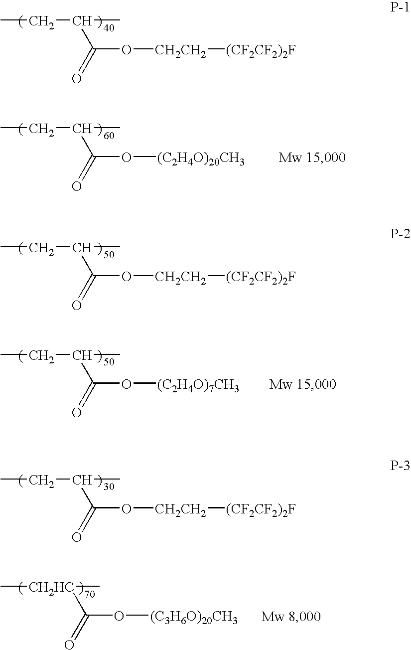


Re=(nx−ny)×d
Rth=[{(nx+ny)/2}−nz]×d
wherein nx and ny each is an in-plane refractive index of the transparent support, nz is a refractive index in the thickness direction of the transparent support, and d is a thickness of the transparent support.
Rth={(nx+ny)/2−nz}×d (I)
Re=(nx−ny)×d (II)
[wherein nx is a refractive index in the slow axis direction in the plane of film, ny is a refractive index in the fast axis in the plane of film, nz is a refractive index in the thickness direction of film, and d is a thickness of the film].
| Cellulose acetate having an | 100 parts by weight | ||
| acetylation degree of 60.9% | |||
| Triphenyl phosphate | 7.0 parts by weight | ||
| (plasticizer) | |||
| Biphenyldiphenyl phosphate | 4.0 parts by weight | ||
| (plasticizer) | |||
| Methylene chloride (first | 402.0 parts by weight | ||
| solvent) | |||
| Methanol (second solvent) | 60.0 parts by weight | ||
(Preparation of Matting Agent Solution)
| Silica particle having an | 2.0 parts by weight | ||
| average particle size of 16 nm | |||
| (AEROSIL R972, produced by | |||
| Nippon Aerosil Co., Ltd.) | |||
| Methylene chloride (first | 76.3 parts by weight | ||
| solvent) | |||
| Methanol (second solvent) | 11.4 parts by weight | ||
| Cellulose Acetate Solution A | 10.3 parts by weight | ||
(Preparation of Retardation Increasing Agent Solution)
| Retardation Increasing Agent I | 19.8 parts by weight | ||
| UV Absorbent (A) | 0.07 parts by weight | ||
| UV Absorbent (B) | 0.13 parts by weight | ||
| Methylene chloride (first | 58.4 parts by weight | ||
| solvent) | |||
| Methanol (second solvent) | 8.7 parts by weight | ||
| Cellulose Acetate Solution A | 12.8 parts by weight | ||
| Retardation Increasing Agent I: |
 |
| UV Absorbent: |
| UV Absorbent A: |
 |
| UV Absorbent B: |
 |
(Production of Cellulose Acetate Film)
| Isopropyl alcohol | 818 parts by weight | ||
| Water | 167 parts by weight | ||
| Propylene glycol | 187 parts by weight | ||
| Potassium hydroxide | 777 parts by weight | ||
<Composition B of Saponification Solution>
| Modified polyvinyl alcohol shown below | 20 parts by weight | ||
| Water | 360 parts by weight | ||
| Methanol | 120 parts by weight | ||
| Glutaraldehyde (crosslinking agent) | 1.0 part by weight | ||
| Modified Polyvinyl Alcohol: |
 |
(Formation of Optically Anisotropic Layer)

Production of Optical Compensating Sheets 2 to 7:
| Surface active agent | 0.15 | parts by weight | ||
| Methyl ethyl ketone | 1,000 | parts by weight | ||
| TABLE 1 | ||||
| Species of | Amount of | |||
| Optical | Surface | Surface Active | Layer to | |
| Compensating | Active | Agent Coated | Which | |
| Sheet | Agent | (g/m2) | Added | Remarks |
| 1 | none | none | none | Comparison |
| 2 | FS-21 | 0.003 | optically | ″ |
| anisotropic | ||||
| layer | ||||
| 3 | P-1 | ″ | ″ | ″ |
| 4 | P-24 | ″ | ″ | ″ |
| 5 | P-32 | ″ | ″ | ″ |
| 6 | P-64 | ″ | ″ | ″ |
| 7 | P-69 | ″ | ″ | ″ |
| 8 | FS-21 | ″ | upper layer | Invention |
| 9 | P-1 | ″ | ″ | ″ |
| 10 | P-24 | ″ | ″ | ″ |
| 11 | P-32 | ″ | ″ | ″ |
| 12 | P-64 | ″ | ″ | ″ |
| 13 | P-69 | ″ | ″ | ″ |


| TABLE 2 | ||||
| Optical | ||||
| Compensating | Maximum | Minimum | Standard | |
| Sheet | Value (nm) | Value (nm) | Deviation | Remarks |
| 1 | 43.2 | 21.7 | 10.3 | Comparison |
| 2 | 41.3 | 23.5 | 9.1 | ″ |
| 3 | 40.9 | 23.3 | 8.7 | ″ |
| 4 | 37.3 | 29.7 | 7.7 | ″ |
| 5 | 37.9 | 28.9 | 7.2 | ″ |
| 6 | 38.0 | 29.1 | 7.6 | ″ |
| 7 | 38.5 | 29.8 | 5.2 | ″ |
| 8 | 34.7 | 31.6 | 3.1 | Invention |
| 9 | 33.2 | 30.8 | 2.8 | ″ |
| 10 | 33.5 | 31.0 | 2.6 | ″ |
| 11 | 33.9 | 30.5 | 3.0 | ″ |
| 12 | 34.1 | 31.2 | 2.7 | ″ |
| 13 | 34.0 | 31.4 | 2.5 | ″ |
(Production of Elliptically Polarizing Plate)
| Cellulose acetate having an | 100 parts by weight | ||
| acetylation degree of 60.9% | |||
| Triphenyl phosphate | 7.0 parts by weight | ||
| (plasticizer) | |||
| Biphenyldiphenyl phosphate | 4.0 parts by weight | ||
| (plasticizer) | |||
| Methylene chloride (first | 402.0 parts by weight | ||
| solvent) | |||
| Methanol (second solvent) | 60.0 parts by weight | ||
| Modified polyvinyl alcohol | 10 parts by weight | ||
| shown above | |||
| Water | 371 parts by weight | ||
| Methanol | 119 parts by weight | ||
| Glutaraldehyde (crosslinking | 0.5 part by weight | ||
| agent) | |||
(Formation of Optically Anisotropic Layer)
| Discotic liquid crystalline compound | 1.57 g/m2 | ||
| shown above | |||
| Ethylene oxide-modified | 0.156 g/m2 | ||
| trimethylolpropane triacrylate | |||
| (V#360, produced by Osaka Organic | |||
| Chemical Industry Ltd.) | |||
| Cellulose acetate butyrate (CAB551- | 0.0346 g/m2 | ||
| 0.2, produced by Eastman Chemical) | |||
| Cellulose acetate butyrate (CAB531-1, | 0.0088 g/m2 | ||
| produced by Eastman Chemical) | |||
| Photopolymerization initiator | 0.0518 g/m2 | ||
| (Irgacure 907, produced by Ciba- | |||
| Geigy) | |||
| Sensitizer (Kayacure DETX, produced | 0.0173 g/m2 | ||
| by Nippon Kayaku Co., Ltd.) | |||
Composition of Surface Active Agent Layer>
| Cellulose acetate having an | 80 parts by weight | ||
| acetylation degree of 60.9% | |||
| (linter) | |||
| Cellulose acetate having an | 20 parts by weight | ||
| acetylation degree of 60.8% | |||
| (linter) | |||
| Triphenyl phosphate | 7.8 parts by weight | ||
| (plasticizer) | |||
| Biphenyldiphenyl phosphate | 3.9 parts by weight | ||
| (plasticizer) | |||
| Methylene chloride (first | 300 parts by weight | ||
| solvent) | |||
| Methanol (second solvent) | 54 parts by weight | ||
| 1-Butanol (third solvent) | 11 parts by weight | ||

| Modified polyvinyl alcohol | 10 parts by weight | ||
| shown below | |||
| Water | 371 parts by weight | ||
| Methanol | 119 parts by weight | ||
| Glutaraldehyde (crosslinking | 0.5 part by weight | ||
| agent) | |||
| Modified Polyvinyl Alcohol: |
 |
| Modified polyvinyl alcohol of | 10 parts by weight | ||
| Example 3 | |||
| Water | 371 parts by weight | ||
| Methanol | 119 parts by weight | ||
| Glutaraldehyde (crosslinking | 0.5 part by weight | ||
| agent) | |||
| TABLE 3 | ||
| View Angle (range having contrast | ||
| ratio of 10 or more and free from | ||
| Glay scale inversion) | ||
| Liquid Crystal Display Device | Upward | Downward | Right and Left |
| Example 3 | 80° | 80° | 80° |
| Comparative Example 1 | 80° | 80° | 80° |
| (Note) | |||
| Gradation reversal in black side: | |||
| Occurrence of Glay scale inversion between L1 and L2. | |||
| TABLE 4 | ||
| View Angle (range having contrast | ||
| ratio of 10 or more and free from | ||
| gradation reversal in black side) | ||
| Liquid Crystal Display Device | Upward | Downward | Right and Left |
| Example 4 | 80° | 60° | 80° |
| Comparative Example 2 | 80° | 45° | 80° |
| (Note) | |||
| Gradation reversal in black side: | |||
| Occurrence of gradation reversal between L1 and L2. | |||
(Evaluation of Unevenness on Panel of Liquid Crystal Display Device)
| Modified polyvinyl alcohol of | 10 parts by weight | ||
| Example 3 | |||
| Water | 371 parts by weight | ||
| Methanol | 119 parts by weight | ||
| Glutaraldehyde (crosslinking | 0.5 part by weight | ||
| agent) | |||
Claims (18)


Applications Claiming Priority (5)
| Application Number | Priority Date | Filing Date | Title |
|---|---|---|---|
| JP2002364034A JP4190275B2 (en) | 2002-12-16 | 2002-12-16 | Optical film, polarizing plate and liquid crystal display device using the same |
| JP2002-364034 | 2002-12-16 | ||
| JP2003085455A JP4241130B2 (en) | 2003-03-26 | 2003-03-26 | Optical compensation sheet, manufacturing method thereof, polarizing plate, and liquid crystal display device |
| JP2003-085455 | 2003-03-26 | ||
| PCT/JP2003/016128 WO2004055558A1 (en) | 2002-12-16 | 2003-12-16 | Optical compensating sheet, production method thereof, optical film, and polarizing plate and liquid crystal display device using the same |
Publications (2)
| Publication Number | Publication Date |
|---|---|
| US20060040070A1 US20060040070A1 (en) | 2006-02-23 |
| US7462382B2 true US7462382B2 (en) | 2008-12-09 |
Family
ID=32599265
Family Applications (1)
| Application Number | Title | Priority Date | Filing Date |
|---|---|---|---|
| US10/535,248 Active 2024-09-18 US7462382B2 (en) | 2002-12-16 | 2003-12-16 | Optical compensating sheet, production method thereof, optical film, and polarizing plate and liquid crystal display device using the same |
Country Status (8)
| Country | Link |
|---|---|
| US (1) | US7462382B2 (en) |
| EP (1) | EP1573373B1 (en) |
| KR (1) | KR101023005B1 (en) |
| AT (1) | ATE392635T1 (en) |
| AU (1) | AU2003288751A1 (en) |
| DE (1) | DE60320451T2 (en) |
| TW (1) | TWI309726B (en) |
| WO (1) | WO2004055558A1 (en) |
Cited By (5)
| Publication number | Priority date | Publication date | Assignee | Title |
|---|---|---|---|---|
| US9068063B2 (en) | 2010-06-29 | 2015-06-30 | Eastman Chemical Company | Cellulose ester/elastomer compositions |
| US9273195B2 (en) | 2010-06-29 | 2016-03-01 | Eastman Chemical Company | Tires comprising cellulose ester/elastomer compositions |
| US9708475B2 (en) | 2011-12-07 | 2017-07-18 | Eastman Chemical Company | Cellulose esters in highly-filled elastomeric systems |
| US10077342B2 (en) | 2016-01-21 | 2018-09-18 | Eastman Chemical Company | Elastomeric compositions comprising cellulose ester additives |
| US11230669B2 (en) * | 2017-07-03 | 2022-01-25 | Fujifilm Corporation | Liquid crystal film, optical laminate, circularly polarizing plate, and organic electroluminescent display device |
Families Citing this family (13)
| Publication number | Priority date | Publication date | Assignee | Title |
|---|---|---|---|---|
| JP4786552B2 (en) * | 2004-06-25 | 2011-10-05 | 富士フイルム株式会社 | Optical compensation sheet, manufacturing method thereof, polarizing plate and liquid crystal display device using the same |
| TWI263848B (en) * | 2004-09-07 | 2006-10-11 | Optimax Tech Corp | An optical sheet for a super twisted nematic display |
| WO2007026591A1 (en) * | 2005-08-30 | 2007-03-08 | Konica Minolta Opto, Inc. | Optical film and method for manufacturing same, polarizing plate using same, and liquid crystal display |
| US20070098920A1 (en) * | 2005-09-30 | 2007-05-03 | Fujifilm Corporation | Optical film, polarizing plate and liquid crystal display |
| TWI406899B (en) * | 2006-09-05 | 2013-09-01 | Tosoh Corp | Optical compensation film and phase difference film |
| JP4993351B2 (en) * | 2007-02-23 | 2012-08-08 | 富士フイルム株式会社 | Optical film manufacturing method and optical film |
| TWI488933B (en) * | 2008-02-01 | 2015-06-21 | Lg Chemical Ltd | Acrylic pressure-sensitive adhesive composition comprising optical anisotropic compound, polarizer and liquid crystal display device comprising the same |
| KR101133064B1 (en) * | 2008-04-25 | 2012-04-04 | 주식회사 엘지화학 | An acrylic pressure-sensitive adhesive composition, a polarizer and a liquid crystal display device comprising the same |
| WO2010002195A2 (en) * | 2008-07-01 | 2010-01-07 | (주)Lg화학 | Adhesive composition, polarizing plate, and liquid crystal display |
| US20120256878A1 (en) * | 2009-12-24 | 2012-10-11 | Nissha Printing Co., Ltd. | Capacitive touch sensor, electronic device, and method of manufacturing transparent conductive-film laminate |
| KR101772423B1 (en) * | 2013-05-02 | 2017-08-29 | 후지필름 가부시키가이샤 | Transfer film and optical film |
| KR102177052B1 (en) * | 2013-08-09 | 2020-11-10 | 스미또모 가가꾸 가부시키가이샤 | Process for producing optical anisotropic laminate |
| KR102162891B1 (en) * | 2013-12-31 | 2020-10-08 | 엘지디스플레이 주식회사 | Liquid crystal composition and liquid crystal display device having the same |
Citations (23)
| Publication number | Priority date | Publication date | Assignee | Title |
|---|---|---|---|---|
| EP0537779A1 (en) | 1991-10-17 | 1993-04-21 | Fuji Photo Film Co., Ltd. | Coating method |
| JPH07136578A (en) | 1993-11-12 | 1995-05-30 | Dainippon Printing Co Ltd | Simultaneous multilayer coating method |
| US5624974A (en) * | 1994-12-28 | 1997-04-29 | Sharp Kabushiki Kaisha | Photopolymerizable resin material composition comprising fluorinated (meth)acrylates |
| EP0911656A2 (en) | 1997-10-20 | 1999-04-28 | Fuji Photo Film Co., Ltd. | Optical compensatory sheet and liquid crystal display |
| JPH11148080A (en) | 1997-11-18 | 1999-06-02 | Dainippon Ink & Chem Inc | Polymerizable liquid crystal composition and optical isomer comprising the same composition |
| JP2000009936A (en) | 1998-06-22 | 2000-01-14 | Fuji Photo Film Co Ltd | Production of optical compensation sheet |
| US6151169A (en) | 1998-05-20 | 2000-11-21 | Lg Electronics, Inc. | Sheet type optical device and backlighting unit using the same |
| EP1079244A2 (en) | 1999-08-23 | 2001-02-28 | Fuji Photo Film Co., Ltd. | Orientation layer containing (meth)acrylic copolymer having hydrophobic repeating units |
| TW451078B (en) | 1999-09-13 | 2001-08-21 | Nitto Denko Corp | Optically compensatory film, optically compensatory polarizing plate and liquid-crystal display device |
| TW451071B (en) | 1999-09-22 | 2001-08-21 | Nitto Denko Corp | Composite retarder plate, optically compensatory polarizing plate and liquid-crystal display device |
| JP2001330725A (en) | 2000-05-18 | 2001-11-30 | Fuji Photo Film Co Ltd | Optical compensation sheet, elliptically polarizing plate and liquid crystal display device |
| JP2002071949A (en) | 2000-09-01 | 2002-03-12 | Fuji Photo Film Co Ltd | Optical compensation sheet, polarizing plate and liquid crystal display device using the same |
| JP2002071955A (en) | 2000-09-05 | 2002-03-12 | Fuji Photo Film Co Ltd | Optical compensating sheet, polarizing plate and liquid crystal display |
| US20020048639A1 (en) * | 2000-03-29 | 2002-04-25 | Masayuki Negoro | Process for orienting rod-like liquid crystal molecules |
| JP2002236215A (en) | 2000-12-04 | 2002-08-23 | Fuji Photo Film Co Ltd | Optical compensation sheet, elliptically polarizing plate and liquid crystal display device |
| EP1235106A2 (en) | 2001-02-08 | 2002-08-28 | Fuji Photo Film Co., Ltd. | Lithographic printing plate precursor |
| JP2002311577A (en) | 2001-02-08 | 2002-10-23 | Fuji Photo Film Co Ltd | Original plate of planographic printing plate |
| US6476892B2 (en) | 2000-03-02 | 2002-11-05 | Fuji Photo Film Co., Ltd. | Optical compensatory sheet consisting of one cellulose acetate film |
| US20020168511A1 (en) * | 2001-05-14 | 2002-11-14 | Kent State University | Alignment of lyotropic chromonic liquid crystals at surfaces as monolayers and multilayered stacks |
| US20040036828A1 (en) | 2000-12-04 | 2004-02-26 | Eiichiro Aminaka | Optical compensating sheet having optically anisotropic layer made of discotic liquid-crystalline molecules and transparent substrate comprising polymer film |
| US7052745B2 (en) * | 2000-03-29 | 2006-05-30 | Fuji Photo Film Co., Ltd. | Optically anisotropic sheet comprising aligned discotic liquid crystal molecules |
| US7105270B2 (en) * | 2002-01-31 | 2006-09-12 | Fuji Photo Film Co., Ltd. | Fluoroaliphatic group-containing copolymer |
| US20070132139A1 (en) | 2000-12-04 | 2007-06-14 | Fuji Photo Film Co., Ltd. | Process for preparation of optically anisotropic cellulose ester film |
-
2003
- 2003-12-15 TW TW092135331A patent/TWI309726B/en not_active IP Right Cessation
- 2003-12-16 AT AT03780806T patent/ATE392635T1/en not_active IP Right Cessation
- 2003-12-16 EP EP03780806A patent/EP1573373B1/en not_active Expired - Lifetime
- 2003-12-16 US US10/535,248 patent/US7462382B2/en active Active
- 2003-12-16 DE DE60320451T patent/DE60320451T2/en not_active Expired - Lifetime
- 2003-12-16 WO PCT/JP2003/016128 patent/WO2004055558A1/en active IP Right Grant
- 2003-12-16 KR KR1020057011142A patent/KR101023005B1/en active IP Right Grant
- 2003-12-16 AU AU2003288751A patent/AU2003288751A1/en not_active Abandoned
Patent Citations (27)
| Publication number | Priority date | Publication date | Assignee | Title |
|---|---|---|---|---|
| EP0537779A1 (en) | 1991-10-17 | 1993-04-21 | Fuji Photo Film Co., Ltd. | Coating method |
| JPH05127305A (en) | 1991-10-17 | 1993-05-25 | Fuji Photo Film Co Ltd | Method of application |
| US5498510A (en) | 1991-10-17 | 1996-03-12 | Fuji Photo Film Co., Ltd. | Method for simultaneously coating at least two layers to make a photographic light-sensitive element |
| JPH07136578A (en) | 1993-11-12 | 1995-05-30 | Dainippon Printing Co Ltd | Simultaneous multilayer coating method |
| US5624974A (en) * | 1994-12-28 | 1997-04-29 | Sharp Kabushiki Kaisha | Photopolymerizable resin material composition comprising fluorinated (meth)acrylates |
| EP0911656A2 (en) | 1997-10-20 | 1999-04-28 | Fuji Photo Film Co., Ltd. | Optical compensatory sheet and liquid crystal display |
| JPH11148080A (en) | 1997-11-18 | 1999-06-02 | Dainippon Ink & Chem Inc | Polymerizable liquid crystal composition and optical isomer comprising the same composition |
| US6151169A (en) | 1998-05-20 | 2000-11-21 | Lg Electronics, Inc. | Sheet type optical device and backlighting unit using the same |
| JP2000009936A (en) | 1998-06-22 | 2000-01-14 | Fuji Photo Film Co Ltd | Production of optical compensation sheet |
| EP1079244A2 (en) | 1999-08-23 | 2001-02-28 | Fuji Photo Film Co., Ltd. | Orientation layer containing (meth)acrylic copolymer having hydrophobic repeating units |
| TW451078B (en) | 1999-09-13 | 2001-08-21 | Nitto Denko Corp | Optically compensatory film, optically compensatory polarizing plate and liquid-crystal display device |
| US6417904B1 (en) | 1999-09-13 | 2002-07-09 | Nitto Denko Corporation | Optically compensatory film, optically compensatory polarizing plate and liquid-crystal display device |
| TW451071B (en) | 1999-09-22 | 2001-08-21 | Nitto Denko Corp | Composite retarder plate, optically compensatory polarizing plate and liquid-crystal display device |
| US6330108B1 (en) | 1999-09-22 | 2001-12-11 | Nitto Denko Corporation | Composite retarder plate, optically compensatory polarizing plate and liquid-crystal display device |
| US6476892B2 (en) | 2000-03-02 | 2002-11-05 | Fuji Photo Film Co., Ltd. | Optical compensatory sheet consisting of one cellulose acetate film |
| US7052745B2 (en) * | 2000-03-29 | 2006-05-30 | Fuji Photo Film Co., Ltd. | Optically anisotropic sheet comprising aligned discotic liquid crystal molecules |
| US20020048639A1 (en) * | 2000-03-29 | 2002-04-25 | Masayuki Negoro | Process for orienting rod-like liquid crystal molecules |
| JP2001330725A (en) | 2000-05-18 | 2001-11-30 | Fuji Photo Film Co Ltd | Optical compensation sheet, elliptically polarizing plate and liquid crystal display device |
| JP2002071949A (en) | 2000-09-01 | 2002-03-12 | Fuji Photo Film Co Ltd | Optical compensation sheet, polarizing plate and liquid crystal display device using the same |
| JP2002071955A (en) | 2000-09-05 | 2002-03-12 | Fuji Photo Film Co Ltd | Optical compensating sheet, polarizing plate and liquid crystal display |
| JP2002236215A (en) | 2000-12-04 | 2002-08-23 | Fuji Photo Film Co Ltd | Optical compensation sheet, elliptically polarizing plate and liquid crystal display device |
| US20040036828A1 (en) | 2000-12-04 | 2004-02-26 | Eiichiro Aminaka | Optical compensating sheet having optically anisotropic layer made of discotic liquid-crystalline molecules and transparent substrate comprising polymer film |
| US20070132139A1 (en) | 2000-12-04 | 2007-06-14 | Fuji Photo Film Co., Ltd. | Process for preparation of optically anisotropic cellulose ester film |
| EP1235106A2 (en) | 2001-02-08 | 2002-08-28 | Fuji Photo Film Co., Ltd. | Lithographic printing plate precursor |
| JP2002311577A (en) | 2001-02-08 | 2002-10-23 | Fuji Photo Film Co Ltd | Original plate of planographic printing plate |
| US20020168511A1 (en) * | 2001-05-14 | 2002-11-14 | Kent State University | Alignment of lyotropic chromonic liquid crystals at surfaces as monolayers and multilayered stacks |
| US7105270B2 (en) * | 2002-01-31 | 2006-09-12 | Fuji Photo Film Co., Ltd. | Fluoroaliphatic group-containing copolymer |
Non-Patent Citations (1)
| Title |
|---|
| JPO Website Machine English Translation of JP2001-330725A, Ogawa, Nov. 30, 2001. * |
Cited By (10)
| Publication number | Priority date | Publication date | Assignee | Title |
|---|---|---|---|---|
| US9068063B2 (en) | 2010-06-29 | 2015-06-30 | Eastman Chemical Company | Cellulose ester/elastomer compositions |
| US9200147B2 (en) | 2010-06-29 | 2015-12-01 | Eastman Chemical Company | Processes for making cellulose ester compositions |
| US9273195B2 (en) | 2010-06-29 | 2016-03-01 | Eastman Chemical Company | Tires comprising cellulose ester/elastomer compositions |
| US9708475B2 (en) | 2011-12-07 | 2017-07-18 | Eastman Chemical Company | Cellulose esters in highly-filled elastomeric systems |
| US9708474B2 (en) | 2011-12-07 | 2017-07-18 | Eastman Chemical Company | Cellulose esters in pneumatic tires |
| US9708473B2 (en) | 2011-12-07 | 2017-07-18 | Eastman Chemical Company | Cellulose esters in pneumatic tires |
| US9708472B2 (en) | 2011-12-07 | 2017-07-18 | Eastman Chemical Company | Cellulose esters in highly-filled elastomeric systems |
| US10077342B2 (en) | 2016-01-21 | 2018-09-18 | Eastman Chemical Company | Elastomeric compositions comprising cellulose ester additives |
| US10077343B2 (en) | 2016-01-21 | 2018-09-18 | Eastman Chemical Company | Process to produce elastomeric compositions comprising cellulose ester additives |
| US11230669B2 (en) * | 2017-07-03 | 2022-01-25 | Fujifilm Corporation | Liquid crystal film, optical laminate, circularly polarizing plate, and organic electroluminescent display device |
Also Published As
| Publication number | Publication date |
|---|---|
| WO2004055558A1 (en) | 2004-07-01 |
| DE60320451D1 (en) | 2008-05-29 |
| DE60320451T2 (en) | 2009-05-07 |
| EP1573373A4 (en) | 2006-06-07 |
| ATE392635T1 (en) | 2008-05-15 |
| KR101023005B1 (en) | 2011-03-22 |
| TWI309726B (en) | 2009-05-11 |
| US20060040070A1 (en) | 2006-02-23 |
| EP1573373B1 (en) | 2008-04-16 |
| KR20050085714A (en) | 2005-08-29 |
| EP1573373A1 (en) | 2005-09-14 |
| TW200420902A (en) | 2004-10-16 |
| AU2003288751A1 (en) | 2004-07-09 |
Similar Documents
| Publication | Publication Date | Title |
|---|---|---|
| US7462382B2 (en) | Optical compensating sheet, production method thereof, optical film, and polarizing plate and liquid crystal display device using the same | |
| US8524116B2 (en) | Optical compensatory film, process for producing the same, and polarizing plate and liquid crystal display employing the same | |
| JP4284221B2 (en) | Liquid crystal display | |
| KR20040005840A (en) | Cellulose acetate film with regulated retardation and thickness | |
| EP1615056A2 (en) | Polarizing plate | |
| JP4190275B2 (en) | Optical film, polarizing plate and liquid crystal display device using the same | |
| JP2007156459A (en) | Optical film, polarizing plate, and liquid crystal display device | |
| JP4993351B2 (en) | Optical film manufacturing method and optical film | |
| KR101264426B1 (en) | Producing method of optical compensation film optical compensation film polarizing plate and liquid crystal display | |
| JP2006276643A (en) | Phase difference film, and liquid crystal display and compound | |
| JP2005206638A (en) | Optical film and polarizing plate and picture display unit using the same | |
| KR20080072843A (en) | Optical film, polarizing plate and liquid crystal display device | |
| JP2006267183A (en) | Optical compensation sheet, its manufacturing method, polarizing plate and liquid crystal display using the same | |
| JP2008197170A (en) | Manufacturing method of optical film, optical film, optical compensation sheet, polarizing plate and liquid crystal display apparatus using the optical film | |
| JP2009098642A (en) | Laminated optical film, polarizing plate and liquid crystal display device | |
| KR20060101346A (en) | Optical compensation film, polarizing plate and liquid crystal display | |
| US7787084B2 (en) | Optical compensation film, polarizing plate and liquid crystal display device | |
| US20070098920A1 (en) | Optical film, polarizing plate and liquid crystal display | |
| US20070002232A1 (en) | Optical compensation film, polarizing plate and liquid crystal display device | |
| JP2007122043A (en) | Optical film, polarizing plate using same, and liquid crystal display device | |
| JP4241130B2 (en) | Optical compensation sheet, manufacturing method thereof, polarizing plate, and liquid crystal display device | |
| JP2004333852A (en) | Optical film, polarizing plate and liquid crystal display | |
| JP2006267628A (en) | Optical film and polarizing plate and liquid crystal display apparatus using the same | |
| JP2009086378A (en) | Optical compensation film, polarizing plate and liquid crystal display | |
| JP2007241125A (en) | Optical compensating film and method of manufacturing same, and polarizing plate using same, and liquid crystal display device |
Legal Events
| Date | Code | Title | Description |
|---|---|---|---|
| AS | Assignment |
Owner name: FUJI PHOTO FILM CO., LTD., JAPAN Free format text: ASSIGNMENT OF ASSIGNORS INTEREST;ASSIGNORS:ITO, YOJI;YASUDA, TOMOKAZU;FUKAGAWA, NOBUTAKA;AND OTHERS;REEL/FRAME:017016/0489 Effective date: 20050415 |
|
| AS | Assignment |
Owner name: FUJIFILM HOLDINGS CORPORATION, JAPAN Free format text: CHANGE OF NAME AS SHOWN BY THE ATTACHED CERTIFICATE OF PARTIAL CLOSED RECORDS AND THE VERIFIED ENGLISH TRANSLATION THEREOF;ASSIGNOR:FUJI PHOTO FILM CO., LTD.;REEL/FRAME:018942/0958 Effective date: 20061001 Owner name: FUJIFILM HOLDINGS CORPORATION,JAPAN Free format text: CHANGE OF NAME AS SHOWN BY THE ATTACHED CERTIFICATE OF PARTIAL CLOSED RECORDS AND THE VERIFIED ENGLISH TRANSLATION THEREOF;ASSIGNOR:FUJI PHOTO FILM CO., LTD.;REEL/FRAME:018942/0958 Effective date: 20061001 |
|
| AS | Assignment |
Owner name: FUJIFILM CORPORATION, JAPAN Free format text: ASSIGNMENT OF ASSIGNORS INTEREST;ASSIGNOR:FUJIFILM HOLDINGS CORPORATION;REEL/FRAME:019193/0322 Effective date: 20070315 Owner name: FUJIFILM CORPORATION,JAPAN Free format text: ASSIGNMENT OF ASSIGNORS INTEREST;ASSIGNOR:FUJIFILM HOLDINGS CORPORATION;REEL/FRAME:019193/0322 Effective date: 20070315 |
|
| FEPP | Fee payment procedure |
Free format text: PAYOR NUMBER ASSIGNED (ORIGINAL EVENT CODE: ASPN); ENTITY STATUS OF PATENT OWNER: LARGE ENTITY |
|
| STCF | Information on status: patent grant |
Free format text: PATENTED CASE |
|
| FPAY | Fee payment |
Year of fee payment: 4 |
|
| FPAY | Fee payment |
Year of fee payment: 8 |
|
| MAFP | Maintenance fee payment |
Free format text: PAYMENT OF MAINTENANCE FEE, 12TH YEAR, LARGE ENTITY (ORIGINAL EVENT CODE: M1553); ENTITY STATUS OF PATENT OWNER: LARGE ENTITY Year of fee payment: 12 |