US7463182B1 - Radar apparatus - Google Patents
Radar apparatus Download PDFInfo
- Publication number
- US7463182B1 US7463182B1 US11/483,100 US48310006A US7463182B1 US 7463182 B1 US7463182 B1 US 7463182B1 US 48310006 A US48310006 A US 48310006A US 7463182 B1 US7463182 B1 US 7463182B1
- Authority
- US
- United States
- Prior art keywords
- moving object
- radar apparatus
- detected
- width
- unit
- Prior art date
- Legal status (The legal status is an assumption and is not a legal conclusion. Google has not performed a legal analysis and makes no representation as to the accuracy of the status listed.)
- Expired - Fee Related, expires
Links
Images


Classifications
-
- G—PHYSICS
- G01—MEASURING; TESTING
- G01S—RADIO DIRECTION-FINDING; RADIO NAVIGATION; DETERMINING DISTANCE OR VELOCITY BY USE OF RADIO WAVES; LOCATING OR PRESENCE-DETECTING BY USE OF THE REFLECTION OR RERADIATION OF RADIO WAVES; ANALOGOUS ARRANGEMENTS USING OTHER WAVES
- G01S13/00—Systems using the reflection or reradiation of radio waves, e.g. radar systems; Analogous systems using reflection or reradiation of waves whose nature or wavelength is irrelevant or unspecified
- G01S13/88—Radar or analogous systems specially adapted for specific applications
- G01S13/93—Radar or analogous systems specially adapted for specific applications for anti-collision purposes
- G01S13/931—Radar or analogous systems specially adapted for specific applications for anti-collision purposes of land vehicles
-
- G—PHYSICS
- G01—MEASURING; TESTING
- G01S—RADIO DIRECTION-FINDING; RADIO NAVIGATION; DETERMINING DISTANCE OR VELOCITY BY USE OF RADIO WAVES; LOCATING OR PRESENCE-DETECTING BY USE OF THE REFLECTION OR RERADIATION OF RADIO WAVES; ANALOGOUS ARRANGEMENTS USING OTHER WAVES
- G01S13/00—Systems using the reflection or reradiation of radio waves, e.g. radar systems; Analogous systems using reflection or reradiation of waves whose nature or wavelength is irrelevant or unspecified
- G01S13/02—Systems using reflection of radio waves, e.g. primary radar systems; Analogous systems
- G01S13/06—Systems determining position data of a target
- G01S13/08—Systems for measuring distance only
- G01S13/32—Systems for measuring distance only using transmission of continuous waves, whether amplitude-, frequency-, or phase-modulated, or unmodulated
- G01S13/36—Systems for measuring distance only using transmission of continuous waves, whether amplitude-, frequency-, or phase-modulated, or unmodulated with phase comparison between the received signal and the contemporaneously transmitted signal
- G01S13/38—Systems for measuring distance only using transmission of continuous waves, whether amplitude-, frequency-, or phase-modulated, or unmodulated with phase comparison between the received signal and the contemporaneously transmitted signal wherein more than one modulation frequency is used
-
- G—PHYSICS
- G01—MEASURING; TESTING
- G01S—RADIO DIRECTION-FINDING; RADIO NAVIGATION; DETERMINING DISTANCE OR VELOCITY BY USE OF RADIO WAVES; LOCATING OR PRESENCE-DETECTING BY USE OF THE REFLECTION OR RERADIATION OF RADIO WAVES; ANALOGOUS ARRANGEMENTS USING OTHER WAVES
- G01S13/00—Systems using the reflection or reradiation of radio waves, e.g. radar systems; Analogous systems using reflection or reradiation of waves whose nature or wavelength is irrelevant or unspecified
- G01S13/02—Systems using reflection of radio waves, e.g. primary radar systems; Analogous systems
- G01S13/06—Systems determining position data of a target
- G01S13/42—Simultaneous measurement of distance and other co-ordinates
- G01S13/44—Monopulse radar, i.e. simultaneous lobing
- G01S13/4445—Monopulse radar, i.e. simultaneous lobing amplitude comparisons monopulse, i.e. comparing the echo signals received by an antenna arrangement with overlapping squinted beams
-
- G—PHYSICS
- G01—MEASURING; TESTING
- G01S—RADIO DIRECTION-FINDING; RADIO NAVIGATION; DETERMINING DISTANCE OR VELOCITY BY USE OF RADIO WAVES; LOCATING OR PRESENCE-DETECTING BY USE OF THE REFLECTION OR RERADIATION OF RADIO WAVES; ANALOGOUS ARRANGEMENTS USING OTHER WAVES
- G01S13/00—Systems using the reflection or reradiation of radio waves, e.g. radar systems; Analogous systems using reflection or reradiation of waves whose nature or wavelength is irrelevant or unspecified
- G01S13/02—Systems using reflection of radio waves, e.g. primary radar systems; Analogous systems
- G01S13/50—Systems of measurement based on relative movement of target
- G01S13/52—Discriminating between fixed and moving objects or between objects moving at different speeds
- G01S13/536—Discriminating between fixed and moving objects or between objects moving at different speeds using transmission of continuous unmodulated waves, amplitude-, frequency-, or phase-modulated waves
-
- G—PHYSICS
- G01—MEASURING; TESTING
- G01S—RADIO DIRECTION-FINDING; RADIO NAVIGATION; DETERMINING DISTANCE OR VELOCITY BY USE OF RADIO WAVES; LOCATING OR PRESENCE-DETECTING BY USE OF THE REFLECTION OR RERADIATION OF RADIO WAVES; ANALOGOUS ARRANGEMENTS USING OTHER WAVES
- G01S7/00—Details of systems according to groups G01S13/00, G01S15/00, G01S17/00
- G01S7/02—Details of systems according to groups G01S13/00, G01S15/00, G01S17/00 of systems according to group G01S13/00
- G01S7/41—Details of systems according to groups G01S13/00, G01S15/00, G01S17/00 of systems according to group G01S13/00 using analysis of echo signal for target characterisation; Target signature; Target cross-section
- G01S7/415—Identification of targets based on measurements of movement associated with the target
-
- G—PHYSICS
- G01—MEASURING; TESTING
- G01S—RADIO DIRECTION-FINDING; RADIO NAVIGATION; DETERMINING DISTANCE OR VELOCITY BY USE OF RADIO WAVES; LOCATING OR PRESENCE-DETECTING BY USE OF THE REFLECTION OR RERADIATION OF RADIO WAVES; ANALOGOUS ARRANGEMENTS USING OTHER WAVES
- G01S13/00—Systems using the reflection or reradiation of radio waves, e.g. radar systems; Analogous systems using reflection or reradiation of waves whose nature or wavelength is irrelevant or unspecified
- G01S13/02—Systems using reflection of radio waves, e.g. primary radar systems; Analogous systems
- G01S13/50—Systems of measurement based on relative movement of target
- G01S13/58—Velocity or trajectory determination systems; Sense-of-movement determination systems
- G01S13/583—Velocity or trajectory determination systems; Sense-of-movement determination systems using transmission of continuous unmodulated waves, amplitude-, frequency-, or phase-modulated waves and based upon the Doppler effect resulting from movement of targets
- G01S13/584—Velocity or trajectory determination systems; Sense-of-movement determination systems using transmission of continuous unmodulated waves, amplitude-, frequency-, or phase-modulated waves and based upon the Doppler effect resulting from movement of targets adapted for simultaneous range and velocity measurements
-
- G—PHYSICS
- G01—MEASURING; TESTING
- G01S—RADIO DIRECTION-FINDING; RADIO NAVIGATION; DETERMINING DISTANCE OR VELOCITY BY USE OF RADIO WAVES; LOCATING OR PRESENCE-DETECTING BY USE OF THE REFLECTION OR RERADIATION OF RADIO WAVES; ANALOGOUS ARRANGEMENTS USING OTHER WAVES
- G01S13/00—Systems using the reflection or reradiation of radio waves, e.g. radar systems; Analogous systems using reflection or reradiation of waves whose nature or wavelength is irrelevant or unspecified
- G01S13/88—Radar or analogous systems specially adapted for specific applications
- G01S13/886—Radar or analogous systems specially adapted for specific applications for alarm systems
-
- G—PHYSICS
- G01—MEASURING; TESTING
- G01S—RADIO DIRECTION-FINDING; RADIO NAVIGATION; DETERMINING DISTANCE OR VELOCITY BY USE OF RADIO WAVES; LOCATING OR PRESENCE-DETECTING BY USE OF THE REFLECTION OR RERADIATION OF RADIO WAVES; ANALOGOUS ARRANGEMENTS USING OTHER WAVES
- G01S13/00—Systems using the reflection or reradiation of radio waves, e.g. radar systems; Analogous systems using reflection or reradiation of waves whose nature or wavelength is irrelevant or unspecified
- G01S13/88—Radar or analogous systems specially adapted for specific applications
- G01S13/93—Radar or analogous systems specially adapted for specific applications for anti-collision purposes
- G01S13/931—Radar or analogous systems specially adapted for specific applications for anti-collision purposes of land vehicles
- G01S2013/9327—Sensor installation details
- G01S2013/93271—Sensor installation details in the front of the vehicles
-
- G—PHYSICS
- G01—MEASURING; TESTING
- G01S—RADIO DIRECTION-FINDING; RADIO NAVIGATION; DETERMINING DISTANCE OR VELOCITY BY USE OF RADIO WAVES; LOCATING OR PRESENCE-DETECTING BY USE OF THE REFLECTION OR RERADIATION OF RADIO WAVES; ANALOGOUS ARRANGEMENTS USING OTHER WAVES
- G01S13/00—Systems using the reflection or reradiation of radio waves, e.g. radar systems; Analogous systems using reflection or reradiation of waves whose nature or wavelength is irrelevant or unspecified
- G01S13/88—Radar or analogous systems specially adapted for specific applications
- G01S13/93—Radar or analogous systems specially adapted for specific applications for anti-collision purposes
- G01S13/931—Radar or analogous systems specially adapted for specific applications for anti-collision purposes of land vehicles
- G01S2013/9327—Sensor installation details
- G01S2013/93272—Sensor installation details in the back of the vehicles
-
- G—PHYSICS
- G01—MEASURING; TESTING
- G01S—RADIO DIRECTION-FINDING; RADIO NAVIGATION; DETERMINING DISTANCE OR VELOCITY BY USE OF RADIO WAVES; LOCATING OR PRESENCE-DETECTING BY USE OF THE REFLECTION OR RERADIATION OF RADIO WAVES; ANALOGOUS ARRANGEMENTS USING OTHER WAVES
- G01S13/00—Systems using the reflection or reradiation of radio waves, e.g. radar systems; Analogous systems using reflection or reradiation of waves whose nature or wavelength is irrelevant or unspecified
- G01S13/88—Radar or analogous systems specially adapted for specific applications
- G01S13/93—Radar or analogous systems specially adapted for specific applications for anti-collision purposes
- G01S13/931—Radar or analogous systems specially adapted for specific applications for anti-collision purposes of land vehicles
- G01S2013/9327—Sensor installation details
- G01S2013/93274—Sensor installation details on the side of the vehicles
Definitions
- the present invention relates a radar apparatus, and more specifically to a radar apparatus suitable for use in a surveillance radar apparatus that detects an object existing within a predetermined area and monitors the movement of the same.
- JP 2000-338231 A describes an art related to a radar apparatus that detects an intruding object by utilizing a radiowave such as microwave.
- JP 2002-236171 A discloses a radar system that detects an intruding object, and determines whether the intruding object is a human body or not, based on the radar cross section calculated from the signal power.
- JP 1999-183612 A describes a vehicle-mounted radar system, a signal processing circuit of which determines a distribution of the wave reflection points, and measures the position and width of a target based on the distribution.
- JP 2004-239744 A discloses a vehicle-mounted radar system that allows measurement of the width of a detected object.
- an infrared-based sensor wherein a transmitter and a receiver are installed in a linear monitoring area and blocking of the infrared light to the receiver is detected, but this sensor had a problem that a flying object such as a leave and snow is erroneously detected.
- a detection apparatus that employs, as a sensor, a radar which is less subject to surrounding environment, and measures the position and velocity of an intruding object.
- a radar which is less subject to surrounding environment, and measures the position and velocity of an intruding object.
- the art of JP 2000-338231 A is to detect an intruding object by using radio waves including microwaves.
- a related radar may erroneously detect a small animal, such as a dog or cat, intruding in the monitoring area as a human, and sound an alarm or make an emergency report.
- a small animal such as a dog or cat
- JP 2002-236171 A includes a human identification step in which the radar cross section of an intruding object is calculated based on signal power, and it is determined whether the intruding object is a human or not.
- the radar cross section of a detected object is not always determined precisely in an actual environment, and it is difficult to determine a detected object to be a human with this information alone.
- JP 1999-183612 A discloses a method of measuring the position and spatial width of a detected object.
- This art is to measure the width of a detected object in azimuth direction with a vehicle-mounted radar apparatus.
- the position and width in azimuth direction is calculated, by transmitting transmit waves with the radiation direction angle being displaced and measuring the distribution of the wave reflection points.
- a related method of, for example, transmitting waves with the wave radiation direction angle being displaced in azimuth direction and measuring the width of a detected object in azimuth direction will employ, for instance, the following two methods as azimuth displacement means: one is a method of mechanically rotating an antenna from which radio waves are emitted (a mechanical scan method) and the other is a method of controlling the phase of a signal that supplies power to the antenna elements of a flat antenna or the like to widely shift the composite waves (an electronic scan method).
- an electric-operated driver must be provided to rotate the antenna. Since this driver need to be composed of an electric motor, a drive transmission mechanism, a support member, and the like, the size and hence the cost of the sensor will inevitably increase.
- the present invention has been made to solve the above problems and an object thereof is to provide an inexpensive surveillance radar apparatus capable of accurately identifying the type of an object by using a monopulse radar that performs wide-angle two-dimensional monitoring.
- the present invention uses a monopulse radar apparatus for measurement of azimuthal angle, which transmits radio waves simultaneously all over the monitoring area, receives the waves reflected from a moving object existing within the monitoring area, and measures a plurality of wave reflection points on the moving objects. Then, a scattering measure of the azimuthal position of the plurality of measured points is calculated, and the azimuthal spatial width of the moving object is calculated.
- a scattering measure a value obtained by multiplying the tangent of the standard deviation with the distance to the moving object, and further multiplied with a predetermined proportional coefficient is output as the azimuthal width of the moving object.
- the kind of a detected object for example a human or an automobile, is determined, and an action is taken as necessary, such as an alarm is given.
- This configuration reduces the cost compared with when a radar apparatus radiating waves with radiation direction varied, and also reduces false alarms to increase the reliability.
- an inexpensive surveillance radar capable of identifying the kind of a object, by using a monopulse radar that performs wide-angle two-dimensional surveillance.
- FIG. 1 is a block diagram illustrating the entire configuration of a surveillance radar apparatus of a first embodiment of the present invention
- FIG. 2 is an example of a method of monitoring a prescribed area with a surveillance radar apparatus installed on an outside wall of a building;
- FIG. 3 is a graph for explaining a modulation by two-frequency CW modulation technique
- FIG. 4 is a frequency spectrum diagram showing that a Doppler frequency, caused by the reflection of a transmitted wave from a moving object, is observed as a peak;
- FIG. 5 is a diagram showing an exemplary antenna configuration when the monopulse angle measuring techniques is implemented using patch antennas
- FIG. 6 is a diagram showing the dependence on azimuthal angle of the sum and difference signals of signals received by two antennas implementing the monopulse angle measuring techniques
- FIG. 7 is a graph for explaining the azimuthal angle measuring principle of the monopulse angle measuring techniques
- FIG. 8 is a frequency spectrum diagram showing that a peak, caused by a Doppler frequency resulting from the reflection of a transmitted wave by a moving object, is observed with frequency width;
- FIG. 9 is a diagram illustrating that the velocity of a moving object relative to the radar varies depending on the location of the object moving within the monitoring area;
- FIG. 10 is a diagram showing how a plurality of reflection points on a moving object in the monitoring area are measured
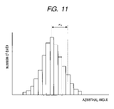
- FIG. 11 is a histogram showing a distribution of a plurality of reflection points on a moving object in the monitoring area, when they were measured;
- FIG. 12 is a diagram showing how a plurality of reflection points on a moving object are measured that was detected at a location extending over the detectable and undetectable areas;
- FIG. 13 is a diagram showing a surveillance radar of the present invention that is installed so that its angle-measuring direction is in vertical direction;
- FIG. 14 is a diagram showing an example of mounting a surveillance radar of the present invention at the front of an automobile
- FIG. 15 is a diagram showing an example of mounting a surveillance radar of the present invention at each side of an automobile.
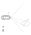
- FIG. 16 is a diagram showing an example of mounting a surveillance radar at the back of an automobile.
- FIGS. 1 through 16 Now some embodiments of the present invention are described below with reference to FIGS. 1 through 16 .
- the embodiments described below are intended to detect a moving object within a monitoring area with a monopulse surveillance radar capable of wide-angle monitoring, and measure the spatial width of the object occupying in the angle-measuring direction of the radar.
- FIGS. 1 and 12 A first embodiment of the present invention is described below with reference to FIGS. 1 and 12 .
- FIG. 1 is a block diagram illustrating the entire configuration of a surveillance radar of the first embodiment of the present invention.
- FIG. 2 is a diagram showing how a predetermined area is monitored with a surveillance radar of the first embodiment of the present invention that is installed on an outside wall of a building.
- a surveillance radar 1 of the present invention is applicable to an intrusion detection system for office buildings and residences.
- the surveillance radar apparatus 1 is installed, for example, on an outside wall of a building 2 , and detects a moving object like a human intruding into a radio emission area 3 .
- the surveillance radar apparatus 1 uses radio waves and has an advantage that an intruding object can be detected without fail even when visibility is low due to rain, fog, snow, or the like.
- a radar used in the surveillance radar apparatus 1 includes, for example, a 24 GHz band radar and a 76 GHz band radar.
- the surveillance radar apparatus 1 comprises an analogue circuit 5 , a signal processing circuit 13 , and an alarm device 14 , as shown in FIG. 1 .
- the analogue circuit 5 of the surveillance radar apparatus 1 is provided with a transmission system including a modulator 6 , an oscillator 7 , and a transmitting antenna 8 , and a receive system including a receiving antenna 9 , a mixer 10 , an amplifier 11 , and an A/D converter 12 .
- the signal processing circuit 13 is a circuit that processes a signal input from the A/D converter 12 in the analogue circuit and identifies a detected object, and contains an FFT processing unit 15 , a peak extract unit 16 , a detected object measuring unit 17 , a width calculation unit 18 , a detected object tracking unit 19 , a memory unit 22 , and a detected object identify unit 23 . Also, the detected object tracking unit 19 has a width correction unit 20 and a position correction unit 21 .
- the alarm device 14 is a device that receives an output from the signal processing circuit 13 when a detected object is identified as an intruder, and gives an alarm.
- FIG. 3 is a graph for explaining a modulation method for the two-frequency CW modulation technique.
- FIG. 4 is a frequency spectrum diagram showing that a Doppler frequency, caused by the reflection of a transmitted wave from a moving object, is observed as a peak;
- FIG. 5 is a diagram showing an exemplary antenna configuration when the monopulse angle measuring techniques is implemented using patch antennas
- FIG. 6 is a diagram showing the dependence on azimuthal angle of the sum and difference signals of signals received by two antennas implementing the monopulse angle measuring techniques
- FIG. 7 is a graph for explaining the azimuthal angle measuring principle of the monopulse angle measuring techniques
- FIG. 8 is a frequency spectrum diagram showing that a peak, caused by a Doppler frequency resulting from the reflection of a transmitted wave by a moving object, is observed with frequency width;
- FIG. 9 is a diagram illustrating that the velocity of a moving object relative to the radar varies depending on the location of the object moving within the monitoring area;
- FIG. 10 is a diagram showing how a plurality of reflection points on a moving object in the monitoring area are measured
- FIG. 11 is a histogram showing a distribution of a plurality of reflection points on a moving object in the monitoring area, when they were measured;
- FIG. 12 is a diagram showing how a plurality of reflection points on a moving object are measured that was detected at a location extending over the detectable and undetectable areas;
- the oscillator 7 in the analogue circuit 5 performs an oscillation at a frequency based on a modulation signal from the modulator 6 , and the high frequency signal is radiated from the transmitting antenna 8 to a monitoring area, as a transmit radiowave.
- the principle of detection of a moving object by the surveillance radar 1 namely, the principle of measurement of the distance to a detected object and moving velocity of the same is described, for the case where the two-frequency continuous wave (CW) modulation technique is adopted.
- CW continuous wave
- a modulation signal is input to the oscillator 7 and radio waves are transmitted with the frequency temporally switched between two frequencies f 1 and f 2 as shown in FIG. 3 .
- a radiowave transmitted from the transmitting antenna 8 is reflected by an object within the radiation area, and the reflected radio signal is received by the receiving antenna 9 .
- This received signal is mixed with the transmitted signal in the mixer circuit 10 to produce an intermediate frequency, which is output to the amplifier 11 .
- the signal amplified by and output from the amplifier 11 is converted to a digital signal by the A/D converter 12 , and sent to the signal processing circuit 13 .
- a frequency spectrum is determined by the FFT processing unit 15 in the signal processing circuit 13 that performs a fast Fourier transform.
- the signal reflected back from a moving object within a detection area has a frequency different from the transmit frequency due to the influence of Doppler effect, and therefore, when frequency spectrum is determined, a peak 24 is observed in the frequency corresponding to the moving velocity of an object, as shown in FIG. 4 .
- a frequency spectrum determined when no moving object is present within a detection area is prestored, this frequency spectrum being called a noise spectrum.
- a frequency spectrum is determined in sequence periodically under surveillance condition, and compared with a noise spectrum in the peak extract unit 16 to calculate the signal noise ratio (S/N).
- S/N is high means a peak is high, and hence the receive intensity of a radiowave reflected by a moving object is high.
- a relative velocity (v) to a radar at the reflection point is calculated by the following equation (equation 1), with respect to a peak with high S/N.
- the detected object measuring unit 17 measures the phase of each of transmit frequencies f 1 and f 2 for the above signal peak, and calculates the range from a phase difference ⁇ by equation 2, based on the principle of the two-frequency CW modulation technique.
- FIG. 5 shows an exemplary configuration of antennas.
- Each antenna is composed of patch antennas, and a receiving antenna is composed of two channels such as 9 a and 9 b .
- the azimuth dependent intensity of the sum signal (Sum) of the powers received by the two antennas and that of the difference signal (Diff) are as shown in FIG. 6 , and its ratio calculated is as shown in FIG. 7 .
- this azimuth dependency is pre-measured for each radar and stored in the memory unit 22 . If a peak with high S/N is detected, the azimuthal coordinate ( ⁇ ) of the reflection point is identified, by measuring the power ratio and phase difference between Sum and Diff and referencing the azimuth dependency data stored in the memory unit 22 .
- Described above is a procedure for measuring the azimuthal position from the place where a radar is installed.
- the relative velocity of the object to a radar differs with a reflection point on the object.
- the relative velocity of the reflection point 27 to the radar is V cos ⁇ 1 indicated by an arrow 28
- that of a reflection point 29 is V cos ⁇ 2 indicated by an arrow 30 .
- a frequency spectrum is determined, a peak will be observed on a different frequency.
- an S/N threshold level is set and stored in the memory unit 22 in advance for extracting a frequency at which the distance and azimuth is measured.
- the measured data are distributed within the area on the radar front side where detected objects 26 exist and surrounding area, like a data point 31 in FIG. 10 .
- the width calculation unit 18 calculates the azimuthal spatial width of a detected object from the distribution of data points determined in this way. This processing by the width calculation unit 18 is described below.
- R represents a gravity point of the measured distances of a plurality of reflection points, with respect to S/N.
- representative values of the velocity and azimuthal coordinate of detected objects should be determined by the following equations 6 and 7, in the detected object measuring unit 17 .
- V V i ⁇ SN i / ⁇ SN i (6)
- ⁇ ⁇ i ⁇ SN i / ⁇ SN i (7)
- the distance R, velocity V, and azimuthal coordinate ⁇ are input to the positional correction unit 21 provided in the detected object track unit 19 , and the width W in azimuthal direction is input to the width correction unit 20 .
- the positional correction unit 21 currently calculated actual information is corrected based on the current measurement information to be predicted from the past detected object measurement information stored in the memory unit 22 .
- a Kalman filter, an ⁇ - ⁇ - ⁇ filter, or the like is employed that has been used in the radar technology field.
- the width correction unit 20 performs the following processing.
- the azimuthal width to be input to the width correction unit is expressed as W m
- the azimuthal width to be corrected by and output from the width correction unit 20 is expressed as W′ m
- the subscript m is an indicator of time, and the value decreases as it becomes older.
- calculated values are corrected according to the following equation 8.
- W′ m W m + ⁇ ( W′ m-1 ⁇ W m ) (8)
- the width correction unit 20 also calculates the azimuthal coordinates at which both ends of a detected object are positioned.
- the distance to a detected object which is an output of the positional correction unit 21 , is expressed as R t , azimuthal position as ⁇ t , and a value obtained through the above width correction processing as W t
- the leftmost azimuthal coordinate ⁇ left is calculated by the following equation 9
- the rightmost azimuthal coordinate ⁇ right is calculated by the equation 10.
- ⁇ left ⁇ t ⁇ arctan( W t (2 R t )) (9)
- ⁇ right ⁇ t +arctan( W t /(2 R t )) (10)
- arctan is an inverse function of the tangent of a trigonometric function.
- the width correction unit 20 also outputs the information indicating that the W t measured as a spatial width in azimuthal direction is a lower limit value of the spatial width in azimuthal direction of the detected object.
- the moving velocity, distance, azimuthal position, and azimuthal width of the detected object determined in this way are input to the detected object identify unit 23 .
- the detected object identify unit 23 when the detected object is located within a monitoring area, if the azimuthal width of the object is within possible values for a human, for example between 40 cm and 100 cm, the object is judged to be a human and a measure, such as reporting to the security firm through the alarm device 14 , is taken.
- the surveillance radar apparatus of the present invention is applicable not only to the outdoor monitoring for intruders but also to monitoring the indoor human movements. For example, it is possible to install on an inside wall of a house and track the positions of dweller(s) of the house by distinguishing the dweller from other moving object(s), such as a cat or other pets.
- a surveillance radar apparatus of the present invention employs the monopulse angle measuring techniques requiring no angular displacement of radiated waves for measuring the spatial width in azimuthal direction of a detected object, and allow the kind of a detected object to be identified based on the information on the width thereof. This reduces the cost compared with a radar requiring angular displacement of radiated waves and also reduces false alarms to improve the reliability.
- a surveillance radar of this embodiment is capable of judging whether a detected moving object is human or not, using this radar for crime prevention purpose makes it possible to prevent any intrusion.
- FIG. 13 is a diagram showing an example of installing a surveillance radar apparatus so that its angle measuring direction is in vertical direction.
- Installing in this way makes it possible to measure the vertical width instead of the azimuthal width determined in the first embodiment. That is, the height of a detected object can be measured. Accordingly, if the vertical width of a detected object is within the possible values for a human, such as between 1 m and 2.5 m, the detected object identify unit 23 judges that a human walking upright is intruding, and actuates the alarm device 14 based on the judgment.
- a surveillance radar apparatus of the first embodiment and that of this embodiment simultaneously allows both the azimuthal width (lateral width) and the vertical width (height) to be measured simultaneously.
- a surveillance radar of this embodiment is used for crime prevention purpose, it is possible to increase the accuracy in judging whether a detected object is a human or not, which is effective for preventing intrusion.
- FIGS. 14 through 16 a third embodiment of the present invention is described with reference to FIGS. 14 through 16 .
- FIG. 14 is a diagram showing an example of using a surveillance radar apparatus of the present invention by mounting the same at the front of an automobile.
- FIG. 15 is a diagram showing an example of using a surveillance radar apparatus of the present invention by mounting the same at both sides of an automobile.
- FIG. 16 is a diagram showing an example of using a surveillance radar apparatus of the present invention by mounting the same at the back of an automobile.
- the position and width of an object 34 located in front of the automobile is measured by a surveillance radar apparatus 1 , and the measurement values are input to the detected object identify unit 23 .
- the detected object identify unit 23 judges that the detected object is an automobile if the azimuthal width of a detected object is within the possible values for an automobile, for example between 1.5 m and 3 m.
- an action is taken, such as, an alarm is given to the driver through the alarm device 14 .
- a surveillance radar apparatus of this embodiment can be mounted on a vehicle, in which case it is possible to accurately judge whether or not a detected object will block a traveling vehicle on which a radar apparatus is mounted, or whether or not the detected object will collide with the vehicle, and thus an accident can be prevented.
Abstract
Description
where c is light velocity, fd Doppler frequency, f oscillating frequency.
where Δf=f2−f1.
W=A×R×tan(σθ) (3)
A=W known/(R known×tan(σθ)) (4)
R=R i ×SN i /τSN i (5)
V=V i ×SN i /ΣSN i (6)
θ=θi ×SN i /ΣSN i (7)
W′ m =W m+α(W′ m-1 −W m) (8)
θleft=θt−arctan(W t(2R t)) (9)
θright=θt+arctan(W t/(2R t)) (10)
L<(W t +L car)/2 (11)
Claims (22)
Applications Claiming Priority (1)
| Application Number | Priority Date | Filing Date | Title |
|---|---|---|---|
| JP2005344956A JP2007147532A (en) | 2005-11-30 | 2005-11-30 | Radar system |
Publications (1)
| Publication Number | Publication Date |
|---|---|
| US7463182B1 true US7463182B1 (en) | 2008-12-09 |
Family
ID=38209096
Family Applications (1)
| Application Number | Title | Priority Date | Filing Date |
|---|---|---|---|
| US11/483,100 Expired - Fee Related US7463182B1 (en) | 2005-11-30 | 2006-07-10 | Radar apparatus |
Country Status (2)
| Country | Link |
|---|---|
| US (1) | US7463182B1 (en) |
| JP (1) | JP2007147532A (en) |
Cited By (17)
| Publication number | Priority date | Publication date | Assignee | Title |
|---|---|---|---|---|
| US20060089799A1 (en) * | 2004-10-21 | 2006-04-27 | Kenjiro Endoh | Vehicle detector and vehicle detecting method |
| US20090072957A1 (en) * | 2007-09-14 | 2009-03-19 | Honeywell International Inc. | Radio frequency proximity sensor and sensor system |
| EP2065727A1 (en) * | 2007-11-16 | 2009-06-03 | Robert Bosch GmbH | Method for estimating the width of radar objects |
| US20120313809A1 (en) * | 2011-06-10 | 2012-12-13 | Sony Corporation | Signal processing unit and method |
| EP2577640A1 (en) * | 2010-06-01 | 2013-04-10 | Autoliv ASP, Inc. | Vehicle radar system and method for detecting objects |
| US8810650B1 (en) * | 2009-04-20 | 2014-08-19 | The United States Of America, As Represented By The Secretary Of The Navy | Agile interrogation hyperspectral imager and method of using same |
| US20160116915A1 (en) * | 2014-10-22 | 2016-04-28 | Honeywell International Inc. | Surveying areas using a radar system and an unmanned aerial vehicle |
| US20180211502A1 (en) * | 2017-01-25 | 2018-07-26 | Honeywell International Inc. | Apparatus and approach for accurate monitoring of space |
| WO2019022999A1 (en) * | 2017-07-28 | 2019-01-31 | Valeo Radar Systems, Inc. | Broadside detection system and techniques for use in a vehicular radar |
| US20190064840A1 (en) * | 2017-08-31 | 2019-02-28 | Uber Technologies, Inc. | Systems and Methods for Controlling an Autonomous Vehicle with Occluded Sensor Zones |
| US10438464B1 (en) | 2018-06-06 | 2019-10-08 | Ademco Inc. | Systems and methods for determining and verifying a presence of an object or an intruder in a secured area |
| WO2020161703A3 (en) * | 2019-02-06 | 2020-09-17 | Essence Security International (E.S.I.) Ltd. | Radar location system and method |
| US20210055378A1 (en) * | 2018-02-12 | 2021-02-25 | Niko Nv | Electric or electronic device module comprising at least one radar sensor |
| US10996325B2 (en) | 2018-11-30 | 2021-05-04 | Ademco Inc. | Systems and methods for adjusting a signal broadcast pattern of an intrusion detector |
| US11074794B2 (en) | 2018-11-30 | 2021-07-27 | Ademco Inc. | Systems and methods for activating and deactivating controlled devices in a secured area |
| US11282374B2 (en) | 2019-08-19 | 2022-03-22 | Ademco Inc. | Systems and methods for building and using a false alarm predicting model to determine whether to alert a user and/or relevant authorities about an alarm signal from a security system |
| IL264696B2 (en) * | 2019-02-06 | 2023-06-01 | Essence Security International Esi Ltd | Radar location system and method |
Families Citing this family (13)
| Publication number | Priority date | Publication date | Assignee | Title |
|---|---|---|---|---|
| JP2007147532A (en) * | 2005-11-30 | 2007-06-14 | Hitachi Ltd | Radar system |
| JP4643475B2 (en) * | 2006-03-10 | 2011-03-02 | 株式会社東芝 | Radar equipment |
| JP4892518B2 (en) * | 2008-05-20 | 2012-03-07 | 日立オートモティブシステムズ株式会社 | Vehicle external recognition device and vehicle system |
| JP5042201B2 (en) * | 2008-12-02 | 2012-10-03 | 本田技研工業株式会社 | Vehicle alarm device |
| WO2010100852A1 (en) * | 2009-03-06 | 2010-09-10 | 日本電気株式会社 | Discrimination sensor, electronic device, monitoring system, and method for discriminating subject to be tested |
| KR101311393B1 (en) | 2012-01-09 | 2013-09-25 | 포항공과대학교 산학협력단 | Method for recognizing target using radar signal and apparatus thereof |
| JP5978754B2 (en) * | 2012-05-16 | 2016-08-24 | 株式会社デンソー | Radar equipment |
| JP2013238520A (en) * | 2012-05-16 | 2013-11-28 | Denso Corp | Radar device |
| JP5605395B2 (en) * | 2012-06-08 | 2014-10-15 | 株式会社デンソー | Vehicle determination device and program |
| JP2014002012A (en) * | 2012-06-18 | 2014-01-09 | Denso Corp | Radar device and program |
| WO2016178270A1 (en) * | 2015-05-01 | 2016-11-10 | 三菱電機株式会社 | Radar device |
| JP2019066290A (en) * | 2017-09-29 | 2019-04-25 | ミツミ電機株式会社 | Radar device and method for detecting target |
| KR101877219B1 (en) * | 2018-01-26 | 2018-07-12 | 엘아이지넥스원 주식회사 | Apparatus and method for recognizing a target based on 2D data |
Citations (12)
| Publication number | Priority date | Publication date | Assignee | Title |
|---|---|---|---|---|
| JPH11183612A (en) | 1997-12-19 | 1999-07-09 | Fujitsu Ten Ltd | Signal processing method for radar apparatus |
| JP2000338231A (en) | 1999-05-31 | 2000-12-08 | Mitsubishi Electric Corp | Intruder detecting device |
| US6404506B1 (en) * | 1998-03-09 | 2002-06-11 | The Regents Of The University Of California | Non-intrusive laser-based system for detecting objects moving across a planar surface |
| JP2002236171A (en) | 2000-12-06 | 2002-08-23 | Omron Corp | Invader detection method and invader detection device |
| US6680689B1 (en) * | 2003-03-28 | 2004-01-20 | Visteon Global Technologies, Inc. | Method for determining object classification from side-looking sensor data |
| JP2004239744A (en) | 2003-02-06 | 2004-08-26 | Hitachi Ltd | Radar equipment |
| JP2007147532A (en) * | 2005-11-30 | 2007-06-14 | Hitachi Ltd | Radar system |
| US7385550B2 (en) * | 2002-09-20 | 2008-06-10 | Robert Bosch Gmbh | Method for measuring distances and speeds of several objects by means of an FMCW radar |
| US7391361B2 (en) * | 2003-12-26 | 2008-06-24 | Fujitsu Ten Limited | Signal processing method for FM-CW radar |
| US7394355B2 (en) * | 2004-02-02 | 2008-07-01 | Sjoenell Goeran | Vehicle collision detector |
| US20080186223A1 (en) * | 2004-09-29 | 2008-08-07 | Robert Bosch Gmbh | Radar Sensor for Motor Vehicles |
| US7417584B1 (en) * | 1989-11-08 | 2008-08-26 | Lockheed Martin Corporation | Monopulse radar estimation of target altitude at low angles of elevation |
Family Cites Families (9)
| Publication number | Priority date | Publication date | Assignee | Title |
|---|---|---|---|---|
| JP3843502B2 (en) * | 1996-09-30 | 2006-11-08 | マツダ株式会社 | Vehicle motion recognition device |
| JP3385304B2 (en) * | 1997-08-29 | 2003-03-10 | 三菱電機株式会社 | Automotive radar equipment |
| JP4082473B2 (en) * | 1997-12-19 | 2008-04-30 | 富士通テン株式会社 | Radar apparatus signal processing method and apparatus |
| JP3450189B2 (en) * | 1998-06-16 | 2003-09-22 | ダイハツ工業株式会社 | Pedestrian detection system and control method thereof |
| JP2000206241A (en) * | 1999-01-13 | 2000-07-28 | Honda Motor Co Ltd | Radar apparatus |
| JP4267171B2 (en) * | 1999-05-10 | 2009-05-27 | 本田技研工業株式会社 | Pedestrian detection device |
| JP2001209787A (en) * | 1999-11-15 | 2001-08-03 | Omron Corp | Device and method for processing information, recording medium and device for detecting object |
| JP4698941B2 (en) * | 2003-11-07 | 2011-06-08 | 三菱電機株式会社 | Target classification device |
| JP4754292B2 (en) * | 2005-07-25 | 2011-08-24 | セコム株式会社 | Radar equipment |
-
2005
- 2005-11-30 JP JP2005344956A patent/JP2007147532A/en active Pending
-
2006
- 2006-07-10 US US11/483,100 patent/US7463182B1/en not_active Expired - Fee Related
Patent Citations (12)
| Publication number | Priority date | Publication date | Assignee | Title |
|---|---|---|---|---|
| US7417584B1 (en) * | 1989-11-08 | 2008-08-26 | Lockheed Martin Corporation | Monopulse radar estimation of target altitude at low angles of elevation |
| JPH11183612A (en) | 1997-12-19 | 1999-07-09 | Fujitsu Ten Ltd | Signal processing method for radar apparatus |
| US6404506B1 (en) * | 1998-03-09 | 2002-06-11 | The Regents Of The University Of California | Non-intrusive laser-based system for detecting objects moving across a planar surface |
| JP2000338231A (en) | 1999-05-31 | 2000-12-08 | Mitsubishi Electric Corp | Intruder detecting device |
| JP2002236171A (en) | 2000-12-06 | 2002-08-23 | Omron Corp | Invader detection method and invader detection device |
| US7385550B2 (en) * | 2002-09-20 | 2008-06-10 | Robert Bosch Gmbh | Method for measuring distances and speeds of several objects by means of an FMCW radar |
| JP2004239744A (en) | 2003-02-06 | 2004-08-26 | Hitachi Ltd | Radar equipment |
| US6680689B1 (en) * | 2003-03-28 | 2004-01-20 | Visteon Global Technologies, Inc. | Method for determining object classification from side-looking sensor data |
| US7391361B2 (en) * | 2003-12-26 | 2008-06-24 | Fujitsu Ten Limited | Signal processing method for FM-CW radar |
| US7394355B2 (en) * | 2004-02-02 | 2008-07-01 | Sjoenell Goeran | Vehicle collision detector |
| US20080186223A1 (en) * | 2004-09-29 | 2008-08-07 | Robert Bosch Gmbh | Radar Sensor for Motor Vehicles |
| JP2007147532A (en) * | 2005-11-30 | 2007-06-14 | Hitachi Ltd | Radar system |
Cited By (28)
| Publication number | Priority date | Publication date | Assignee | Title |
|---|---|---|---|---|
| US20060089799A1 (en) * | 2004-10-21 | 2006-04-27 | Kenjiro Endoh | Vehicle detector and vehicle detecting method |
| US7509217B2 (en) * | 2004-10-21 | 2009-03-24 | Alpine Electronics, Inc. | Vehicle detector and vehicle detecting method |
| US20090072957A1 (en) * | 2007-09-14 | 2009-03-19 | Honeywell International Inc. | Radio frequency proximity sensor and sensor system |
| EP2065727A1 (en) * | 2007-11-16 | 2009-06-03 | Robert Bosch GmbH | Method for estimating the width of radar objects |
| US8810650B1 (en) * | 2009-04-20 | 2014-08-19 | The United States Of America, As Represented By The Secretary Of The Navy | Agile interrogation hyperspectral imager and method of using same |
| EP2577640A1 (en) * | 2010-06-01 | 2013-04-10 | Autoliv ASP, Inc. | Vehicle radar system and method for detecting objects |
| EP2577640A4 (en) * | 2010-06-01 | 2013-11-06 | Autoliv Asp Inc | Vehicle radar system and method for detecting objects |
| US20120313809A1 (en) * | 2011-06-10 | 2012-12-13 | Sony Corporation | Signal processing unit and method |
| US20160116915A1 (en) * | 2014-10-22 | 2016-04-28 | Honeywell International Inc. | Surveying areas using a radar system and an unmanned aerial vehicle |
| US9429945B2 (en) * | 2014-10-22 | 2016-08-30 | Honeywell International Inc. | Surveying areas using a radar system and an unmanned aerial vehicle |
| US20180211502A1 (en) * | 2017-01-25 | 2018-07-26 | Honeywell International Inc. | Apparatus and approach for accurate monitoring of space |
| CN108344993A (en) * | 2017-01-25 | 2018-07-31 | 霍尼韦尔国际公司 | The device and method accurately monitored for space |
| WO2019022999A1 (en) * | 2017-07-28 | 2019-01-31 | Valeo Radar Systems, Inc. | Broadside detection system and techniques for use in a vehicular radar |
| US10585188B2 (en) | 2017-07-28 | 2020-03-10 | Valeo Radar Systems, Inc. | Broadside detection system and techniques for use in a vehicular radar |
| US20190064840A1 (en) * | 2017-08-31 | 2019-02-28 | Uber Technologies, Inc. | Systems and Methods for Controlling an Autonomous Vehicle with Occluded Sensor Zones |
| US11625045B2 (en) * | 2017-08-31 | 2023-04-11 | Uatc, Llc | Systems and methods for controlling an autonomous vehicle with occluded sensor zones |
| US20210055378A1 (en) * | 2018-02-12 | 2021-02-25 | Niko Nv | Electric or electronic device module comprising at least one radar sensor |
| US11782124B2 (en) * | 2018-02-12 | 2023-10-10 | Niko Nv | Electric or electronic device module comprising at least one radar sensor |
| US10438464B1 (en) | 2018-06-06 | 2019-10-08 | Ademco Inc. | Systems and methods for determining and verifying a presence of an object or an intruder in a secured area |
| EP3579207A1 (en) * | 2018-06-06 | 2019-12-11 | Ademco Inc. | Systems and methods for determining and verifying a presence of an object or an intruder in a secured area |
| US10996325B2 (en) | 2018-11-30 | 2021-05-04 | Ademco Inc. | Systems and methods for adjusting a signal broadcast pattern of an intrusion detector |
| US11074794B2 (en) | 2018-11-30 | 2021-07-27 | Ademco Inc. | Systems and methods for activating and deactivating controlled devices in a secured area |
| US20220283279A1 (en) * | 2019-02-06 | 2022-09-08 | Essence Security International (E.S.I.) Ltd. | Radar location system and method |
| WO2020161703A3 (en) * | 2019-02-06 | 2020-09-17 | Essence Security International (E.S.I.) Ltd. | Radar location system and method |
| IL264696B2 (en) * | 2019-02-06 | 2023-06-01 | Essence Security International Esi Ltd | Radar location system and method |
| US11754697B2 (en) * | 2019-02-06 | 2023-09-12 | Essence Security International (E.S.I.) Ltd. | Radar location system and method |
| US11282374B2 (en) | 2019-08-19 | 2022-03-22 | Ademco Inc. | Systems and methods for building and using a false alarm predicting model to determine whether to alert a user and/or relevant authorities about an alarm signal from a security system |
| US11776387B2 (en) | 2019-08-19 | 2023-10-03 | Ademco Inc. | Systems and methods for building and using a false alarm predicting model to determine whether to alert a user and/or relevant authorities about an alarm signal from a security system |
Also Published As
| Publication number | Publication date |
|---|---|
| JP2007147532A (en) | 2007-06-14 |
Similar Documents
| Publication | Publication Date | Title |
|---|---|---|
| US7463182B1 (en) | Radar apparatus | |
| US20060267764A1 (en) | Object detection sensor | |
| US6218979B1 (en) | Wide area time domain radar array | |
| US6400307B2 (en) | System and method for intrusion detection using a time domain radar array | |
| US7084761B2 (en) | Security system | |
| US10162046B2 (en) | System and method for detecting blockage in an automotive radar | |
| US7592944B2 (en) | System and method for intrusion detection using a time domain radar array | |
| EP1441318B1 (en) | Security system | |
| US8593333B2 (en) | Radar sensor with frontal and lateral emission | |
| US20100238066A1 (en) | Method and system for generating a target alert | |
| JPH0798377A (en) | Collision-prevention alarm system and method for land vehicle | |
| Tahmoush et al. | Radar surveillance in urban environments | |
| JP3909370B2 (en) | Security sensor | |
| JP2017134012A (en) | Vehicle detection device, vehicle detection device control method and vehicle detection program | |
| EP3865909A1 (en) | Electronic device, method for controlling electronic device, and program for controlling electronic device | |
| JP2023073521A (en) | Electronic apparatus, method for controlling electronic apparatus, and program | |
| JP4479268B2 (en) | Aircraft detection device | |
| JP2000099875A (en) | Vehicle detector | |
| JP2007064655A (en) | Moving body measuring system | |
| Bouhlel et al. | FMCW radar system for transponder identification | |
| Yan | Parameter measurements of moving targets using a 24‐GHz radar | |
| Won et al. | 24ghz fmcw radar module for pedestrian detection in crosswalks | |
| JP2000111644A (en) | Vehicle detecting device | |
| CN114047501A (en) | Indoor positioning system based on millimeter wave radar |
Legal Events
| Date | Code | Title | Description |
|---|---|---|---|
| AS | Assignment |
Owner name: HITACHI, LTD., JAPAN Free format text: ASSIGNMENT OF ASSIGNORS INTEREST;ASSIGNORS:MORINAGA, MITSUTOSHI;NAGASAKU, TOSHIYUKI;REEL/FRAME:018093/0479 Effective date: 20060626 |
|
| FEPP | Fee payment procedure |
Free format text: PAYER NUMBER DE-ASSIGNED (ORIGINAL EVENT CODE: RMPN); ENTITY STATUS OF PATENT OWNER: LARGE ENTITY |
|
| FEPP | Fee payment procedure |
Free format text: PAYOR NUMBER ASSIGNED (ORIGINAL EVENT CODE: ASPN); ENTITY STATUS OF PATENT OWNER: LARGE ENTITY |
|
| REMI | Maintenance fee reminder mailed | ||
| LAPS | Lapse for failure to pay maintenance fees | ||
| STCH | Information on status: patent discontinuation |
Free format text: PATENT EXPIRED DUE TO NONPAYMENT OF MAINTENANCE FEES UNDER 37 CFR 1.362 |
|
| FP | Lapsed due to failure to pay maintenance fee |
Effective date: 20121209 |