US7471437B2 - Electrochromic materials and devices - Google Patents
Electrochromic materials and devices Download PDFInfo
- Publication number
- US7471437B2 US7471437B2 US10/813,885 US81388504A US7471437B2 US 7471437 B2 US7471437 B2 US 7471437B2 US 81388504 A US81388504 A US 81388504A US 7471437 B2 US7471437 B2 US 7471437B2
- Authority
- US
- United States
- Prior art keywords
- electrochromic
- electrochromic device
- electrode
- substituted
- group
- Prior art date
- Legal status (The legal status is an assumption and is not a legal conclusion. Google has not performed a legal analysis and makes no representation as to the accuracy of the status listed.)
- Expired - Fee Related, expires
Links
- 0 *C(S(C(c1ccccc1)=C1)(=O)=O)=CC1=C(C#N)C#N Chemical compound *C(S(C(c1ccccc1)=C1)(=O)=O)=CC1=C(C#N)C#N 0.000 description 2
- PIKCOZNAMJIKGV-UHFFFAOYSA-N CC1(C)OC(=O)C(=C2C=C(C3=CC=CC=C3)S(=O)(=O)C(C3=CC=CC=C3)=C2)C(=O)O1 Chemical compound CC1(C)OC(=O)C(=C2C=C(C3=CC=CC=C3)S(=O)(=O)C(C3=CC=CC=C3)=C2)C(=O)O1 PIKCOZNAMJIKGV-UHFFFAOYSA-N 0.000 description 2
- WSWGDRKKNVAGQV-UHFFFAOYSA-N N#CN=C1C=C(C2=CC=C(C(F)(F)F)C=C2)S(=O)(=O)C(C2=CC=C(C(F)(F)F)C=C2)=C1 Chemical compound N#CN=C1C=C(C2=CC=C(C(F)(F)F)C=C2)S(=O)(=O)C(C2=CC=C(C(F)(F)F)C=C2)=C1 WSWGDRKKNVAGQV-UHFFFAOYSA-N 0.000 description 2
- RGOSFLGTRCSMCE-COEJQBHMSA-N O=C(O)C1=CC=C(/N=C2/C=C(C3=CC=C([N+](=O)[O-])C=C3)S(=O)(=O)C(C3=CC=C([N+](=O)[O-])C=C3)=C2C(=O)O)C=C1C(F)(F)F Chemical compound O=C(O)C1=CC=C(/N=C2/C=C(C3=CC=C([N+](=O)[O-])C=C3)S(=O)(=O)C(C3=CC=C([N+](=O)[O-])C=C3)=C2C(=O)O)C=C1C(F)(F)F RGOSFLGTRCSMCE-COEJQBHMSA-N 0.000 description 2
- NAVDBUGAAOQFKA-UHFFFAOYSA-N O=C1C2=C(C=CC=C2)C(=O)C1=C1C=C(C2=CC=CC(C(F)(F)F)=C2)S(=O)(=O)C(C2=CC(C(F)(F)F)=CC=C2)=C1 Chemical compound O=C1C2=C(C=CC=C2)C(=O)C1=C1C=C(C2=CC=CC(C(F)(F)F)=C2)S(=O)(=O)C(C2=CC(C(F)(F)F)=CC=C2)=C1 NAVDBUGAAOQFKA-UHFFFAOYSA-N 0.000 description 2
- VMOJKASGYHVUEP-UHFFFAOYSA-N O=C1C=C(C2=CC=CC(C(F)(F)F)=C2)S(=O)(=O)C(C2=CC(C(F)(F)F)=CC=C2)=C1 Chemical compound O=C1C=C(C2=CC=CC(C(F)(F)F)=C2)S(=O)(=O)C(C2=CC(C(F)(F)F)=CC=C2)=C1 VMOJKASGYHVUEP-UHFFFAOYSA-N 0.000 description 2
- NEVCBPUJOKBDLC-MSUUIHNZSA-N CC1=C(C2=CC(C(F)(F)F)=CC=C2)S(=O)(=O)C(C2=CC=CC(C(F)(F)F)=C2)=C(C(=O)O)/C1=C(/C#N)C(=O)O Chemical compound CC1=C(C2=CC(C(F)(F)F)=CC=C2)S(=O)(=O)C(C2=CC=CC(C(F)(F)F)=C2)=C(C(=O)O)/C1=C(/C#N)C(=O)O NEVCBPUJOKBDLC-MSUUIHNZSA-N 0.000 description 1
- PWGLDEPYBANPJY-GHVJWSGMSA-N CC1=C(C2=CC=CC=C2)S(=O)(=O)C(C2=CC=C(C(=O)O)C=C2)=C(Cl)/C1=C(\C#N)C1=CC=CC=C1 Chemical compound CC1=C(C2=CC=CC=C2)S(=O)(=O)C(C2=CC=C(C(=O)O)C=C2)=C(Cl)/C1=C(\C#N)C1=CC=CC=C1 PWGLDEPYBANPJY-GHVJWSGMSA-N 0.000 description 1
- MWXUCYOMSZOJSO-UHFFFAOYSA-N CC1=C(C2=CC=CC=C2)S(=O)(=O)C(C2=CC=CC=C2)=C(C)C1=C(C#N)C1=CC=C(C(=O)O)C=C1 Chemical compound CC1=C(C2=CC=CC=C2)S(=O)(=O)C(C2=CC=CC=C2)=C(C)C1=C(C#N)C1=CC=C(C(=O)O)C=C1 MWXUCYOMSZOJSO-UHFFFAOYSA-N 0.000 description 1
- OQTRAYPHLDUVAM-SDXDJHTJSA-N CC1=CC2=C(C=C1)C(=N/C#N)/C1=C(/C=C(C(=O)O)/C=C/1)S2(=O)=O Chemical compound CC1=CC2=C(C=C1)C(=N/C#N)/C1=C(/C=C(C(=O)O)/C=C/1)S2(=O)=O OQTRAYPHLDUVAM-SDXDJHTJSA-N 0.000 description 1
- BZQYIBDBNUNFEK-QREUMGABSA-N CC1=CC=C(/C(C#N)=C2\C(C)=C(C3=CC=CC(P(=O)(O)O)=C3)S(=O)(=O)C(C3=CC(P(=O)(O)O)=CC=C3)=C2S(C)(=O)=O)C=C1.O=S=O Chemical compound CC1=CC=C(/C(C#N)=C2\C(C)=C(C3=CC=CC(P(=O)(O)O)=C3)S(=O)(=O)C(C3=CC(P(=O)(O)O)=CC=C3)=C2S(C)(=O)=O)C=C1.O=S=O BZQYIBDBNUNFEK-QREUMGABSA-N 0.000 description 1
- KNIRESSRIHJKFL-UHFFFAOYSA-N CC1=CC=C(C2=C(C)C(=C(C)S(=O)(=O)C(F)(F)F)C(C)=C(C3=CC=C(C)C=C3)S2(=O)=O)C=C1 Chemical compound CC1=CC=C(C2=C(C)C(=C(C)S(=O)(=O)C(F)(F)F)C(C)=C(C3=CC=C(C)C=C3)S2(=O)=O)C=C1 KNIRESSRIHJKFL-UHFFFAOYSA-N 0.000 description 1
- LENJROPJIVBHTD-UHFFFAOYSA-N CC1=CC=C(C2=CC(=C(C)C#N)C=C(C3=CC=C(C)C=C3)S2(=O)=O)C=C1.O=S=O Chemical compound CC1=CC=C(C2=CC(=C(C)C#N)C=C(C3=CC=C(C)C=C3)S2(=O)=O)C=C1.O=S=O LENJROPJIVBHTD-UHFFFAOYSA-N 0.000 description 1
- MRUQWIWCNWFUSU-UHFFFAOYSA-N CC1=CC=C(C2=CC(=C(C)S(=O)(=O)C(F)(F)F)C=C(C3=CC=C(C)C=C3)S2(=O)=O)C=C1 Chemical compound CC1=CC=C(C2=CC(=C(C)S(=O)(=O)C(F)(F)F)C=C(C3=CC=C(C)C=C3)S2(=O)=O)C=C1 MRUQWIWCNWFUSU-UHFFFAOYSA-N 0.000 description 1
- IJKONSPOVSQTPW-UHFFFAOYSA-N CC1=CC=C(C2=CC(=C3C(=O)C4=C(C=CC=C4)C3=O)C=C(C3=CC=C(C(=O)O)C=C3)S2(=O)=O)C=C1 Chemical compound CC1=CC=C(C2=CC(=C3C(=O)C4=C(C=CC=C4)C3=O)C=C(C3=CC=C(C(=O)O)C=C3)S2(=O)=O)C=C1 IJKONSPOVSQTPW-UHFFFAOYSA-N 0.000 description 1
- MTWLQFKDFLAOFW-UHFFFAOYSA-N CC1=CC=C(C2=CC(=C3C(=O)C=CC3=O)C=C(C3=CC=CC=C3)S2(=O)=O)C=C1 Chemical compound CC1=CC=C(C2=CC(=C3C(=O)C=CC3=O)C=C(C3=CC=CC=C3)S2(=O)=O)C=C1 MTWLQFKDFLAOFW-UHFFFAOYSA-N 0.000 description 1
- RHXMAXGOECNVJG-UHFFFAOYSA-N CC1=CC=C(C2=CC(=C3C(=O)OC(C)(C)OC3=O)C=C(C(C)(C)C)S2(=O)=O)C=C1 Chemical compound CC1=CC=C(C2=CC(=C3C(=O)OC(C)(C)OC3=O)C=C(C(C)(C)C)S2(=O)=O)C=C1 RHXMAXGOECNVJG-UHFFFAOYSA-N 0.000 description 1
- VXIQYXFPWYLMAX-UHFFFAOYSA-N CC1=CC=C(C2=CC(=C3C(=O)OC(C)(C)OC3=O)C=C(C3=CC=C(C)C=C3)S2(=O)=O)C=C1 Chemical compound CC1=CC=C(C2=CC(=C3C(=O)OC(C)(C)OC3=O)C=C(C3=CC=C(C)C=C3)S2(=O)=O)C=C1 VXIQYXFPWYLMAX-UHFFFAOYSA-N 0.000 description 1
- KWZAMHCSXMKFNN-UHFFFAOYSA-N CC1=CC=C(C2=CC(=C3C4=C(C=C(C)C=C4)S(=O)(=O)C4=C3C=CC(C)=C4)C=C(C3=CC=C(C)C=C3)S2(=O)=O)C=C1 Chemical compound CC1=CC=C(C2=CC(=C3C4=C(C=C(C)C=C4)S(=O)(=O)C4=C3C=CC(C)=C4)C=C(C3=CC=C(C)C=C3)S2(=O)=O)C=C1 KWZAMHCSXMKFNN-UHFFFAOYSA-N 0.000 description 1
- WNKSPTUCXGZMJE-UHFFFAOYSA-N CC1=CC=C(C2=CC(=C3SC4=C(C=CC=C4)N3C)C=C(C3=CC=C(C)C=C3)S2(=O)=O)C=C1 Chemical compound CC1=CC=C(C2=CC(=C3SC4=C(C=CC=C4)N3C)C=C(C3=CC=C(C)C=C3)S2(=O)=O)C=C1 WNKSPTUCXGZMJE-UHFFFAOYSA-N 0.000 description 1
- GKTPVAQMPDIHKC-UHFFFAOYSA-N CC1=CC=C(C2=CC(=NN)C=C(C3=CC=C(C)C=C3)S2(=O)=O)C=C1 Chemical compound CC1=CC=C(C2=CC(=NN)C=C(C3=CC=C(C)C=C3)S2(=O)=O)C=C1 GKTPVAQMPDIHKC-UHFFFAOYSA-N 0.000 description 1
- UHLSVNWLPJGGEI-CVHNRXSESA-N CC1=CC=CC(F)=C1N/N=C1\C=C(C2=CC=C(C(=O)O)C=C2)S(=O)(=O)C(C2=CC=CC(C(F)(F)F)=C2)=C1.CFF Chemical compound CC1=CC=CC(F)=C1N/N=C1\C=C(C2=CC=C(C(=O)O)C=C2)S(=O)(=O)C(C2=CC=CC(C(F)(F)F)=C2)=C1.CFF UHLSVNWLPJGGEI-CVHNRXSESA-N 0.000 description 1
- PRFUNDIBRUAIJD-LHLOQNFPSA-N CCOC(=O)C1=CC=C(C2=C(C)/C(=N\C#N)C(C)=C(C3=CC=C(Cl)C=C3)S2(=O)=O)C=C1 Chemical compound CCOC(=O)C1=CC=C(C2=C(C)/C(=N\C#N)C(C)=C(C3=CC=C(Cl)C=C3)S2(=O)=O)C=C1 PRFUNDIBRUAIJD-LHLOQNFPSA-N 0.000 description 1
- NZNKRJJDAULMDN-LVWGJNHUSA-N COC(=O)/C(C1=CC=CC=C1)=C1/C=C(C2=CC=CC=C2)S(=O)(=O)C(C2=CC=C(C(=O)O)C=C2)=C1 Chemical compound COC(=O)/C(C1=CC=CC=C1)=C1/C=C(C2=CC=CC=C2)S(=O)(=O)C(C2=CC=C(C(=O)O)C=C2)=C1 NZNKRJJDAULMDN-LVWGJNHUSA-N 0.000 description 1
- ZLHKBAUKEXQJLL-UHFFFAOYSA-N COC(=O)C(C(=O)OC)=C1C=C(C2=CC=C(C(F)(F)F)C=C2)S(=O)(=O)C(C2=CC=C(C(F)(F)F)C=C2)=C1 Chemical compound COC(=O)C(C(=O)OC)=C1C=C(C2=CC=C(C(F)(F)F)C=C2)S(=O)(=O)C(C2=CC=C(C(F)(F)F)C=C2)=C1 ZLHKBAUKEXQJLL-UHFFFAOYSA-N 0.000 description 1
- VCPDADQMEQDACJ-UHFFFAOYSA-N COC(=O)C(C(=O)OC)=C1C=C(C2=CC=CC=C2)S(=O)(=O)C(C2=CC=C(C(=O)O)C=C2)=C1 Chemical compound COC(=O)C(C(=O)OC)=C1C=C(C2=CC=CC=C2)S(=O)(=O)C(C2=CC=C(C(=O)O)C=C2)=C1 VCPDADQMEQDACJ-UHFFFAOYSA-N 0.000 description 1
- ODPBNJQPVQWMPF-UHFFFAOYSA-N COC(=O)C1=C(C(=O)OC)SC(=C2C=C(C3=CC=C(C)C=C3)S(=O)(=O)C(C3=CC=C(C)C=C3)=C2)S1 Chemical compound COC(=O)C1=C(C(=O)OC)SC(=C2C=C(C3=CC=C(C)C=C3)S(=O)(=O)C(C3=CC=C(C)C=C3)=C2)S1 ODPBNJQPVQWMPF-UHFFFAOYSA-N 0.000 description 1
- CYUPPMXPOWRRJD-UHFFFAOYSA-N Cc(cc1)ccc1C(S(C(c1ccc(C)cc1)=C1)(=O)=O)=CC1=C(C#N)S(C)(=O)=O Chemical compound Cc(cc1)ccc1C(S(C(c1ccc(C)cc1)=C1)(=O)=O)=CC1=C(C#N)S(C)(=O)=O CYUPPMXPOWRRJD-UHFFFAOYSA-N 0.000 description 1
- CEWSWRGCFBDHHC-OCEACIFDSA-N N#C/C(C1=CC=CC=C1)=C1/C=C(C2=CC=CC=C2)S(=O)(=O)C(C2=CC=C(CCCP(=O)(O)O)C=C2)=C1 Chemical compound N#C/C(C1=CC=CC=C1)=C1/C=C(C2=CC=CC=C2)S(=O)(=O)C(C2=CC=C(CCCP(=O)(O)O)C=C2)=C1 CEWSWRGCFBDHHC-OCEACIFDSA-N 0.000 description 1
- VDIGXQDFRNHGMC-QZQOTICOSA-N N#C/C(C1=NC2=C(C=CC=C2)S1)=C1/C=C(C2=CC=CC=C2)S(=O)(=O)C(C2=CC=C(C(=O)O)C=C2)=C1 Chemical compound N#C/C(C1=NC2=C(C=CC=C2)S1)=C1/C=C(C2=CC=CC=C2)S(=O)(=O)C(C2=CC=C(C(=O)O)C=C2)=C1 VDIGXQDFRNHGMC-QZQOTICOSA-N 0.000 description 1
- FWDFSLCJMOOYJU-CJLVFECKSA-N N#C/N=C1/C=C(C2=CC=C(OC=O)C=C2)S(=O)(=O)C(C2=CC=C(C(=O)O)C=C2)=C1 Chemical compound N#C/N=C1/C=C(C2=CC=C(OC=O)C=C2)S(=O)(=O)C(C2=CC=C(C(=O)O)C=C2)=C1 FWDFSLCJMOOYJU-CJLVFECKSA-N 0.000 description 1
- KYGUQWHKONHOSK-UHFFFAOYSA-N O=C(O)C(C(=O)O)=C1C=C(C2=CC=CC(C(F)(F)F)=C2)S(=O)(=O)C(C2=CC(C(F)(F)F)=CC=C2)=C1 Chemical compound O=C(O)C(C(=O)O)=C1C=C(C2=CC=CC(C(F)(F)F)=C2)S(=O)(=O)C(C2=CC(C(F)(F)F)=CC=C2)=C1 KYGUQWHKONHOSK-UHFFFAOYSA-N 0.000 description 1
- PBHBTDGJEAWDAD-RDRPBHBLSA-N O=C(O)C1=CC=C(C2=C/C(=N\NC3=CC=C([N+](=O)[O-])C=C3[N+](=O)[O-])C=C(C3=CC=CC(C(F)(F)F)=C3)S2(=O)=O)C=C1 Chemical compound O=C(O)C1=CC=C(C2=C/C(=N\NC3=CC=C([N+](=O)[O-])C=C3[N+](=O)[O-])C=C(C3=CC=CC(C(F)(F)F)=C3)S2(=O)=O)C=C1 PBHBTDGJEAWDAD-RDRPBHBLSA-N 0.000 description 1
- HGPLJUMJPKFFNM-UHFFFAOYSA-N O=C1C2=C(C=C3C=CC=CC3=C2)C(=O)C1=C1C=C(C2=CC=CC(C(F)(F)F)=C2)S(=O)(=O)C(C2=CC(C(F)(F)F)=CC=C2)=C1 Chemical compound O=C1C2=C(C=C3C=CC=CC3=C2)C(=O)C1=C1C=C(C2=CC=CC(C(F)(F)F)=C2)S(=O)(=O)C(C2=CC(C(F)(F)F)=CC=C2)=C1 HGPLJUMJPKFFNM-UHFFFAOYSA-N 0.000 description 1
- CKYRCOWDEBMBPP-UHFFFAOYSA-N O=C1C2=C(C=CC=C2)C(=C2C=C(C3=CC=CC=C3)S(=O)(=O)C(C3=CC=CC=C3)=C2)C2=C1C=CC=C2 Chemical compound O=C1C2=C(C=CC=C2)C(=C2C=C(C3=CC=CC=C3)S(=O)(=O)C(C3=CC=CC=C3)=C2)C2=C1C=CC=C2 CKYRCOWDEBMBPP-UHFFFAOYSA-N 0.000 description 1
- QDCCRTDKNMTOKA-UHFFFAOYSA-N O=C1C2=C(C=CC=C2)C(=O)C1=C1C=C(C2=CC=CC=C2)S(=O)(=O)C(C2=CC=CC=C2)=C1 Chemical compound O=C1C2=C(C=CC=C2)C(=O)C1=C1C=C(C2=CC=CC=C2)S(=O)(=O)C(C2=CC=CC=C2)=C1 QDCCRTDKNMTOKA-UHFFFAOYSA-N 0.000 description 1
- GMNPZHSYLHQAAY-UHFFFAOYSA-N O=C1C=C(C2=CC=C([N+](=O)[O-])C=C2)S(=O)(=O)C(C2=CC=C([N+](=O)[O-])C=C2)=C1 Chemical compound O=C1C=C(C2=CC=C([N+](=O)[O-])C=C2)S(=O)(=O)C(C2=CC=C([N+](=O)[O-])C=C2)=C1 GMNPZHSYLHQAAY-UHFFFAOYSA-N 0.000 description 1
- YIEGXTFLZNCNAE-UHFFFAOYSA-N O=C1C=CC(=O)C1=C1C=C(C2=CC=CC=C2)S(=O)(=O)C(C2=CC=CC=C2)=C1 Chemical compound O=C1C=CC(=O)C1=C1C=C(C2=CC=CC=C2)S(=O)(=O)C(C2=CC=CC=C2)=C1 YIEGXTFLZNCNAE-UHFFFAOYSA-N 0.000 description 1
- ZXSCXISHUCATLR-UHFFFAOYSA-N O=[N+]([O-])C1=CC=C(C2=CC(=C3C=C(C4=CC=C([N+](=O)[O-])C=C4)S(=O)(=O)C(C4=CC=C([N+](=O)[O-])C=C4)=C3)C=C(C3=CC=C([N+](=O)[O-])C=C3)S2(=O)=O)C=C1 Chemical compound O=[N+]([O-])C1=CC=C(C2=CC(=C3C=C(C4=CC=C([N+](=O)[O-])C=C4)S(=O)(=O)C(C4=CC=C([N+](=O)[O-])C=C4)=C3)C=C(C3=CC=C([N+](=O)[O-])C=C3)S2(=O)=O)C=C1 ZXSCXISHUCATLR-UHFFFAOYSA-N 0.000 description 1
- QDWHIUGLYABVMF-RQRWGXNHSA-N OC(c(cc1)ccc1C(S(C(c1cc(C(F)(F)F)ccc1)=C1)(=O)=O)=C/C1=N\Nc1c(C(F)(F)F)cccc1C(F)(F)F)=O Chemical compound OC(c(cc1)ccc1C(S(C(c1cc(C(F)(F)F)ccc1)=C1)(=O)=O)=C/C1=N\Nc1c(C(F)(F)F)cccc1C(F)(F)F)=O QDWHIUGLYABVMF-RQRWGXNHSA-N 0.000 description 1
- WUVXYYOPKYCKAS-HNENSFHCSA-N [C-]#[N+]/C(C#N)=C1/C=C(C2=CC=C(C#N)C=C2)S(=O)(=O)C(C2=CC=C(C(=O)O)C=C2)=C1 Chemical compound [C-]#[N+]/C(C#N)=C1/C=C(C2=CC=C(C#N)C=C2)S(=O)(=O)C(C2=CC=C(C(=O)O)C=C2)=C1 WUVXYYOPKYCKAS-HNENSFHCSA-N 0.000 description 1
- FWXZYKXSJVOPFE-VLGSPTGOSA-N [C-]#[N+]/C(C#N)=C1/C=C(C2=CC=C(C(=O)O)C=C2)S(=O)(=O)C(C2=CC=CC(C(F)(F)F)=C2)=C1 Chemical compound [C-]#[N+]/C(C#N)=C1/C=C(C2=CC=C(C(=O)O)C=C2)S(=O)(=O)C(C2=CC=CC(C(F)(F)F)=C2)=C1 FWXZYKXSJVOPFE-VLGSPTGOSA-N 0.000 description 1
- WHWVLAGHLDFGQN-HRAGZZIQSA-N [C-]#[N+]/C(C#N)=C1/C=C(C2=CC=C(COCC3=CC=C(C4=C/C(=C(/C#N)[N+]#[C-])C=C(C5=CC=C(C(=O)O)C=C5)S4(=O)=O)C=C3)C=C2)S(=O)(=O)C(C2=CC=CC(C(F)(F)F)=C2)=C1 Chemical compound [C-]#[N+]/C(C#N)=C1/C=C(C2=CC=C(COCC3=CC=C(C4=C/C(=C(/C#N)[N+]#[C-])C=C(C5=CC=C(C(=O)O)C=C5)S4(=O)=O)C=C3)C=C2)S(=O)(=O)C(C2=CC=CC(C(F)(F)F)=C2)=C1 WHWVLAGHLDFGQN-HRAGZZIQSA-N 0.000 description 1
- YCOQFNMEZXOVON-PFONDFGASA-N [C-]#[N+]/C(C#N)=C1/C=C(C2=CC=CC=C2)S(=O)(=O)C(C(C)(C)C)=C1 Chemical compound [C-]#[N+]/C(C#N)=C1/C=C(C2=CC=CC=C2)S(=O)(=O)C(C(C)(C)C)=C1 YCOQFNMEZXOVON-PFONDFGASA-N 0.000 description 1
- AOCMTUWCWMCOBU-LYERXDRPSA-N [C-]#[N+]/C(C#N)=C1/C=C(C2=CC=CC=C2)S(=O)(=O)C(C2=CC=C(COCC3=CC=C(C4=C/C(=C(\C#N)[N+]#[C-])C=C(C5=CC=CC=C5)S4(=O)=O)C=C3)C=C2)=C1 Chemical compound [C-]#[N+]/C(C#N)=C1/C=C(C2=CC=CC=C2)S(=O)(=O)C(C2=CC=C(COCC3=CC=C(C4=C/C(=C(\C#N)[N+]#[C-])C=C(C5=CC=CC=C5)S4(=O)=O)C=C3)C=C2)=C1 AOCMTUWCWMCOBU-LYERXDRPSA-N 0.000 description 1
- XCVCAWNHDLNNAM-PFONDFGASA-N [C-]#[N+]/C(C#N)=C1/C=C(C2=CC=CC=C2)S(=O)(=O)C(C2=CC=CO2)=C1 Chemical compound [C-]#[N+]/C(C#N)=C1/C=C(C2=CC=CC=C2)S(=O)(=O)C(C2=CC=CO2)=C1 XCVCAWNHDLNNAM-PFONDFGASA-N 0.000 description 1
- LMBMYHFRZRSMPJ-QXMHVHEDSA-N [C-]#[N+]/C(C#N)=C1/C=C(C2=CC=CS2)S(=O)(=O)C(C(C)(C)C)=C1 Chemical compound [C-]#[N+]/C(C#N)=C1/C=C(C2=CC=CS2)S(=O)(=O)C(C(C)(C)C)=C1 LMBMYHFRZRSMPJ-QXMHVHEDSA-N 0.000 description 1
- BBJONRXIKGIWJC-VHEBQXMUSA-N [C-]#[N+]/C(C#N)=C1\C(C(=O)O)=C(C2=CC=CC=C2)S(=O)(=O)C(C2=CC=CC=C2)=C1C(=O)OCCCS(=O)(=O)O Chemical compound [C-]#[N+]/C(C#N)=C1\C(C(=O)O)=C(C2=CC=CC=C2)S(=O)(=O)C(C2=CC=CC=C2)=C1C(=O)OCCCS(=O)(=O)O BBJONRXIKGIWJC-VHEBQXMUSA-N 0.000 description 1
- YKQNLLILWPGNPU-XTQSDGFTSA-N [C-]#[N+]/C(C#N)=C1\C(C)=C(C2=CC=CC=C2)S(=O)(=O)C(C2=CC=CC=C2)=C1CCCC(=O)O Chemical compound [C-]#[N+]/C(C#N)=C1\C(C)=C(C2=CC=CC=C2)S(=O)(=O)C(C2=CC=CC=C2)=C1CCCC(=O)O YKQNLLILWPGNPU-XTQSDGFTSA-N 0.000 description 1
- WFNJFPKROUQKNU-OCOZRVBESA-N [C-]#[N+]/C(C#N)=C1\C(C)=C(C2=CC=CC=C2)S(=O)(=O)C(C2=CC=CC=C2)=C1CCCCCCP(=O)(O)O Chemical compound [C-]#[N+]/C(C#N)=C1\C(C)=C(C2=CC=CC=C2)S(=O)(=O)C(C2=CC=CC=C2)=C1CCCCCCP(=O)(O)O WFNJFPKROUQKNU-OCOZRVBESA-N 0.000 description 1
- RYFHWPORDNALDX-BUHFOSPRSA-N [C-]#[N+]/C(C#N)=C1\C=C(C)S(=O)(=O)C(C2=CC=CC=C2)=C1 Chemical compound [C-]#[N+]/C(C#N)=C1\C=C(C)S(=O)(=O)C(C2=CC=CC=C2)=C1 RYFHWPORDNALDX-BUHFOSPRSA-N 0.000 description 1
- FOWKEIHHIXZZBG-FMQUCBEESA-N [C-]#[N+]/C(C#N)=C1\C=C(C2=CC=C(C)C=C2)S(=O)(=O)C(C2=CC=C(C#N)C=C2)=C1 Chemical compound [C-]#[N+]/C(C#N)=C1\C=C(C2=CC=C(C)C=C2)S(=O)(=O)C(C2=CC=C(C#N)C=C2)=C1 FOWKEIHHIXZZBG-FMQUCBEESA-N 0.000 description 1
- NAIRQUZOMRAVPR-WUKNDPDISA-N [C-]#[N+]/C(C#N)=C1\C=C(C2=CC=C(C)C=C2)S(=O)(=O)C(C2=CC=C(C)S2)=C1 Chemical compound [C-]#[N+]/C(C#N)=C1\C=C(C2=CC=C(C)C=C2)S(=O)(=O)C(C2=CC=C(C)S2)=C1 NAIRQUZOMRAVPR-WUKNDPDISA-N 0.000 description 1
- BKLALTNUTMALLP-WUKNDPDISA-N [C-]#[N+]/C(C#N)=C1\C=C(C2=CC=C(C)C=C2)S(=O)(=O)C(C2=CSC=C2)=C1 Chemical compound [C-]#[N+]/C(C#N)=C1\C=C(C2=CC=C(C)C=C2)S(=O)(=O)C(C2=CSC=C2)=C1 BKLALTNUTMALLP-WUKNDPDISA-N 0.000 description 1
- WAPKCQNUHSUALP-UHFFFAOYSA-N [C-]#[N+]/C(C#N)=C1\C=C(C2=CC=CC(C(=O)O)=C2)S(=O)(=O)C(C2=CC(C(=O)O)=CC=C2)=C1 Chemical compound [C-]#[N+]/C(C#N)=C1\C=C(C2=CC=CC(C(=O)O)=C2)S(=O)(=O)C(C2=CC(C(=O)O)=CC=C2)=C1 WAPKCQNUHSUALP-UHFFFAOYSA-N 0.000 description 1
- RWTIGPSERCPXHP-UHFFFAOYSA-N [C-]#[N+]/C(C#N)=C1\C=C(C2=CC=CC(C(F)(F)F)=C2)S(=O)(=O)C(C2=CC(C(F)(F)F)=CC=C2)=C1 Chemical compound [C-]#[N+]/C(C#N)=C1\C=C(C2=CC=CC(C(F)(F)F)=C2)S(=O)(=O)C(C2=CC(C(F)(F)F)=CC=C2)=C1 RWTIGPSERCPXHP-UHFFFAOYSA-N 0.000 description 1
- RHOIVJOHKIKFMO-VHEBQXMUSA-N [C-]#[N+]/C(C#N)=C1\C=C(C2=CC=CC=C2)S(=O)(=O)C(C2=CC=C(C)C=C2)=C1 Chemical compound [C-]#[N+]/C(C#N)=C1\C=C(C2=CC=CC=C2)S(=O)(=O)C(C2=CC=C(C)C=C2)=C1 RHOIVJOHKIKFMO-VHEBQXMUSA-N 0.000 description 1
- VEPGWMOCVASOFH-CCEZHUSRSA-N [C-]#[N+]/C(C#N)=C1\C=C(C2=CC=CC=C2)S(=O)(=O)C(C2=CC=CS2)=C1 Chemical compound [C-]#[N+]/C(C#N)=C1\C=C(C2=CC=CC=C2)S(=O)(=O)C(C2=CC=CS2)=C1 VEPGWMOCVASOFH-CCEZHUSRSA-N 0.000 description 1
- VFMFFALWEBXUJH-FOCLMDBBSA-N [C-]#[N+]/C(C#N)=C1\C=C(C2=CC=CC=C2)S(=O)(=O)C(C2=CSC=C2)=C1 Chemical compound [C-]#[N+]/C(C#N)=C1\C=C(C2=CC=CC=C2)S(=O)(=O)C(C2=CSC=C2)=C1 VFMFFALWEBXUJH-FOCLMDBBSA-N 0.000 description 1
- FFRQKTLJMRNLJS-BMRADRMJSA-N [C-]#[N+]/C(C#N)=C1\C=C(CCCC)S(=O)(=O)C(C2=CC=CC=C2)=C1 Chemical compound [C-]#[N+]/C(C#N)=C1\C=C(CCCC)S(=O)(=O)C(C2=CC=CC=C2)=C1 FFRQKTLJMRNLJS-BMRADRMJSA-N 0.000 description 1
- RYIBAMBGXSYYNS-SDXDJHTJSA-N [C-]#[N+]/C(C(=O)OCC)=C1/C=C(C2=CC=C(C(=O)O)C=C2)S(=O)(=O)C(C(C)(C)C)=C1 Chemical compound [C-]#[N+]/C(C(=O)OCC)=C1/C=C(C2=CC=C(C(=O)O)C=C2)S(=O)(=O)C(C(C)(C)C)=C1 RYIBAMBGXSYYNS-SDXDJHTJSA-N 0.000 description 1
- OTNYKXODUBNDHS-UHFFFAOYSA-N [C-]#[N+]C(C#N)=C1C(C(=O)O)=C(C2=CC=CC=C2)S(=O)(=O)C(C2=CC=CC=C2)=C1C(=O)O Chemical compound [C-]#[N+]C(C#N)=C1C(C(=O)O)=C(C2=CC=CC=C2)S(=O)(=O)C(C2=CC=CC=C2)=C1C(=O)O OTNYKXODUBNDHS-UHFFFAOYSA-N 0.000 description 1
- YGBVZYWGAUTMRH-UHFFFAOYSA-N [C-]#[N+]C(C#N)=C1C=C(C(C)(C)C)S(=O)(=O)C(C(C)(C)C)=C1 Chemical compound [C-]#[N+]C(C#N)=C1C=C(C(C)(C)C)S(=O)(=O)C(C(C)(C)C)=C1 YGBVZYWGAUTMRH-UHFFFAOYSA-N 0.000 description 1
- JTYVOVPVZRSLHV-UHFFFAOYSA-N [C-]#[N+]C(C#N)=C1C=C(C)S(=O)(=O)C(C)=C1 Chemical compound [C-]#[N+]C(C#N)=C1C=C(C)S(=O)(=O)C(C)=C1 JTYVOVPVZRSLHV-UHFFFAOYSA-N 0.000 description 1
- OQUSVJFSOUDYGQ-UHFFFAOYSA-N [C-]#[N+]C(C#N)=C1C=C(C2=CC=C(CCCP(=O)(O)O)C=C2)S(=O)(=O)C(C2=CC=C(CCCP(=O)(O)O)C=C2)=C1 Chemical compound [C-]#[N+]C(C#N)=C1C=C(C2=CC=C(CCCP(=O)(O)O)C=C2)S(=O)(=O)C(C2=CC=C(CCCP(=O)(O)O)C=C2)=C1 OQUSVJFSOUDYGQ-UHFFFAOYSA-N 0.000 description 1
- AUYJKKKORBTWIB-UHFFFAOYSA-N [C-]#[N+]C(C#N)=C1C=C(C2=CC=C([N+](=O)[O-])C=C2)S(=O)(=O)C(C2=CC=C([N+](=O)[O-])C=C2)=C1 Chemical compound [C-]#[N+]C(C#N)=C1C=C(C2=CC=C([N+](=O)[O-])C=C2)S(=O)(=O)C(C2=CC=C([N+](=O)[O-])C=C2)=C1 AUYJKKKORBTWIB-UHFFFAOYSA-N 0.000 description 1
- IIKGNKOBOQYPSK-UHFFFAOYSA-N [C-]#[N+]C(C#N)=C1C=C(C2=CC=CC=C2)S(=O)(=O)C(C2=CC=CC=C2)=C1 Chemical compound [C-]#[N+]C(C#N)=C1C=C(C2=CC=CC=C2)S(=O)(=O)C(C2=CC=CC=C2)=C1 IIKGNKOBOQYPSK-UHFFFAOYSA-N 0.000 description 1
- HSHBVVNGVSJNTL-UHFFFAOYSA-N [C-]#[N+]C(C#N)=C1C=C(C2=CC=CO2)S(=O)(=O)C(C2=CC=CO2)=C1 Chemical compound [C-]#[N+]C(C#N)=C1C=C(C2=CC=CO2)S(=O)(=O)C(C2=CC=CO2)=C1 HSHBVVNGVSJNTL-UHFFFAOYSA-N 0.000 description 1
- CHLHMXHJRMQUFK-UHFFFAOYSA-N [C-]#[N+]C(C#N)=C1C=C(C2=CC=CS2)S(=O)(=O)C(C2=CC=CS2)=C1 Chemical compound [C-]#[N+]C(C#N)=C1C=C(C2=CC=CS2)S(=O)(=O)C(C2=CC=CS2)=C1 CHLHMXHJRMQUFK-UHFFFAOYSA-N 0.000 description 1
- PPPBRYNSHRJCSH-UHFFFAOYSA-N [C-]#[N+]C(C#N)=C1C=C(C2=COC=C2)S(=O)(=O)C(C2=COC=C2)=C1 Chemical compound [C-]#[N+]C(C#N)=C1C=C(C2=COC=C2)S(=O)(=O)C(C2=COC=C2)=C1 PPPBRYNSHRJCSH-UHFFFAOYSA-N 0.000 description 1
- ZGALDVMXTXGOLG-UHFFFAOYSA-N [C-]#[N+]C(C#N)=C1C=C(C2=CSC=C2)S(=O)(=O)C(C2=CSC=C2)=C1 Chemical compound [C-]#[N+]C(C#N)=C1C=C(C2=CSC=C2)S(=O)(=O)C(C2=CSC=C2)=C1 ZGALDVMXTXGOLG-UHFFFAOYSA-N 0.000 description 1
- BRCIDKUIZCZUBL-UHFFFAOYSA-N [C-]#[N+]C(C(=O)OCC)=C1C=C(C(C)(C)C)S(=O)(=O)C(C(C)(C)C)=C1 Chemical compound [C-]#[N+]C(C(=O)OCC)=C1C=C(C(C)(C)C)S(=O)(=O)C(C(C)(C)C)=C1 BRCIDKUIZCZUBL-UHFFFAOYSA-N 0.000 description 1
- ZAEREZSUSFWSII-JWHWKPFMSA-N [C-]#[N+]C1=C(C2=CC=C(C)C=C2)S(=O)(=O)C(C2=CC=C(C)C=C2)=C(C#N)/C1=N\C1=CC=C(C(=O)O)C(C(F)(F)F)=C1 Chemical compound [C-]#[N+]C1=C(C2=CC=C(C)C=C2)S(=O)(=O)C(C2=CC=C(C)C=C2)=C(C#N)/C1=N\C1=CC=C(C(=O)O)C(C(F)(F)F)=C1 ZAEREZSUSFWSII-JWHWKPFMSA-N 0.000 description 1
- QGZWIPVDSMYQPD-ZZEZOPTASA-N [C-]#[N+]C1=CC=C(C2=C/C(=C(/C#N)[N+]#[C-])C=C(C3=CC=C(C#N)C=C3)S2(=O)=O)C=C1 Chemical compound [C-]#[N+]C1=CC=C(C2=C/C(=C(/C#N)[N+]#[C-])C=C(C3=CC=C(C#N)C=C3)S2(=O)=O)C=C1 QGZWIPVDSMYQPD-ZZEZOPTASA-N 0.000 description 1
Images


Classifications
-
- C—CHEMISTRY; METALLURGY
- C09—DYES; PAINTS; POLISHES; NATURAL RESINS; ADHESIVES; COMPOSITIONS NOT OTHERWISE PROVIDED FOR; APPLICATIONS OF MATERIALS NOT OTHERWISE PROVIDED FOR
- C09K—MATERIALS FOR MISCELLANEOUS APPLICATIONS, NOT PROVIDED FOR ELSEWHERE
- C09K9/00—Tenebrescent materials, i.e. materials for which the range of wavelengths for energy absorption is changed as a result of excitation by some form of energy
- C09K9/02—Organic tenebrescent materials
-
- C—CHEMISTRY; METALLURGY
- C09—DYES; PAINTS; POLISHES; NATURAL RESINS; ADHESIVES; COMPOSITIONS NOT OTHERWISE PROVIDED FOR; APPLICATIONS OF MATERIALS NOT OTHERWISE PROVIDED FOR
- C09K—MATERIALS FOR MISCELLANEOUS APPLICATIONS, NOT PROVIDED FOR ELSEWHERE
- C09K2211/00—Chemical nature of organic luminescent or tenebrescent compounds
- C09K2211/10—Non-macromolecular compounds
- C09K2211/1018—Heterocyclic compounds
- C09K2211/1025—Heterocyclic compounds characterised by ligands
- C09K2211/1092—Heterocyclic compounds characterised by ligands containing sulfur as the only heteroatom
Definitions
- the present invention relates to electrochromic materials for use in various devices.
- Electrochromic materials that is, materials that change color oxidation or reduction, have become of increased commercial importance.
- Electrochromic devices are electrochemical cells that comprise an anode, a cathode, an electrolyte, and one or more electrochromic materials that are either surface confined or in solution, and provide a means to change light absorption properties of the device such that a color change is observable as a result of the electrochemical reaction at one (or both) electrode(s) (anode and cathode).
- Electrochromic devices have found use as smart windows, automatically dimmable mirrors, and as static or modulated displays. Reviews on the various categories of electrochromophoric materials have been published. (See for example, N. Rowley and R. Mortimer, “New Electrochromic Materials”, Science Progress (2002), 85 (3), 243-262 and “Electrochromic Materials”, in Proceedings of the Electrochemical Society, K. Ho, C. Greenberg, D. MacArthur, eds., Volume 96-23, 1997). The most important classes of compounds which demonstrate the electrochromic effect are: transition metal oxides, prussian blue systems, viologens, conducting polymers, and transition metal and lanthanide coordination complexes.
- Electrochromic systems employing the metal oxides as electrophores exploit the color change of a layer of transition metal oxide, for example, WO 3 , NiO, MoO 3 , IrO 2 or Co 2 O 3 deposited on a transparent conductive electrode.
- a closely related device utilizes prussian blue (inorganic “polymeric” materials based on iron ferricyanides such as Fe II Fe III (CN) 6 ⁇ and analogs) as the electrochromic material. Because the color change in systems that employ these inorganic electrochromic materials is a result of the intercalation of counterions from the electrolyte into the bulk of the inorganic layer during oxidation or reduction, the associated color changes in such devices are rather slow, on the order of tens of seconds even for relatively small area devices.
- Electrochromic polymers have been widely studied and can offer a range of color changes during oxidation or reduction. Most prevalent have been polymers formed by the chemical or electrochemical oxidation of aromatic compounds such as pyrolle, thiophene, aniline, furan, carbazole, azulene, and indole. Electrochromic devices have been described wherein the electrochromic polymer has been deposited as a film on a transparent conducting substrate. Many of the polymeric electrochromophores have limited stability in the oxidized or reduced states. Limitations due to slow response time during operation of the devices is also encountered as counterions must diffuse into and out of the polymeric layer in order to maintain charge balance.
- Transition metal complexes and phthalocyanines have also been explored for use as electrochromic materials but have found limited application.
- electrochromic materials that change color upon oxidation or reduction have recently received much attention.
- the most utilized group of electrochromic materials are the 1,1′-disubstituted-4,4′-bipyridinium salts, better known as viologens.
- the electrochromophore molecules may be dissolved in an electrolyte solution sandwiched between two opposing transparent electrodes.
- Such devices comprising at least one soluble molecular electrochromophore and a second soluble (molecular) or insoluble (metal oxide or prussian blue) electrochromophore have been described in U.S. Pat. Nos. 6,433,914, 4,902,108, and 5,128,700.
- a variation on this design utilizes electrochromophore molecules that are bound to, or otherwise incorporated into, a polymeric film deposited on a transparent conducting electrode, as disclosed in A. Sammells et. al., J. Electrochem. Soc., 1986, vol. 133, 1270; “Electrochromic Materials”, Ho and Greenberg, editors, 1997, The Electrochemical Society, Inc., Pennington, N.J.
- electrochromophore molecules can be directly attached either by a chemisorption or a chemical bond forming method to the surface of a transparent, nanocrystalline film electrode.
- the monolayer of chemisorbed electrochromic molecules are in contact with both the electrode and the electrolyte solution containing the counterions, and thus facilitate fast charge-compensation during the electrochromic redox processes and ensure rapid switching time.
- the nanoporous-nanocrystalline metal oxide that has been shown to possess good film forming qualities and have the high conductivity and transparency is TiO2 as disclosed in Gratzel et. al. in J. Amer. Chem. Soc., 1993, vol 115, 6382. Nanocrystalline SnO2 has also been described for use in electrochromic devices in Fitzmaurice et. al, J. Phys. Chem. B 2000, vol. 104, 11449-1459.
- the electrochromophore for use in combination with transparent nanocrystalline metal oxide electrodes, such as TiO2, it is necessary for the electrochromophore to have a redox potential that lies close to the conduction band edge of TiO2 at the liquid-electrolyte interface in order to reversibly transfer electrons from the conduction band to the molecular electrochromophore. Thus it is necessary for the molecule to undergo a color change upon electroreduction when used with TiO2.
- Molecular electrochromophores that have been shown to undergo a reversible color change from a transparent, or lightly colored, state to a stable, intensely colored, (radical) state upon electroreduction include viologens, related diazapyreniums, perylenedicarboximides, and napthtalenedicarboximides.
- Molecular electrochromophores that have been shown to undergo a color change from a transparent, or lightly colored, state to a stable, intensely colored, (radical) state upon electrooxidation include phenothiazines, triarylamines, substituted phenylendiamines, and ferrocene, among others.
- the viologens are the most studied and commercially utilized molecular electrochromophore materials.
- the dicationic form that is, the oxidized form, is colorless and can be electroreduced to produce a stable, intensely colored radical cation.
- Suitable choice of nitrogen substituents to attain the appropriate molecular orbital energy levels can, in principle, allow color choice of the radical cation.
- Viologens containing short alkyl chains yield blue-purple colored radical cations. Those containing longer chains or aromatic-ring containing substituents tend to give crimson colored radicals due to charge-transfer complexation (dimerization) of various viologen states.
- the typical N,N′-dialkylviologen cation radical exhibits a maximum absorption around 600 nm with an extinction coefficient between 10,000 and 20,000 M ⁇ 1 cm ⁇ 1 in an organic solvent.
- the viologens have, in general, low electrochemical reduction potentials (for example between ⁇ 0.1 and ⁇ 0.5 V vs SCE) and thus well suited for use with nanocrystalline TiO2 materials.
- viologen electrochromophores give stable and intense colored radical states, the viologens are disadvantaged in that the variety of synthetically allowable substitutions and range of colors attainable is quite limited.
- the soluble forms of viologens, in particular, N,N′-dimethylviologen are known carcinogens and thus pose serious health concerns regarding the manufacture and disposal of electrochromic devices containing such materials.
- electrochromophores for example those from the perylenedicarboximide and naphthalenedicarboximide class may have low electrochemical reduction potentials, however they are difficult to synthesize and are difficult to utilize because of very limited solubility in common solvents.
- Desirable features for a molecular electrochromophore include a high degree of transparency in the visible color region in the “off” state (non-reduced or non-oxidized states, high absorption in visible spectral region upon electroreduction or electrooxidation (“on” state), low electrochemical potential for reduction/oxidation, high stability in the “on” or “off” state (bi-stable), color tunability by synthetic variation of the parent molecular structure, convenient synthesis, high solubility in common solvents, and low toxicity.
- Preferred electrochromophores are those that undergo the highest contrast change upon oxidation or reduction, that is, from a colorless to a highly colored state, or from a colored state to a colorless one. Less desirable are electrochromophores that change from one colored state to different colored state upon oxidation or reduction.
- the present invention relates to an electrochromic material, and a device utilizing the electrochromic material, comprising a substituted-1,1-dioxo-thiopyran of the general structure I:
- X is carbon, nitrogen, oxygen, or sulfur
- n 0, 1 or 2;
- R3 is independently an electron withdrawing group or a substituted or unsubstituted alky or aryl group
- R1 and R5 each independently represent a substituted or unsubstituted alkyl group, a substituted or unsubstituted aryl group, or a substituted or unsubstituted heterocyclic group;
- R2 and R4 each independently represent hydrogen, or an electron withdrawing group, or a substituted or unsubstituted alkyl group.
- the present invention includes several advantages, not all of which are incorporated in a single embodiment.
- the electrochromic materials of the present invention have ideal properties for application as electrophores in electrochromic displays and devices.
- One electron reduction of these thiopyrans yields intensely colored, highly stable, radicals which are very useful for electrochromic applications.
- the color of the corresponding thioyran radicals is easily varied by convenient synthetic manipulations of the parent structure. Novel materials for electrochromic application, color tunability, bi-stable, non toxic, low operation voltage due low electrochemical reduction potential.
- FIG. 1 illustrates the spectra of electrolyte solution of 2,6-di-(3-trifluorophenyl)-4H-1,1-dioxo-4-(dicyanomethylidene)thiopyran (I-6) with applied potential of 0 V (dashed curve), ⁇ 0.3 V (dashed curve), and again at 0 V (dotted curve).
- FIG. 2 illustrates the spectra of electrolyte solution 2-phenyl, 6-tolyl-4H-1,1-dioxo-4-(dicyanomethylidene)thiopyran (I-2) with applied potential of 0 V (dashed curve), ⁇ 0.3 V (solid curve), and again at 0 V (dotted curve).
- FIG. 3 illustrates a spectra of acetonitrile electrolyte solution containing 2,6-di-(4-nitrrophenyl)-4H-1,1-dioxo-4-dicyanomethylidene)thiopyran (I-8) with applied potential of 0 V (dashed curve), ⁇ 0.7 V (solid curve).
- FIG. 4 illustrates am embodiment of an electrochromic device according to the present invention.
- FIG. 5 illustrates an absorption spectra recorded for an electrochromic device according to the present invention before (dotted curve) and after (solid curve) application of a DC voltage of 3V.
- FIG. 6 illustrates an absorption spectra recorded for an electrochromic device according to the present invention before (dotted curve) and after (solid curve) application of a DC voltage of 1.5 V.
- the present invention relates to a new class of electrochromophores, also referred to herein as electrochromic materials, specifically disubstituted-dioxo-thiopyran electrochromophores, and electrochromic devices employing such, particularly suitable for reversible filtering or optical display.
- electrochromophores also referred to herein as electrochromic materials, specifically disubstituted-dioxo-thiopyran electrochromophores, and electrochromic devices employing such, particularly suitable for reversible filtering or optical display.
- the preferred electrochromophores have high coloration and contrast, bi-stability, low reduction potential, color tunability, and low toxicity.
- Substituted-1,1-dioxo-thiopyrans of the general structure I exhibit desirable features for an electrochromophore for use in an electrochromic device.
- X is carbon, nitrogen, oxygen, or sulfur; n is 0, 1 or 2; R3 is independently an electron withdrawing group or a substituted or unsubstituted alky or aryl group; R1 and R5 each independently represent a substituted or unsubstituted alkyl group, a substituted or unsubstituted aryl group, or a substituted or unsubstituted heterocyclic group (for example, pyridine, pyrolle, furan, thienyl); and R2 and R4 each independently represent hydrogen, or an electron withdrawing group, or a substituted or unsubstituted alkyl group.
- R3 may be an electron withdrawing group such as halogen, cyano, COOH, CO 2 CH 3 , CO 2 -alky, CON(C 2 H 5 ) 2 , SO 2 CH 3 , SO 2 -aryl SO 2 CF 3 , SO 2 -alkyl, PO 3 H 2 , SO 3 H, B(OH) 2 , or SO 2 N(C 2 H 5 ) 2 ].
- R3 may also be separately or independently substituted or unsubstituted aryl or substituted or unsubstituted alkyl.
- R3 together with the carbon atoms to which they are attached may form a fused saturated or unsaturated 5 or 6-membered ring containing one or more electron withdrawing groups.
- R1 and R5 may represent a substituted or unsubstituted alkyl group, a substituted or unsubstituted aryl group such as phenyl, naphthyl, or a substituted or unsubstituted heterocyclic group such as pyridine, pyrolle, furan, or thienyl.
- R2 and R4 may each independently represent hydrogen, or an electron withdrawing group, such as halogen, cyano, COOH, CO 2 CH 3 , CO 2 -alky, CON(C 2 H 5 ) 2 , SO 2 CH 3 , SO 2 -aryl SO 2 CF 3 , PO 3 H 2 , SO 3 H, B(OH) 2 , SO 2 N(C 2 H 5 ) 2 ] or a substituted or unsubstituted alkyl group, a substituted or unsubstituted aryl group such as phenyl or naphthyl, or a substituted or unsubstituted heterocyclic group such as pyridine, pyrolle, furan, or thienyl.
- an electron withdrawing group such as halogen, cyano, COOH, CO 2 CH 3 , CO 2 -alky, CON(C 2 H 5 ) 2 , SO 2 CH 3 , SO 2 -aryl SO 2 CF 3 , PO 3 H 2
- the electrochromic material of formula I has X equal to carbon and the value of n is 2. In another embodiment, X equals nitrogen and n is 1. In another embodiment, X is equal to oxygen or sulfur, and the value of n is 0.
- aryl or aryl group as used herein means both unsubstituted aryl groups, such as phenyl or naphthyl, and substituted aryl groups.
- substituted as used herein in reference to a group, such as aryl group, means that such group is substituted by a group, such as lower alkyl, lower alkene, nitro, halo, primary, secondary or tertiary amino, cyano, sulfate, carboxylate, phosphonates, and the like.
- halogen as used herein means fluorine, chlorine, bromine, or iodine.
- Lower alkyl refers to alkyl groups having from 1 to 6 carbon atoms, for example methyl, ethyl and the like. Further, with regard to any alkyl, alkylene group or alkenyl group, it will be understood that these can be branched or unbranched and include ring structures.
- Substituted-1,1-dioxo-thiopyrans of the general structure I are preferably 2,6-disubstituted-1,1-dioxo-thiopyrans.
- the invention described herein also provides for thiopyran electrochromophores that incorporate functional groups that facilitate the irreversible chemisorption nanocrystalline metal oxide electrodes.
- Particularly useful functional groups are those that readily bind to active sites at the surface of the TiO 2 or SnO2 to nanocrystallites that constitute a nanoporous-nanocrystalline film. As defined above these functional groups may be included as part of the substituent groups R1 thru R5.
- Preferred groups that facilitate irreversible chemisorption are those previously shown to possess a strong affinity towards Ti IV , or Sn IV that is, carboxylates, salicylates, or phosphonates, and the like. One or more of these groups may be included in general structure I. Illustrative examples of electrochromophore I are listed below, but the present invention should not be construed as being limited thereto.
- I-1 I-2 I-3 I-4 I-5 I-6 I-7 I-8 I-9 I-10 I-11 I-12 I-13 I-14 I-15 I-16 I-17 I-18 I-19 I-20 I-21 I-22 I-23 I-24 I-25 I-26 I-27 I-28 I-29 I-30 I-31 I-32 I-33 I-34 I-35 I-36 I-37 I-38 I-39 I-40 I-41 I-42 I-43 I-44 I-45 I-46 I-47 I-48 I-49 I-50 I-51 I-52 I-53 I-54 I-55 I-56 I-57 I-58 I-59 I-60 I-61 I-62 I-63 I-64 I-65 I-66 I-67 I-68 I-69 I-70 I-71 Preferred compounds listed above include I-1 thru I-6, I-8 thru I-13, I-15 thru I-25, I-27 thru I-35, I-40, I-41, I-46, I-48, I-49.
- electrochromic material comprises electrochromic sulfone structures that have groups for linking to nanocrystalline TiO2 or SnO2.
- the molecular electrochromophores of this invention are characterized by their electrochemical reduction potentials.
- Certain thiopyran derivatives have been previously reported to have low electrochemical reduction potentials and form stable radicals as described in M. Detty, R. Eachus, J. Sinicropi, J. Lenhard, M. McMillan, A. Lanzafame, H. Luss, R. Young, J. Eilers, J. Org. Chem. 1995, 60, 1674.
- the electrochromophre has an electrochemical reduction potentials of from ⁇ 1.0 to +0.2 volts vs. saturated calomel electrode (SCE).
- the electrochromophre has an electrochemical reduction potentials of from ⁇ 0.8 to ⁇ 0.1 volts vs SCE.
- the electrochromophore has an electrochemical reduction potentials of from ⁇ 0.6 to ⁇ 0.2 volts vs SCE.
- the molecular electrochromic materials of this invention are also characterized by the color of the neutral state and of the radical ion generated by reduction, preferably one-electron reduction.
- the difference in color between the neutral and radical ion states is often referred to as the contrast change.
- a large contrast change is preferred.
- the neutral form of the sulfone it may be advantageous for the neutral form of the sulfone to be colorless.
- a colorless neutral form for the electrochromic materials of general structure I is favored, when the substituents R 1 thru R 5 contain one or more electron withdrawing substituents.
- a colorless neutral state is obtained, for instance, in illustrative example I-6 that contains the dicyanomethylidene at R3 and wherein R1 and R5 substituents are trifluoromethylphenyl.
- a colorless neutral state is also favored when the substituents R1 and R5 are alky and X is carbon.
- the radical ion generated by one-electron reduction, exhibits absorption in the visible spectral region with high extinction. It is also preferred that the color of the corresponding radical ion be tunable by synthetic modification of the material of general structure I. Color tunability in the electrochromophores of general structure I is achieved by variation of X and/or by variation in the substituents R1 thru R5.
- the radical cation color can be varied from purple to green by synthetic alteration of the R1 and R5 substituent from trifluorophenyl to nitrophenyl in illustrative examples I-6 to I-8.
- multiple electrochromic materials of general structure I, with various X and or various R1 thru R5 would be used to generate red, green, and blue, or alternatively, cyan, magenta, and yellow colors upon reduction.
- the electrochromophores of the present invention also exhibit additional properties.
- the electrochromic materials is capable of color change upon reduction and the color change upon reduction is reversible.
- the electrochromic material is preferably stable in the reduced and unreduced states.
- the invention provides an electrochromic device comprising a substrate, at least two electrodes, an electrolyte positioned between the electrodes, an electron donor, and an electrochromic material comprising a substituted-1,1-dioxo-thiopyran of the general structure I.
- the electrochromic device or system comprises a first electrode disposed on a transparent substrate; a second electrode; an electrolyte; an electron donor; and an electrochromic material comprising an electrochromic material of structure I.
- the electrochromic material may be located anywhere in the device, provided it is able to demonstrate its electrochromic properties.
- the electrochromic material is an insoluble film at least one of the electrodes.
- the electrochromic material is chemically bonded to at least one of the electrodes.
- the electrochromic material is chemisorbed to at least one of the electrodes.
- the electrochromic material is located in the electrolyte.
- the electrochromic material may be contained in an electrochromic layer.
- This layer may preferably comprise a sulfone electrochromophore present in solution, in gels or in a solid layer.
- the electrochromic layer may contain mixtures of various sulfone electrochromophores, or mixtures of a sulfone electrochromophore and other suitable electrochromophores.
- the mixing ratios can be varied within wide limits. The mixing ratios allow the optimization of a desired color shade or degree of blackness and/or the optimization of the desired dynamics when used in the electrochromic device.
- UV absorbers examples are UVINOL® 3000 (2,4-dihydroxybenzophenone, BASF), Tinuvin® P, SANDUVOR® 3035 (2-hydroxy-4-n-octyloxybenzophenone, Clariant), Tinuvin® 571 (2-(2H-benzotriazol-2-yl)-6-dodecyl-4-methylphenol, Ciba), Cyasorb 24® (2,2′-dihydroxy-4-methoxybenzophenone, American Cyanamid Company), UVINUL® 3035 (ethyl 2-cyano-3,3-diphenylacrylate, BASF), UVINUL® 3039 (2-ethylhexyl 2-cyano-3,3-diphenylacrylate, BASF), UVINUL® 3088 (2-ethylhexyl p-methoxycinnamate, BASF), CHIMASSORB® 90 (2-hydroxy-4-methoxybenzophenone, Ciba
- UV absorbers may also be used.
- the UV absorbers are used in the range from 0.01 to 2 mol/l, preferably from 0.04 to 1 mol/l.
- Additional possible additives for the electrochromic layer are various redox stabilizers which controllably maintain the predetermined color of the electrochromic layer while in the high transmission (bleached or “off”) state.
- Any suitable redox stabilizer may be used, for example those described in U.S. Pat. No. 6,433,914, and includes quinones, pyryllium and bipyryllium salts, substituted anthracenes, substituted alkoxybenzenes, and substituted polyhydroxybenzenes. It should be noted that some of the additional materials may also be appropriately added to the electrolyte layer, for example UV absorbers and redox stabilizers.
- the substrate for the first electrode is preferably formed from any one of a number of materials that are substantially transparent in the visible region, such as glass of borosilicate or soda-lime, natural and synthetic polymeric resins, plastics, or composites, although the electrode layer may also be reflective or otherwise non-transparent.
- the first electrode that is disposed on the transparent support is an electrically conductive material that is also substantially transparent. It is contemplated that the transparent conducting material may be a layer of fluorine doped tin oxide (FTO), for example TEC glass from Pilkington, or indium tin oxide (ITO), doped zinc oxide, or other materials known in the art.
- FTO fluorine doped tin oxide
- ITO indium tin oxide
- This transparent conductive layer may comprise other metal oxides such as indium oxide, titanium dioxide, cadmium oxide, gallium indium oxide, niobium pentoxide and tin dioxide. See, Int. Publ. No. WO 99/36261 by Polaroid Corporation.
- the at least one conductive layer can also comprise a secondary metal oxide such as an oxide of cerium, titanium, zirconium, hafnium and/or tantalum. See, U.S. Pat. No. 5,667,853 to Fukuyoshi et al.
- transparent conductive oxides include, but are not limited to ZnO2, Zn2SriO4, Cd2SnO4, Zn2In205, MgIn204, Ga2O3—In2O3, or TaO3.
- the conductive layer may be formed, for example, by a low temperature sputtering technique or by a direct current sputtering technique, such as DC-sputtering or RF-DC sputtering, depending upon the material or materials of the underlying layer.
- the conductive layer may be a transparent, electrically conductive layer of tin-oxide or indium-tin-oxide (ITO), or polythiophene.
- the conductive layer is sputtered onto the substrate to a resistance of less than 250 ohms per square.
- Indium tin oxide (ITO) is the preferred conductive material, as it is a cost effective conductor with good environmental stability, up to 90% transmission, and down to 20 ohms per square resistivity.
- An exemplary preferred ITO layer, considered for purposes herein as being transparent, has a % transmittance (% T) greater than or equal to 80% in the visible region of light, that is, from greater than 400 nm to 700 nm, so that the film will be useful for display applications.
- the conductive layer comprises a layer of low temperature ITO which is polycrystalline.
- the ITO layer is preferably 10-120 nm in thickness, or 50-100 nm thick to achieve a resistivity of 20-60 ohms/square on plastic.
- An exemplary preferred ITO layer is 60-80 nm thick.
- the conductive layer may be an opaque electrical conductor formed of metal such as copper, aluminum or nickel. If the conductive layer is an opaque metal, the metal can be a metal oxide to create a light absorbing conductive layer. The conductor may also be patterned.
- the first electrode functions as the cathode.
- the second electrode may or may not also be transparent, or may be reflecting for example if the electrochromic device is to be a mirror.
- the second electrode may be a transparent or non-transparent conducting oxide, or a metal or combination of metals.
- the substrate for the second electrode may be the same as that for the first electrode, or depending on the type of electrochromic device, need not be transparent.
- the substrate for the second electrode may comprise glass, polymers, metals, and ceramics, to name a few.
- the second electrode functions as the anode.
- the electrolyte may be a liquid or gel form and preferably comprises suitable solvent and at least one electrochemically inert salt.
- Suitable inert conductive salts are lithium, sodium and tetraalkylammonium salts or molten salts.
- the alkyl groups of the tetraalkylammonium salts may have from 1 to 18 carbon atoms and be identical or different.
- Anions which are suitable for these salts include tetrafluoroborate, tetraphenylborate, cyanotriphenylborate, tetramethoxyborate, tetrapropoxyborate, tetraphenoxyborate, perchlorate, chloride, nitrate, sulphate, phosphate, methanesulphonate, ethanesulphonate, tetradecanesulphonate, pentadecanesulphonate, trifluoromethanesulphonate, perfluorobutanesulphonate, perfluorooctanesulphonate, benzenesulphonate, chlorobenzenesulphonate, toluenesulphonate, butylbenzenesulphonate, tert-butylbenzenesulphonate, dodecylbenzenesulphonate, trifluoromethylbenzenesulphonate, hexafluorophosphate,
- Examples of other suitable salts include hexafluorophosphate, bis-trifluoromethanesulfonate, bis-trifluoromethylsulfonylamide, tetraalkylammonium, dialkyl-1,3-imidazolium and lithium perchlorate.
- suitable molten salts include trifluoromethanesulfonate, 1-ethyl,3-methyl imidazolium bis-trifluoromethylsulfonylamide and 1-propyl-dimethyl imidazolium bis-trifluoromethylsulfonylamide.
- the conductive salts are preferably used in the range from 0 to 1 mol/l.
- the solvent may be any suitable solvent, provided that the solvent is transparent and the electrochemically inert salt is soluble in it. Additionally, the solvent may have a boiling point above room temperature and a dielectric constant higher than the dielectric constant of hexane. Preferrably, the solvent has a dielectric constant between 10 and 50. The solvent may also be non-corrosive and non-toxic.
- Suitable solvents may include acetonitrile, butyronitrile, glutaronitrile, dimethylsulfoxide, dimethylformamide, dimethylacetamide, N-methyloxazolidinone, dimethyl-tetrahydropyrimidinone, 3,3′-oxydipropionitrile, hydroxypropionitrile, dimethylformamide, N-methylpyrrolidone, sulpholane, 3-methylsulpholane, y-butyrolactone and mixtures thereof.
- the solvent may also be thickened to form a gel, for example, by means of polyelectrolytes, porous solids or nanosize particles having a large active surface area.
- Other polymeric additives may be included to control viscosity of the electroactive solution. This can be important for avoiding segregation, that is the formation of streaky or spotty color on prolonged operation of the electrochromic device in the switched-on state, and to control the decoloration rate after switching off the power.
- Suitable thickeners are all compounds customary for this purpose, for example polyacrylate, polymethacrylate (Luctite L®), polycarbonate or polyurethane.
- the electron donor may any organic, inorganic, or organometallic electroactive material that is oxidized reversibly.
- the electron donor may be soluble in the electrolyte solvent, present as an insoluble film on the second electrode, or chemisorbed to a nanocrystalline semiconducting film that is adhered to the second electrode. It is preferred that the electron donor be colorless.
- the electron donors themselves may or may not under a color change upon oxidation at the second electrode.
- the electron donor may comprise an electrochromic material that changes color upon oxidation. The preferred color change is from colorless to colored and is reversible.
- Preferred electron donors include phenothiazines, triarylamines, azines, substituted phenylendiamines, and metallocenes.
- electron donors are N-ethylphenothiazine, 5,10-dihydro-dimethylphenazine, N,N-tetramethylphenylenediamine, tri-p-tolylamine, and ferrocene.
- the individual concentration of sulfone and electron donor in the electrochromic layer is at least 10 ⁇ 4 mol/l, preferably from 0.001 to 0.5 mol/l.
- the invention also provides an electrochromic device or system comprising: a first electrode disposed on a transparent substrate; a second electrode; an electrolyte; an electron donor; one or more nanoporous-nanocrystalline semiconducting films that are intermediate, or adhered to, the first and second electrode, and one or more sulfone electrochromophores of structure I that are chemisorbed to at least one of the intermediate nanoporous-nanocrystalline semiconducting films.
- the nanoporous-nanocrystalline semiconducting films is reflective.
- a nanoporous-nanocrystalline semiconducting film is adhered to the first electrode.
- nanoporous-nanocrystalline semiconducting films are adhered to both the first electrode and second electrodes.
- a separate nanoporous-nanocrystalline semiconducting film may be used as a reflective layer between the two electrodes.
- the nanocrystalline semiconducting film may be an oxide of any suitable metal, such as, for example, titanium, zirconium, hafnium, chromium, molybdenum, tungsten, vanadium, niobium, tantalum, silver, zinc, strontium, iron (Fe 2+ or Fe 3+ ) or nickel or a mixed metal oxide, also referred to as a perovskite, thereof.
- TiO 2 , WO 3 , MoO 3 , ZnO, SnO 2 and SnO 2 doped with Sb are particularly preferred.
- the nanocrystalline semiconducting film may be deposited as an insoluble film on one or both electrodes of the device, and when deposited on two electrodes within a device these nanocrystalline semiconducting films may be the same or different.
- Electrochemical reduction potentials were measure by the method of cyclic voltammetry as described in Electrochemical Methods , A. Bard and L. Faulkner, editors, Wiley, New York (1980) p213-248.
- the electrochromophore is dissolved at a concentration of approximately 5 ⁇ 10 ⁇ 4 M in a solution of acetonitrile that contained 0.1 M tetrabutylammonium tetrafluoroborate electrolyte. Oxygen was removed from the solution by bubbling nitrogen through the solution for approximately 5 minutes.
- a two-compartment, three-electrode voltammetry cell was utilized wherein the contact between the reference electrode and working electrode compartments was made with a luggin probe.
- Working electrodes were of Platinum or Gold in a disk form (1.6 mm diameter) and were polished with 1- ⁇ m diamond paste, rinsed with water, and dried before each experiment. All potentials were measured vs the NaCl-saturated calomel electrode (SCE) at 22 C. Measurement was conducted using a potential sweep rate of 0.1 V per second or 0.2 V per second. The reduction potential was taken as the average of the anodic and cathodic peak potentials of the cyclic voltammogram. Reduction potential values Er relative to SCE for typical thiopyran electrochromophores of this invention are listed in Table A.
- the spectral changes that accompany the one-electron electrochemical reduction of the various thiopyran electrochromophores to their corresponding radical anions were measure by the spectroelectrochemical technique.
- the thiopyran is dissolved at a concentration of between 5 ⁇ 10 ⁇ 4 M to 1 ⁇ 10 ⁇ 6 M in a solution of acetonitrile that contained 0.1 M tetrabutylammonium tetrafluoroborate electrolyte.
- the solution is place in the center compartment of a 50 mL-three-compartment coulometric cell system equipped with a 67 cm 2 area Pt gauze working electrode, a mechanical stirrer, a counter electrode compartment containing a second Pt electrode, and a reference electrode compartment containing an SCE reference electrode.
- the counter electrode and reference electrode compartments are separated from the main electrolysis compartment using porous glass frits. Oxygen was removed from the solution by bubbling nitrogen through the solution for approximately 10 minutes. Exhaustive one-electron reduction of the thiopyran electrochromophore was achieved by controlled-potential coulometry wherein the working electrode was poised at a potential 200 mV negative of the reversible reduction potential Er of the dye.
- the electrolyzed solutions were rapidly pumped through 0.8 mm inner-diameter Teflon tubing to a 1 mm or 10 mm path length quartz spectral flow-cell for measurement of the absorption spectrum of the anion radical.
- Absorption spectra (optical density vs wavelength) were recorded using a diode array spectrophotometer. The stability of the colored state was determined by monitoring the absorption spectrum of the radical anion as a function of time.
- Optical extinction and absorption maxima data are listed in Table B.
- the thiopyran radical anion had a very high optical absorption coefficient, measured to be 15,400 M ⁇ 1 cm ⁇ 1 , and thus produced a very high contrast change due to the electrochromic effect.
- the visibly colored anion radical was very stable, showing only minor changes in absorption spectrum over a 24 hr time span.
- the electrochemically induced spectral changes were completely reversible. Reapplication of a potential of 0 V to the Pt working electrode quantitatively regenerated the spectrum of the neutral thiopyran I-6 and again yielded a colorless solution. The reduction/oxidation cycle could be repeated many times without noticeable loss of optical signal.
- 2,6-di-(3-trifluorophenyl)-4H-1,1-dioxo-4-(dicyanomethylidene)thiopyran I-6 is an electrochromophore with properties that are much preferred for use in electrochromic applications.
- the thiopyran electrochromophore is a colorless molecular material with a low reduction potential, that provides intensely colored state on reduction, gives a high contrast electrochromic effect, is bi-stable, and thus may be cycled from the colorless to the colored state many times.
- the electrochemical reduction potential of I-2 was measured by cyclic voltammetry to be ⁇ 0.22 V vs SCE and gave pale yellow solutions when dissolved in a nonaqueous solvent such as acetonitrile. Controlled potential reduction at an applied potential of ⁇ 0.5 V produced the intensely colored anion radical that exhibited spectral absorption across a broad region of the visible spectrum as indicated by the absorption spectrum of FIG. 2 .
- the thiopyran radical anion had a very high optical absorption coefficient, measured to be 12,400 M ⁇ 1 cm ⁇ 1 , and thus produced a very high contrast change due to the electrochromic effect.
- the visibly colored anion radical was very stable, showing only minor changes in absorption spectrum over a 24 hr time span.
- the electrochemically induced spectral changes were completely reversible. Reapplication of a potential of 0 V to the Pt working electrode quantitatively regenerated the spectrum of the neutral thiopyran I-2 and again yielded the pale yellow solution. The reduction/oxidation cycle could be repeated many times without noticeable loss of optical signal.
- the electrochemical reduction potential of 16 was measured by cyclic voltammetry to be ⁇ 0.48 V vs SCE and gave colorless solutions when dissolved in a nonaqueous solvent such as acetonitrile. Controlled potential reduction at an applied potential of ⁇ 0.7 V produced the green colored anion radical that exhibited two absorption bands at 706 nm and 490 nm in the visible spectrum as indicated by the absorption spectrum of FIG. 3 .
- the thiopyran radical anion had a very high optical absorption coefficient and thus produced a very high contrast change due to the electrochromic effect. Reapplication of a potential of 0 V to the Pt working electrode regenerated the spectrum of the neutral thiopyran I-8 and again yielded the colorless solution.
- Electrochromic device comprising 4H-1,1-dioxo-2,-phenyl-6-tolyl-4-(dicyanomethylidene)thiopyran
- An electrochromic devices was fabricated by filling a thin cavity between two transparent conducting oxide (TCO) substrates with an electrolyte solution containing the sulfone 4H-1,1-dioxo-2,-phenyl-6-tolyl-4-(dicyanomethylidene)thiopyran I-2.
- the electrolyte solution was prepared from reagent grade acetonitrile and contained 0.1 M lithium perchlorate. Added to the electrolyte were 30 mM I-2 and 30 mM of N-ethylphenothiazine.
- N-ethylphenothiazine served as the redox chromophore (that is, electron donor) that undergoes oxidation at the anode, which is complimentary to the reduction reaction of I-2 that occurs at the cathode of the device.
- the transparent conducting oxide substrates were fluorine-doped SnO2 on glass slides (TEC 8/3 Pilkington) and served as the cathode and the anode while the solution served as the electrochromic layer.
- the electrochromic device was formed by first placing a U-shaped spacer constructed from 1 mil Teflon film on the conductive side of one TCO plate. A similar “U” shaped gasket was cut from a thermoplastic sealant to a dimension that surrounded the Teflon spacer. The second TCO plate was placed conductive side down on top of the construction with the two TCO plate offset by 1 ⁇ 4 inch to provide surfaces for electrical connections. The pair of TCO plates were clamped together and heated at 150° C. for about 5 minutes to create a permanent seal. After cooling, the bonded pair of TCO plates were transferred into an enclosed environment that was filled with nitrogen gas.
- the electrolyte/electrochromophore solution was purged with nitrogen for 10 minutes, and the dearated electrolyte/electrochromophore solution was pipetted into the (ca. 1 mil wide) cavity between the TCO plate. Once filled, the top of the U-shaped cavity was sealed by applying stripe of epoxy sealant (ChemGrip) across the opening. The resultant electrochromically active area was 2 ⁇ 2.5 cm. A diagram of device is shown in FIG. 4 .
- connections to the anode and cathode were made by attaching wire leads to each glass plate with alligator clips.
- DC voltages were applied via a PAR Model 173 Potentiostat/Galvanostat.
- the electrochromic behavior of the devices were characterized by monitoring the spectral response of the device as it was switched on (by applying a DC voltage), then switched off (reversed) by applying 0 volts.
- the spectra were obtained by placing the electrochromic device in the lightpath of an HP8450A Diode array Spectrophotometer. The spectra were corrected for the baseline absorption of a similar device containing no sulfone I-2 or phenothiazine in the electrolyte. The spectra shown in FIG.
- Electrochromic device comprising 2,6-di-(3-trifluorophenyl)-4H-1,1-dioxo-4-(dicyanomethylidene)thiopyran
- An electrochromic device was prepared and tested as described in Example 5 except that a double thickness of Teflon spacer was interposed between the TCO glass plates and the sulfone compound was 2,6-di-(3-trifluorophenyl)-4H-1,1-dioxo-4-(dicyanomethylidene)thiopyran I-6. Absorption spectra recorded for the electrochromic device before and after application of a DC voltage of 1.5 V are shown in FIG. 6 . The results indicate a high contrast electrochromic effect upon the application of a modest DC potential whereupon the color of the device changed from a colorless, transparent to a dark purple color. Reapplication of 0V to the device quantitatively returned the device to the colorless, transparent state. This process was repeated numerous times by periodic application of 0 for 10 seconds and 1.5 V for 10 seconds with lonely minor changes in recorded spectrum after several hours.
Abstract

wherein:
-
- X is carbon, nitrogen, oxygen, or sulfur;
- n is 0, 1 or 2;
- R3 is independently an electron withdrawing group or a substituted or unsubstituted alky or aryl group;
- R1 and R5 each independently represent a substituted or unsubstituted alkyl group, a substituted or unsubstituted aryl group, or a substituted or unsubstituted heterocyclic group; and
- R2 and R4 each independently represent hydrogen, or an electron withdrawing group, or a substituted or unsubstituted alkyl group.
Description

wherein:

wherein X is carbon, nitrogen, oxygen, or sulfur; n is 0, 1 or 2; R3 is independently an electron withdrawing group or a substituted or unsubstituted alky or aryl group; R1 and R5 each independently represent a substituted or unsubstituted alkyl group, a substituted or unsubstituted aryl group, or a substituted or unsubstituted heterocyclic group (for example, pyridine, pyrolle, furan, thienyl); and R2 and R4 each independently represent hydrogen, or an electron withdrawing group, or a substituted or unsubstituted alkyl group.
| I-1 |  |
| I-2 |  |
| I-3 |  |
| I-4 | 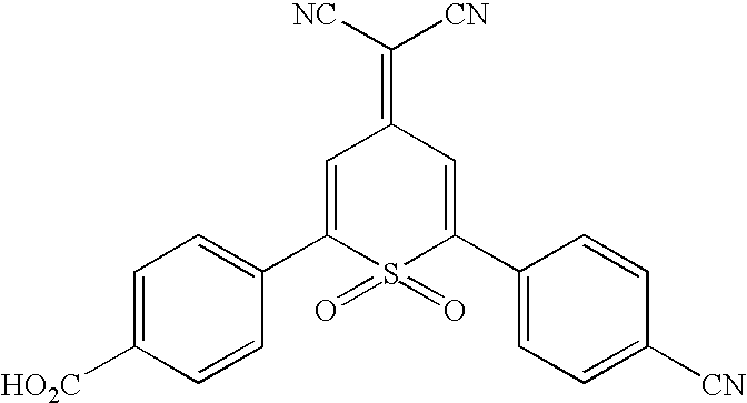 |
| I-5 |  |
| I-6 |  |
| I-7 |  |
| I-8 |  |
| I-9 |  |
| I-10 |  |
| I-11 |  |
| I-12 |  |
| I-13 |  |
| I-14 |  |
| I-15 |  |
| I-16 |  |
| I-17 |  |
| I-18 |  |
| I-19 |  |
| I-20 |  |
| I-21 |  |
| I-22 |  |
| I-23 |  |
| I-24 |  |
| I-25 |  |
| I-26 |  |
| I-27 |  |
| I-28 |  |
| I-29 |  |
| I-30 |  |
| I-31 |  |
| I-32 |  |
| I-33 |  |
| I-34 |  |
| I-35 |  |
| I-36 |  |
| I-37 |  |
| I-38 |  |
| I-39 |  |
| I-40 |  |
| I-41 |  |
| I-42 |  |
| I-43 |  |
| I-44 |  |
| I-45 |  |
| I-46 |  |
| I-47 |  |
| I-48 |  |
| I-49 |  |
| I-50 |  |
| I-51 |  |
| I-52 | 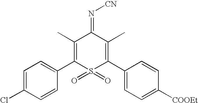 |
| I-53 |  |
| I-54 |  |
| I-55 |  |
| I-56 |  |
| I-57 |  |
| I-58 |  |
| I-59 |  |
| I-60 |  |
| I-61 |  |
| I-62 |  |
| I-63 |  |
| I-64 |  |
| I-65 |  |
| I-66 |  |
| I-67 |  |
| I-68 |  |
| I-69 |  |
| I-70 |  |
| I-71 |  |
Preferred compounds listed above include I-1 thru I-6, I-8 thru I-13, I-15 thru I-25, I-27 thru I-35, I-40, I-41, I-46, I-48, I-49. Additionally, compounds I-7, I-14, I-26, I-36 thru I-38, I-42 thru I-44, I-47, I-62 thru I-65, I-69 are preferred. More preferred compounds include I-39, I-66, I-67, I-68, I-50 thru I-61, I-70, I-71. The most preferred electrochromophores of the present invention include I-2, I-6, and I-8. In one preferred embodiment, the electrochromic material comprises electrochromic sulfone structures that have groups for linking to nanocrystalline TiO2 or SnO2.
| TABLE A |
| Reduction Potentials |
| Compound | Er (V vs SCE) | ||
| I-1 | −0.20 | ||
| I-9 | −0.39 | ||
| I-10 | −0.29 | ||
| I-20 | −0.19 | ||
| I-16 | −0.17 | ||
| I-15 | −0.23 | ||
| I-22 | −0.18 | ||
| I-13 | −0.40 | ||
| I-12 | −0.28 | ||
| I-17 | −0.21 | ||
| I-19 | −0.22 | ||
| I-24 | −0.19 | ||
| I-11 | −0.29 | ||
| I-2 | −0.22 | ||
| I-6 | −0.16 | ||
| I-8 | −0.48 | ||
| I-30 | −0.27 | ||
| I-27 | −0.23 | ||
| I-41 | −0.57 | ||
| TABLE B |
| Spectral data for 2,6-disubstituted-4H-1,1-dioxo-thiopyran |
| electrochromophores in acetonitrile solution |
| Neutral form | Anion radical form |
| λmax | extinction | λmax | extinction | |||
| Cpd | (nm) | color | (M−1 cm−1) | (nm) | color | (M−1 cm−1) |
| I-1 | 371 | yellow | 28,000 | 556 | purple | 18,000 |
| I-9 | 319 | colorless | 27,000 | 550 | magenta | 9,800 |
| I-10 | 333 | yellow | 27,000 | 528 | purple | 19,000 |
| I-2 | 380 | yellow | 21,000 | 553 | purple | 12,400 |
| I-6 | 347 | colorless | 26,200 | 558 | purple | 15,400 |
| I-8 | 265 | yellow | — | 712,490 | green | — |
| I-30 | 391 | yellow | 27,000 | 446,582 | green | 19,600 |
| I-27 | 360 | yellow | 18,100 | 556 | purple | 9,700 |
| I-41 | 316 | colorless | — | 546 | magenta | — |
Claims (81)


Priority Applications (6)
| Application Number | Priority Date | Filing Date | Title |
|---|---|---|---|
| US10/813,885 US7471437B2 (en) | 2004-03-31 | 2004-03-31 | Electrochromic materials and devices |
| EP05725697A EP1740672B1 (en) | 2004-03-31 | 2005-03-16 | Novel electrochromic materials and devices |
| JP2007506212A JP5096137B2 (en) | 2004-03-31 | 2005-03-16 | New electrochromic materials and equipment |
| CNA2005800108509A CN1938395A (en) | 2004-03-31 | 2005-03-16 | Novel electrochromic materials and devices |
| PCT/US2005/008696 WO2005100504A1 (en) | 2004-03-31 | 2005-03-16 | Novel electrochromic materials and devices |
| DE602005020762T DE602005020762D1 (en) | 2004-03-31 | 2005-03-16 | NEW ELECTROCHROME FABRICS AND DEVICES |
Applications Claiming Priority (1)
| Application Number | Priority Date | Filing Date | Title |
|---|---|---|---|
| US10/813,885 US7471437B2 (en) | 2004-03-31 | 2004-03-31 | Electrochromic materials and devices |
Publications (2)
| Publication Number | Publication Date |
|---|---|
| US20050219678A1 US20050219678A1 (en) | 2005-10-06 |
| US7471437B2 true US7471437B2 (en) | 2008-12-30 |
Family
ID=34962807
Family Applications (1)
| Application Number | Title | Priority Date | Filing Date |
|---|---|---|---|
| US10/813,885 Expired - Fee Related US7471437B2 (en) | 2004-03-31 | 2004-03-31 | Electrochromic materials and devices |
Country Status (6)
| Country | Link |
|---|---|
| US (1) | US7471437B2 (en) |
| EP (1) | EP1740672B1 (en) |
| JP (1) | JP5096137B2 (en) |
| CN (1) | CN1938395A (en) |
| DE (1) | DE602005020762D1 (en) |
| WO (1) | WO2005100504A1 (en) |
Cited By (6)
| Publication number | Priority date | Publication date | Assignee | Title |
|---|---|---|---|---|
| US20090027757A1 (en) * | 2005-05-31 | 2009-01-29 | Noriyuki Kokeguchi | Electrochromic display element and full-color electrochromic display element |
| US20120081773A1 (en) * | 2010-10-05 | 2012-04-05 | J Touch Corporation | Electrochromic unit and stereo image display device having the same |
| US8867116B1 (en) | 2013-03-15 | 2014-10-21 | Gentex Corporation | Distate electrochromic device |
| USD751786S1 (en) * | 2015-06-10 | 2016-03-15 | Kenneth L. Flickinger | Fishing cart |
| US20160152633A1 (en) * | 2011-12-27 | 2016-06-02 | Canon Kabushiki Kaisha | Novel organic compound |
| US20170242314A1 (en) * | 2014-11-06 | 2017-08-24 | Canon Kabushiki Kaisha | Organic electrochromic device, optical filter, lens unit, and imaging apparatus |
Families Citing this family (23)
| Publication number | Priority date | Publication date | Assignee | Title |
|---|---|---|---|---|
| FR2857759B1 (en) * | 2003-07-16 | 2005-12-23 | Saint Gobain | ELECTROCOMMANDABLE FILM WITH VARIABLE OPTICAL AND / OR ENERGY PROPERTIES |
| WO2007149090A1 (en) * | 2006-06-23 | 2007-12-27 | E. I. Du Pont De Nemours And Company | Amorphous polymers with pendant chromogenic groups |
| CN101432387B (en) * | 2006-06-23 | 2012-10-03 | 纳幕尔杜邦公司 | Electrochromic electrolyte blend |
| JP5284627B2 (en) * | 2007-11-27 | 2013-09-11 | 株式会社船井電機新応用技術研究所 | Electrochromic display device |
| JP5240499B2 (en) * | 2008-03-11 | 2013-07-17 | 株式会社リコー | Electrochromic material |
| KR20110133717A (en) * | 2010-06-07 | 2011-12-14 | 삼성전자주식회사 | Organic solar cell and method of manufacturing the same |
| CN102621759A (en) * | 2011-01-26 | 2012-08-01 | 介面光电股份有限公司 | Three-dimensional image display device and electrochromic module thereof |
| CN106662787B (en) * | 2014-08-04 | 2020-03-20 | 金泰克斯公司 | Electrochromic device |
| JP6623507B2 (en) * | 2014-08-26 | 2019-12-25 | 株式会社リコー | Electrochromic device |
| US11209713B2 (en) * | 2014-08-08 | 2021-12-28 | Ricoh Company, Ltd. | Electrochromic element and electrochromic dimming element |
| EP3177963B1 (en) * | 2014-08-08 | 2020-02-19 | Ricoh Company, Ltd. | Electrochromic element and electrochromic dimming element |
| US10183557B2 (en) * | 2015-09-22 | 2019-01-22 | Faraday & Future Inc. | Dimmable sunvisor |
| CN113075829A (en) * | 2016-03-07 | 2021-07-06 | 力海科技股份有限公司 | Electrochromic device |
| JP6885073B2 (en) * | 2016-05-11 | 2021-06-09 | 株式会社リコー | Electrochromic element |
| CN105954954B (en) * | 2016-06-23 | 2019-05-14 | 上海师范大学 | A kind of solid-state electrochromic device and the preparation method and application thereof |
| CN106249500B (en) * | 2016-08-25 | 2019-03-22 | 北京工业大学 | It is a kind of based on amorphous state-nanocomposite structure flexible electro-chromic device and preparation method thereof |
| JP7199868B2 (en) * | 2017-10-10 | 2023-01-06 | キヤノン株式会社 | Electrochromic device, optical filter, lens unit, imaging device, and window material |
| EP3953762B1 (en) * | 2019-04-09 | 2022-09-14 | Gentex Corporation | Low dimerizing viologen electrochromic compounds and devices |
| CN110028661B (en) * | 2019-04-24 | 2020-08-11 | 武汉华星光电半导体显示技术有限公司 | Polycarbonate, preparation method and application thereof |
| US11118010B2 (en) | 2019-04-24 | 2021-09-14 | Wuhan China Star Optoelectronics Semiconductor Display Technology Co., Ltd. | Polycarbonate, method for preparing thereof, and application thereof |
| JP2023544139A (en) * | 2020-09-29 | 2023-10-20 | ノームズ テクノロジーズ インコーポレイテッド | Cyclic sulfone additive for lithium batteries |
| CN112812427A (en) * | 2020-12-31 | 2021-05-18 | 苏州度辰新材料有限公司 | Photoluminescent color-changing polyolefin master batch and preparation method thereof |
| CN112817189A (en) * | 2021-03-05 | 2021-05-18 | 广东旗滨节能玻璃有限公司 | Electrochromic glass |
Citations (9)
| Publication number | Priority date | Publication date | Assignee | Title |
|---|---|---|---|---|
| US4324622A (en) * | 1974-09-26 | 1982-04-13 | American Cyanamid Company | Multilayered electroplatographic element comprising ion conductive and electrochromic layers |
| US4514481A (en) * | 1984-03-09 | 1985-04-30 | Eastman Kodak Company | 4H-Thiopyran-1,1-dioxide and electrophotographic layers and elements comprising same |
| US4902108A (en) | 1986-03-31 | 1990-02-20 | Gentex Corporation | Single-compartment, self-erasing, solution-phase electrochromic devices, solutions for use therein, and uses thereof |
| US5128700A (en) | 1989-05-12 | 1992-07-07 | Minolta Camera Kabushiki Kaisha | Camera capable of recording sounds relevant to the photographing |
| WO1997035227A2 (en) | 1996-03-15 | 1997-09-25 | Ecole Polytechnique Federale De Lausanne | Electrochromic or photoelectrochromic device |
| WO1998003267A1 (en) | 1996-07-23 | 1998-01-29 | Electrosols Ltd. | A dispensing device and method for forming material |
| WO1998035267A1 (en) | 1997-02-06 | 1998-08-13 | University College Dublin | Electrochromic system |
| WO2001027690A2 (en) | 1999-10-11 | 2001-04-19 | University College Dublin | Electrochromic device |
| US6433914B1 (en) | 1999-08-19 | 2002-08-13 | Gentex Corporation | Color-stabilized electrochromic devices |
Family Cites Families (3)
| Publication number | Priority date | Publication date | Assignee | Title |
|---|---|---|---|---|
| US5039585A (en) * | 1989-12-22 | 1991-08-13 | Eastman Kodak Company | Electrophotographic elements containing new electron-transport agents |
| US5500317A (en) * | 1994-06-16 | 1996-03-19 | Eastman Kodak Company | Electrophotographic elements containing soluble cyclic sulfone electron transport agents |
| JP3605776B2 (en) * | 1994-12-05 | 2004-12-22 | コニカミノルタホールディングス株式会社 | Electrophotographic photoreceptor |
-
2004
- 2004-03-31 US US10/813,885 patent/US7471437B2/en not_active Expired - Fee Related
-
2005
- 2005-03-16 CN CNA2005800108509A patent/CN1938395A/en active Pending
- 2005-03-16 JP JP2007506212A patent/JP5096137B2/en not_active Expired - Fee Related
- 2005-03-16 WO PCT/US2005/008696 patent/WO2005100504A1/en not_active Application Discontinuation
- 2005-03-16 DE DE602005020762T patent/DE602005020762D1/en active Active
- 2005-03-16 EP EP05725697A patent/EP1740672B1/en not_active Expired - Fee Related
Patent Citations (12)
| Publication number | Priority date | Publication date | Assignee | Title |
|---|---|---|---|---|
| US4324622A (en) * | 1974-09-26 | 1982-04-13 | American Cyanamid Company | Multilayered electroplatographic element comprising ion conductive and electrochromic layers |
| US4514481A (en) * | 1984-03-09 | 1985-04-30 | Eastman Kodak Company | 4H-Thiopyran-1,1-dioxide and electrophotographic layers and elements comprising same |
| US4902108A (en) | 1986-03-31 | 1990-02-20 | Gentex Corporation | Single-compartment, self-erasing, solution-phase electrochromic devices, solutions for use therein, and uses thereof |
| US5128700A (en) | 1989-05-12 | 1992-07-07 | Minolta Camera Kabushiki Kaisha | Camera capable of recording sounds relevant to the photographing |
| WO1997035227A2 (en) | 1996-03-15 | 1997-09-25 | Ecole Polytechnique Federale De Lausanne | Electrochromic or photoelectrochromic device |
| US20020181068A1 (en) | 1996-03-15 | 2002-12-05 | Pierre Bonhote | Electrochromic or photoelectrochromic device |
| WO1998003267A1 (en) | 1996-07-23 | 1998-01-29 | Electrosols Ltd. | A dispensing device and method for forming material |
| WO1998035267A1 (en) | 1997-02-06 | 1998-08-13 | University College Dublin | Electrochromic system |
| US6301038B1 (en) | 1997-02-06 | 2001-10-09 | University College Dublin | Electrochromic system |
| US6605239B2 (en) | 1997-02-06 | 2003-08-12 | University College Dublin | Electrochromic system |
| US6433914B1 (en) | 1999-08-19 | 2002-08-13 | Gentex Corporation | Color-stabilized electrochromic devices |
| WO2001027690A2 (en) | 1999-10-11 | 2001-04-19 | University College Dublin | Electrochromic device |
Non-Patent Citations (8)
| Title |
|---|
| "Electrochromic Materials", in Proceedings of the Electrochemical Society, K. Ho, C. Greenberg, D. MacArthur, eds., vol. 96-24, 1997, pp. 1-13, Pennington, NJ. |
| A. Sammells et. al., J. Electrochem. Soc., 1986, vol. 133, 1270-1271. |
| A. Schmidt, M.L. Anderson: "Electronic states of vapor deposited electron and hole transport agents and luminescent materials for light-emitting diodes", J.Appl.Phys., vol. 78, No. 9, Nov. 1, 1995, pp. 5619-5625, XP002334161. |
| Displays (1999) 20, pp. 137-144. |
| Fitzmaurice et. al, J. Phys. Chem. B 2000, vol. 104, 11449-1459. |
| Gratzel et. al. in J. Amer. Chem. Soc., 1993, vol. 115, 6382-6390. |
| Hisaya Sato, Hisaaki Matsuda: "Synthesis and characterization of electron transporting polymers having thioxznthene derivatives", Synthetic Metals, vol. 105, 1999, pp. 55-60, XP002334162. |
| N. Rowley and R. Mortimer, "New Electrochromic Materials", Science Progress (2002), 85 (3), 243-262. |
Cited By (9)
| Publication number | Priority date | Publication date | Assignee | Title |
|---|---|---|---|---|
| US20090027757A1 (en) * | 2005-05-31 | 2009-01-29 | Noriyuki Kokeguchi | Electrochromic display element and full-color electrochromic display element |
| US7619803B2 (en) * | 2005-05-31 | 2009-11-17 | Konica Minolta Holdings, Inc. | Electrochromic display element and full-color electrochromic display element |
| US20120081773A1 (en) * | 2010-10-05 | 2012-04-05 | J Touch Corporation | Electrochromic unit and stereo image display device having the same |
| US20160152633A1 (en) * | 2011-12-27 | 2016-06-02 | Canon Kabushiki Kaisha | Novel organic compound |
| US9611233B2 (en) * | 2011-12-27 | 2017-04-04 | Canon Kabushiki Kaisha | Organic compound |
| US8867116B1 (en) | 2013-03-15 | 2014-10-21 | Gentex Corporation | Distate electrochromic device |
| US20170242314A1 (en) * | 2014-11-06 | 2017-08-24 | Canon Kabushiki Kaisha | Organic electrochromic device, optical filter, lens unit, and imaging apparatus |
| US10372005B2 (en) * | 2014-11-06 | 2019-08-06 | Canon Kabushiki Kaisha | Organic electrochromic device, optical filter, lens unit, and imaging apparatus |
| USD751786S1 (en) * | 2015-06-10 | 2016-03-15 | Kenneth L. Flickinger | Fishing cart |
Also Published As
| Publication number | Publication date |
|---|---|
| EP1740672A1 (en) | 2007-01-10 |
| EP1740672B1 (en) | 2010-04-21 |
| DE602005020762D1 (en) | 2010-06-02 |
| JP5096137B2 (en) | 2012-12-12 |
| JP2007530768A (en) | 2007-11-01 |
| CN1938395A (en) | 2007-03-28 |
| WO2005100504A1 (en) | 2005-10-27 |
| US20050219678A1 (en) | 2005-10-06 |
Similar Documents
| Publication | Publication Date | Title |
|---|---|---|
| US7471437B2 (en) | Electrochromic materials and devices | |
| US10197881B2 (en) | Complimentary polymer electrochromic device | |
| US7633669B2 (en) | Durable electrooptic devices comprising ionic liquids | |
| US6853472B2 (en) | Electrolytes for electrooptic devices comprising ionic liquids | |
| Tahara et al. | Electrochromism of ferrocene-and viologen-based redox-active ionic liquids composite | |
| JP4541362B2 (en) | Reversible electrodeposition device and related electrochemical media | |
| CA2464451C (en) | Controlled diffusion coefficient electrochromic materials for use in electrochromic mediums and associated electrochromic devices | |
| CA2335270C (en) | Electrochromic media with concentration-enhanced stability, process for the preparation thereof and use in electrochromic devices | |
| US6310714B1 (en) | Color-stabilized electrochromic devices | |
| KR101534313B1 (en) | Electrochromic device including carbon-based material and viologen-based compound, and method for producing the same | |
| Monk et al. | Electrochromic materials and devices based on viologens | |
| WO2005026827A2 (en) | Durable electrooptic devices comprising ionic liquids | |
| US6388796B1 (en) | Electrochromic device having improved light stability | |
| JP2001194689A (en) | Electrochromic device having improved switching behavior | |
| JPH055906A (en) | Electrochromic display element | |
| KR19980013722A (en) | Electrochromic solution and electrochromic device using same |
Legal Events
| Date | Code | Title | Description |
|---|---|---|---|
| AS | Assignment |
Owner name: EASTMAN KODAK COMPANY, NEW YORK Free format text: ASSIGNMENT OF ASSIGNORS INTEREST;ASSIGNORS:LENHARD, JEROME R.;SHUKLA, DEEPAK;REEL/FRAME:015173/0821 Effective date: 20040331 |
|
| STCF | Information on status: patent grant |
Free format text: PATENTED CASE |
|
| CC | Certificate of correction | ||
| AS | Assignment |
Owner name: CITICORP NORTH AMERICA, INC., AS AGENT, NEW YORK Free format text: SECURITY INTEREST;ASSIGNORS:EASTMAN KODAK COMPANY;PAKON, INC.;REEL/FRAME:028201/0420 Effective date: 20120215 |
|
| FPAY | Fee payment |
Year of fee payment: 4 |
|
| AS | Assignment |
Owner name: WILMINGTON TRUST, NATIONAL ASSOCIATION, AS AGENT, Free format text: PATENT SECURITY AGREEMENT;ASSIGNORS:EASTMAN KODAK COMPANY;PAKON, INC.;REEL/FRAME:030122/0235 Effective date: 20130322 Owner name: WILMINGTON TRUST, NATIONAL ASSOCIATION, AS AGENT, MINNESOTA Free format text: PATENT SECURITY AGREEMENT;ASSIGNORS:EASTMAN KODAK COMPANY;PAKON, INC.;REEL/FRAME:030122/0235 Effective date: 20130322 |
|
| AS | Assignment |
Owner name: BANK OF AMERICA N.A., AS AGENT, MASSACHUSETTS Free format text: INTELLECTUAL PROPERTY SECURITY AGREEMENT (ABL);ASSIGNORS:EASTMAN KODAK COMPANY;FAR EAST DEVELOPMENT LTD.;FPC INC.;AND OTHERS;REEL/FRAME:031162/0117 Effective date: 20130903 Owner name: BARCLAYS BANK PLC, AS ADMINISTRATIVE AGENT, NEW YORK Free format text: INTELLECTUAL PROPERTY SECURITY AGREEMENT (SECOND LIEN);ASSIGNORS:EASTMAN KODAK COMPANY;FAR EAST DEVELOPMENT LTD.;FPC INC.;AND OTHERS;REEL/FRAME:031159/0001 Effective date: 20130903 Owner name: JPMORGAN CHASE BANK, N.A., AS ADMINISTRATIVE, DELAWARE Free format text: INTELLECTUAL PROPERTY SECURITY AGREEMENT (FIRST LIEN);ASSIGNORS:EASTMAN KODAK COMPANY;FAR EAST DEVELOPMENT LTD.;FPC INC.;AND OTHERS;REEL/FRAME:031158/0001 Effective date: 20130903 Owner name: PAKON, INC., NEW YORK Free format text: RELEASE OF SECURITY INTEREST IN PATENTS;ASSIGNORS:CITICORP NORTH AMERICA, INC., AS SENIOR DIP AGENT;WILMINGTON TRUST, NATIONAL ASSOCIATION, AS JUNIOR DIP AGENT;REEL/FRAME:031157/0451 Effective date: 20130903 Owner name: EASTMAN KODAK COMPANY, NEW YORK Free format text: RELEASE OF SECURITY INTEREST IN PATENTS;ASSIGNORS:CITICORP NORTH AMERICA, INC., AS SENIOR DIP AGENT;WILMINGTON TRUST, NATIONAL ASSOCIATION, AS JUNIOR DIP AGENT;REEL/FRAME:031157/0451 Effective date: 20130903 Owner name: JPMORGAN CHASE BANK, N.A., AS ADMINISTRATIVE, DELA Free format text: INTELLECTUAL PROPERTY SECURITY AGREEMENT (FIRST LIEN);ASSIGNORS:EASTMAN KODAK COMPANY;FAR EAST DEVELOPMENT LTD.;FPC INC.;AND OTHERS;REEL/FRAME:031158/0001 Effective date: 20130903 Owner name: BARCLAYS BANK PLC, AS ADMINISTRATIVE AGENT, NEW YO Free format text: INTELLECTUAL PROPERTY SECURITY AGREEMENT (SECOND LIEN);ASSIGNORS:EASTMAN KODAK COMPANY;FAR EAST DEVELOPMENT LTD.;FPC INC.;AND OTHERS;REEL/FRAME:031159/0001 Effective date: 20130903 |
|
| FPAY | Fee payment |
Year of fee payment: 8 |
|
| AS | Assignment |
Owner name: KODAK PORTUGUESA LIMITED, NEW YORK Free format text: RELEASE BY SECURED PARTY;ASSIGNOR:JP MORGAN CHASE BANK, N.A., AS ADMINISTRATIVE AGENT;REEL/FRAME:049814/0001 Effective date: 20190617 Owner name: EASTMAN KODAK COMPANY, NEW YORK Free format text: RELEASE BY SECURED PARTY;ASSIGNOR:JP MORGAN CHASE BANK, N.A., AS ADMINISTRATIVE AGENT;REEL/FRAME:049814/0001 Effective date: 20190617 Owner name: LASER PACIFIC MEDIA CORPORATION, NEW YORK Free format text: RELEASE BY SECURED PARTY;ASSIGNOR:JP MORGAN CHASE BANK, N.A., AS ADMINISTRATIVE AGENT;REEL/FRAME:049814/0001 Effective date: 20190617 Owner name: FPC, INC., NEW YORK Free format text: RELEASE BY SECURED PARTY;ASSIGNOR:JP MORGAN CHASE BANK, N.A., AS ADMINISTRATIVE AGENT;REEL/FRAME:049814/0001 Effective date: 20190617 Owner name: KODAK AMERICAS, LTD., NEW YORK Free format text: RELEASE BY SECURED PARTY;ASSIGNOR:JP MORGAN CHASE BANK, N.A., AS ADMINISTRATIVE AGENT;REEL/FRAME:049814/0001 Effective date: 20190617 Owner name: KODAK (NEAR EAST), INC., NEW YORK Free format text: RELEASE BY SECURED PARTY;ASSIGNOR:JP MORGAN CHASE BANK, N.A., AS ADMINISTRATIVE AGENT;REEL/FRAME:049814/0001 Effective date: 20190617 Owner name: KODAK AVIATION LEASING LLC, NEW YORK Free format text: RELEASE BY SECURED PARTY;ASSIGNOR:JP MORGAN CHASE BANK, N.A., AS ADMINISTRATIVE AGENT;REEL/FRAME:049814/0001 Effective date: 20190617 Owner name: KODAK PHILIPPINES, LTD., NEW YORK Free format text: RELEASE BY SECURED PARTY;ASSIGNOR:JP MORGAN CHASE BANK, N.A., AS ADMINISTRATIVE AGENT;REEL/FRAME:049814/0001 Effective date: 20190617 Owner name: KODAK REALTY, INC., NEW YORK Free format text: RELEASE BY SECURED PARTY;ASSIGNOR:JP MORGAN CHASE BANK, N.A., AS ADMINISTRATIVE AGENT;REEL/FRAME:049814/0001 Effective date: 20190617 Owner name: CREO MANUFACTURING AMERICA LLC, NEW YORK Free format text: RELEASE BY SECURED PARTY;ASSIGNOR:JP MORGAN CHASE BANK, N.A., AS ADMINISTRATIVE AGENT;REEL/FRAME:049814/0001 Effective date: 20190617 Owner name: FAR EAST DEVELOPMENT LTD., NEW YORK Free format text: RELEASE BY SECURED PARTY;ASSIGNOR:JP MORGAN CHASE BANK, N.A., AS ADMINISTRATIVE AGENT;REEL/FRAME:049814/0001 Effective date: 20190617 Owner name: KODAK IMAGING NETWORK, INC., NEW YORK Free format text: RELEASE BY SECURED PARTY;ASSIGNOR:JP MORGAN CHASE BANK, N.A., AS ADMINISTRATIVE AGENT;REEL/FRAME:049814/0001 Effective date: 20190617 Owner name: QUALEX, INC., NEW YORK Free format text: RELEASE BY SECURED PARTY;ASSIGNOR:JP MORGAN CHASE BANK, N.A., AS ADMINISTRATIVE AGENT;REEL/FRAME:049814/0001 Effective date: 20190617 Owner name: NPEC, INC., NEW YORK Free format text: RELEASE BY SECURED PARTY;ASSIGNOR:JP MORGAN CHASE BANK, N.A., AS ADMINISTRATIVE AGENT;REEL/FRAME:049814/0001 Effective date: 20190617 Owner name: PAKON, INC., NEW YORK Free format text: RELEASE BY SECURED PARTY;ASSIGNOR:JP MORGAN CHASE BANK, N.A., AS ADMINISTRATIVE AGENT;REEL/FRAME:049814/0001 Effective date: 20190617 |
|
| AS | Assignment |
Owner name: FPC INC., NEW YORK Free format text: RELEASE BY SECURED PARTY;ASSIGNOR:BARCLAYS BANK PLC;REEL/FRAME:052773/0001 Effective date: 20170202 Owner name: EASTMAN KODAK COMPANY, NEW YORK Free format text: RELEASE BY SECURED PARTY;ASSIGNOR:BARCLAYS BANK PLC;REEL/FRAME:052773/0001 Effective date: 20170202 Owner name: KODAK AMERICAS LTD., NEW YORK Free format text: RELEASE BY SECURED PARTY;ASSIGNOR:BARCLAYS BANK PLC;REEL/FRAME:052773/0001 Effective date: 20170202 Owner name: KODAK (NEAR EAST) INC., NEW YORK Free format text: RELEASE BY SECURED PARTY;ASSIGNOR:BARCLAYS BANK PLC;REEL/FRAME:052773/0001 Effective date: 20170202 Owner name: FAR EAST DEVELOPMENT LTD., NEW YORK Free format text: RELEASE BY SECURED PARTY;ASSIGNOR:BARCLAYS BANK PLC;REEL/FRAME:052773/0001 Effective date: 20170202 Owner name: KODAK PHILIPPINES LTD., NEW YORK Free format text: RELEASE BY SECURED PARTY;ASSIGNOR:BARCLAYS BANK PLC;REEL/FRAME:052773/0001 Effective date: 20170202 Owner name: NPEC INC., NEW YORK Free format text: RELEASE BY SECURED PARTY;ASSIGNOR:BARCLAYS BANK PLC;REEL/FRAME:052773/0001 Effective date: 20170202 Owner name: QUALEX INC., NEW YORK Free format text: RELEASE BY SECURED PARTY;ASSIGNOR:BARCLAYS BANK PLC;REEL/FRAME:052773/0001 Effective date: 20170202 Owner name: KODAK REALTY INC., NEW YORK Free format text: RELEASE BY SECURED PARTY;ASSIGNOR:BARCLAYS BANK PLC;REEL/FRAME:052773/0001 Effective date: 20170202 Owner name: LASER PACIFIC MEDIA CORPORATION, NEW YORK Free format text: RELEASE BY SECURED PARTY;ASSIGNOR:BARCLAYS BANK PLC;REEL/FRAME:052773/0001 Effective date: 20170202 |
|
| FEPP | Fee payment procedure |
Free format text: MAINTENANCE FEE REMINDER MAILED (ORIGINAL EVENT CODE: REM.); ENTITY STATUS OF PATENT OWNER: LARGE ENTITY |
|
| LAPS | Lapse for failure to pay maintenance fees |
Free format text: PATENT EXPIRED FOR FAILURE TO PAY MAINTENANCE FEES (ORIGINAL EVENT CODE: EXP.); ENTITY STATUS OF PATENT OWNER: LARGE ENTITY |
|
| STCH | Information on status: patent discontinuation |
Free format text: PATENT EXPIRED DUE TO NONPAYMENT OF MAINTENANCE FEES UNDER 37 CFR 1.362 |
|
| FP | Lapsed due to failure to pay maintenance fee |
Effective date: 20201230 |