US7471665B2 - Single transceiver architecture for a wireless network - Google Patents
Single transceiver architecture for a wireless network Download PDFInfo
- Publication number
- US7471665B2 US7471665B2 US11/800,543 US80054307A US7471665B2 US 7471665 B2 US7471665 B2 US 7471665B2 US 80054307 A US80054307 A US 80054307A US 7471665 B2 US7471665 B2 US 7471665B2
- Authority
- US
- United States
- Prior art keywords
- repeater
- data
- wireless
- channel
- repeaters
- Prior art date
- Legal status (The legal status is an assumption and is not a legal conclusion. Google has not performed a legal analysis and makes no representation as to the accuracy of the status listed.)
- Expired - Lifetime, expires
Links
Images


Classifications
-
- H—ELECTRICITY
- H04—ELECTRIC COMMUNICATION TECHNIQUE
- H04W—WIRELESS COMMUNICATION NETWORKS
- H04W88/00—Devices specially adapted for wireless communication networks, e.g. terminals, base stations or access point devices
- H04W88/08—Access point devices
-
- H—ELECTRICITY
- H04—ELECTRIC COMMUNICATION TECHNIQUE
- H04B—TRANSMISSION
- H04B7/00—Radio transmission systems, i.e. using radiation field
- H04B7/14—Relay systems
- H04B7/15—Active relay systems
- H04B7/155—Ground-based stations
- H04B7/15507—Relay station based processing for cell extension or control of coverage area
-
- H—ELECTRICITY
- H04—ELECTRIC COMMUNICATION TECHNIQUE
- H04B—TRANSMISSION
- H04B7/00—Radio transmission systems, i.e. using radiation field
- H04B7/14—Relay systems
- H04B7/15—Active relay systems
- H04B7/155—Ground-based stations
- H04B7/15528—Control of operation parameters of a relay station to exploit the physical medium
- H04B7/15542—Selecting at relay station its transmit and receive resources
-
- H—ELECTRICITY
- H04—ELECTRIC COMMUNICATION TECHNIQUE
- H04L—TRANSMISSION OF DIGITAL INFORMATION, e.g. TELEGRAPHIC COMMUNICATION
- H04L63/00—Network architectures or network communication protocols for network security
- H04L63/04—Network architectures or network communication protocols for network security for providing a confidential data exchange among entities communicating through data packet networks
- H04L63/0428—Network architectures or network communication protocols for network security for providing a confidential data exchange among entities communicating through data packet networks wherein the data content is protected, e.g. by encrypting or encapsulating the payload
-
- H—ELECTRICITY
- H04—ELECTRIC COMMUNICATION TECHNIQUE
- H04W—WIRELESS COMMUNICATION NETWORKS
- H04W88/00—Devices specially adapted for wireless communication networks, e.g. terminals, base stations or access point devices
- H04W88/02—Terminal devices
- H04W88/04—Terminal devices adapted for relaying to or from another terminal or user
-
- H—ELECTRICITY
- H04—ELECTRIC COMMUNICATION TECHNIQUE
- H04W—WIRELESS COMMUNICATION NETWORKS
- H04W16/00—Network planning, e.g. coverage or traffic planning tools; Network deployment, e.g. resource partitioning or cells structures
- H04W16/24—Cell structures
- H04W16/26—Cell enhancers or enhancement, e.g. for tunnels, building shadow
-
- H—ELECTRICITY
- H04—ELECTRIC COMMUNICATION TECHNIQUE
- H04W—WIRELESS COMMUNICATION NETWORKS
- H04W76/00—Connection management
- H04W76/20—Manipulation of established connections
Definitions
- the present invention relates generally to wireless networks, and more particularly to methods and apparatus for configuring, expanding and maintaining a wireless network for home or office use.
- wireless networks have emerged as flexible and cost-effective alternatives to conventional wired local area networks (LANs).
- LANs local area networks
- people are gravitating toward use of laptops and handheld devices that they can carry with them while they do their jobs or move from the living room to the bedroom.
- This has led industry manufacturers to view wireless technologies as an attractive alternative to Ethernet-type LANs for home and office consumer electronics devices, such as laptop computers, Digital Versatile Disk (“DVD”) players, television sets, and other media devices.
- wireless networks obviate the need for physical wires, they can be installed relatively easily.
- Wireless communication systems adapted for use in homes and office buildings typically include an access point coupled to an interactive data network (e.g., Internet) through a high-speed connection, such as a digital subscriber line (DSL) or cable modem.
- the access point is usually configured to have sufficient signal strength to transmit data to and receive data from remote terminals or client devices located throughout the building.
- a portable computer in a house may include a PCMCIA card with a wireless transceiver that allows it to receive and transmit data via the access point.
- Data exchanged between wireless client devices and access points is generally sent in packet format. Data packets may carry information such as source address, destination address, synchronization bits, data, error correcting codes, etc.
- Wired communication protocols for transmitting packets of information between wireless devices and access points have been adopted throughout the world.
- IEEE specification 802.11 and the Bluetooth wireless protocol have been widely used for industrial applications.
- IEEE specification 802.11, and Industrial, Scientific, and Medical (ISM) band networking protocols typically operate in the 2.4 GHz or 5 GHz frequency bands.
- HIPERLAN a standard known as HIPERLAN is widely used.
- the Wireless Asynchronous Transfer Mode (WATM) standard is another protocol under development. This latter standard defines the format of a transmission frame, within which control and data transfer functions can take place.
- the format and length of transmission frames may be fixed or dynamically variable.
- High-bandwidth data transmissions can be degraded by the presence of structural obstacles (e.g., walls, floors, concrete, multiple stories, etc.), large appliances (e.g., refrigerator, oven, furnace, etc.), human traffic, conflicting devices (e.g., wireless phones, microwave ovens, neighboring networks, X10 cameras, etc.), as well as by the physical distance between the access point and the mobile terminal or other device.
- structural obstacles e.g., walls, floors, concrete, multiple stories, etc.
- large appliances e.g., refrigerator, oven, furnace, etc.
- conflicting devices e.g., wireless phones, microwave ovens, neighboring networks, X10 cameras, etc.
- an IEEE 802.11b compliant wireless transceiver may have a specified data rate of 11.0 megabits per second (Mbps), but the presence of walls in the transmission path can cause the effective data rate to drop to about 1.0 Mbps or less. Degradation of the video signal can also lead to repeated transmission re-tries, causing the video image to appear choppy.
- D-Link Systems, Inc. manufactures a 2.4 GHz wireless product that can be configured to perform either as a wireless access point, as a point-to-point bridge with another access point, as a point-to-multi-point wireless bridge, as a wireless client, or as a wireless repeater.
- the product functions to re-transmit packets received from a primary access point.
- the problem with these types of wireless repeaters is that they retransmit at the same frequency as the primary access point device. Consequently, because the primary access point and repeaters share the same channel, the bandwidth of the network is effectively reduced for each repeater installed.
- Still another attempted solution to the problem of wireless transmission of video data is to lower the bandwidth of the video through data compression.
- This technique involves compressing the video data prior to transmission, then decompressing the data after it has been received.
- the main drawback with compression/decompression techniques is that they tend to compromise the quality of the video image, which is unacceptable to most viewers. This approach also suffers from the problem of lost connections during transmission.
- FIG. 1 is a conceptual diagram of a wireless network according to one embodiment of the present invention.
- FIGS. 2A & 2B illustrate propagation characteristics for access points operating in the 2.4 GHz and 5 GHz frequency bands.
- FIG. 3 is an example of wireless signal repeating in accordance with one embodiment of the present invention.
- FIG. 4 is a chart illustrating pipelined data packet flow from source to destination in accordance with one embodiment of the present invention.
- FIG. 5 is an example showing limitless data transmission range extension in accordance with another embodiment of the present invention.
- FIG. 6 is an example of wireless signal repeating for 2.4 GHz traffic utilizing a 5 GHz repeater backbone in accordance with another embodiment of the present invention.
- FIG. 7 is a chart illustrating pipelined data packet flow from source to destination in accordance with the embodiment of FIG. 6 .
- FIG. 8 is an example of wireless signal repeating for 2.4 GHz traffic utilizing a 5 GHz repeater backbone, with the source and destination on the same channel in accordance with yet another embodiment of the present invention.
- FIG. 9 is a chart illustrating pipelined data packet flow from source to destination in accordance with the embodiment of FIG. 8 .
- FIG. 10 is a perspective view of a wireless repeater in accordance with one embodiment of the present invention.
- FIG. 11 is a circuit block diagram of the internal architecture of the wireless repeater shown in FIG. 10 .
- FIG. 12 illustrates three repeaters configured in a wireless network according to one embodiment of the present invention.
- FIG. 13 is a diagram that shows the unlimited range at full bandwidth range of one embodiment of the present invention.
- FIGS. 14A & 14B show a plan view and a side elevation view, respectively, of a floor plan for a building installed with a wireless network according to one embodiment of the present invention.
- FIG. 14C illustrates the repeater topology for the first floor shown in FIGS. 14A & 14B .
- FIGS. 15A & 15B show plan and side elevation views, respectively, of the wireless network of FIGS. 14A & 14B , but with a disturbance.
- FIGS. 16A & 16B illustrate the network of FIGS. 15A and 15B after reconfiguration to overcome the disturbance.
- FIGS. 17A & 17B illustrate another example of channel conflict in a wireless network implemented according to one embodiment of the present invention.
- FIGS. 18A & 18B illustrate the network of FIGS. 17A and 17B after channel reconfiguration.
- FIG. 19 is a floor plan showing two simultaneous wireless networks operating in a building according to one embodiment of the present invention.
- FIG. 20 shows a wireless network according to another embodiment of the present invention.
- FIG. 21 is a circuit block diagram of the basic architecture of a DBS tuner according to one embodiment of the present invention.
- FIG. 22 is a circuit block diagram of the basic architecture of a cable television tuner in accordance with one embodiment of the present invention.
- FIG. 23 is a circuit block diagram of the basic architecture of a wireless receiver in accordance with one embodiment of the present invention.
- FIG. 24 is an architectural block diagram of a wireless repeater according to another embodiment of the present invention.
- FIG. 25 is an architectural block diagram of a wireless receiver in accordance with another embodiment of the present invention.
- FIGS. 26A & 26B illustrate a prior art approach to access point transmission repeating.
- FIGS. 27A & 27B show examples of access point repeating in a network utilizing two repeaters in accordance with one embodiment of the present invention.
- FIGS. 28A & 28B show examples of access point repeating in a network utilizing three repeaters in accordance with another embodiment of the present invention.
- FIGS. 29A-29F illustrate an exemplary transaction across a wireless network utilizing non-access point repeaters in accordance with yet another embodiment of the present invention.
- FIGS. 30A-30F illustrate an exemplary transaction across a wireless network utilizing access point repeaters in accordance with still another embodiment of the present invention.
- FIG. 31 is an architectural block diagram of a wireless repeater according to yet another embodiment of the present invention.
- FIGS. 32A & 32B is another illustration showing propagation characteristics for access points operating in the 2.4 GHz and 5 GHz frequency bands.
- FIG. 33A is an example of wireless signal repeating in accordance with another embodiment of the present invention.
- FIG. 33B is a chart illustrating pipelined data packet flow from source to destination in accordance with the embodiment of FIG. 33A .
- FIG. 34A is an example of wireless signal repeating in accordance with still another embodiment of the present invention.
- FIG. 34B is a chart illustrating pipelined data packet flow from source to destination in accordance with the embodiment of FIG. 34A .
- FIG. 35A is an example of wireless signal repeating in accordance with yet another embodiment of the present invention.
- FIG. 35B is a chart illustrating pipelined data packet flow from source to destination in accordance with the embodiment of FIG. 35A .
- FIG. 36A is an example of wireless signal repeating in accordance with a further embodiment of the present invention.
- FIG. 36B is a chart illustrating pipelined data packet flow from source to destination in accordance with the embodiment of FIG. 36A .
- FIG. 37A is an example of wireless signal repeating in accordance with another embodiment of the present invention.
- FIG. 37B is a chart illustrating pipelined data packet flow from source to destination in accordance with the embodiment of FIG. 37A .
- the present invention is a wireless local area network (WLAN) that utilizes cellular techniques to extend the range of transmission without degrading bandwidth.
- WLAN wireless local area network
- the wireless network of the present invention is thus ideally suited for transmitting video programs (e.g., digitally-encoded video broadcast services, pay-per-view television, on-demand video services, etc.) throughout a house or other building, thereby creating a “media-live” environment.
- video programs e.g., digitally-encoded video broadcast services, pay-per-view television, on-demand video services, etc.
- a wireless home media network 10 comprises a source video access point 11 coupled to a broadband connection.
- the broadband connection may provide video content from a Direct Broadcast Satellite (DBS) or digital cable service provider.
- DBS Direct Broadcast Satellite
- Additional wireless access points may be physically located in a distributed manner throughout the home or building to provide connectivity among a variety of home media devices configured for wireless communications. As shown in FIG.
- these home media devices may include a laptop personal computer 12 , DVD player 13 , wireless-ready television 14 , and wireless-linked receiver 15 coupled to either a standard definition or high-definition television (SDTV/HDTV) 16 .
- SDTV/HDTV standard definition or high-definition television
- Other types of devices such as personal digital assistants (PDAs), may also be coupled to network 10 for receiving and/or transmitting data.
- PDAs personal digital assistants
- Practitioners in the art will appreciate that many client media devices such as personal computers, televisions, PDAs, etc., have the capability of detecting the operating frequency of the access point within a particular micro-cellular transmission range.
- wireless network 10 provides reliable, full home coverage at throughputs supporting multiple simultaneous video streams, e.g., two HDTV streams at approximately 30 Mbps; eight SDTV streams at about 16 Mbps.
- a plurality of access points is utilized in a wireless network to provide relatively short transmission ranges that preserve bandwidth and achieve high reliability.
- the wireless network of the present invention implements a three-dimensional (“3-D”) topology in which communications between an access point and mobile terminals or client media devices in a particular region occur at a frequency which is different than the communication frequency of a neighboring region.
- the 2.4 GHz and 5 GHz frequency bands are utilized for wireless transmissions.
- the 2.4 GHz band provides three non-overlapping channels
- the 5 GHz band provides twelve non-overlapping channels for simultaneous transmission traffic.
- the wireless network of the present invention achieves full range coverage in the home without bandwidth loss by utilizing a different channel for each data packet hop. This feature allows repeater data packets to overlap in time, as discussed in more detail below.
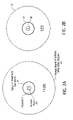
- FIG. 2A is a diagram illustrating the two-dimensional propagation characteristics through open air associated with an access point 20 operating in the 2.4 GHz band and transmitting on a particular channel, i.e., channel 1 .
- Inner circle 21 represents the range of maximum bandwidth
- outer circle 22 represents the range at which the signal from access point 20 ceases to interfere with other signals in the same channel.
- FIG. 2B shows an access point 30 operating in the 5 GHz band with maximum bandwidth and interference ranges represented by circles 31 and 32 , respectively.
- both access points 20 and 30 have a relatively short range at maximum bandwidth, but have a fairly wide interfering signal range.
- access point 30 has a shorter interference range than access point 20 .
- FIG. 3 is an example of wireless signal repeating in accordance with one embodiment of the present invention.
- each of the access points 20 a - 20 c transmits on a different channel.
- access point 20 a is shown operating on channel # 1 in the 2.4 GHz band;
- access point 20 b operates on channel # 6 ;
- access point 20 c operates on channel # 11 in the same band.
- the inner circles 21 a - 21 c each denotes the ranges of maximum bandwidth associated with access points 20 a - 20 c, respectively.
- each of the access points is advantageously located at a distance within the maximum bandwidth range of its nearest neighboring access point.
- the destination media device 25 is disposed within the maximum bandwidth range of its nearest access point 20 c.
- access points 20 b and 20 c function as signal repeaters to facilitate transmission of data from source access point 20 a to destination device 25 .
- each of the access points 20 a - 20 c repeats transmission of data packets on a different frequency channel than any of its neighboring access points within signal interference range. Access points located beyond the interference range of a channel may reuse that same channel.
- a source data packet 1 is transmitted by access point 20 a on channel # 1 .
- Access point 20 b repeats transmission of this data packet on channel # 6 .
- Access point 20 c again repeats transmission of data packet 1 ; this time on channel # 11 .
- Destination media device 25 receives data packet 1 from access point 20 c on channel # 11 .
- access point 20 a may immediately transmit a second source data packet (“packet 2 ”), followed by a third source data packet, a fourth data packet, and so on.
- Packet 2 a second source data packet
- packet 3 a third source data packet
- fourth data packet a fourth data packet
- Each of these data packets are repeated across the network in a pipeline manner by access points 20 b and 20 c, as shown in FIG. 4 .
- Pipelining of data packets across channels facilitates transmission of video data without loss of bandwidth.
- the wireless network of the present invention has no limitation on how far the transmission of data can extend, as long as there are a sufficient number of channels available.
- each hop normally can extend about 50 feet at maximum bandwidth, three hops on three different channels (one source plus two repeaters) can cover a distance of about 150 feet from source to destination.
- the license-free 5 GHz band e.g., 5725 MHz to 5850 MHz
- each hop in the 5 GHz band will typically extend about 50 feet at maximum bandwidth, but the large number of channels permits hops to extend indefinitely. That is, in a wireless network operating in the 5 GHz band according to the present invention, repeaters extend far enough for channel reuse. This means that hops can extend the range of transmission from source to destination without limitation.
- FIG. 5 is an example showing a network configuration in which each hop extends about 50 feet, so that ten hops cover about 500 feet.
- any channel beyond its interference range may be reused.
- the smaller inner circles representing the range of maximum bandwidth around the access points that operate on the same channel frequency e.g., channel # 1
- channel # 1 the same channel frequency
- each access point is shown spaced-apart from its nearest neighboring access point by a distance less than the maximum bandwidth range (i.e., small circle) of its nearest neighbor.
- any two access points transmitting on the same channel are shown separated from each by a distance greater than the interference signal range.
- Access points that re-use the same channel are separated by a distance greater than their respective signal interference ranges.
- the large spatial separation between access points using the same frequency channel means that transmission problems due to channel interference between access points operating on the same channel are virtually nonexistent in the wireless network of the present invention.
- different frequency bands may also be used during data transmission across the wireless network of the present invention.
- 5 GHz repeaters may be utilized to form an arbitrary length backbone for 2.4 GHz data traffic. This situation is illustrated in the example of FIGS. 6 & 7 , which shows source access point 40 a transmitting data packets to a 2.4 GHz destination 55 using 5 GHz repeaters 40 b & 40 c. Note that source point 40 a and repeater 40 d (transmitting to destination device 55 ) both operate in the 2.4 GHz band, but utilize different channels, i.e., channels # 6 and # 11 , respectively, to prevent bandwidth loss.
- Another possibility is to use a 5 GHz device at the destination and a 2.4 GHz access point at the source or vice-versa.
- the network is configured for communications with source-to-destination frequency band transitions of 2.4 GHz to 5 GHz, or 5 GHz to 2.4 GHz, or 2.4 GHz to 2.4 GHz on different channels (all utilizing 5 GHz for repeaters in-between), the network can provide an arbitrary length backbone for 2.4 gigahertz traffic, despite the fact there are only three 2.4 GHz channels available.
- the wireless network of the present invention is not limited to data transmissions confined to a single frequency band.
- a wireless network in accordance with the present invention where the source and destination devices both operate at 2.4 GHz using the same channel.
- Such an embodiment is shown in the conceptual diagram of FIG. 8 and the associated transmission chart of FIG. 9 , wherein source access point 40 a and repeater 40 d associated with destination media device 55 both operate in the 2.4 GHz band on channel # 6 .
- Repeaters 40 b and 40 c operate in the 5 GHz band on channel # 1 and # 2 , respectively.
- this particular embodiment has a penalty of 50% bandwidth loss, the network still may be extended to arbitrary length with no additional bandwidth loss, regardless of the total distance covered. It is appreciated that the 50% bandwidth loss in this embodiment results from the need to stagger the data packet transmissions, as shown in the chart of FIG. 9 , to avoid interference between the packet transmission by access point 40 a and the packet transmission by repeater 40 d.
- FIG. 11 is a circuit block diagram of the internal architecture of repeater unit 60 .
- Repeater unit 60 comprises a transformer/power supply 61 that provides supply voltages to the various internal electronic components, which include a CPU 62 , a RAM 63 , a Flash ROM 64 , and input/output application specific integrated circuitry (I/O ASIC) 66 , each of which is shown coupled to a system bus 65 .
- I/O ASIC input/output application specific integrated circuitry
- transceivers 74 - 76 are Also coupled to system bus 65 .
- transceivers 74 - 76 are coupled to an antenna 77 . Additional transceivers operating at different frequencies may be included in repeater unit 60 .
- CPU 62 controls the re-transmission of the received data packets, utilizing RAM 63 for both program execution, and for buffering of the packets as they are received from the upstream side, i.e., nearest the source, before they are sent out to the downstream side, i.e., toward the destination.
- Flash ROM 64 may be used to hold software and encryption key information associated with secure transmissions, for example, to insure that the network users are authorized users of satellite or cable subscriber services.
- a 1394 connector interface 70 provides a Firewire® port (coupled through a 1394 PHY physical interface 73 ) to I/O ASIC 66 . Also coupled to I/O ASIC 66 is a pushbutton switch 69 and an LED indicator panel 71 . Pushbutton switch 69 may be utilized in conjunction with interface 70 to authenticate repeater unit 60 for use in the network after the wireless receiver or source access point has been initially installed.
- FIG. 10 further shows that the upstream repeater in the network comprises a wireless transceiver that operates in compliance with IEEE specification 802.11a to run with an effective throughput of 36 Mbps utilizing large packets of approximately 2500 bytes each.
- IEEE 802.11a is a standard that permits use at more than one channel at a time.
- 802.11a wireless transceiver that operates on a different frequency channel. It should be understood that the present invention is not limited to these particular transceiver types or frequency bands.
- transceivers may utilize other types of transceivers; for instance, transceivers that operate in compliance with specifications that are compatible with IEEE specification 802.11a, 802.11b, or 802.11g, or which otherwise provide for wireless transmissions at high-bandwidths.
- IEEE specification 802.11a, 802.11b, 802.11g, and Industrial, Scientific, and Medical (ISM) band networking protocols are denoted as “802.11x”.
- Non-ISM bands wireless network protocols could be utilized as well.
- the network of the present invention could be implemented using transceivers compatible with HIPERLAN2, which runs with an effective throughput of about 42 Mbps.
- each wireless repeater may provide wireless communications to one or more local devices.
- FIG. 12 illustrates three repeaters 60 a - 60 c configured in a network wherein each repeater may provide a communication link to nearby wireless devices, such as laptop computers or wireless televisions, etc.
- Repeater units 60 may be installed in the wireless network of the present invention after the source access point (e.g., source video receiver) has been made operational.
- a new repeater unit 60 is first connected to the source access point or an existing repeater (one that is already plugged into an outlet and coupled to the wireless network) using a Firewire cable.
- the Firewire cable is connected between the existing repeater or source access point and the new repeater.
- Power is provided over the Firewire cable from the existing repeater or access point to the new repeater to activate the internal circuitry of the new repeater, so that encryption key information may be exchanged to allow the new repeater to securely connect to the network.
- Execution of program instructions for the exchange of encryption information may be initiated by the person performing the installation pressing pushbutton switch 69 , located on the front side of repeater unit 60 in FIG. 10 .
- the Firewire cable between the two devices may be disconnected.
- the repeater unit with the newly activated encryption key may then be plugged into an electrical outlet in any location of the home or building where the user wants the network to extend.
- LED indicator panel 71 provides an indication of transmission signal strength to the upstream receiver, and may be advantageously used to locate repeater unit 60 to extend the network in a home or building. If, for example, the LED output indicates a strong signal, the installer may wish to remove the repeater unit from its present wall outlet location to a location farther away from the nearest existing repeater or access point. If, upon moving to a new location, LED indicator panel 71 outputs a “weak” or a “no signal” reading, this means that the new repeater is too far away from existing connection points of the network. In either case, the installer should move the repeater unit back closer to an existing repeater or access point until a “good” or “strong” signal strength is indicated.
- Another option is to provide an audio indication of the transmission signal quality, instead of a visual indication.
- the source access point e.g., video receiver
- the source access point detects the presence a newly-activated repeater unit, it automatically self-configures the cellular repeater wireless network. This aspect of the present invention will be explained in greater detail below.
- the example network shown in FIG. 13 illustrates the unlimited range at full bandwidth feature of one embodiment of the present invention.
- a video access point 80 is shown running at 36 Mbps to transmit information and video data downstream to a destination television 81 containing a wireless receiver located in a distant room.
- the video data may originate from a data service connection, such as a Direct Broadcast Satellite (DBS), DSL, or cable television (CATV), provided to access point 80 .
- DBS Direct Broadcast Satellite
- CATV cable television
- Repeaters 60 a and 60 b function as intermediary access points to distribute the video content to client media devices in their local vicinity and to repeat downstream data packets received on the upstream side. As can be seen, each repeater transmits at 36 Mbps so the effective throughput received at destination television 81 remains at 36 Mbps, i.e., without bandwidth loss.
- FIGS. 14A & 14B show a plan view and a side elevation view, respectively, of a floor plan of a building 84 installed with four separate, secure wireless networks according to one embodiment of the present invention.
- FIG. 14C illustrates the repeater topology for the network installed on the first floor plan shown in FIGS. 14A & 14B .
- Source access points e.g., video tuners or data routers
- Additional access points i.e., repeaters
- squares with the number inside the square similarly designating the channel used for signal transmissions.
- each source access point 85 - 88 is shown connected to a broadband network (e.g., cable, DSL, etc.), with each source access points functioning as a broadband tuner/router.
- a broadband network e.g., cable, DSL, etc.
- each source access points functioning as a broadband tuner/router.
- four separate wireless networks are shown installed on separate floors of building 84 .
- access point 85 transmits video data packets on channel # 1 to repeaters 91 and 92 , which then both repeat the received data packets on channel # 2 .
- Repeaters 93 and 94 (both on channel # 3 ) are shown branching off of repeater 91 .
- Repeater 95 (channel # 4 ) is coupled to the network through repeater 93 .
- Repeater 96 (channel # 4 ) branches off of repeater 94 ;
- repeater 97 channel # 1 ) branches off of repeater 96 ; and repeater 98 (channel # 2 ) branches off of repeater 97 to complete the first floor topology.
- repeater 97 is able to reuse channel # 1 since it is located a relatively far distance from source access point 85 , which uses the same channel. Additionally, the side elevation view of FIG. 14B shows there are no devices on the second floor network above repeater 97 that use channel # 1 . For the same reasons, repeater 98 is able to reuse channel # 2 .
- access point 85 only needs one transceiver to create the repeating wireless network shown in FIGS. 14A-14C .
- the internal transceiver of access point 85 transmits on channel # 1 , which transmission is then received by the upstream transceivers of repeaters 91 and 92 .
- Repeater 91 transmits using its downstream transceiver on channel # 2 , which is then picked up by the two upstream transceivers of repeaters 93 and 94 , each of which, in turn, transmits on their downstream transceiver to repeaters 95 and 96 , respectively, and so on.
- access point 98 only transmits downstream to destination media devices, not to another access point. That is, access point 98 does not function as a repeater; rather, access point 98 simply communicates with the destination media devices in its local area.
- each access point in the topology tree does not need an arbitrary number of transceivers to repeat data messages across the network; an upstream transceiver and a downstream transceiver suffices.
- an additional 2.4 GHz band transceiver may be included, for example, to provide communications with 802.11b or 802.11g compatible devices. It should be understood, however, that there is no specific limit on the number or type of transceivers incorporated in the access points or repeaters utilized in the wireless network of the present invention.
- the tree structure of the wireless network of the present invention is well-suited to applications in which most of the bandwidth is provided from a single source (e.g., a satellite or cable feed).
- a single source e.g., a satellite or cable feed.
- the repeaters disposed in the branches the tree topology can share channels.
- the repeaters in the tree structure have to operate on different channels, in case a message travels from one branch to another branch of the tree.
- a processor in the source access point executes a program or algorithm that determines an optimal set of frequency channels allocated for use by each access point or repeater.
- An optimal set of channels is one that does not include over-lapping channels and avoids channels used by other interfering devices in the same locality.
- An optimal channel configuration may also be selected that maximizes channel re-use. Further, once a set of the channels has been chosen for use by the access points, modulated power can be reduced to the minimum needed to achieve maximum bandwidth across each link so as to reduce signal reflections.
- the wireless network of the present invention may also adapt to changes to the network by reconfiguring the channel assignments, such as when new repeaters are added, existing ones removed, or when the network experiences disturbances caused by other interfering devices (e.g., from a neighboring network).
- the first floor wireless network has been configured such that the channels used by each of the access points do not interfere with other devices located on other floors of building 84 .
- the side elevation view of FIG. 14B shows that interference sources are present in the upper stories of building 84 above the wireless network created by source access point 85 .
- the first floor network has configured itself to use channel # 1 , # 2 , # 3 and # 4 .
- the circuitry for controlling the self-configuration process may either be centralized in the source access point or distributed throughout the access points comprising the wireless network. In either case, the system may proceed through a process of iteration, wherein every possible combination of channels allocated to the access points may be tried in order to find an optimal combination of frequency channels. In one embodiment, the network hops through the frequency channels automatically so that an optimal combination of frequencies may be determined. Within a matter of seconds, the network may complete iterating through all permutations of channels to identify which combination of frequencies produces the best result.
- One example of a best result is the highest average bandwidth from source to each destination. Another best result may be defined as one which optimizes bandwidth to certain destination devices. For instance, if a particular destination device (e.g., a video receiver) requires higher bandwidth than other destination devices, then allocation of channels may be optimized to provide higher bandwidth in the network path to the particular destination device at the expense of lower bandwidth to other devices.
- the system of the present invention also functions to keep modulated power in the network to a minimum. It may be necessary in some instances, for example when transmitting through many walls to a maximum range, to use a lot of power. In other instances, a repeater is located nearby and there may be few walls to transmit through, so less transmission power is required.
- the access points may transmit at maximum power to establish a maximum range of communication. However, once communications have been established with all of the repeaters in the network, the power output may be reduced to a level that provides adequate signal transmission characteristics (i.e., a threshold signal strength), but no more. In other words, the network may throttle power output, keeping it only as high as it needs to be to create a strong signal to the next repeater.
- One benefit of such an operation is that it reduces signal reflections that may interfere with the reception quality. Another benefit is less power consumption.
- Another benefit of the power management feature of the present invention is that by having a given channel prorogate less distance, you create the opportunity to reuse that channel in the network at an earlier point in the topology than if transmissions were at maximum power.
- the wireless network of the present invention automatically detects channel conflicts that arise, and adapts the network to the conflict by reconfiguring itself to avoid the conflict. That is, the access points monitor the signal quality of the wireless transmissions on a continual basis. Any disturbance or conflict that causes signal transmissions to fall below an acceptable quality level may trigger an adaptive reconfiguration process.
- FIGS. 15A and 15B show plan and side elevation views, respectively, of the wireless network previously shown in FIGS. 14A & 14B , but with a disturbance generated by the activation of a cordless phone (shown by square 101 operating on channel # 2 ) in building 84 .
- the interference caused by cordless phone 101 is within the range of repeaters 91 and 92 , thereby affecting the transmissions of those repeaters.
- the network automatically detects the channel conflict and reconfigures itself to overcome the interference.
- FIGS. 16A and 16B illustrate the network of FIGS. 15A and 15B after reconfiguration to overcome the channel conflict caused by cordless phone 101 .
- building 84 is populated with many existing channels in use. Because of the channel usage in the upper stories, the network cannot simply swap out the channels used by repeaters 91 & 92 with a different one. Instead, in this example, the wireless network of the present invention replaces channel # 1 of source access point 85 with channel # 5 . That permits channel # 1 to replace channel # 2 in both repeaters 91 & 92 . In addition, because the channel # 1 usage by repeaters 91 & 92 would be too close to the channel # 1 usage by repeater 97 (see FIGS.
- the wireless network also replaces channel # 1 of repeater 97 with channel # 8 .
- channel # 8 can be used for repeater 97 because its only other use in building 84 is on the fourth floor at the opposite end of the structure.
- Repeater 98 is also shown reconfigured to use channel # 1 instead of channel # 2 .
- the adaptation process discussed above may be performed in a similar manner to the self-configuration process previously described. That is, all of the different possible combinations of channels may be tried until the network identifies an optimal combination that works to overcome the channel conflict without creating any new conflicts.
- the adaptation process may rely upon an algorithm that does not attempt to change or move channels which have already been established. In the example of FIGS. 16A and 16B , for instance, channel # 3 , used by repeaters 93 & 94 , and channel # 4 , used by repeaters 95 & 96 , are left in place. In other words, regardless of the origin of a channel conflict, the network of the present invention adapts to the disturbance by reconfiguring itself to optimize performance.
- the wireless network of the present invention can reduce bandwidth and still maintain connectivity.
- FIGS. 17A & 17B and FIGS. 18A & 18B Such a scenario is depicted in FIGS. 17A & 17B and FIGS. 18A & 18B .
- FIGS. 17A & 17B illustrate the conflict previously shown in FIGS. 15A & 15B , wherein a cordless phone 101 is activated, except with an additional channel conflict created by a wireless camera 102 operating on channel # 5 .
- the network has adapted by reusing the same channel in consecutive branches of the repeater topology, as shown in FIGS. 18A & 18B .
- FIGS. 18A & 18B show the reconfigured wireless network with repeaters 91 and 92 using channel # 3 . Because repeaters 93 and 94 also operate on channel # 3 the bandwidth of the network is reduced by 50%.
- simultaneous wireless networks may be created to run at the same time. Simultaneous wireless networks may be desirable in certain applications, say, where there are three HDTV sets each operating at 15 Mbps. If the backbone of the primary network operates at 36 Mbps, the available bandwidth is insufficient to accommodate all three screens.
- the solution provided by the present invention is to install a second video tuner (i.e., a second source access point) and double up the number of repeaters through each branch of the rest of the topology.
- FIG. 19 is a floor plan showing two simultaneous wireless networks operating in a building 84 to increase bandwidth. Such an arrangement is ideally suited to support multiple HDTV video streams.
- access points 110 and 120 each comprise a wireless video tuner or router with a broadband connection. Access point 110 is shown operating on channel # 1 and access point 120 is shown operating on channel # 5 . In this case, separate paths are created to the upper left and lower left sections of the floor plan.
- the path from access point 110 includes repeaters 111 , 112 and 113 on respective channels # 2 , # 3 and # 4 . Meanwhile, the path from access point 120 is implemented using repeaters 121 , 122 , 123 , 124 and 125 on channels # 6 , # 7 , # 8 , # 9 and # 10 , respectively.
- bandwidth can be increased arbitrarily in the arrangement of FIG. 19 .
- three, four, or more simultaneously running wireless networks may be implemented in a home or office environment to arbitrarily increase bandwidth to meet increasing data rate demands. If an adequate number of channels is available (e.g., allowing extension of the network across a sufficient distance for channel reuse), there is no limitation on the bandwidth that can be achieved in accordance with the present invention.
- FIG. 20 shows a wireless network according to one embodiment of the present invention which includes a tuner 130 coupled to receive real-time streaming media from a source, such as DBS or CATV.
- Tuner 130 transmits the media content provided by the source, possibly through one or more repeaters, to a destination device, which in this example, comprises a wireless receiver 133 , connected to a standard definition television 134 .
- the media content provided by the source is, of course, encrypted. Only authorized users or subscribers are permitted access to the media content.
- Tuner 130 typically receives the media data from the cable or satellite provider in a digitally encrypted form. This encryption is maintained through the wireless network to SDTV 134 .
- Wireless receiver 133 is a trusted device; that is, it is secured during installation by exchange of encryption key information. Consequently, receiver 133 is able to decrypt the media content when it arrives across the network from tuner 130 . Thus, data security is preserved across the entire span of the wireless network, potentially over many repeater hops, so that interlopers or unscrupulous hackers are prevented from gaining unauthorized use of the wireless local area network.
- the wireless network of the present invention may also transmit presentation layer data and information, such as overlay graphics and remote controls for interactive experiences.
- presentation layer data and information such as overlay graphics and remote controls for interactive experiences.
- the network may also carry information both upstream and downstream.
- tuner 130 may also digitize analog video, decode it, and compress the received source data prior to transmission across the wireless network, in addition to receiving compressed digital video.
- receiver 133 decompresses the data as it is received.
- decompression circuitry may be incorporated into television 134 (or into an add-on box) that performs the same task.
- Receiver 133 or a wireless-enabled television 134 , may identify itself as a device that requires high bandwidth to the upstream wireless repeaters 60 and tuner 130 . When the network re-configures itself to avoid an interference source, it may take this requirement into consideration during channel allocation to optimize bandwidth in the network path from tuner 130 to receiver 133 or wireless-enabled television 134 .
- tuner 130 decrypts the real-time media stream as it is received from the satellite or cable service provider, and then re-encrypts that same data using a different encryption scheme that is appropriate for the wireless local area network.
- tuner 130 only devices properly enabled by the network are authorized to play media content received via that network.
- the wireless network in this embodiment of the present invention is a single or uni-cast signal, it can only be received by a properly enabled receiver that is authorized with appropriate encryption key information. In other words, the media content transmitted across the network from source to destination is not simply available to anyone who happens to have a receiver.
- Still another possibility is for the cable or satellite company to grant an entitlement to tuner 130 that allows a certain limited number of streams (e.g., three or four) to be transmitted in a particular household or office environment, regardless of the number of media client devices that actually receive the media content. This is simply another way to restrict distribution of the media content.
- a certain limited number of streams e.g., three or four
- tuner 130 receives video data packets from a DBS or digital cable TV source and buffers the packets in its internal RAM (see FIG. 21 ).
- the video data packets may then be grouped together into a larger packet.
- an MPEG-2 transmission may have 188-byte packets, which would result in low efficiency over a 802.11x transport.
- 802.11x efficiency can be achieved.
- Many conventional 802.11x networks incur a high probability of a transmission error when transmitting such large packets over long distances.
- the wireless network of the present invention is capable of achieving a high effective throughput (e.g., as much as 36 Mbps or greater) at low error rates.
- a high effective throughput e.g., as much as 36 Mbps or greater
- one embodiment of the present invention is capable of achieving approximately 32 Mbps effective throughput, transmitting 2.256-Kbyte packets across an 802.11x network of arbitrary length with a bit error rate of about 10 ⁇ 7 or less.
- Another feature of the present invention is the ability to serendipitously provide connectivity to any user who happens to be within the range of the wireless network. If, for instance, a wireless repeater or access point is mounted near a window or on the rooftop of a building, the outdoor range of the wireless network may be extended to a nearby park or other buildings (e.g., a café or coffeehouse).
- a user who has a laptop computer configured with an existing wireless transmitter and receiver, and who happens to be within the range of the wireless network could connect to the Internet; view a video program; listen to an audio program; or store media content on its disk drive for retrieval and play at a later time (assuming proper entitlements).
- the present invention provides ever greater mobility by allowing portable computer users to take media content with them.
- Media content may also be downloaded from the wireless network for archival storage on a wireless disk server.
- the wireless network of the present invention is client device independent. It does not matter to the network what type of device is at the destination end receiving the transmitted media content.
- Video and graphics content carried on the WLAN of the present invention can play on multiple types of television, computers (e.g., Macintosh® or PC), different MP3 players, PDAs, digital cameras, etc.
- any PC or Mac equipped with a 2.4 GHz band wireless card can detect the presence of the wireless network. Once it has detected the running wireless network, it may download a driver that contains the necessary security and protocol information for accessing the media content.
- Readily available software such as RealPlayer®, QuickTime®, or Windows® MediaPlayer, may be used to play content provided through the network.
- FIG. 21 a circuit block diagram showing the architecture of a DBS tuner according to one embodiment of the present invention is shown. Similar to the architecture of the repeater unit shown in FIG. 11 , a CPU 144 , a RAM 145 , a Flash ROM 146 , and I/O ASIC 147 are coupled to a system bus 150 . A 5 GHz band downstream transceiver 156 and a 2.4 GHz band transceiver 157 , both of which are connected to antenna 160 , are also coupled to system bus 150 . (An upstream transceiver is not needed at the source end.)
- Data from the satellite feed is received by a tuner 140 and output to decryption circuitry 141 , which may be configured to receive the latest encryption key information from a smart card 142 .
- the decrypted digital stream output from block 141 is then re-encrypted by encryption circuitry 143 prior to being sent over the wireless network.
- the re-encryption is a type of encryption appropriate for the wireless network, not one that is locked into the satellite encryption scheme.
- FIG. 21 The architectural diagram of FIG. 21 is also shown including connector, indicator, and pushbutton blocks 151 - 153 , as previously described in conjunction with FIG. 11 .
- a power supply unit 159 provides a supply voltage to the internal electronic components of the tuner.
- FIG. 22 is a circuit block diagram illustrating the basic architecture of a cable television tuner in accordance with one embodiment of the present invention. Practitioners in the art will appreciate that the architecture of FIG. 22 is somewhat more complicated due to the presence of both analog and digital signal channels. Elements 161 - 172 are basically the same as the corresponding components of the DBS tuner described above.
- Tuner 175 receives the cable feed and separates the received signal into analog or digital channels, depending on whether the tuner is tuned to an analog or digital cable channel. If it is an analog channel, the video content is first decoded by block 177 and then compressed (e.g., MPEG2 or MPEG4) by circuit block 180 prior to downstream transmission. If it is a digital channel, a QAM demodulator circuit 176 is used to demodulate the received signal prior to decryption by block 178 .
- a point of deployment (POD) module 179 which includes the decryption keys for the commercial cable system, is shown coupled to decryption block 178 . After decryption, the streaming media content is re-encrypted by block 181 before transmission downstream on the wireless network.
- POD point of deployment
- FIG. 22 shows a one-way cable system.
- a two-way cable system further includes a modulator for communications back up the cable, as, for example, when a user orders a pay-per-view movie.
- FIG. 23 is a circuit block diagram illustrating the basic architecture of a wireless receiver in accordance with one embodiment of the present invention.
- the wireless receiver shown in FIG. 23 includes a CPU 185 , a RAM 186 , and a Flash ROM 187 coupled to a system bus 188 .
- a power supply unit 184 provides a supply voltage to each of the circuit elements shown.
- a 5 GHz band upstream transceiver 189 is shown in FIG. 23 coupled to an antenna 190 and to system bus 188 .
- a single transceiver is all that is required since the receiver of FIG. 23 does not transmit downstream and it outputs directly to a display device such as a television.
- the 5 GHz band offers the advantage of more available channels.
- I/O ASIC circuitry 192 coupled to bus 188 includes the graphics, audio, decryption, and I/O chips (commercially available from manufacturers such as Broadcom Corporation and ATI Technologies, Inc.) needed to generate the output signals for driving the display device.
- I/O ASIC 192 may also provide outputs to a DVI connector 196 (for HDTV), analog audio/video (AN) outputs 197 , an SP/DIF output 198 (an optical signal for surround sound and digital audio), and an infrared receiver port 199 for receiving commands from a remote control unit.
- DVI connector 196 for HDTV
- AN analog audio/video
- SP/DIF output 198 an optical signal for surround sound and digital audio
- infrared receiver port 199 for receiving commands from a remote control unit.
- FIG. 24 is a circuit block diagram of the internal architecture of a repeater 200 according to another embodiment of the present invention.
- Repeater 200 is similar to repeater unit 60 shown in FIG. 11 , except for several design changes.
- repeater 200 utilizes a single transceiver for upstream and downstream transmissions rather than two transceivers, as described in the previous embodiments.
- the single transceiver of repeater 200 is separated into a 5 GHz band transmitter 214 and a 5 GHz band receiver 215 , both of which are coupled to a system bus 205 .
- An optional 2.4 GHz band transceiver 216 also shown coupled to a system bus 205 , may be included if the repeater is intended to function as an access point for two-way communications with 2.4 GHz destination devices located in the vicinity of repeater 200 . In the case where repeater 200 operates exclusively as a repeater or a 5 GHz access point, but not as a 2.4 GHz access point, transceiver 216 may be omitted.
- transmitter 214 , receiver 215 , and optional transceiver 216 are each shown connected to physically separate antennas 217 a, 217 b, and 217 c, respectively, to provide better signal isolation.
- Antennas 217 may be implemented as externally mounted wireless antennas, or internal antennas, each having a separate physical wire connection. Any of the previously described access points, repeaters, tuners, etc., may also be implemented with separate antennas for each different transceiver.
- transmitter 214 , receiver 215 , and optional transceiver 216 may all be connected to a single antenna as shown in the previous embodiments.
- Transformer/power supply 201 provides supply voltages to the various internal electronic components, which include a CPU 202 , a RAM 203 , a Flash ROM 204 , and input/output application specific integrated circuitry (I/O ASIC) 2066, each of which is shown coupled to a system bus 205 .
- I/O ASIC input/output application specific integrated circuitry
- a 1394 connector interface 210 provides a Firewire® port (coupled through a 1394 PHY physical interface 213 ) to I/O ASIC 206 .
- a pushbutton switch 209 and an LED indicator panel 211 are also coupled to I/O ASIC 206 . Switch 209 and panel 211 function in the identical manner described in conjunction with FIG. 11 .
- a Universal Serial Bus (USB) connector 207 is coupled to I/O ASIC 206 to provide an additional connection port, which may be used as an alternative to 1394 connector interface 210 .
- USB Universal Serial Bus
- the embodiment of FIG. 24 further comprises D.C. power connections from supply 201 to connectors 210 and 207 for the purpose of accommodating versions of these connectors that include power supply pins.
- 1394 connectors are commercially available in 4-pin and 6-pin versions; the 6-pin version being capable of receiving/providing power from/to its mated connector.
- repeater 200 may draw power from another repeater or source device (e.g., a digital video recorder), thereby permitting repeater 200 to receive encryption key information to allow repeater 200 to join the wireless network.
- Receiving power from a connection to another device obviates the need to have to plug repeater 200 into an A.C. supply line.
- All USB connectors such as 207 are configured with power supply pins and may be utilized in exactly the same way. Again, the previous embodiment of FIG. 11 may be modified to include this feature.
- transmitter 214 and receiver 215 may be located in close physical proximity to one another, cross-channel signal interference may occur. This can be avoided by selecting transmission frequencies that are as far apart as possible.
- transmitter 214 and receiver 215 when transmitter 214 and receiver 215 operate simultaneously it is advantageous to choose frequency channels for each that are not adjacent to one another. For example, since there are twelve channels currently available in the 5 GHz band, the architecture of the present invention attempts to choose send/receive frequency channels for transmitter 214 and receiver 215 that are as far apart as possible (e.g., channels 1 & 12 ), as opposed to adjacent channels (e.g., channels 1 & 2 ), to avoid signal interference.
- Channel selection for transmitter 214 and receiver 215 may be performed by CPU 202 , or alternatively by another CPU (e.g., the CPU of the source access point) in the wireless network.
- FIG. 25 is a circuit block diagram of a wireless receiver 220 that includes a 5 GHz band upstream transmitter 229 coupled to an antenna 230 a and to system bus 221 . Since receiver 220 does not transmit downstream (i.e., it outputs directly to a display device such as a television) a 5 GHz band upstream receiver 228 is also included coupled to system bus 221 and antenna 230 b. Alternatively, transmitter 229 and receiver 228 may share a single antenna, as shown in the previous embodiment of FIG. 23 .
- Receiver 220 also comprises an I/O ASIC 232 coupled to bus 221 .
- I/O ASIC 232 includes the graphics, audio, decryption, and I/O chips for generating the output signals used to driving the television or display device.
- the elements 224 - 227 and 233 - 239 are the same as the corresponding elements described in conjunction with the architecture of FIG. 23 .
- I/O ASIC 192 may also provide outputs to a DVI connector 196 (for HDTV), analog audio/video (A/V) outputs 197 , an SP/DIF output 198 (an optical signal for surround sound and digital audio), and an infrared receiver port 199 for receiving commands from a remote control unit.
- FIGS. 26A & 26B illustrate a prior art approach to access point repeating in which messages are transmitted and received across a wireless network on the same frequency channel.
- FIGS. 26A & 26B show, by way of example, a source access point 240 , a repeater 241 , and a destination device 242 transmitting and receiving on frequency channel “A” for both downstream ( FIG. 26A ) and upstream ( FIG. 26B ) transmissions.
- the drawback of this approach is a loss of bandwidth. For instance, with one repeater in the network chain there is a 50% loss of bandwidth, two repeaters results in a 67% bandwidth loss, and so on.
- FIGS. 27A & 27B respectively show downstream and upstream transmissions in a wireless network utilizing two repeaters to provide a transmission link between a source access point 245 and a destination device 248 in accordance with one embodiment of the present invention.
- each of the repeaters 246 and 247 function as access points for communications with destination devices located in their immediate vicinity as well as repeaters for transmissions across the network, e.g., such as to destination device 248 .
- repeaters 246 and 247 function both as access points and repeaters, their receivers operate on a frequency channel that does not change.
- repeaters 246 and 247 are respectively shown operating on frequency channels “A” and “B” for both upstream and downstream transmissions. Maintaining a steady reception frequency channel in repeaters 246 and 247 allows nearby devices, such as a laptop computer, to access the network via the repeaters.
- source access point 245 and destination device 248 both transmit and receive on the same channel, i.e., channel “A” for source 245 and channel “B” for destination 248 .
- Repeaters 246 & 247 are capable of changing their transmitting channel frequencies according to one embodiment of the present invention in order to minimize bandwidth loss.
- source 245 transmits a message to the receiver section of repeater 246 on channel “A”, and the transmitter section of repeater 246 then sends that message to the receiver portion of repeater 247 on channel “B”. Since destination device 248 is configured to receive transmission on channel “B”, repeater 247 must also transmit the message on channel “B”, with a resultant 50% loss of bandwidth due to the fact that repeater 247 transmits and receives on the same channel. Note, however, that this bandwidth loss is still an improvement over the 67% bandwidth loss characteristic of the prior art approach described above in a network with two repeaters.
- repeaters 246 and 247 both change their transmitting frequencies from “B” to “A”. As was the case with the downstream transmission, the upstream transmission incurs a 50% bandwidth loss due to the repeating of channel “A” in both the transmitter and receiver sections of repeater 246 .
- FIGS. 28A & 28B show the same concept of access point repeating extended to three repeaters in the transmission link or network chain, according to another embodiment of the present invention.
- each of the repeaters 251 - 253 is capable of changing its transmitting frequency.
- the receiving frequencies utilized by repeaters 251 - 253 remain steady.
- the receiver portions of repeaters 251 - 253 are shown configured to operate on channels “A”, “B”, and “C”, respectively, for both the downstream and upstream transmissions of FIGS. 28A & 28B .
- Source access point 250 transmits/receives on channel “A” and destination device 254 transmits/receives on channel “C”, regardless of the direction of transmission.
- each of the repeaters 251 - 253 changes its transmitting frequency when switching the direction of transmission (i.e., from upstream to downstream, or vice-versa). For example, in the upstream transmission of FIG. 28B , the transmitter section of repeater 251 changes from “B” to “A”; the transmitter of repeater 252 changes from “C” to “A”; and the transmitter of repeater 253 changes from “C” to “B”.
- the upstream transmission incurs a 50% bandwidth loss due to the repeating of channel “A” in both the transmitter and receiver sections of repeater 251 .
- the downstream transmission incurs a 50% bandwidth loss due to the repeating of channel “C” in repeater 253 .
- each transmission incurs a 50% bandwidth loss, this is significantly less than the 75% bandwidth loss suffered by the prior art approach described above with three repeaters.
- the prior art approach of FIGS. 26A & 26B incurs increased bandwidth loss with additional repeaters
- the single transceiver with changing transmitter frequencies approach described in conjunction with FIGS. 27 & 28 only results in a 50% bandwidth loss regardless of the number of repeaters utilized in the wireless network.
- FIGS. 29A-29F An exemplary transaction across a wireless network utilizing non-access point repeaters that provide a transmission link between a source and a destination device in accordance with yet another embodiment of the present invention is shown in FIGS. 29A-29F .
- the transaction illustrated comprises a request-to-send (RTS) message sent from the source to the destination, followed by a clear-to-send (CTS) message sent in response from the destination back to the source.
- CTS clear-to-send
- the source transmits data in packet form across the network.
- the destination issues an acknowledgement (ACK) message for transmission across the network to the source access point.
- ACK acknowledgement
- This same basic transaction can operate in reverse; that is, the destination can initiate a transaction by sending an RTS prior to sending data upstream. In this latter case, the source sends CTS and ACK messages in response at the appropriate times.
- FIG. 29A shows a wireless network according to one embodiment of the present invention in an idle state awaiting a potential RTS issued from either source access point 256 or destination device 259 .
- repeaters 257 and 258 have their receivers set to the same frequencies that source 256 and destination 259 are expected to transmit on.
- the receiver of repeater 257 is also set to operate on channel “A”.
- the receiver of repeater 258 is set to operate on channel “C”.
- repeaters 257 and 258 may periodically send simple “ping” messages to each other (or to other neighboring repeaters in a larger network) on the appropriate channel.
- the receiver sections of repeaters 257 and 258 are set to channels “A” and “C”, respectively, the transmitter sections of repeaters 257 and 258 are respectively set to channels “C” and “A” in the idle state.
- repeaters 257 and 258 are non-access point repeaters. That is, repeaters 257 and 258 are intended to function solely as repeaters in the wireless network, analogous to links in a communication chain extending from the source to the destination. To put it another way, repeaters 257 and 258 only serve the purpose of carrying transmissions from source 256 to destination 259 , and vice-versa. Because repeaters 257 and 258 do not serve as access points to intermediately located destination devices, their receivers are not restricted to fixed frequency channels. In other words, according to the embodiment of FIGS. 29A-29F both the receiver and the transmitter sections of repeaters 257 & 258 may change frequency channels to maximize bandwidth of data transmissions, as described in more detail below.
- FIG. 29B illustrates the transmission of a RTS message sent from source 256 to destination 259 .
- the RTS message is transmitted by source 256 on channel “A” and received by repeater 257 on the same frequency channel. Repeater 257 then transmits the RTS message to repeater 258 on channel “C”. Since destination 259 is configured to receive on channel “C”, the transmitter section of repeater 258 changes from “A” to “C” in order to complete the transmission of the RTS message across the wireless network. Note that a 50% bandwidth loss occurs during the RTS transmission due to channel “C” being utilized by both the receiver and transmitter sections of repeater 258 . Practitioners familiar with network communications, however, will understand that because a RTS transmission is a very brief transmission, this loss of bandwidth has virtually no affect on the overall bandwidth of the system.
- the next stage in the transaction occurs when destination device 259 sends a CTS transmission back to source 256 , as shown in FIG. 29C .
- the transmitter sections of repeaters 257 and 258 both change from frequency channel “C” to channel “A”.
- the CTS transmission incurs a 50% loss of bandwidth due to the repeated use of frequency channel “A” by repeater 257 .
- the CTS transmission is very brief the overall bandwidth of the system is virtually unaffected.
- source 256 sends the data (e.g., high bandwidth video data) to destination device 259 across the wireless network.
- Data transmission from source 256 to destination 259 is shown occurring in FIG. 29D .
- both the transmitter and receiver sections of repeaters 257 and 258 are operable to change frequencies so that there is no effective bandwidth loss in the data transmission between source 256 and destination device 259 .
- the transmitter of repeater 258 changes from frequency channel “A” to frequency channel “C” so that destination device 259 can receive the data being sent.
- the receiver section of repeater 258 changes frequency from channel “C” to “B”.
- the transmitter section of repeater 257 changes from frequency channel “A” to “B”.
- the embodiment of FIG. 29 achieves data transmission (upstream or downstream) with no bandwidth loss.
- destination device 259 sends an acknowledgement (ACK) message back to source 256 on channel “C”, as shown in FIG. 29E .
- ACK acknowledgement
- the transmitter and receiver section of repeater 258 change frequency channels to accommodate transmission of the ACK message.
- the receiver section of repeater 258 changes to channel “C” and the transmitter section changes to channel “A”. Only the transmitter section of repeater 257 is shown changing frequency channels (from “B” to “A”) so that the repeated ACK message can be received by source 256 .
- the loss of bandwidth from repeater 257 transmitting and receiving on the same channel is insignificant since the ACK message is very brief.
- FIG. 29F shows the wireless network returning to the idle state once the ACK message is received by source 256 .
- the transmitter of repeater 257 is shown changing its operating frequency from channel “A” to channel “C”.
- FIGS. 30A-30F illustrates a transaction from a source access point 261 to a destination device 264 which includes the transmission of high bandwidth data packets, e.g., comprising high bandwidth video signals.
- Destination device 264 may comprise a wireless receiver unit, such as that shown in FIG. 25 , which receives video data and outputs a video display image to a television.
- destination device 264 comprises a wireless receiver unit that includes separate transmitter and receiver sections that operate on different frequency channels.
- repeaters 262 and 263 function both as repeaters and access points.
- repeaters 262 and 263 are shown with their receivers set to a fixed frequency channel.
- the receiver of repeater 262 is set to operate on channel “A” and the receiver of repeater 263 is set to operate on channel “B”. Nonetheless, because destination device 264 transmits and receives on different channels the embodiment of FIGS. 30A-30F achieves downstream data transmission without bandwidth loss.
- FIG. 30A illustrates the wireless network in an idle state much the same as that shown in FIG. 29A .
- Source access point 261 is configured to transmit and receive on frequency channel “A”; therefore, repeater 262 is set to receive a potential RTS transmission from source 261 on channel “A”.
- destination device 264 transmits on channel “B”
- repeater 263 is set to receive a potential RTS transmission from destination 264 on channel “B”.
- Repeaters 262 and 263 transmit on channels “B” and “A”, respectively, to maintain active transmission links in the network.
- FIG. 30B shows an exemplary RTS message sent downstream from source 261 to destination 264 .
- the transmitter of repeater 263 changes frequency from channel “A” to channel “C” in order to propagate the RTS message through the network chain to reach destination device 264 .
- destination device 264 sends back a CTS message to source 261 , as shown in FIG. 30C .
- the transmitters of repeaters 262 and 263 both change frequency to channel “A”. Note that the repeated use of channel “A” by repeater 262 results in a 50% bandwidth loss for this very brief transmission.
- Downstream data transmission is shown in FIG. 30D with no bandwidth loss.
- both repeaters change their transmit frequencies (repeater 262 changes to channel “B” and repeater 263 changes to channel “C”) but maintain their receive frequencies steady so they can function as access points as well as repeaters.
- destination device 264 having the capability of transmitting and receiving on different frequency channels and each of the repeaters having their receivers set to different channels, with only their transmitters changing frequency.
- FIG. 30E shows an ACK transmission from destination device 264 to source 261 , with repeaters 262 and 263 changing their transmit frequencies to the same channels (both channel “A”) previously used to send the CTS message back across the network (see FIG. 30C ).
- FIG. 30F illustrates the network returning to an idle state following completion of the video data transaction. To return to the idle state following an ACK transmission, the transmitter of repeater 262 changes frequency from channel “A” to channel “B”.
- destination device 264 transmits and receives at separate times. This allows for greater cost reduction. It is further appreciated that destination device 264 could utilize a conventional transceiver capable of shifting its frequency (e.g., run on frequency channel “B” during the transmission part of the transaction, and on frequency channel “C” during the reception part of the transaction).
- FIG. 31 is a circuit block diagram of the internal architecture of repeater unit 270 according to still another embodiment of the present invention.
- repeater 270 is similar to repeater of FIG. 24 .
- repeater 270 includes a transformer/power supply 271 to provide supply voltages to the various internal electronic components, which include a CPU 272 , a RAM 273 , a Flash ROM 274 , and I/O ASIC 276 , each of which is shown coupled to a system bus 275 .
- USB and 1394 connectors 277 and 280 are configured with supply pins coupled to power supply 271 as previously described.
- Repeater 270 also includes LED indicator panel 281 and pushbutton switch 279 to assist in the installation and connection of repeater 270 to the wireless network.
- transceiver 285 may comprise the AR5001X transceiver chipset manufactured by Atheros, Inc., of Sunnyvale, Calif.
- transceiver 285 may comprise a single 2.4 GHz or 5 GHz band transceiver.
- An additional transceiver 2.4/5 GHz transceiver 286 may optionally be included in order to configure repeater unit 270 to function as an access point as well as a repeater. When repeater unit 270 is configured as an access point, transceiver 286 may operate to receive requests from nearby client devices, as well as transmit data to those devices.
- transceiver 285 and optional transceiver 286 are both coupled to system bus 275 . Both transceivers are also shown coupled to an antenna 287 . Alternatively, transceivers 285 and 286 may each be coupled to separate antennas.
- FIG. 32A is a diagram illustrating the two-dimensional propagation characteristics through open air associated with a repeater or access point 290 operating in the 2.4 GHz band and transmitting on channel 1 .
- Inner dashed circle 291 represents the in-band interference range, which is the range where the access point or repeater interferes with other wireless devices operating in the same frequency band, but not necessarily on the same frequency channel. That is, if another wireless device is located within the in-band interference range of circle 291 , then transmissions by access point 290 (e.g., on channel 1 ) will interfere with the other wireless device's ability to receive data on any channel within the transmission frequency band.
- the in-band interference range varies depending on such factors as transmit power, level of isolation between channels, etc., a typical range of circle 291 is about 2-3 feet.
- the maximum bandwidth range is shown in FIG. 32A by solid circle 292 . Outside of this range the signal begins to lose bandwidth due to various impediments to signal transmission.
- 2.4 GHz transceivers operating in accordance with the 802.11g standard have a maximum bandwidth range of approximately 50 feet.
- Outer dashed circle 293 represents the range at which the signal from access point 20 ceases to interfere with other signals in the same channel. These signal characteristics were discussed earlier in conjunction with FIGS. 2A & 2B .
- FIG. 32B shows an access point 295 operating in the 5 GHz band with in-band interference, maximum bandwidth, and in-channel interference ranges represented by circles 296 - 298 , respectively. Practitioners in the art will understand that transmissions in the 5 GHz band have somewhat shorter in-band and in-channel interference ranges.
- FIG. 33A is an example of signal repeating for a wireless network utilizing the repeater architecture shown in FIG. 31 .
- FIG. 33B is a chart illustrating pipelined data packet flow from source to destination for the example of FIG. 33A . Transmission of individual data packets across the network is indicated by a staircase line extending from the upper left of the diagram toward the lower right.
- source access point 300 a transmits (Tx) a first data packet (DP 1 ) on frequency channel 1 during cycle time t 0 , which packet is then received (Rx) on channel 1 by repeater 300 b during the same cycle.
- Repeater 300 b transmits DP 1 in cycle t 1 on frequency channel 6 .
- Repeater 300 c receives DP 1 on channel 6 and re-transmits that data packet on channel 11 during transmission cycle t 1 .
- source 300 a transmits DP 2 in cycle t 2 on channel 1 .
- repeater 300 c transmits DP 1 on channel 11 , which is then received by destination device 305 in the same cycle. This is made possible by the fact that each repeater is located beyond the in-band interference range, yet within the range of maximum bandwidth, of nearby, i.e., adjacently-located, repeaters (as well as the source and destination devices) in the transmission chain.
- repeater 300 b is located outside the in-band interference range of source 300 a; repeater 300 c is located outside the in-band interference range of repeater 300 b; and destination device 305 is placed outside of the in-band interference range of repeater 300 c.
- source device transmits another data packet every other packet cycle, for a 50% bandwidth loss.
- This bandwidth loss remains the same regardless of the number of repeaters utilized in the wireless network.
- the reason why is because the network is configured such that two repeaters (or the source device and a repeater) that transmit simultaneously are physically located outside of each other's in-band interference range.
- source 300 a and repeater 300 c are located far enough away from one another that they do not interfere.
- FIGS. 34A & 34B shows repeater 310 b (the first repeater in the chain) reusing the same channel (e.g., channel 1 ) for both receiving and transmitting; that is, repeater 310 b receives DP 1 on channel 1 in cycle 0 and transmits DP 1 on channel 1 in cycle t 1 .
- the reason why repeater 310 b is permitted to transmit/receive on the same channel is because source device 310 a does not transmit during cycle t 1 .
- repeater 310 c receives DP 1 on channel 1 in cycle t 1 and transmits DP 1 on channel 11 to destination device 315 in cycle t 2 .
- FIGS. 34A & 34B has a maximum bandwidth loss of 50% regardless of the number of repeaters utilized, but advantageously reduces channel usage and switching overhead.
- FIGS. 35A & 35B utilizes the dual frequency band capabilities of the single transceiver repeater architecture shown in FIG. 31 .
- source device 320 a and destination device 325 both operate exclusively in the 2.4 GHz frequency band, e.g., of the 802.11b and 802.11g protocols.
- Source 320 a for example, transmits DP 1 in the 2.4 GHz band on channel 1 in cycle t 0 , which is received on the same channel and in the same cycle by repeater 320 b.
- Repeater 320 b changes frequency bands as well as changing channels to transmit DP 1 .
- repeater 320 b switches to the 5 GHz frequency band (802.11a) to re-transmit DP 1 on channel 5 in cycle t 1 , which, in turn, is received by repeater 320 c on channel 5 in cycle t 1 .
- repeater 320 c changes back to the 2.4 GHz band to transmit DP 1 on channel 11 to destination device 325 .
- the 5 GHz band is utilized for repeater-to-repeater signal transmission, with data transmission between source & repeater devices and repeater & destination devices taking place in the 2.4 GHz band.
- One advantage of utilizing the 5 GHz band for repeating is that it is basically possible to implement a wireless network with as many repeaters as needed due to the much greater number of channels available in the 5 GHz band. Additionally, the maximum bandwidth loss for the wireless network of FIGS. 35A & 35B is still limited to 50% regardless of the number of repeaters utilized in the transmission chain.
- FIGS. 36A & 36B illustrate a wireless network utilizing repeaters according to the architecture of FIG. 31 , each having a single transceiver that operates in the 5 GHz band in a so-called “turbo” mode in which transmissions take place on two different channels simultaneously.
- Transceivers that operate in the 5 GHz frequency band in turbo mode are commercially-available from Atheros, Inc., of Sunnyvale, Calif. As will become apparent from the discussion below, bandwidth loss in this embodiment is limited to 33% no matter how many repeaters are utilized.
- FIG. 36A shows a wireless network comprising a source device 330 a, repeaters 330 b - 330 d, and destination device 335 .
- FIG. 36B shows source 330 a transmitting data packet DP 1 on channel 1 in cycle t 0 .
- Repeater 300 b receives DP 1 on channel 1 in the 2.4 GHz band in cycle t 0 .
- repeater 300 b transmits DP 1 to repeater 300 c in 5 GHz turbo mode utilizing channels 5 & 6 (only the lowest channel number is shown in FIGS.
- Repeater 330 c which is also configured to transmit in turbo mode in this embodiment, receives DP 1 on channels 5 & 6 in the 5 GHz band in cycle t 1 and re-transmits that same data packet on channels 7 & 8 in cycle t 2 .
- repeater 300 d receives DP 1 on channels 7 & 8 in cycle t 2 and then sends DP 1 to destination device 325 in the 2.4 GHz band on channel 11 in cycle t 3 .
- the transmission of data packets DP 2 , DP 3 , and so on, continues in the same pipelined manner described above. That is, source 330 a transmits the second data packet during cycle t 2 and the first half of cycle t 3 as shown in FIG. 36B . That packet is received by repeater 300 b and re-transmitted on channels 5 & 6 in turbo mode in the second half of cycle t 2 , and so on.
- repeaters 300 b and 300 c are running at twice the normal data rate, they only need half the time normally needed to transmit in the 2.4 GHz band. This time savings limits the bandwidth loss in the embodiment of FIGS. 36A & 36B to 33% regardless of the number of repeaters used in the transmission chain from source to destination. Again, because each of the communications devices in FIGS. 36A & 36B are located beyond each device's in-band range 331 , no interference occurs during transmissions.
- any of the repeaters 300 b - 300 d could also be configured to function as an access point through the inclusion of optional transceiver 286 , although some sort of isolation circuitry may be needed in such a design since the two transceivers 285 and 286 might operate simultaneously within the in-band interference range.
- FIGS. 37A & 37B show another embodiment of a wireless network according to the present invention in which every other repeater in the transmission chain from source device 340 a to destination device 345 re-uses the same frequency channel. In other words, the same channel is reused every second repeater.
- repeaters 340 b, 340 d, and 340 f all transmit and receive data packets on the same frequency channel.
- Alternate intervening repeaters 340 c and 340 e receive and transmit on different channels; that is, repeaters 340 c and 340 e switch channels (from Rx to Tx) during repeating.
- each repeater 340 b - 340 f is located outside of the in-band interference range 341 of other neighboring repeaters, as well as that of the source device 340 a. Destination device 345 is also located beyond the in-band interference range 341 of repeater 340 f. At the same time, each repeater (and the source and destination devices) is located within its neighboring device's maximum bandwidth range 342 .
- repeater 340 b is located within the maximum bandwidth ranges 342 a & 342 c, and outside of the in-band interference ranges 341 a & 341 c, of source device 340 a and repeater 340 c, respectively.
- the embodiment of FIGS. 37A & 37B not only uses channels very efficiently, it also makes it possible to extend the wireless network of the present invention over a greater distance.
- the wireless network of FIGS. 37A & 37B can extend a farther distance than the previous embodiments that do not employ channel doubling from source to destination.
- the bandwidth loss is limited to 50% regardless of the number of repeaters utilized in the transmission chain. In the event that there is a delay for transceivers to switch channels, the channel doubling embodiment of FIG. 37B also reduces channel-switching latency by 50% as compared to channel switching on every repeater.
- elements of the present invention may also be provided as a computer program product which may include a machine-readable medium having stored thereon instructions which may be used to program a computer (or other electronic device) to perform a process.
- the machine-readable medium may include, but is not limited to, floppy diskettes, optical disks, CD-ROMs, and magneto-optical disks, ROMs, RAMs, EPROMs, EEPROMs, magnet or optical cards, propagation media or other type of media/machine-readable medium suitable for storing electronic instructions.
- elements of the present invention may be downloaded as a computer program product, wherein the program may be transferred from a remote computer (e.g., a server) to a requesting computer (e.g., a client) by way of data signals embodied in a carrier wave or other propagation medium via a communication link (e.g., a modem or network connection).
- a remote computer e.g., a server
- a requesting computer e.g., a client
- a communication link e.g., a modem or network connection
Abstract
Description
Claims (11)
Priority Applications (1)
| Application Number | Priority Date | Filing Date | Title |
|---|---|---|---|
| US11/800,543 US7471665B2 (en) | 2003-02-14 | 2007-05-05 | Single transceiver architecture for a wireless network |
Applications Claiming Priority (4)
| Application Number | Priority Date | Filing Date | Title |
|---|---|---|---|
| US10/367,197 US7590084B2 (en) | 2003-02-14 | 2003-02-14 | Self-configuring, adaptive, three-dimensional, wireless network |
| US10/407,445 US7567527B2 (en) | 2003-02-14 | 2003-04-04 | Single transceiver architecture for a wireless network |
| US10/435,005 US7215660B2 (en) | 2003-02-14 | 2003-05-09 | Single transceiver architecture for a wireless network |
| US11/800,543 US7471665B2 (en) | 2003-02-14 | 2007-05-05 | Single transceiver architecture for a wireless network |
Related Parent Applications (1)
| Application Number | Title | Priority Date | Filing Date |
|---|---|---|---|
| US10/435,005 Continuation US7215660B2 (en) | 2003-02-14 | 2003-05-09 | Single transceiver architecture for a wireless network |
Publications (2)
| Publication Number | Publication Date |
|---|---|
| US20080019341A1 US20080019341A1 (en) | 2008-01-24 |
| US7471665B2 true US7471665B2 (en) | 2008-12-30 |
Family
ID=32853107
Family Applications (2)
| Application Number | Title | Priority Date | Filing Date |
|---|---|---|---|
| US10/435,005 Active 2025-07-04 US7215660B2 (en) | 2003-02-14 | 2003-05-09 | Single transceiver architecture for a wireless network |
| US11/800,543 Expired - Lifetime US7471665B2 (en) | 2003-02-14 | 2007-05-05 | Single transceiver architecture for a wireless network |
Family Applications Before (1)
| Application Number | Title | Priority Date | Filing Date |
|---|---|---|---|
| US10/435,005 Active 2025-07-04 US7215660B2 (en) | 2003-02-14 | 2003-05-09 | Single transceiver architecture for a wireless network |
Country Status (1)
| Country | Link |
|---|---|
| US (2) | US7215660B2 (en) |
Cited By (99)
| Publication number | Priority date | Publication date | Assignee | Title |
|---|---|---|---|---|
| US20040111755A1 (en) * | 2002-12-10 | 2004-06-10 | Perlman Stephen G. | Apparatus and method for wireless video gaming |
| US20040110466A1 (en) * | 2002-12-10 | 2004-06-10 | Perlman Stephen G. | Wireless network providing distributed video / data services |
| US20040246936A1 (en) * | 2003-02-14 | 2004-12-09 | Rearden Studios, Inc. | Self-configuring, adaptive, three-dimensional, wireless network |
| US20050174960A1 (en) * | 2003-02-14 | 2005-08-11 | Perlman Stephen G. | Method of operation for a three-dimensional, wireless network |
| US20070254714A1 (en) * | 2006-05-01 | 2007-11-01 | Martich Mark E | Wireless access point |
| US20080034421A1 (en) * | 2004-08-13 | 2008-02-07 | Inka Entworks Inc. | Method For Providing Data To A Personal Portable Device Via Network And A System Thereof |
| US20080155129A1 (en) * | 2003-10-01 | 2008-06-26 | Musicgremlin, Inc. | Remotely configured media device |
| US20080160909A1 (en) * | 2004-09-29 | 2008-07-03 | Music Gremlin, Inc. | Apparatus and methods for playing digital content and displaying same |
| US20080305737A1 (en) * | 2007-06-07 | 2008-12-11 | Qualcomm Incorporated | Methods and apparatuses of providing multimedia content to a mobile device |
| US20090119730A1 (en) * | 2002-12-10 | 2009-05-07 | Onlive, Inc. | System for combining a plurality of views of real-time streaming interactive video |
| US20090119731A1 (en) * | 2002-12-10 | 2009-05-07 | Onlive, Inc. | System for acceleration of web page delivery |
| US20090119738A1 (en) * | 2002-12-10 | 2009-05-07 | Onlive, Inc. | System for recursive recombination of streaming interactive video |
| DE102009009271A1 (en) * | 2009-02-17 | 2010-06-24 | Siemens Aktiengesellschaft | Repeater pair i.e. radio-repeater pair, for use in wireless, intermeshed network, has transmission lines transmitting signals received from repeater to another repeater in frequency range |
| US20110059690A1 (en) * | 2004-05-28 | 2011-03-10 | Echostar Technologies L.L.C | Method and Device for Band Translation |
| US7978064B2 (en) | 2005-04-28 | 2011-07-12 | Proteus Biomedical, Inc. | Communication system with partial power source |
| US8036748B2 (en) | 2008-11-13 | 2011-10-11 | Proteus Biomedical, Inc. | Ingestible therapy activator system and method |
| US8055334B2 (en) | 2008-12-11 | 2011-11-08 | Proteus Biomedical, Inc. | Evaluation of gastrointestinal function using portable electroviscerography systems and methods of using the same |
| US8054140B2 (en) | 2006-10-17 | 2011-11-08 | Proteus Biomedical, Inc. | Low voltage oscillator for medical devices |
| US8115618B2 (en) | 2007-05-24 | 2012-02-14 | Proteus Biomedical, Inc. | RFID antenna for in-body device |
| US8114021B2 (en) | 2008-12-15 | 2012-02-14 | Proteus Biomedical, Inc. | Body-associated receiver and method |
| US8246470B2 (en) | 2002-12-10 | 2012-08-21 | Onlive, Inc. | Mass storage repository for a wireless network |
| US8258962B2 (en) | 2008-03-05 | 2012-09-04 | Proteus Biomedical, Inc. | Multi-mode communication ingestible event markers and systems, and methods of using the same |
| JP2013012798A (en) * | 2011-06-28 | 2013-01-17 | Mega Chips Corp | Indoor/outdoor shared radio network system and indoor/outdoor shared radio relay equipment |
| US8366552B2 (en) | 2002-12-10 | 2013-02-05 | Ol2, Inc. | System and method for multi-stream video compression |
| US8495678B2 (en) | 2002-12-10 | 2013-07-23 | Ol2, Inc. | System for reporting recorded video preceding system failures |
| US8526490B2 (en) | 2002-12-10 | 2013-09-03 | Ol2, Inc. | System and method for video compression using feedback including data related to the successful receipt of video content |
| US8540633B2 (en) | 2008-08-13 | 2013-09-24 | Proteus Digital Health, Inc. | Identifier circuits for generating unique identifiable indicators and techniques for producing same |
| US8540664B2 (en) | 2009-03-25 | 2013-09-24 | Proteus Digital Health, Inc. | Probablistic pharmacokinetic and pharmacodynamic modeling |
| US8545402B2 (en) | 2009-04-28 | 2013-10-01 | Proteus Digital Health, Inc. | Highly reliable ingestible event markers and methods for using the same |
| US8549574B2 (en) | 2002-12-10 | 2013-10-01 | Ol2, Inc. | Method of combining linear content and interactive content compressed together as streaming interactive video |
| US8547248B2 (en) | 2005-09-01 | 2013-10-01 | Proteus Digital Health, Inc. | Implantable zero-wire communications system |
| US8558563B2 (en) | 2009-08-21 | 2013-10-15 | Proteus Digital Health, Inc. | Apparatus and method for measuring biochemical parameters |
| US8568238B2 (en) | 2006-06-29 | 2013-10-29 | Spawn Labs, Inc. | System for remote game access |
| US8597186B2 (en) | 2009-01-06 | 2013-12-03 | Proteus Digital Health, Inc. | Pharmaceutical dosages delivery system |
| US8606942B2 (en) | 2002-12-10 | 2013-12-10 | Ol2, Inc. | System and method for intelligently allocating client requests to server centers |
| US8711923B2 (en) | 2002-12-10 | 2014-04-29 | Ol2, Inc. | System and method for selecting a video encoding format based on feedback data |
| US8718193B2 (en) | 2006-11-20 | 2014-05-06 | Proteus Digital Health, Inc. | Active signal processing personal health signal receivers |
| US8730031B2 (en) | 2005-04-28 | 2014-05-20 | Proteus Digital Health, Inc. | Communication system using an implantable device |
| US8784308B2 (en) | 2009-12-02 | 2014-07-22 | Proteus Digital Health, Inc. | Integrated ingestible event marker system with pharmaceutical product |
| US8802183B2 (en) | 2005-04-28 | 2014-08-12 | Proteus Digital Health, Inc. | Communication system with enhanced partial power source and method of manufacturing same |
| US8832772B2 (en) | 2002-12-10 | 2014-09-09 | Ol2, Inc. | System for combining recorded application state with application streaming interactive video output |
| US8836513B2 (en) | 2006-04-28 | 2014-09-16 | Proteus Digital Health, Inc. | Communication system incorporated in an ingestible product |
| US8840475B2 (en) | 2002-12-10 | 2014-09-23 | Ol2, Inc. | Method for user session transitioning among streaming interactive video servers |
| US8858432B2 (en) | 2007-02-01 | 2014-10-14 | Proteus Digital Health, Inc. | Ingestible event marker systems |
| US8868453B2 (en) | 2009-11-04 | 2014-10-21 | Proteus Digital Health, Inc. | System for supply chain management |
| US8893207B2 (en) | 2002-12-10 | 2014-11-18 | Ol2, Inc. | System and method for compressing streaming interactive video |
| US20140349763A1 (en) * | 2013-05-22 | 2014-11-27 | Dell Products, Lp | System and Method for Providing Performance in a Personal Gaming Cloud |
| US8912908B2 (en) | 2005-04-28 | 2014-12-16 | Proteus Digital Health, Inc. | Communication system with remote activation |
| US8932221B2 (en) | 2007-03-09 | 2015-01-13 | Proteus Digital Health, Inc. | In-body device having a multi-directional transmitter |
| US8949922B2 (en) | 2002-12-10 | 2015-02-03 | Ol2, Inc. | System for collaborative conferencing using streaming interactive video |
| US8945005B2 (en) | 2006-10-25 | 2015-02-03 | Proteus Digital Health, Inc. | Controlled activation ingestible identifier |
| US8956288B2 (en) | 2007-02-14 | 2015-02-17 | Proteus Digital Health, Inc. | In-body power source having high surface area electrode |
| US8956287B2 (en) | 2006-05-02 | 2015-02-17 | Proteus Digital Health, Inc. | Patient customized therapeutic regimens |
| US8961412B2 (en) | 2007-09-25 | 2015-02-24 | Proteus Digital Health, Inc. | In-body device with virtual dipole signal amplification |
| US8964830B2 (en) | 2002-12-10 | 2015-02-24 | Ol2, Inc. | System and method for multi-stream video compression using multiple encoding formats |
| US8998719B1 (en) | 2012-12-14 | 2015-04-07 | Elbo, Inc. | Network-enabled game controller |
| US9003461B2 (en) | 2002-12-10 | 2015-04-07 | Ol2, Inc. | Streaming interactive video integrated with recorded video segments |
| US9014779B2 (en) | 2010-02-01 | 2015-04-21 | Proteus Digital Health, Inc. | Data gathering system |
| US9032465B2 (en) | 2002-12-10 | 2015-05-12 | Ol2, Inc. | Method for multicasting views of real-time streaming interactive video |
| US9061207B2 (en) | 2002-12-10 | 2015-06-23 | Sony Computer Entertainment America Llc | Temporary decoder apparatus and method |
| US9077991B2 (en) | 2002-12-10 | 2015-07-07 | Sony Computer Entertainment America Llc | System and method for utilizing forward error correction with video compression |
| US9084936B2 (en) | 2002-12-10 | 2015-07-21 | Sony Computer Entertainment America Llc | System and method for protecting certain types of multimedia data transmitted over a communication channel |
| US9107806B2 (en) | 2010-11-22 | 2015-08-18 | Proteus Digital Health, Inc. | Ingestible device with pharmaceutical product |
| US9138644B2 (en) | 2002-12-10 | 2015-09-22 | Sony Computer Entertainment America Llc | System and method for accelerated machine switching |
| US9149423B2 (en) | 2009-05-12 | 2015-10-06 | Proteus Digital Health, Inc. | Ingestible event markers comprising an ingestible component |
| US9168457B2 (en) | 2010-09-14 | 2015-10-27 | Sony Computer Entertainment America Llc | System and method for retaining system state |
| US9179170B2 (en) | 2005-05-27 | 2015-11-03 | EchoStar Technologies, L.L.C. | Low noise block converter feedhorn |
| US9192859B2 (en) | 2002-12-10 | 2015-11-24 | Sony Computer Entertainment America Llc | System and method for compressing video based on latency measurements and other feedback |
| US9198608B2 (en) | 2005-04-28 | 2015-12-01 | Proteus Digital Health, Inc. | Communication system incorporated in a container |
| US9235683B2 (en) | 2011-11-09 | 2016-01-12 | Proteus Digital Health, Inc. | Apparatus, system, and method for managing adherence to a regimen |
| US9270503B2 (en) | 2013-09-20 | 2016-02-23 | Proteus Digital Health, Inc. | Methods, devices and systems for receiving and decoding a signal in the presence of noise using slices and warping |
| US9268909B2 (en) | 2012-10-18 | 2016-02-23 | Proteus Digital Health, Inc. | Apparatus, system, and method to adaptively optimize power dissipation and broadcast power in a power source for a communication device |
| US9270025B2 (en) | 2007-03-09 | 2016-02-23 | Proteus Digital Health, Inc. | In-body device having deployable antenna |
| US9271897B2 (en) | 2012-07-23 | 2016-03-01 | Proteus Digital Health, Inc. | Techniques for manufacturing ingestible event markers comprising an ingestible component |
| US9314691B2 (en) | 2002-12-10 | 2016-04-19 | Sony Computer Entertainment America Llc | System and method for compressing video frames or portions thereof based on feedback information from a client device |
| US9439566B2 (en) | 2008-12-15 | 2016-09-13 | Proteus Digital Health, Inc. | Re-wearable wireless device |
| US9439599B2 (en) | 2011-03-11 | 2016-09-13 | Proteus Digital Health, Inc. | Wearable personal body associated device with various physical configurations |
| US9446305B2 (en) | 2002-12-10 | 2016-09-20 | Sony Interactive Entertainment America Llc | System and method for improving the graphics performance of hosted applications |
| US9577864B2 (en) | 2013-09-24 | 2017-02-21 | Proteus Digital Health, Inc. | Method and apparatus for use with received electromagnetic signal at a frequency not known exactly in advance |
| US9597487B2 (en) | 2010-04-07 | 2017-03-21 | Proteus Digital Health, Inc. | Miniature ingestible device |
| US9603550B2 (en) | 2008-07-08 | 2017-03-28 | Proteus Digital Health, Inc. | State characterization based on multi-variate data fusion techniques |
| US9659423B2 (en) | 2008-12-15 | 2017-05-23 | Proteus Digital Health, Inc. | Personal authentication apparatus system and method |
| US9756874B2 (en) | 2011-07-11 | 2017-09-12 | Proteus Digital Health, Inc. | Masticable ingestible product and communication system therefor |
| US9796576B2 (en) | 2013-08-30 | 2017-10-24 | Proteus Digital Health, Inc. | Container with electronically controlled interlock |
| US9883819B2 (en) | 2009-01-06 | 2018-02-06 | Proteus Digital Health, Inc. | Ingestion-related biofeedback and personalized medical therapy method and system |
| US10084880B2 (en) | 2013-11-04 | 2018-09-25 | Proteus Digital Health, Inc. | Social media networking based on physiologic information |
| US10175376B2 (en) | 2013-03-15 | 2019-01-08 | Proteus Digital Health, Inc. | Metal detector apparatus, system, and method |
| US10187121B2 (en) | 2016-07-22 | 2019-01-22 | Proteus Digital Health, Inc. | Electromagnetic sensing and detection of ingestible event markers |
| US10201760B2 (en) | 2002-12-10 | 2019-02-12 | Sony Interactive Entertainment America Llc | System and method for compressing video based on detected intraframe motion |
| US10219320B2 (en) * | 2016-08-19 | 2019-02-26 | Motorola Solutions, Inc. | Methods and systems for adding a device to a sequential personal area network chain |
| US10223905B2 (en) | 2011-07-21 | 2019-03-05 | Proteus Digital Health, Inc. | Mobile device and system for detection and communication of information received from an ingestible device |
| US10398161B2 (en) | 2014-01-21 | 2019-09-03 | Proteus Digital Heal Th, Inc. | Masticable ingestible product and communication system therefor |
| US10529044B2 (en) | 2010-05-19 | 2020-01-07 | Proteus Digital Health, Inc. | Tracking and delivery confirmation of pharmaceutical products |
| US11051543B2 (en) | 2015-07-21 | 2021-07-06 | Otsuka Pharmaceutical Co. Ltd. | Alginate on adhesive bilayer laminate film |
| US11149123B2 (en) | 2013-01-29 | 2021-10-19 | Otsuka Pharmaceutical Co., Ltd. | Highly-swellable polymeric films and compositions comprising the same |
| US11158149B2 (en) | 2013-03-15 | 2021-10-26 | Otsuka Pharmaceutical Co., Ltd. | Personal authentication apparatus system and method |
| US11529071B2 (en) | 2016-10-26 | 2022-12-20 | Otsuka Pharmaceutical Co., Ltd. | Methods for manufacturing capsules with ingestible event markers |
| US11744481B2 (en) | 2013-03-15 | 2023-09-05 | Otsuka Pharmaceutical Co., Ltd. | System, apparatus and methods for data collection and assessing outcomes |
| US11950615B2 (en) | 2021-11-10 | 2024-04-09 | Otsuka Pharmaceutical Co., Ltd. | Masticable ingestible product and communication system therefor |
Families Citing this family (47)
| Publication number | Priority date | Publication date | Assignee | Title |
|---|---|---|---|---|
| US20040054774A1 (en) * | 2002-05-04 | 2004-03-18 | Instant802 Networks Inc. | Using wireless network access points for monitoring radio spectrum traffic and interference |
| US7493078B2 (en) * | 2002-12-10 | 2009-02-17 | Onlive, Inc. | Antenna assembly for satellite and wireless services |
| US20040110468A1 (en) * | 2002-12-10 | 2004-06-10 | Perlman Stephen G. | Wireless network with presentation and media layers for broadcast satellite and cable services |
| US8299885B2 (en) | 2002-12-13 | 2012-10-30 | Volterra Semiconductor Corporation | Method for making magnetic components with M-phase coupling, and related inductor structures |
| JP3896966B2 (en) * | 2003-01-08 | 2007-03-22 | セイコーエプソン株式会社 | Information network configuration method and network connection circuit |
| US7215660B2 (en) | 2003-02-14 | 2007-05-08 | Rearden Llc | Single transceiver architecture for a wireless network |
| KR101145606B1 (en) * | 2003-03-14 | 2012-05-15 | 톰슨 라이센싱 | A flexible wlan access point architecture capable of accommodating different user devices |
| US20040196812A1 (en) * | 2003-04-07 | 2004-10-07 | Instant802 Networks Inc. | Multi-band access point with shared processor |
| US7676194B2 (en) * | 2003-08-22 | 2010-03-09 | Rappaport Theodore S | Broadband repeater with security for ultrawideband technologies |
| GB0406091D0 (en) * | 2004-03-17 | 2004-04-21 | Koninkl Philips Electronics Nv | Radio repeater |
| US7647612B1 (en) * | 2004-03-29 | 2010-01-12 | Sprint Communications Company L.P. | Wireless set-top unit and related methods |
| US8108496B2 (en) * | 2004-04-07 | 2012-01-31 | American Power Conversion Corporation | Method and apparatus for selecting forwarding modes |
| KR20060035358A (en) * | 2004-10-22 | 2006-04-26 | 삼성전자주식회사 | Apparatus and method for communicating high-speed data in communication system using multiple txs and rxs |
| US7561867B2 (en) * | 2005-03-29 | 2009-07-14 | Current Technologies, Llc | Multi-unit power line communications system and method |
| USRE47633E1 (en) | 2005-06-22 | 2019-10-01 | Odyssey Wireless Inc. | Systems/methods of conducting a financial transaction using a smartphone |
| US8233554B2 (en) | 2010-03-29 | 2012-07-31 | Eices Research, Inc. | Increased capacity communications for OFDM-based wireless communications systems/methods/devices |
| US7876845B2 (en) | 2005-06-22 | 2011-01-25 | Eices Research, Inc. | Wireless communications systems and/or methods providing low interference, high privacy and/or cognitive flexibility |
| US8050337B2 (en) * | 2005-06-22 | 2011-11-01 | Eices Research, Inc. | Systems, methods, devices, and/or computer program products for providing communications devoid of cyclostationary features |
| US8670493B2 (en) | 2005-06-22 | 2014-03-11 | Eices Research, Inc. | Systems and/or methods of increased privacy wireless communications |
| US20070107020A1 (en) * | 2005-11-10 | 2007-05-10 | Hitachi, Ltd. | System and method for providing reliable wireless home media distribution |
| US8462627B2 (en) * | 2005-12-30 | 2013-06-11 | Altec Lansing Australia Pty Ltd | Media data transfer in a network environment |
| US7539889B2 (en) * | 2005-12-30 | 2009-05-26 | Avega Systems Pty Ltd | Media data synchronization in a wireless network |
| US9549434B2 (en) * | 2006-03-09 | 2017-01-17 | Qualcomm Incorporated | System and method for multi-network coverage |
| US7781915B2 (en) * | 2006-04-03 | 2010-08-24 | Tut Systems, Inc. | Apparatus and method for remotely powering a data acquisition or utilization device |
| US20080069026A1 (en) * | 2006-09-14 | 2008-03-20 | Hong Kong Applied Science And Technology Research Institute Co., Ltd. | Repeater for WUSB applications |
| JP2010510695A (en) * | 2006-10-17 | 2010-04-02 | アベガ システムズ ピーティーワイ リミテッド | Media distribution in wireless networks |
| US7987294B2 (en) * | 2006-10-17 | 2011-07-26 | Altec Lansing Australia Pty Limited | Unification of multimedia devices |
| EP2080387B1 (en) * | 2006-10-17 | 2019-12-18 | D&M Holdings, Inc. | Configuring and connecting to a media wireless network |
| US8717965B2 (en) * | 2006-12-01 | 2014-05-06 | Apple Inc. | Enhancing wimax performance with subscriber stations acting as ad hoc repeaters |
| FI20065811A0 (en) * | 2006-12-15 | 2006-12-15 | Nokia Corp | Mesh Network |
| US8340855B2 (en) * | 2008-04-22 | 2012-12-25 | Spx Corporation | USB isolation for vehicle communication interface |
| FR2933262A1 (en) * | 2008-06-30 | 2010-01-01 | Thomson Licensing | Digital TV signal retransmitting method for mobile TV of dwelling, involves re-transmitting signal in selected re-transmitting signal frequency, and controlling and adjusting re-transmitting signal frequency based on selected frequency |
| US8069232B2 (en) | 2008-06-30 | 2011-11-29 | Microsoft Corporation | Wireless synchronization of media content and subscription content |
| JP5106275B2 (en) | 2008-06-30 | 2012-12-26 | 株式会社東芝 | Wireless communication apparatus and wireless communication method |
| US9374746B1 (en) | 2008-07-07 | 2016-06-21 | Odyssey Wireless, Inc. | Systems/methods of spatial multiplexing |
| US8219157B2 (en) * | 2009-03-26 | 2012-07-10 | Apple Inc. | Electronic device with shared multiband antenna and antenna diversity circuitry |
| US9136955B2 (en) | 2009-06-30 | 2015-09-15 | Thomson Licensing | Method of resending digital signals |
| US9806790B2 (en) | 2010-03-29 | 2017-10-31 | Odyssey Wireless, Inc. | Systems/methods of spectrally efficient communications |
| US8528034B2 (en) * | 2010-04-28 | 2013-09-03 | Comcast Cable Communications, Llc | Multi-mode modem |
| US10425468B2 (en) * | 2013-02-28 | 2019-09-24 | Nokia Technologies Oy | User interface transfer |
| USD784963S1 (en) * | 2015-03-06 | 2017-04-25 | Dolby Laboratories Licensing Corporation | Electronic device |
| US10412644B1 (en) * | 2016-10-27 | 2019-09-10 | Sprint Communications Company, L.P. | Redirection of user equipment from a source frequency band to a target frequency band in a repeater chain |
| US10085222B1 (en) * | 2017-04-26 | 2018-09-25 | Sprint Communications Company L.P. | Wireless communication system to control transmit power for a wireless repeater chain |
| USD829242S1 (en) * | 2017-09-29 | 2018-09-25 | Razer (Asia-Pacific) Pte. Ltd. | Control device |
| USD888024S1 (en) * | 2018-11-19 | 2020-06-23 | Qi Li | Circular array microphone |
| US11166222B2 (en) * | 2019-08-02 | 2021-11-02 | AR & NS Investment, LLC | Communication by a repeater system including a network of radio frequency (RF) repeater devices |
| KR20210027993A (en) * | 2019-09-03 | 2021-03-11 | 삼성전자주식회사 | Customer premise equipment and electronic device connecting the customer premise equipment |
Citations (101)
| Publication number | Priority date | Publication date | Assignee | Title |
|---|---|---|---|---|
| US4539706A (en) | 1983-02-03 | 1985-09-03 | General Electric Company | Mobile vehicular repeater system which provides up-link acknowledgement signal to portable transceiver at end of transceiver transmission |
| US5058199A (en) | 1990-05-02 | 1991-10-15 | Motorola, Inc. | Inter-truncked radio systems bridge protocol |
| US5129096A (en) | 1989-05-12 | 1992-07-07 | Tunstall Telecom Limited | System which routes radio transmissions to selected repeaters for retransmission |
| US5222246A (en) | 1990-11-02 | 1993-06-22 | General Electric Company | Parallel amplifiers with combining phase controlled from combiner difference port |
| US5408679A (en) * | 1991-07-18 | 1995-04-18 | Fujitsu Limited | Mobile telecommunications system having an expanded operational zone |
| US5509028A (en) | 1993-03-26 | 1996-04-16 | Matra Communication | Radio transmission method using repeater stations with spectrum reversal |
| US5574979A (en) * | 1994-06-03 | 1996-11-12 | Norand Corporation | Periodic interference avoidance in a wireless radio frequency communication system |
| US5608412A (en) | 1995-06-07 | 1997-03-04 | General Electric Company | Protocol and mechanism for mutter mode communication for stationary master tracking unit |
| US5640386A (en) | 1995-06-06 | 1997-06-17 | Globalstar L.P. | Two-system protocol conversion transceiver repeater |
| US5654747A (en) | 1994-12-29 | 1997-08-05 | International Business Machines Corporation | Intelligent multimedia set-top control method and apparatus in which billing signals are communicated to an information network upon presentation of downloaded media programs |
| US5732076A (en) * | 1995-10-26 | 1998-03-24 | Omnipoint Corporation | Coexisting communication systems |
| US5742680A (en) | 1995-11-13 | 1998-04-21 | E Star, Inc. | Set top box for receiving and decryption and descrambling a plurality of satellite television signals |
| US5815146A (en) | 1994-06-30 | 1998-09-29 | Hewlett-Packard Company | Video on demand system with multiple data sources configured to provide VCR-like services |
| US5870665A (en) | 1995-01-27 | 1999-02-09 | Nec Corporation | Mobile satellite communication terminal |
| US5890055A (en) | 1995-07-28 | 1999-03-30 | Lucent Technologies Inc. | Method and system for connecting cells and microcells in a wireless communications network |
| US5915020A (en) | 1995-11-21 | 1999-06-22 | Hughes Electronics Corporation | Portable satellite earth station |
| US5959592A (en) | 1996-03-18 | 1999-09-28 | Echostar Engineering Corporation | "IF" bandstacked low noise block converter combined with diplexer |
| US6009060A (en) | 1996-11-18 | 1999-12-28 | Samsung Electronics Co., Ltd. | Disk player disk tray having a protective layer |
| US6092117A (en) | 1994-09-02 | 2000-07-18 | Packard Bell Nec | System and method for automatically reconnecting a wireless interface device to a host computer |
| US6132306A (en) | 1995-09-06 | 2000-10-17 | Cisco Systems, Inc. | Cellular communication system with dedicated repeater channels |
| US6148142A (en) | 1994-03-18 | 2000-11-14 | Intel Network Systems, Inc. | Multi-user, on-demand video server system including independent, concurrently operating remote data retrieval controllers |
| US6160993A (en) | 1996-02-23 | 2000-12-12 | Scientific-Atlanta, Inc. | Method and apparatus for command and control of remote systems using low earth orbit satellite communications |
| US6166703A (en) | 1996-02-27 | 2000-12-26 | Thomson Licensing S.A. | Combination satellite and VHF/UHF receiving antenna |
| US6188571B1 (en) | 1997-11-03 | 2001-02-13 | Aiwa Raid Technology, Inc. | High density RAID subsystem with highly integrated controller |
| US6205185B1 (en) | 1999-09-01 | 2001-03-20 | Sony Corporation Of Japan | Self configuring multi-dwelling satellite receiver system |
| JP2001111575A (en) | 1999-08-03 | 2001-04-20 | Matsushita Electric Ind Co Ltd | Repeater device for converting radio lan cross channel and radio terminal device |
| EP1094642A2 (en) | 1996-12-18 | 2001-04-25 | Radiant Networks Plc | Communications system and method |
| US6263503B1 (en) | 1999-05-26 | 2001-07-17 | Neal Margulis | Method for effectively implementing a wireless television system |
| JP2001244864A (en) | 2000-02-29 | 2001-09-07 | Hitachi Ltd | Radio repeating system |
| US6323909B1 (en) | 1998-10-28 | 2001-11-27 | Hughes Electronics Corporation | Method and apparatus for transmitting high definition television programming using a digital satellite system transport and MPEG-2 packetized elementary streams (PES) |
| US6347216B1 (en) | 1999-11-04 | 2002-02-12 | Xm Satellite Radio Inc. | Method and system for providing geographic specific services in a satellite communications network |
| US20020028655A1 (en) | 2000-07-14 | 2002-03-07 | Rosener Douglas K. | Repeater system |
| US20020038459A1 (en) | 2000-09-28 | 2002-03-28 | Pekka Talmola | Method and arrangement for locally and wirelessly distributing broadband data |
| US20020046285A1 (en) | 2000-09-25 | 2002-04-18 | Pioneer Corporation | Data communication system |
| EP1202472A2 (en) | 2000-10-25 | 2002-05-02 | Tyco Electronics Corporation | Wireless vehicular repeater system |
| US20020059614A1 (en) | 1999-08-27 | 2002-05-16 | Matti Lipsanen | System and method for distributing digital content in a common carrier environment |
| US20020061743A1 (en) | 2000-11-22 | 2002-05-23 | Doug Hutcheson | Method and system for mediating interactive services over a wireless communications network |
| US6397038B1 (en) | 1995-02-22 | 2002-05-28 | Global Communications, Inc. | Satellite broadcast receiving and distribution system |
| US6404775B1 (en) | 1997-11-21 | 2002-06-11 | Allen Telecom Inc. | Band-changing repeater with protocol or format conversion |
| US20020072329A1 (en) | 2000-09-08 | 2002-06-13 | Nuno Bandeira | Scalable wireless network topology systems and methods |
| US20020071658A1 (en) | 1999-11-04 | 2002-06-13 | Paul D. Marko | Method and apparatus for composite data stream storage and playback |
| US6412112B1 (en) | 1998-06-30 | 2002-06-25 | Webtv Networks, Inc. | System for transmitting digital data through a lossy channel |
| US6424817B1 (en) | 1998-02-04 | 2002-07-23 | California Amplifier, Inc. | Dual-polarity low-noise block downconverter systems and methods |
| US6430233B1 (en) | 1999-08-30 | 2002-08-06 | Hughes Electronics Corporation | Single-LNB satellite data receiver |
| US20020106119A1 (en) | 2000-11-30 | 2002-08-08 | Foran David J. | Collaborative diagnostic systems |
| US20020115409A1 (en) | 2001-02-21 | 2002-08-22 | Khayrallah Ali S. | Method to achieve diversity in a communication network |
| US20020152303A1 (en) | 2000-10-17 | 2002-10-17 | Steve Dispensa | Performance management system |
| US20020154055A1 (en) | 2001-04-18 | 2002-10-24 | Robert Davis | LAN based satellite antenna/satellite multiswitch |
| US6473858B1 (en) | 1999-04-16 | 2002-10-29 | Digeo, Inc. | Method and apparatus for broadcasting data with access control |
| US20020181189A1 (en) | 2001-06-04 | 2002-12-05 | Tzu-Shiou Yang | Notebook computer with a small display panel |
| US20020188955A1 (en) | 2001-06-11 | 2002-12-12 | Thompson Calvin Eugene | Digital video recording and playback system for television |
| US20030054827A1 (en) | 2000-09-11 | 2003-03-20 | Schmidl Timothy M. | Wireless communication channel selection using passive interference avoidance techniques |
| US20030079016A1 (en) | 2001-10-23 | 2003-04-24 | Sheng (Ted) Tai Tsao | Using NAS appliance to build a non-conventional distributed video server |
| US6584080B1 (en) | 1999-01-14 | 2003-06-24 | Aero-Vision Technologies, Inc. | Wireless burstable communications repeater |
| US20030124977A1 (en) | 2001-12-28 | 2003-07-03 | Smith Dwight Randall | Self-positioning wireless transceiver system and method |
| US6597891B2 (en) | 1999-04-05 | 2003-07-22 | International Business Machines Corporation | Combining online browsing and on-demand data broadcast for selecting and downloading digital content |
| US20030139150A1 (en) | 2001-12-07 | 2003-07-24 | Rodriguez Robert Michael | Portable navigation and communication systems |
| US6600730B1 (en) | 1998-08-20 | 2003-07-29 | Hughes Electronics Corporation | System for distribution of satellite signals from separate multiple satellites on a single cable line |
| US6614768B1 (en) | 1989-04-28 | 2003-09-02 | Broadcom Corporation | Enhanced mobility and address resolution in a wireless premises based network |
| US20030181229A1 (en) | 2001-11-21 | 2003-09-25 | Forster Ian J. | Wireless communication device interconnectivity |
| US20030181162A1 (en) | 2002-03-20 | 2003-09-25 | Michael Matula | " Satellite set-top box for mobile applications " |
| US20030199247A1 (en) | 2002-04-18 | 2003-10-23 | International Business Machines Corporation | Light socket wireless repeater and controller |
| US20030207684A1 (en) | 1997-06-02 | 2003-11-06 | Hughes Electronics Corporation | Broadband communication system for mobile users in a satellite-based network |
| US6650869B2 (en) | 2000-04-14 | 2003-11-18 | Hughes Electronics Corporation | System and method for managing return channel bandwidth in a two-way satellite system |
| US20030216144A1 (en) | 2002-03-01 | 2003-11-20 | Roese John J. | Using signal characteristics to locate devices in a data network |
| US20030220072A1 (en) | 2002-05-22 | 2003-11-27 | Coffin Louis F | Satellite receiving system with transmodulating outdoor unit |
| US20030231774A1 (en) | 2002-04-23 | 2003-12-18 | Schildbach Wolfgang A. | Method and apparatus for preserving matrix surround information in encoded audio/video |
| US20030234804A1 (en) | 2002-06-19 | 2003-12-25 | Parker Kathryn L. | User interface for operating a computer from a distance |
| US6671186B2 (en) | 2001-04-20 | 2003-12-30 | Hewlett-Packard Development Company, L.P. | Electromagnetic interference shield |
| US6684058B1 (en) | 1997-08-04 | 2004-01-27 | Wireless Facilities, Inc. | Universal repeater for communication systems |
| US6690926B2 (en) | 1998-05-28 | 2004-02-10 | Northpoint Technology, Ltd. | Apparatus and method for receiving multiple data streams |
| US6690657B1 (en) * | 2000-02-25 | 2004-02-10 | Berkeley Concept Research Corporation | Multichannel distributed wireless repeater network |
| US20040034865A1 (en) | 2002-08-13 | 2004-02-19 | Barrett Peter T. | Program guide for previous program broadcasts |
| US20040094194A1 (en) | 2002-11-15 | 2004-05-20 | Aldoretta David P. | Solar panel unit |
| US6741841B1 (en) | 2000-01-28 | 2004-05-25 | Rockwell Collins | Dual receiver for a on-board entertainment system |
| US6745050B1 (en) | 2000-10-23 | 2004-06-01 | Massachusetts Institute Of Technology | Multichannel multiuser detection |
| US20040110469A1 (en) | 2000-01-14 | 2004-06-10 | Judd Mano D. | Repeaters for wireless communication systems |
| US20040121648A1 (en) | 2002-07-26 | 2004-06-24 | V-Squared Networks | Network device for communicating information |
| US6757913B2 (en) | 1996-07-15 | 2004-06-29 | Gregory D. Knox | Wireless music and data transceiver system |
| US20040125820A1 (en) | 2002-12-31 | 2004-07-01 | Carlos Rios | Multiprotocol WLAN access point devices |
| US6788882B1 (en) | 1998-04-17 | 2004-09-07 | Timesurf, L.L.C. | Systems and methods for storing a plurality of video streams on re-writable random-access media and time-and channel- based retrieval thereof |
| US20040204102A1 (en) | 2002-03-05 | 2004-10-14 | Kuehnel Thomas W. | Detachable radio module |
| US20040203694A1 (en) | 2002-10-21 | 2004-10-14 | Wong Samuel L.C. | Reconfigurable wireless-enabled network device |
| US6811113B1 (en) | 2000-03-10 | 2004-11-02 | Sky Calypso, Inc. | Internet linked environmental data collection system and method |
| US6832071B1 (en) | 1999-10-01 | 2004-12-14 | Sharp Kabushiki Kaisha | Satellite broadcast reception system capable of connection with plurality of satellite receivers |
| US6836658B1 (en) | 2000-03-03 | 2004-12-28 | Ems Technologies, Inc. | High data rate satellite communications system and method |
| US6842617B2 (en) | 2000-05-31 | 2005-01-11 | Wahoo Communications Corporation | Wireless communication device with multiple external communication links |
| US6845090B1 (en) | 1999-03-31 | 2005-01-18 | Kabushiki Kaisha Toshiba | Radio communication system and radio terminal device using faster and slower radio networks cooperatively |
| US6847625B2 (en) | 2002-02-12 | 2005-01-25 | Nokia Corporation | Short-range RF access point design enabling dynamic role switching between radio modules to optimize service delivery |
| US6850285B2 (en) | 2000-07-31 | 2005-02-01 | Motorola, Inc. | Method and apparatus for providing additional information to a selective call device about a broadcast |
| US6853197B1 (en) | 2001-12-03 | 2005-02-08 | Atheros Communications, Inc. | Method and apparatus for insuring integrity of a connectorized antenna |
| US6856786B2 (en) | 2000-01-26 | 2005-02-15 | Vyyo Ltd. | Quality of service scheduling scheme for a broadband wireless access system |
| US6886029B1 (en) | 2001-03-13 | 2005-04-26 | Panamsat Corporation | End to end simulation of a content delivery system |
| US6925285B2 (en) | 2001-09-28 | 2005-08-02 | Lg Electronics Inc. | Apparatus for transmitting and receiving MPEG data by using wireless LAN |
| US6968153B1 (en) | 2002-03-13 | 2005-11-22 | Nokia Corporation | Apparatus, method and system for a Bluetooth repeater |
| US20050286448A1 (en) | 2002-06-21 | 2005-12-29 | Widefi, Inc. | Wireless local area network repeater |
| US20060098592A1 (en) | 2002-12-16 | 2006-05-11 | Widefi, Inc. | Wireless network repeater |
| US7072627B2 (en) | 2002-06-27 | 2006-07-04 | Microsoft Corporation | Method and apparatus for adjusting signal component strength |
| US20060183421A1 (en) | 2002-10-24 | 2006-08-17 | Widefi, Inc. | Physical layer repeater with selective use of higher layer functions based on network operating conditions |
| US7215660B2 (en) | 2003-02-14 | 2007-05-08 | Rearden Llc | Single transceiver architecture for a wireless network |
| US7289478B1 (en) | 1999-07-30 | 2007-10-30 | At&T Corp. | Method and apparatus for a fixed wireless broadband access and wireless LAN integration |
Family Cites Families (1)
| Publication number | Priority date | Publication date | Assignee | Title |
|---|---|---|---|---|
| KR20010111268A (en) | 1999-02-25 | 2001-12-17 | 버클리 컨셉 리서치 코포레이션 | Multichannel Distributed Wireless Repeater Network |
-
2003
- 2003-05-09 US US10/435,005 patent/US7215660B2/en active Active
-
2007
- 2007-05-05 US US11/800,543 patent/US7471665B2/en not_active Expired - Lifetime
Patent Citations (103)
| Publication number | Priority date | Publication date | Assignee | Title |
|---|---|---|---|---|
| US4539706A (en) | 1983-02-03 | 1985-09-03 | General Electric Company | Mobile vehicular repeater system which provides up-link acknowledgement signal to portable transceiver at end of transceiver transmission |
| US6614768B1 (en) | 1989-04-28 | 2003-09-02 | Broadcom Corporation | Enhanced mobility and address resolution in a wireless premises based network |
| US5129096A (en) | 1989-05-12 | 1992-07-07 | Tunstall Telecom Limited | System which routes radio transmissions to selected repeaters for retransmission |
| US5058199A (en) | 1990-05-02 | 1991-10-15 | Motorola, Inc. | Inter-truncked radio systems bridge protocol |
| US5222246A (en) | 1990-11-02 | 1993-06-22 | General Electric Company | Parallel amplifiers with combining phase controlled from combiner difference port |
| US5408679A (en) * | 1991-07-18 | 1995-04-18 | Fujitsu Limited | Mobile telecommunications system having an expanded operational zone |
| US5509028A (en) | 1993-03-26 | 1996-04-16 | Matra Communication | Radio transmission method using repeater stations with spectrum reversal |
| US6148142A (en) | 1994-03-18 | 2000-11-14 | Intel Network Systems, Inc. | Multi-user, on-demand video server system including independent, concurrently operating remote data retrieval controllers |
| US5574979A (en) * | 1994-06-03 | 1996-11-12 | Norand Corporation | Periodic interference avoidance in a wireless radio frequency communication system |
| US5815146A (en) | 1994-06-30 | 1998-09-29 | Hewlett-Packard Company | Video on demand system with multiple data sources configured to provide VCR-like services |
| US6092117A (en) | 1994-09-02 | 2000-07-18 | Packard Bell Nec | System and method for automatically reconnecting a wireless interface device to a host computer |
| US5654747A (en) | 1994-12-29 | 1997-08-05 | International Business Machines Corporation | Intelligent multimedia set-top control method and apparatus in which billing signals are communicated to an information network upon presentation of downloaded media programs |
| US5870665A (en) | 1995-01-27 | 1999-02-09 | Nec Corporation | Mobile satellite communication terminal |
| US6397038B1 (en) | 1995-02-22 | 2002-05-28 | Global Communications, Inc. | Satellite broadcast receiving and distribution system |
| US5640386A (en) | 1995-06-06 | 1997-06-17 | Globalstar L.P. | Two-system protocol conversion transceiver repeater |
| US5608412A (en) | 1995-06-07 | 1997-03-04 | General Electric Company | Protocol and mechanism for mutter mode communication for stationary master tracking unit |
| US5890055A (en) | 1995-07-28 | 1999-03-30 | Lucent Technologies Inc. | Method and system for connecting cells and microcells in a wireless communications network |
| US6132306A (en) | 1995-09-06 | 2000-10-17 | Cisco Systems, Inc. | Cellular communication system with dedicated repeater channels |
| US5732076A (en) * | 1995-10-26 | 1998-03-24 | Omnipoint Corporation | Coexisting communication systems |
| US5742680A (en) | 1995-11-13 | 1998-04-21 | E Star, Inc. | Set top box for receiving and decryption and descrambling a plurality of satellite television signals |
| US5915020A (en) | 1995-11-21 | 1999-06-22 | Hughes Electronics Corporation | Portable satellite earth station |
| US6160993A (en) | 1996-02-23 | 2000-12-12 | Scientific-Atlanta, Inc. | Method and apparatus for command and control of remote systems using low earth orbit satellite communications |
| US6166703A (en) | 1996-02-27 | 2000-12-26 | Thomson Licensing S.A. | Combination satellite and VHF/UHF receiving antenna |
| US5959592A (en) | 1996-03-18 | 1999-09-28 | Echostar Engineering Corporation | "IF" bandstacked low noise block converter combined with diplexer |
| US6757913B2 (en) | 1996-07-15 | 2004-06-29 | Gregory D. Knox | Wireless music and data transceiver system |
| US6009060A (en) | 1996-11-18 | 1999-12-28 | Samsung Electronics Co., Ltd. | Disk player disk tray having a protective layer |
| EP1094642A2 (en) | 1996-12-18 | 2001-04-25 | Radiant Networks Plc | Communications system and method |
| US20030207684A1 (en) | 1997-06-02 | 2003-11-06 | Hughes Electronics Corporation | Broadband communication system for mobile users in a satellite-based network |
| US6684058B1 (en) | 1997-08-04 | 2004-01-27 | Wireless Facilities, Inc. | Universal repeater for communication systems |
| US6188571B1 (en) | 1997-11-03 | 2001-02-13 | Aiwa Raid Technology, Inc. | High density RAID subsystem with highly integrated controller |
| US6404775B1 (en) | 1997-11-21 | 2002-06-11 | Allen Telecom Inc. | Band-changing repeater with protocol or format conversion |
| US6424817B1 (en) | 1998-02-04 | 2002-07-23 | California Amplifier, Inc. | Dual-polarity low-noise block downconverter systems and methods |
| US6788882B1 (en) | 1998-04-17 | 2004-09-07 | Timesurf, L.L.C. | Systems and methods for storing a plurality of video streams on re-writable random-access media and time-and channel- based retrieval thereof |
| US6690926B2 (en) | 1998-05-28 | 2004-02-10 | Northpoint Technology, Ltd. | Apparatus and method for receiving multiple data streams |
| US6412112B1 (en) | 1998-06-30 | 2002-06-25 | Webtv Networks, Inc. | System for transmitting digital data through a lossy channel |
| US6600730B1 (en) | 1998-08-20 | 2003-07-29 | Hughes Electronics Corporation | System for distribution of satellite signals from separate multiple satellites on a single cable line |
| US6323909B1 (en) | 1998-10-28 | 2001-11-27 | Hughes Electronics Corporation | Method and apparatus for transmitting high definition television programming using a digital satellite system transport and MPEG-2 packetized elementary streams (PES) |
| US6584080B1 (en) | 1999-01-14 | 2003-06-24 | Aero-Vision Technologies, Inc. | Wireless burstable communications repeater |
| US6845090B1 (en) | 1999-03-31 | 2005-01-18 | Kabushiki Kaisha Toshiba | Radio communication system and radio terminal device using faster and slower radio networks cooperatively |
| US6597891B2 (en) | 1999-04-05 | 2003-07-22 | International Business Machines Corporation | Combining online browsing and on-demand data broadcast for selecting and downloading digital content |
| US6473858B1 (en) | 1999-04-16 | 2002-10-29 | Digeo, Inc. | Method and apparatus for broadcasting data with access control |
| US6263503B1 (en) | 1999-05-26 | 2001-07-17 | Neal Margulis | Method for effectively implementing a wireless television system |
| US7289478B1 (en) | 1999-07-30 | 2007-10-30 | At&T Corp. | Method and apparatus for a fixed wireless broadband access and wireless LAN integration |
| JP2001111575A (en) | 1999-08-03 | 2001-04-20 | Matsushita Electric Ind Co Ltd | Repeater device for converting radio lan cross channel and radio terminal device |
| US20020059614A1 (en) | 1999-08-27 | 2002-05-16 | Matti Lipsanen | System and method for distributing digital content in a common carrier environment |
| US6430233B1 (en) | 1999-08-30 | 2002-08-06 | Hughes Electronics Corporation | Single-LNB satellite data receiver |
| US6205185B1 (en) | 1999-09-01 | 2001-03-20 | Sony Corporation Of Japan | Self configuring multi-dwelling satellite receiver system |
| US6832071B1 (en) | 1999-10-01 | 2004-12-14 | Sharp Kabushiki Kaisha | Satellite broadcast reception system capable of connection with plurality of satellite receivers |
| US20020071658A1 (en) | 1999-11-04 | 2002-06-13 | Paul D. Marko | Method and apparatus for composite data stream storage and playback |
| US6347216B1 (en) | 1999-11-04 | 2002-02-12 | Xm Satellite Radio Inc. | Method and system for providing geographic specific services in a satellite communications network |
| US20040110469A1 (en) | 2000-01-14 | 2004-06-10 | Judd Mano D. | Repeaters for wireless communication systems |
| US6856786B2 (en) | 2000-01-26 | 2005-02-15 | Vyyo Ltd. | Quality of service scheduling scheme for a broadband wireless access system |
| US6741841B1 (en) | 2000-01-28 | 2004-05-25 | Rockwell Collins | Dual receiver for a on-board entertainment system |
| US6690657B1 (en) * | 2000-02-25 | 2004-02-10 | Berkeley Concept Research Corporation | Multichannel distributed wireless repeater network |
| US6728541B2 (en) | 2000-02-29 | 2004-04-27 | Hitachi, Ltd. | Radio relay system |
| JP2001244864A (en) | 2000-02-29 | 2001-09-07 | Hitachi Ltd | Radio repeating system |
| US6836658B1 (en) | 2000-03-03 | 2004-12-28 | Ems Technologies, Inc. | High data rate satellite communications system and method |
| US6811113B1 (en) | 2000-03-10 | 2004-11-02 | Sky Calypso, Inc. | Internet linked environmental data collection system and method |
| US6650869B2 (en) | 2000-04-14 | 2003-11-18 | Hughes Electronics Corporation | System and method for managing return channel bandwidth in a two-way satellite system |
| US6842617B2 (en) | 2000-05-31 | 2005-01-11 | Wahoo Communications Corporation | Wireless communication device with multiple external communication links |
| US20020028655A1 (en) | 2000-07-14 | 2002-03-07 | Rosener Douglas K. | Repeater system |
| US6850285B2 (en) | 2000-07-31 | 2005-02-01 | Motorola, Inc. | Method and apparatus for providing additional information to a selective call device about a broadcast |
| US20020072329A1 (en) | 2000-09-08 | 2002-06-13 | Nuno Bandeira | Scalable wireless network topology systems and methods |
| US20030054827A1 (en) | 2000-09-11 | 2003-03-20 | Schmidl Timothy M. | Wireless communication channel selection using passive interference avoidance techniques |
| US20020046285A1 (en) | 2000-09-25 | 2002-04-18 | Pioneer Corporation | Data communication system |
| US20020038459A1 (en) | 2000-09-28 | 2002-03-28 | Pekka Talmola | Method and arrangement for locally and wirelessly distributing broadband data |
| US20020152303A1 (en) | 2000-10-17 | 2002-10-17 | Steve Dispensa | Performance management system |
| US6745050B1 (en) | 2000-10-23 | 2004-06-01 | Massachusetts Institute Of Technology | Multichannel multiuser detection |
| EP1202472A2 (en) | 2000-10-25 | 2002-05-02 | Tyco Electronics Corporation | Wireless vehicular repeater system |
| US20020068592A1 (en) | 2000-11-22 | 2002-06-06 | Doug Hutcheson | Method and system for providing communications services |
| US20020061743A1 (en) | 2000-11-22 | 2002-05-23 | Doug Hutcheson | Method and system for mediating interactive services over a wireless communications network |
| US20020106119A1 (en) | 2000-11-30 | 2002-08-08 | Foran David J. | Collaborative diagnostic systems |
| US20020115409A1 (en) | 2001-02-21 | 2002-08-22 | Khayrallah Ali S. | Method to achieve diversity in a communication network |
| US6886029B1 (en) | 2001-03-13 | 2005-04-26 | Panamsat Corporation | End to end simulation of a content delivery system |
| US20020154055A1 (en) | 2001-04-18 | 2002-10-24 | Robert Davis | LAN based satellite antenna/satellite multiswitch |
| US6671186B2 (en) | 2001-04-20 | 2003-12-30 | Hewlett-Packard Development Company, L.P. | Electromagnetic interference shield |
| US20020181189A1 (en) | 2001-06-04 | 2002-12-05 | Tzu-Shiou Yang | Notebook computer with a small display panel |
| US20020188955A1 (en) | 2001-06-11 | 2002-12-12 | Thompson Calvin Eugene | Digital video recording and playback system for television |
| US6925285B2 (en) | 2001-09-28 | 2005-08-02 | Lg Electronics Inc. | Apparatus for transmitting and receiving MPEG data by using wireless LAN |
| US20030079016A1 (en) | 2001-10-23 | 2003-04-24 | Sheng (Ted) Tai Tsao | Using NAS appliance to build a non-conventional distributed video server |
| US20030181229A1 (en) | 2001-11-21 | 2003-09-25 | Forster Ian J. | Wireless communication device interconnectivity |
| US6853197B1 (en) | 2001-12-03 | 2005-02-08 | Atheros Communications, Inc. | Method and apparatus for insuring integrity of a connectorized antenna |
| US20030139150A1 (en) | 2001-12-07 | 2003-07-24 | Rodriguez Robert Michael | Portable navigation and communication systems |
| US20030124977A1 (en) | 2001-12-28 | 2003-07-03 | Smith Dwight Randall | Self-positioning wireless transceiver system and method |
| US6847625B2 (en) | 2002-02-12 | 2005-01-25 | Nokia Corporation | Short-range RF access point design enabling dynamic role switching between radio modules to optimize service delivery |
| US20030216144A1 (en) | 2002-03-01 | 2003-11-20 | Roese John J. | Using signal characteristics to locate devices in a data network |
| US20040204102A1 (en) | 2002-03-05 | 2004-10-14 | Kuehnel Thomas W. | Detachable radio module |
| US6968153B1 (en) | 2002-03-13 | 2005-11-22 | Nokia Corporation | Apparatus, method and system for a Bluetooth repeater |
| US20030181162A1 (en) | 2002-03-20 | 2003-09-25 | Michael Matula | " Satellite set-top box for mobile applications " |
| US20030199247A1 (en) | 2002-04-18 | 2003-10-23 | International Business Machines Corporation | Light socket wireless repeater and controller |
| US20030231774A1 (en) | 2002-04-23 | 2003-12-18 | Schildbach Wolfgang A. | Method and apparatus for preserving matrix surround information in encoded audio/video |
| US20030220072A1 (en) | 2002-05-22 | 2003-11-27 | Coffin Louis F | Satellite receiving system with transmodulating outdoor unit |
| US20030234804A1 (en) | 2002-06-19 | 2003-12-25 | Parker Kathryn L. | User interface for operating a computer from a distance |
| US20050286448A1 (en) | 2002-06-21 | 2005-12-29 | Widefi, Inc. | Wireless local area network repeater |
| US7072627B2 (en) | 2002-06-27 | 2006-07-04 | Microsoft Corporation | Method and apparatus for adjusting signal component strength |
| US20040121648A1 (en) | 2002-07-26 | 2004-06-24 | V-Squared Networks | Network device for communicating information |
| US20040034865A1 (en) | 2002-08-13 | 2004-02-19 | Barrett Peter T. | Program guide for previous program broadcasts |
| US20040203694A1 (en) | 2002-10-21 | 2004-10-14 | Wong Samuel L.C. | Reconfigurable wireless-enabled network device |
| US20060183421A1 (en) | 2002-10-24 | 2006-08-17 | Widefi, Inc. | Physical layer repeater with selective use of higher layer functions based on network operating conditions |
| US20040094194A1 (en) | 2002-11-15 | 2004-05-20 | Aldoretta David P. | Solar panel unit |
| US20060098592A1 (en) | 2002-12-16 | 2006-05-11 | Widefi, Inc. | Wireless network repeater |
| US20040125820A1 (en) | 2002-12-31 | 2004-07-01 | Carlos Rios | Multiprotocol WLAN access point devices |
| US7215660B2 (en) | 2003-02-14 | 2007-05-08 | Rearden Llc | Single transceiver architecture for a wireless network |
Non-Patent Citations (2)
| Title |
|---|
| Jack Boulware, "Power Houses", Wired Nov. 2002, Issue 10.11, (electronic copy, 11 pages), Wired Digital, Inc., US. |
| Thomas Bronez and James Marshall "Shipboard experiments for a multishop 802.11 communications system-RF channel characterization and MAC perfomance measurement" The Mitre Corporation McLean, VA. |
Cited By (195)
| Publication number | Priority date | Publication date | Assignee | Title |
|---|---|---|---|---|
| US8526490B2 (en) | 2002-12-10 | 2013-09-03 | Ol2, Inc. | System and method for video compression using feedback including data related to the successful receipt of video content |
| US9446305B2 (en) | 2002-12-10 | 2016-09-20 | Sony Interactive Entertainment America Llc | System and method for improving the graphics performance of hosted applications |
| US8964830B2 (en) | 2002-12-10 | 2015-02-24 | Ol2, Inc. | System and method for multi-stream video compression using multiple encoding formats |
| US9003461B2 (en) | 2002-12-10 | 2015-04-07 | Ol2, Inc. | Streaming interactive video integrated with recorded video segments |
| US9314691B2 (en) | 2002-12-10 | 2016-04-19 | Sony Computer Entertainment America Llc | System and method for compressing video frames or portions thereof based on feedback information from a client device |
| US8949922B2 (en) | 2002-12-10 | 2015-02-03 | Ol2, Inc. | System for collaborative conferencing using streaming interactive video |
| US10130891B2 (en) | 2002-12-10 | 2018-11-20 | Sony Interactive Entertainment America Llc | Video compression system and method for compensating for bandwidth limitations of a communication channel |
| US9032465B2 (en) | 2002-12-10 | 2015-05-12 | Ol2, Inc. | Method for multicasting views of real-time streaming interactive video |
| US8893207B2 (en) | 2002-12-10 | 2014-11-18 | Ol2, Inc. | System and method for compressing streaming interactive video |
| US8881215B2 (en) | 2002-12-10 | 2014-11-04 | Ol2, Inc. | System and method for compressing video based on detected data rate of a communication channel |
| US10201760B2 (en) | 2002-12-10 | 2019-02-12 | Sony Interactive Entertainment America Llc | System and method for compressing video based on detected intraframe motion |
| US9061207B2 (en) | 2002-12-10 | 2015-06-23 | Sony Computer Entertainment America Llc | Temporary decoder apparatus and method |
| US8840475B2 (en) | 2002-12-10 | 2014-09-23 | Ol2, Inc. | Method for user session transitioning among streaming interactive video servers |
| US8832772B2 (en) | 2002-12-10 | 2014-09-09 | Ol2, Inc. | System for combining recorded application state with application streaming interactive video output |
| US9077991B2 (en) | 2002-12-10 | 2015-07-07 | Sony Computer Entertainment America Llc | System and method for utilizing forward error correction with video compression |
| US8769594B2 (en) | 2002-12-10 | 2014-07-01 | Ol2, Inc. | Video compression system and method for reducing the effects of packet loss over a communication channel |
| US9084936B2 (en) | 2002-12-10 | 2015-07-21 | Sony Computer Entertainment America Llc | System and method for protecting certain types of multimedia data transmitted over a communication channel |
| US8711923B2 (en) | 2002-12-10 | 2014-04-29 | Ol2, Inc. | System and method for selecting a video encoding format based on feedback data |
| US8661496B2 (en) | 2002-12-10 | 2014-02-25 | Ol2, Inc. | System for combining a plurality of views of real-time streaming interactive video |
| US8606942B2 (en) | 2002-12-10 | 2013-12-10 | Ol2, Inc. | System and method for intelligently allocating client requests to server centers |
| US20090119730A1 (en) * | 2002-12-10 | 2009-05-07 | Onlive, Inc. | System for combining a plurality of views of real-time streaming interactive video |
| US20090119731A1 (en) * | 2002-12-10 | 2009-05-07 | Onlive, Inc. | System for acceleration of web page delivery |
| US20090119738A1 (en) * | 2002-12-10 | 2009-05-07 | Onlive, Inc. | System for recursive recombination of streaming interactive video |
| US7684752B2 (en) | 2002-12-10 | 2010-03-23 | Onlive, Inc. | Wireless network providing distributed video / data services |
| US20040110466A1 (en) * | 2002-12-10 | 2004-06-10 | Perlman Stephen G. | Wireless network providing distributed video / data services |
| US9108107B2 (en) | 2002-12-10 | 2015-08-18 | Sony Computer Entertainment America Llc | Hosting and broadcasting virtual events using streaming interactive video |
| US7849491B2 (en) | 2002-12-10 | 2010-12-07 | Onlive, Inc. | Apparatus and method for wireless video gaming |
| US20040111755A1 (en) * | 2002-12-10 | 2004-06-10 | Perlman Stephen G. | Apparatus and method for wireless video gaming |
| US8549574B2 (en) | 2002-12-10 | 2013-10-01 | Ol2, Inc. | Method of combining linear content and interactive content compressed together as streaming interactive video |
| US9138644B2 (en) | 2002-12-10 | 2015-09-22 | Sony Computer Entertainment America Llc | System and method for accelerated machine switching |
| US9155962B2 (en) | 2002-12-10 | 2015-10-13 | Sony Computer Entertainment America Llc | System and method for compressing video by allocating bits to image tiles based on detected intraframe motion or scene complexity |
| US9420283B2 (en) | 2002-12-10 | 2016-08-16 | Sony Interactive Entertainment America Llc | System and method for selecting a video encoding format based on feedback data |
| US9272209B2 (en) | 2002-12-10 | 2016-03-01 | Sony Computer Entertainment America Llc | Streaming interactive video client apparatus |
| US8953675B2 (en) | 2002-12-10 | 2015-02-10 | Ol2, Inc. | Tile-based system and method for compressing video |
| US9192859B2 (en) | 2002-12-10 | 2015-11-24 | Sony Computer Entertainment America Llc | System and method for compressing video based on latency measurements and other feedback |
| US8495678B2 (en) | 2002-12-10 | 2013-07-23 | Ol2, Inc. | System for reporting recorded video preceding system failures |
| US8468575B2 (en) | 2002-12-10 | 2013-06-18 | Ol2, Inc. | System for recursive recombination of streaming interactive video |
| US8387099B2 (en) | 2002-12-10 | 2013-02-26 | Ol2, Inc. | System for acceleration of web page delivery |
| US8246470B2 (en) | 2002-12-10 | 2012-08-21 | Onlive, Inc. | Mass storage repository for a wireless network |
| US8366552B2 (en) | 2002-12-10 | 2013-02-05 | Ol2, Inc. | System and method for multi-stream video compression |
| US7715336B2 (en) | 2003-02-14 | 2010-05-11 | Onlive, Inc. | Method of operation for a three-dimensional, wireless network |
| US20040246936A1 (en) * | 2003-02-14 | 2004-12-09 | Rearden Studios, Inc. | Self-configuring, adaptive, three-dimensional, wireless network |
| US20050174960A1 (en) * | 2003-02-14 | 2005-08-11 | Perlman Stephen G. | Method of operation for a three-dimensional, wireless network |
| US20050073968A1 (en) * | 2003-02-14 | 2005-04-07 | Perlman Stephen G. | Self-configuring, adaptive, three-dimensional, wireless network |
| US8125940B2 (en) | 2003-02-14 | 2012-02-28 | OnLive | Self-configuring, adaptive, three-dimensional, wireless network |
| US8116258B2 (en) | 2003-02-14 | 2012-02-14 | Onlive, Inc. | Self-configuring, adaptive, three-dimensional, wireless network |
| US20080155129A1 (en) * | 2003-10-01 | 2008-06-26 | Musicgremlin, Inc. | Remotely configured media device |
| US20080160910A1 (en) * | 2003-10-01 | 2008-07-03 | Musicgremlin, Inc. | Device for accessing a digital media service |
| US20080201376A1 (en) * | 2003-10-01 | 2008-08-21 | Musicgremlin, Inc. | Method for sharing content with several devices |
| US9026033B2 (en) | 2003-10-01 | 2015-05-05 | Sandisk Technologies Inc. | Audio visual player apparatus and system and method of content distribution using the same |
| US20080212945A1 (en) * | 2003-10-01 | 2008-09-04 | Music Gremlin, Inc. | Method for acquiring digital content |
| US8700739B2 (en) | 2003-10-01 | 2014-04-15 | Sandisk Technologies Inc. | Device for automatically receiving new digital content from a network |
| US9092519B2 (en) | 2003-10-01 | 2015-07-28 | Sandisk Technologies Inc. | Method and system for updating a list of content stored on a user-operated device |
| US20080155109A1 (en) * | 2003-10-01 | 2008-06-26 | Musicgremlin, Inc. | System for providing a digital media service |
| US20080155634A1 (en) * | 2003-10-01 | 2008-06-26 | Musicgremlin, Inc. | System sharing content |
| US8160495B2 (en) | 2003-10-01 | 2012-04-17 | Sandisk Technologies Inc. | Wireless portable device for sharing digital content items |
| US9081781B2 (en) | 2003-10-01 | 2015-07-14 | Sandisk Technologies Inc. | Wireless portable device for creating and wirelessly transmitting digital audio and/or video |
| US20080178238A1 (en) * | 2003-10-01 | 2008-07-24 | Musicgremlin, Inc. | System with several devices sharing content and a central server |
| US8855547B2 (en) | 2004-05-28 | 2014-10-07 | Echostar Technologies L.L.C. | Method and device for band translation |
| US20110059690A1 (en) * | 2004-05-28 | 2011-03-10 | Echostar Technologies L.L.C | Method and Device for Band Translation |
| US8369772B2 (en) * | 2004-05-28 | 2013-02-05 | Echostar Technologies L.L.C. | Method and device for band translation |
| US8789203B2 (en) * | 2004-08-13 | 2014-07-22 | Intellectual Discovery Co., Ltd. | Method for providing data to a personal portable device via network and a system thereof |
| US20080034421A1 (en) * | 2004-08-13 | 2008-02-07 | Inka Entworks Inc. | Method For Providing Data To A Personal Portable Device Via Network And A System Thereof |
| US20080182509A1 (en) * | 2004-09-29 | 2008-07-31 | Music Gremlin, Inc. | Audio visual player apparatus and system and method of content distribution using the same |
| US20080180401A1 (en) * | 2004-09-29 | 2008-07-31 | Music Gremlin, Inc. | Audio visual player apparatus and system and method of content distribution using the same |
| US7881656B2 (en) * | 2004-09-29 | 2011-02-01 | Sandisk Corporation | Audio visual player apparatus and system and method of content distribution using the same |
| US20080189295A1 (en) * | 2004-09-29 | 2008-08-07 | Musicgremlin, Inc. | Audio visual player apparatus and system and method of content distribution using the same |
| US20080160909A1 (en) * | 2004-09-29 | 2008-07-03 | Music Gremlin, Inc. | Apparatus and methods for playing digital content and displaying same |
| US20080162655A1 (en) * | 2004-09-29 | 2008-07-03 | Music Gremlin, Inc. | Audio visual player apparatus and system and method of content distribution using the same |
| US9119554B2 (en) | 2005-04-28 | 2015-09-01 | Proteus Digital Health, Inc. | Pharma-informatics system |
| US9681842B2 (en) | 2005-04-28 | 2017-06-20 | Proteus Digital Health, Inc. | Pharma-informatics system |
| US8802183B2 (en) | 2005-04-28 | 2014-08-12 | Proteus Digital Health, Inc. | Communication system with enhanced partial power source and method of manufacturing same |
| US10517507B2 (en) | 2005-04-28 | 2019-12-31 | Proteus Digital Health, Inc. | Communication system with enhanced partial power source and method of manufacturing same |
| US8816847B2 (en) | 2005-04-28 | 2014-08-26 | Proteus Digital Health, Inc. | Communication system with partial power source |
| US9649066B2 (en) | 2005-04-28 | 2017-05-16 | Proteus Digital Health, Inc. | Communication system with partial power source |
| US9198608B2 (en) | 2005-04-28 | 2015-12-01 | Proteus Digital Health, Inc. | Communication system incorporated in a container |
| US9962107B2 (en) | 2005-04-28 | 2018-05-08 | Proteus Digital Health, Inc. | Communication system with enhanced partial power source and method of manufacturing same |
| US8847766B2 (en) | 2005-04-28 | 2014-09-30 | Proteus Digital Health, Inc. | Pharma-informatics system |
| US8674825B2 (en) | 2005-04-28 | 2014-03-18 | Proteus Digital Health, Inc. | Pharma-informatics system |
| US8730031B2 (en) | 2005-04-28 | 2014-05-20 | Proteus Digital Health, Inc. | Communication system using an implantable device |
| US10542909B2 (en) | 2005-04-28 | 2020-01-28 | Proteus Digital Health, Inc. | Communication system with partial power source |
| US9439582B2 (en) | 2005-04-28 | 2016-09-13 | Proteus Digital Health, Inc. | Communication system with remote activation |
| US10610128B2 (en) | 2005-04-28 | 2020-04-07 | Proteus Digital Health, Inc. | Pharma-informatics system |
| US7978064B2 (en) | 2005-04-28 | 2011-07-12 | Proteus Biomedical, Inc. | Communication system with partial power source |
| US9597010B2 (en) | 2005-04-28 | 2017-03-21 | Proteus Digital Health, Inc. | Communication system using an implantable device |
| US8912908B2 (en) | 2005-04-28 | 2014-12-16 | Proteus Digital Health, Inc. | Communication system with remote activation |
| US11476952B2 (en) | 2005-04-28 | 2022-10-18 | Otsuka Pharmaceutical Co., Ltd. | Pharma-informatics system |
| US9161707B2 (en) | 2005-04-28 | 2015-10-20 | Proteus Digital Health, Inc. | Communication system incorporated in an ingestible product |
| US9179170B2 (en) | 2005-05-27 | 2015-11-03 | EchoStar Technologies, L.L.C. | Low noise block converter feedhorn |
| US8547248B2 (en) | 2005-09-01 | 2013-10-01 | Proteus Digital Health, Inc. | Implantable zero-wire communications system |
| US8836513B2 (en) | 2006-04-28 | 2014-09-16 | Proteus Digital Health, Inc. | Communication system incorporated in an ingestible product |
| US20070254714A1 (en) * | 2006-05-01 | 2007-11-01 | Martich Mark E | Wireless access point |
| US11928614B2 (en) | 2006-05-02 | 2024-03-12 | Otsuka Pharmaceutical Co., Ltd. | Patient customized therapeutic regimens |
| US8956287B2 (en) | 2006-05-02 | 2015-02-17 | Proteus Digital Health, Inc. | Patient customized therapeutic regimens |
| US8974307B2 (en) | 2006-06-29 | 2015-03-10 | Elbo, Inc. | System for remote game access |
| US10933314B2 (en) | 2006-06-29 | 2021-03-02 | Elbo Inc. | System for remote game access |
| US8568238B2 (en) | 2006-06-29 | 2013-10-29 | Spawn Labs, Inc. | System for remote game access |
| US8894494B2 (en) | 2006-06-29 | 2014-11-25 | Elbo, Inc. | System for remote game access |
| US9675877B2 (en) | 2006-06-29 | 2017-06-13 | Elbo, Inc. | System for remote game access |
| US8054140B2 (en) | 2006-10-17 | 2011-11-08 | Proteus Biomedical, Inc. | Low voltage oscillator for medical devices |
| US11357730B2 (en) | 2006-10-25 | 2022-06-14 | Otsuka Pharmaceutical Co., Ltd. | Controlled activation ingestible identifier |
| US8945005B2 (en) | 2006-10-25 | 2015-02-03 | Proteus Digital Health, Inc. | Controlled activation ingestible identifier |
| US10238604B2 (en) | 2006-10-25 | 2019-03-26 | Proteus Digital Health, Inc. | Controlled activation ingestible identifier |
| US9083589B2 (en) | 2006-11-20 | 2015-07-14 | Proteus Digital Health, Inc. | Active signal processing personal health signal receivers |
| US8718193B2 (en) | 2006-11-20 | 2014-05-06 | Proteus Digital Health, Inc. | Active signal processing personal health signal receivers |
| US9444503B2 (en) | 2006-11-20 | 2016-09-13 | Proteus Digital Health, Inc. | Active signal processing personal health signal receivers |
| US10441194B2 (en) | 2007-02-01 | 2019-10-15 | Proteus Digital Heal Th, Inc. | Ingestible event marker systems |
| US8858432B2 (en) | 2007-02-01 | 2014-10-14 | Proteus Digital Health, Inc. | Ingestible event marker systems |
| US11464423B2 (en) | 2007-02-14 | 2022-10-11 | Otsuka Pharmaceutical Co., Ltd. | In-body power source having high surface area electrode |
| US8956288B2 (en) | 2007-02-14 | 2015-02-17 | Proteus Digital Health, Inc. | In-body power source having high surface area electrode |
| US9270025B2 (en) | 2007-03-09 | 2016-02-23 | Proteus Digital Health, Inc. | In-body device having deployable antenna |
| US8932221B2 (en) | 2007-03-09 | 2015-01-13 | Proteus Digital Health, Inc. | In-body device having a multi-directional transmitter |
| US8115618B2 (en) | 2007-05-24 | 2012-02-14 | Proteus Biomedical, Inc. | RFID antenna for in-body device |
| US8540632B2 (en) | 2007-05-24 | 2013-09-24 | Proteus Digital Health, Inc. | Low profile antenna for in body device |
| US10517506B2 (en) | 2007-05-24 | 2019-12-31 | Proteus Digital Health, Inc. | Low profile antenna for in body device |
| US20080305737A1 (en) * | 2007-06-07 | 2008-12-11 | Qualcomm Incorporated | Methods and apparatuses of providing multimedia content to a mobile device |
| US8594558B2 (en) * | 2007-06-07 | 2013-11-26 | Qualcomm Incorporated | Methods and apparatuses of providing multimedia content to a mobile device |
| US8961412B2 (en) | 2007-09-25 | 2015-02-24 | Proteus Digital Health, Inc. | In-body device with virtual dipole signal amplification |
| US9433371B2 (en) | 2007-09-25 | 2016-09-06 | Proteus Digital Health, Inc. | In-body device with virtual dipole signal amplification |
| US8258962B2 (en) | 2008-03-05 | 2012-09-04 | Proteus Biomedical, Inc. | Multi-mode communication ingestible event markers and systems, and methods of using the same |
| US9258035B2 (en) | 2008-03-05 | 2016-02-09 | Proteus Digital Health, Inc. | Multi-mode communication ingestible event markers and systems, and methods of using the same |
| US8542123B2 (en) | 2008-03-05 | 2013-09-24 | Proteus Digital Health, Inc. | Multi-mode communication ingestible event markers and systems, and methods of using the same |
| US8810409B2 (en) | 2008-03-05 | 2014-08-19 | Proteus Digital Health, Inc. | Multi-mode communication ingestible event markers and systems, and methods of using the same |
| US9060708B2 (en) | 2008-03-05 | 2015-06-23 | Proteus Digital Health, Inc. | Multi-mode communication ingestible event markers and systems, and methods of using the same |
| US10682071B2 (en) | 2008-07-08 | 2020-06-16 | Proteus Digital Health, Inc. | State characterization based on multi-variate data fusion techniques |
| US11217342B2 (en) | 2008-07-08 | 2022-01-04 | Otsuka Pharmaceutical Co., Ltd. | Ingestible event marker data framework |
| US9603550B2 (en) | 2008-07-08 | 2017-03-28 | Proteus Digital Health, Inc. | State characterization based on multi-variate data fusion techniques |
| US8540633B2 (en) | 2008-08-13 | 2013-09-24 | Proteus Digital Health, Inc. | Identifier circuits for generating unique identifiable indicators and techniques for producing same |
| US9415010B2 (en) | 2008-08-13 | 2016-08-16 | Proteus Digital Health, Inc. | Ingestible circuitry |
| US8721540B2 (en) | 2008-08-13 | 2014-05-13 | Proteus Digital Health, Inc. | Ingestible circuitry |
| US8036748B2 (en) | 2008-11-13 | 2011-10-11 | Proteus Biomedical, Inc. | Ingestible therapy activator system and method |
| US8055334B2 (en) | 2008-12-11 | 2011-11-08 | Proteus Biomedical, Inc. | Evaluation of gastrointestinal function using portable electroviscerography systems and methods of using the same |
| US8583227B2 (en) | 2008-12-11 | 2013-11-12 | Proteus Digital Health, Inc. | Evaluation of gastrointestinal function using portable electroviscerography systems and methods of using the same |
| US9149577B2 (en) | 2008-12-15 | 2015-10-06 | Proteus Digital Health, Inc. | Body-associated receiver and method |
| US9439566B2 (en) | 2008-12-15 | 2016-09-13 | Proteus Digital Health, Inc. | Re-wearable wireless device |
| US8114021B2 (en) | 2008-12-15 | 2012-02-14 | Proteus Biomedical, Inc. | Body-associated receiver and method |
| US9659423B2 (en) | 2008-12-15 | 2017-05-23 | Proteus Digital Health, Inc. | Personal authentication apparatus system and method |
| US8545436B2 (en) | 2008-12-15 | 2013-10-01 | Proteus Digital Health, Inc. | Body-associated receiver and method |
| US8597186B2 (en) | 2009-01-06 | 2013-12-03 | Proteus Digital Health, Inc. | Pharmaceutical dosages delivery system |
| US9883819B2 (en) | 2009-01-06 | 2018-02-06 | Proteus Digital Health, Inc. | Ingestion-related biofeedback and personalized medical therapy method and system |
| DE102009009271A1 (en) * | 2009-02-17 | 2010-06-24 | Siemens Aktiengesellschaft | Repeater pair i.e. radio-repeater pair, for use in wireless, intermeshed network, has transmission lines transmitting signals received from repeater to another repeater in frequency range |
| US8540664B2 (en) | 2009-03-25 | 2013-09-24 | Proteus Digital Health, Inc. | Probablistic pharmacokinetic and pharmacodynamic modeling |
| US9119918B2 (en) | 2009-03-25 | 2015-09-01 | Proteus Digital Health, Inc. | Probablistic pharmacokinetic and pharmacodynamic modeling |
| US9320455B2 (en) | 2009-04-28 | 2016-04-26 | Proteus Digital Health, Inc. | Highly reliable ingestible event markers and methods for using the same |
| US8545402B2 (en) | 2009-04-28 | 2013-10-01 | Proteus Digital Health, Inc. | Highly reliable ingestible event markers and methods for using the same |
| US10588544B2 (en) | 2009-04-28 | 2020-03-17 | Proteus Digital Health, Inc. | Highly reliable ingestible event markers and methods for using the same |
| US9149423B2 (en) | 2009-05-12 | 2015-10-06 | Proteus Digital Health, Inc. | Ingestible event markers comprising an ingestible component |
| US8558563B2 (en) | 2009-08-21 | 2013-10-15 | Proteus Digital Health, Inc. | Apparatus and method for measuring biochemical parameters |
| US8868453B2 (en) | 2009-11-04 | 2014-10-21 | Proteus Digital Health, Inc. | System for supply chain management |
| US10305544B2 (en) | 2009-11-04 | 2019-05-28 | Proteus Digital Health, Inc. | System for supply chain management |
| US9941931B2 (en) | 2009-11-04 | 2018-04-10 | Proteus Digital Health, Inc. | System for supply chain management |
| US8784308B2 (en) | 2009-12-02 | 2014-07-22 | Proteus Digital Health, Inc. | Integrated ingestible event marker system with pharmaceutical product |
| US9014779B2 (en) | 2010-02-01 | 2015-04-21 | Proteus Digital Health, Inc. | Data gathering system |
| US10376218B2 (en) | 2010-02-01 | 2019-08-13 | Proteus Digital Health, Inc. | Data gathering system |
| US10207093B2 (en) | 2010-04-07 | 2019-02-19 | Proteus Digital Health, Inc. | Miniature ingestible device |
| US11173290B2 (en) | 2010-04-07 | 2021-11-16 | Otsuka Pharmaceutical Co., Ltd. | Miniature ingestible device |
| US9597487B2 (en) | 2010-04-07 | 2017-03-21 | Proteus Digital Health, Inc. | Miniature ingestible device |
| US10529044B2 (en) | 2010-05-19 | 2020-01-07 | Proteus Digital Health, Inc. | Tracking and delivery confirmation of pharmaceutical products |
| US9168457B2 (en) | 2010-09-14 | 2015-10-27 | Sony Computer Entertainment America Llc | System and method for retaining system state |
| US11504511B2 (en) | 2010-11-22 | 2022-11-22 | Otsuka Pharmaceutical Co., Ltd. | Ingestible device with pharmaceutical product |
| US9107806B2 (en) | 2010-11-22 | 2015-08-18 | Proteus Digital Health, Inc. | Ingestible device with pharmaceutical product |
| US9439599B2 (en) | 2011-03-11 | 2016-09-13 | Proteus Digital Health, Inc. | Wearable personal body associated device with various physical configurations |
| JP2013012798A (en) * | 2011-06-28 | 2013-01-17 | Mega Chips Corp | Indoor/outdoor shared radio network system and indoor/outdoor shared radio relay equipment |
| US9756874B2 (en) | 2011-07-11 | 2017-09-12 | Proteus Digital Health, Inc. | Masticable ingestible product and communication system therefor |
| US11229378B2 (en) | 2011-07-11 | 2022-01-25 | Otsuka Pharmaceutical Co., Ltd. | Communication system with enhanced partial power source and method of manufacturing same |
| US10223905B2 (en) | 2011-07-21 | 2019-03-05 | Proteus Digital Health, Inc. | Mobile device and system for detection and communication of information received from an ingestible device |
| US9235683B2 (en) | 2011-11-09 | 2016-01-12 | Proteus Digital Health, Inc. | Apparatus, system, and method for managing adherence to a regimen |
| US9271897B2 (en) | 2012-07-23 | 2016-03-01 | Proteus Digital Health, Inc. | Techniques for manufacturing ingestible event markers comprising an ingestible component |
| US9268909B2 (en) | 2012-10-18 | 2016-02-23 | Proteus Digital Health, Inc. | Apparatus, system, and method to adaptively optimize power dissipation and broadcast power in a power source for a communication device |
| US8998719B1 (en) | 2012-12-14 | 2015-04-07 | Elbo, Inc. | Network-enabled game controller |
| US9808714B2 (en) | 2012-12-14 | 2017-11-07 | Elbo Inc. | Network enabled game controller |
| US11149123B2 (en) | 2013-01-29 | 2021-10-19 | Otsuka Pharmaceutical Co., Ltd. | Highly-swellable polymeric films and compositions comprising the same |
| US11741771B2 (en) | 2013-03-15 | 2023-08-29 | Otsuka Pharmaceutical Co., Ltd. | Personal authentication apparatus system and method |
| US11744481B2 (en) | 2013-03-15 | 2023-09-05 | Otsuka Pharmaceutical Co., Ltd. | System, apparatus and methods for data collection and assessing outcomes |
| US11158149B2 (en) | 2013-03-15 | 2021-10-26 | Otsuka Pharmaceutical Co., Ltd. | Personal authentication apparatus system and method |
| US10175376B2 (en) | 2013-03-15 | 2019-01-08 | Proteus Digital Health, Inc. | Metal detector apparatus, system, and method |
| US20140349763A1 (en) * | 2013-05-22 | 2014-11-27 | Dell Products, Lp | System and Method for Providing Performance in a Personal Gaming Cloud |
| US9421464B2 (en) * | 2013-05-22 | 2016-08-23 | Dell Products, Lp | System and method for providing performance in a personal gaming cloud |
| US9796576B2 (en) | 2013-08-30 | 2017-10-24 | Proteus Digital Health, Inc. | Container with electronically controlled interlock |
| US10421658B2 (en) | 2013-08-30 | 2019-09-24 | Proteus Digital Health, Inc. | Container with electronically controlled interlock |
| US11102038B2 (en) | 2013-09-20 | 2021-08-24 | Otsuka Pharmaceutical Co., Ltd. | Methods, devices and systems for receiving and decoding a signal in the presence of noise using slices and warping |
| US10097388B2 (en) | 2013-09-20 | 2018-10-09 | Proteus Digital Health, Inc. | Methods, devices and systems for receiving and decoding a signal in the presence of noise using slices and warping |
| US10498572B2 (en) | 2013-09-20 | 2019-12-03 | Proteus Digital Health, Inc. | Methods, devices and systems for receiving and decoding a signal in the presence of noise using slices and warping |
| US9787511B2 (en) | 2013-09-20 | 2017-10-10 | Proteus Digital Health, Inc. | Methods, devices and systems for receiving and decoding a signal in the presence of noise using slices and warping |
| US9270503B2 (en) | 2013-09-20 | 2016-02-23 | Proteus Digital Health, Inc. | Methods, devices and systems for receiving and decoding a signal in the presence of noise using slices and warping |
| US9577864B2 (en) | 2013-09-24 | 2017-02-21 | Proteus Digital Health, Inc. | Method and apparatus for use with received electromagnetic signal at a frequency not known exactly in advance |
| US10084880B2 (en) | 2013-11-04 | 2018-09-25 | Proteus Digital Health, Inc. | Social media networking based on physiologic information |
| US10398161B2 (en) | 2014-01-21 | 2019-09-03 | Proteus Digital Heal Th, Inc. | Masticable ingestible product and communication system therefor |
| US11051543B2 (en) | 2015-07-21 | 2021-07-06 | Otsuka Pharmaceutical Co. Ltd. | Alginate on adhesive bilayer laminate film |
| US10797758B2 (en) | 2016-07-22 | 2020-10-06 | Proteus Digital Health, Inc. | Electromagnetic sensing and detection of ingestible event markers |
| US10187121B2 (en) | 2016-07-22 | 2019-01-22 | Proteus Digital Health, Inc. | Electromagnetic sensing and detection of ingestible event markers |
| US10219320B2 (en) * | 2016-08-19 | 2019-02-26 | Motorola Solutions, Inc. | Methods and systems for adding a device to a sequential personal area network chain |
| US11529071B2 (en) | 2016-10-26 | 2022-12-20 | Otsuka Pharmaceutical Co., Ltd. | Methods for manufacturing capsules with ingestible event markers |
| US11793419B2 (en) | 2016-10-26 | 2023-10-24 | Otsuka Pharmaceutical Co., Ltd. | Methods for manufacturing capsules with ingestible event markers |
| US11950615B2 (en) | 2021-11-10 | 2024-04-09 | Otsuka Pharmaceutical Co., Ltd. | Masticable ingestible product and communication system therefor |
Also Published As
| Publication number | Publication date |
|---|---|
| US7215660B2 (en) | 2007-05-08 |
| US20040160928A1 (en) | 2004-08-19 |
| US20080019341A1 (en) | 2008-01-24 |
Similar Documents
| Publication | Publication Date | Title |
|---|---|---|
| US7471665B2 (en) | Single transceiver architecture for a wireless network | |
| US7567527B2 (en) | Single transceiver architecture for a wireless network | |
| US7715336B2 (en) | Method of operation for a three-dimensional, wireless network | |
| US6754176B1 (en) | Scheme for managing overlapping wireless computer networks | |
| US20040158649A1 (en) | System, method and apparatuses for hybrid coax-wireless multimedia networks using 802.11 technology | |
| US7990904B2 (en) | Wireless network repeater | |
| TWI458279B (en) | Powerline communication device with adaptable interface | |
| US6947736B2 (en) | Universal broadband home network for scalable IEEE 802.11 based wireless and wireline networking | |
| US8255714B2 (en) | System and method for establishing a direct link on the high throughput channel of a multi-rate channel wireless communications network | |
| US20110138428A1 (en) | Transporting home networking frame-based communication signals over coaxial cables | |
| US20080186881A1 (en) | System For Distributing Radio Signal | |
| KR20080009063A (en) | System, method, and apparatus for wireless delivery of content between a generalized content source and a generalized content sink | |
| CN103517462A (en) | Distributed wireless extenders over home MOCA backbone | |
| JP2004328748A (en) | Wireless terminal supporting communication with access pointer through a plurality of independent wireless channels, and communication system using the same | |
| Ophir et al. | 802.11 over coax-a hybrid coax-wireless home network using 802.11 technology | |
| US8181208B1 (en) | Media server and network for coaxial cable supporting legacy set top boxes | |
| US11848738B2 (en) | Apparatus and method for diversity antenna selection | |
| Cordeiro et al. | The last mile: Wireless technologies for broadband and home networks | |
| CN102598697B (en) | The control link of wireless display unit | |
| Ferro et al. | Understanding technology options for deploying Wi-Fi | |
| Dhir | The ABC’s of 2.4 and 5 GHz Wireless LANs | |
| Zhang | 5.2 Quality Wireless Broadband Home Networking |
Legal Events
| Date | Code | Title | Description |
|---|---|---|---|
| AS | Assignment |
Owner name: ONLIVE, INC. ( A CALIFORNIA CORPORATION), CALIFORN Free format text: ASSIGNMENT OF ASSIGNORS INTEREST;ASSIGNOR:REARDEN LLC;REEL/FRAME:019767/0456 Effective date: 20070702 Owner name: ONLIVE, INC. ( A CALIFORNIA CORPORATION),CALIFORNI Free format text: ASSIGNMENT OF ASSIGNORS INTEREST;ASSIGNOR:REARDEN LLC;REEL/FRAME:019767/0456 Effective date: 20070702 |
|
| AS | Assignment |
Owner name: ONLIVE, INC. (A DELAWARE CORPORATION), CALIFORNIA Free format text: MERGER;ASSIGNOR:ONLIVE, INC. (A CALIFORNIA CORPORATION);REEL/FRAME:019843/0725 Effective date: 20070702 Owner name: ONLIVE, INC. (A DELAWARE CORPORATION),CALIFORNIA Free format text: MERGER;ASSIGNOR:ONLIVE, INC. (A CALIFORNIA CORPORATION);REEL/FRAME:019843/0725 Effective date: 20070702 |
|
| STCF | Information on status: patent grant |
Free format text: PATENTED CASE |
|
| FPAY | Fee payment |
Year of fee payment: 4 |
|
| AS | Assignment |
Owner name: INSOLVENCY SERVICES GROUP, INC., CALIFORNIA Free format text: ASSIGNMENT OF ASSIGNORS INTEREST;ASSIGNOR:ONLIVE, INC.;REEL/FRAME:028884/0120 Effective date: 20120817 |
|
| AS | Assignment |
Owner name: OL2, INC., CALIFORNIA Free format text: ASSIGNMENT OF ASSIGNORS INTEREST;ASSIGNOR:INSOLVENCY SERVICES GROUP, INC.;REEL/FRAME:028912/0053 Effective date: 20120817 |
|
| AS | Assignment |
Owner name: ONLIVE, INC., CALIFORNIA Free format text: ASSIGNMENT OF ASSIGNORS INTEREST;ASSIGNOR:REARDEN LLC;REEL/FRAME:035315/0980 Effective date: 20150326 Owner name: SONY COMPUTER ENTERTAINMENT AMERICA LLC, CALIFORNI Free format text: ASSIGNMENT OF ASSIGNORS INTEREST;ASSIGNOR:OL2, INC.;REEL/FRAME:035354/0237 Effective date: 20150331 |
|
| FEPP | Fee payment procedure |
Free format text: PAT HOLDER NO LONGER CLAIMS SMALL ENTITY STATUS, ENTITY STATUS SET TO UNDISCOUNTED (ORIGINAL EVENT CODE: STOL); ENTITY STATUS OF PATENT OWNER: LARGE ENTITY |
|
| AS | Assignment |
Owner name: SONY INTERACTIVE ENTERTAINMENT AMERICA LLC, CALIFO Free format text: CHANGE OF NAME;ASSIGNOR:SONY COMPUTER ENTERTAINMENT AMERICA LLC;REEL/FRAME:038617/0474 Effective date: 20160331 |
|
| FPAY | Fee payment |
Year of fee payment: 8 |
|
| AS | Assignment |
Owner name: SONY INTERACTIVE ENTERTAINMENT LLC, CALIFORNIA Free format text: MERGER;ASSIGNOR:SONY INTERACTIVE ENTERTAINMENT AMERICA LLC;REEL/FRAME:053323/0567 Effective date: 20180315 |
|
| MAFP | Maintenance fee payment |
Free format text: PAYMENT OF MAINTENANCE FEE, 12TH YEAR, LARGE ENTITY (ORIGINAL EVENT CODE: M1553); ENTITY STATUS OF PATENT OWNER: LARGE ENTITY Year of fee payment: 12 |