US7473260B2 - Suture sever tube - Google Patents
Suture sever tube Download PDFInfo
- Publication number
- US7473260B2 US7473260B2 US10/862,939 US86293904A US7473260B2 US 7473260 B2 US7473260 B2 US 7473260B2 US 86293904 A US86293904 A US 86293904A US 7473260 B2 US7473260 B2 US 7473260B2
- Authority
- US
- United States
- Prior art keywords
- tube
- lever arm
- lumen
- suture
- cutting
- Prior art date
- Legal status (The legal status is an assumption and is not a legal conclusion. Google has not performed a legal analysis and makes no representation as to the accuracy of the status listed.)
- Active, expires
Links
Images


Classifications
-
- A—HUMAN NECESSITIES
- A61—MEDICAL OR VETERINARY SCIENCE; HYGIENE
- A61B—DIAGNOSIS; SURGERY; IDENTIFICATION
- A61B17/00—Surgical instruments, devices or methods, e.g. tourniquets
- A61B17/04—Surgical instruments, devices or methods, e.g. tourniquets for suturing wounds; Holders or packages for needles or suture materials
- A61B17/0467—Instruments for cutting sutures
-
- A—HUMAN NECESSITIES
- A61—MEDICAL OR VETERINARY SCIENCE; HYGIENE
- A61B—DIAGNOSIS; SURGERY; IDENTIFICATION
- A61B17/00—Surgical instruments, devices or methods, e.g. tourniquets
- A61B17/04—Surgical instruments, devices or methods, e.g. tourniquets for suturing wounds; Holders or packages for needles or suture materials
- A61B17/0469—Suturing instruments for use in minimally invasive surgery, e.g. endoscopic surgery
-
- A—HUMAN NECESSITIES
- A61—MEDICAL OR VETERINARY SCIENCE; HYGIENE
- A61B—DIAGNOSIS; SURGERY; IDENTIFICATION
- A61B17/00—Surgical instruments, devices or methods, e.g. tourniquets
- A61B17/32—Surgical cutting instruments
- A61B17/320016—Endoscopic cutting instruments, e.g. arthroscopes, resectoscopes
-
- A—HUMAN NECESSITIES
- A61—MEDICAL OR VETERINARY SCIENCE; HYGIENE
- A61B—DIAGNOSIS; SURGERY; IDENTIFICATION
- A61B17/00—Surgical instruments, devices or methods, e.g. tourniquets
- A61B17/00234—Surgical instruments, devices or methods, e.g. tourniquets for minimally invasive surgery
- A61B2017/00292—Surgical instruments, devices or methods, e.g. tourniquets for minimally invasive surgery mounted on or guided by flexible, e.g. catheter-like, means
-
- A—HUMAN NECESSITIES
- A61—MEDICAL OR VETERINARY SCIENCE; HYGIENE
- A61B—DIAGNOSIS; SURGERY; IDENTIFICATION
- A61B17/00—Surgical instruments, devices or methods, e.g. tourniquets
- A61B17/0057—Implements for plugging an opening in the wall of a hollow or tubular organ, e.g. for sealing a vessel puncture or closing a cardiac septal defect
- A61B2017/00575—Implements for plugging an opening in the wall of a hollow or tubular organ, e.g. for sealing a vessel puncture or closing a cardiac septal defect for closure at remote site, e.g. closing atrial septum defects
- A61B2017/00606—Implements H-shaped in cross-section, i.e. with occluders on both sides of the opening
-
- A—HUMAN NECESSITIES
- A61—MEDICAL OR VETERINARY SCIENCE; HYGIENE
- A61B—DIAGNOSIS; SURGERY; IDENTIFICATION
- A61B17/00—Surgical instruments, devices or methods, e.g. tourniquets
- A61B17/0057—Implements for plugging an opening in the wall of a hollow or tubular organ, e.g. for sealing a vessel puncture or closing a cardiac septal defect
- A61B2017/00575—Implements for plugging an opening in the wall of a hollow or tubular organ, e.g. for sealing a vessel puncture or closing a cardiac septal defect for closure at remote site, e.g. closing atrial septum defects
- A61B2017/00623—Introducing or retrieving devices therefor
-
- A—HUMAN NECESSITIES
- A61—MEDICAL OR VETERINARY SCIENCE; HYGIENE
- A61B—DIAGNOSIS; SURGERY; IDENTIFICATION
- A61B17/00—Surgical instruments, devices or methods, e.g. tourniquets
- A61B17/28—Surgical forceps
- A61B17/29—Forceps for use in minimally invasive surgery
- A61B2017/2901—Details of shaft
- A61B2017/2905—Details of shaft flexible
Definitions
- the invention relates to medical instruments for cutting sutures in general and more particularly to devices for cutting sutures remotely such as sutures secured to an intracardiac septal occluder implanted in a patient by a percutaneous route.
- Sutures as components of a percutaneous delivery system, can provide the system with a method to remotely control an implant, such as an intracardiac septal occluder, during implantation. Since it is not uncommon for a delivery system to be four feet long or more in order to traverse a vessel, any suture that might extend through the delivery system would be at least as long. In a case where this suture needs to be released from the implant to which it is tethered following remote placement of the implant, it would be undesirable and possibly disruptive to the implant's integrity and position, to disengage the suture by unthreading an entire four feet of suture through the implant. A more desirable, and less disruptive approach, might be to remotely sever the suture, adjacent to the implant, to allow for efficient unthreading of a shorter section of the suture from the implant.
- an implant such as an intracardiac septal occluder
- the invention generally relates to an apparatus for cutting a suture. More particularly, an apparatus for cutting sutures remotely such as sutures secured to an intracardiac septal occluder implanted in a patient by a percutaneous route.
- the invention relates to a suture cutting apparatus including a distal cutting end and a proximal control end.
- the distal cutting end further includes a first tube defining a lumen, and a second tube, located and slideably movable within the lumen of the first tube, the second tube defining a lumen and further including a cutting edge.
- the apparatus includes a lever arm having a proximal end and a distal end, and a second tube with a slot for receiving the lever arm.
- the lever arm contains a pivot positioned on the lever arm.
- the lever arm is pivotably attached to the distal cutting end of the second tube.
- the lever arm is flexibly attached to the distal cutting end of the second tube.
- the cross section of the lever arm is generally U-shaped.
- the cutting edge may be positioned on the distal end of the lever arm.
- the lever arm is parallel to the longitudinal axis of the second tube while the lever arm is located within the lumen of the first tube, and forms an angle relative to the longitudinal axis of the second tube while the lever arm is outside the lumen of the first tube. The angle is in the range of 0-90°.
- the cutting edge is angled towards the longitudinal axis of the second tube.
- the cutting edge is substantially perpendicular to the longitudinal axis of the second tube.
- the cutting edge may be replaceable.
- the apparatus includes a return guide.
- the return guide may be positioned on the lever arm and slideably movable within the first tube.
- the apparatus includes a catheter.
- the invention provides a method for cutting a suture.
- the method includes providing an apparatus with a distal cutting end and a proximal control end, the distal cutting end including a first tube defining a lumen and, and a second tube.
- the second tube is located and slideably movable within the lumen of the first tube.
- the second tube defines a lumen and includes a cutting edge.
- the second tube is moved to engage the cutting edge with the suture. In one embodiment of the invention, engaging the cutting edge with the suture sections the suture into two segments.
- the apparatus is advanced through a catheter positioned in a patient's body.
- the suture is joined to an intracardiac septal occluder.
- FIG. 1 is a schematic of the apparatus with a cutaway schematic of the first tube according to an illustrative embodiment of the invention.
- FIG. 2 is a perspective schematic of the second tube at the distal cutting end of the apparatus shown in FIG. 1 including a slot and a lever arm according to an illustrative embodiment of the invention.
- FIG. 3 is an illustrative schematic of the apparatus including a cutaway of the first tube at the distal cutting end to illustrate the lever arm with a cutting edge shown in FIG. 1 according to one illustrative embodiment of the invention.
- FIG. 4 is an illustrative schematic of the apparatus including a cutaway of the first tube at the distal cutting end to illustrate the lever arm with a cutting edge shown in FIG. 1 according to another illustrative embodiment of the invention.
- FIG. 5 is an illustrative schematic of the lever arm including a pivot according to another illustrative embodiment of the invention.
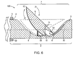
- FIG. 6 is an illustrative cutaway schematic of the first tube at the distal cutting end of the apparatus shown in FIG. 1 including a second tube advanced distally from the first lumen of the first tube according to an illustrative embodiment of the invention.
- FIG. 7 is a cutaway schematic of the first tube at the distal cutting end of the apparatus shown in FIG. 1 including the lever arm in a cutting position and a severed suture according to an illustrative embodiment of the invention.
- FIG. 8 is a cutaway schematic of the first tube at the distal cutting end of the apparatus shown in FIG. 1 including a return guide in an open position according to an illustrative embodiment of the invention.
- FIG. 9 is a cutaway schematic of the first tube at the distal cutting end of the apparatus shown in FIG. 1 including a return guide in a collapsed position according to an illustrative embodiment of the invention.
- FIG. 10 is a perspective schematic of the apparatus of FIG. 1 including a septal occluder with the distal cutting end of the apparatus positioned in the right atrium of the heart according to an illustrative embodiment of the invention.
- the present invention pertains to an apparatus for cutting a suture.
- the apparatus may be used to deliver implants, e.g., intracardiac occluders, for example, intracardiac septal occluders manufactured by NMT Medical Inc., Boston, Mass.
- Intracardiac occluders are used to repair congenital or acquired defects in the heart or the major blood vessels, thereof, including interatrial septal shunts, such as a patent foramen ovale, interventricular septal shunts, patent ductus arteriosus and aortic-pulmonary window.
- FIG. 1 is an illustrative schematic of the apparatus 100 with a cutaway schematic of the first tube according to an illustrative embodiment of the invention.
- the invention relates to an apparatus for remotely severing a suture.
- the exemplary apparatus 100 for cutting a suture includes a proximal control end 1 and a distal cutting end 2 .
- the proximal control end 1 is the end proximal to the operator and used to control the distal cutting end 2 .
- the apparatus 100 also includes a first tube 3 , a second tube 5 , a lever arm 8 , a cutting edge 13 , and a pivot 10 .
- the distal cutting end further includes a return guide (not shown) and/or a spring mechanism (not shown).
- the distal cutting end 2 of the apparatus 100 for remotely cutting a suture includes a portion of the first tube 3 including a first lumen 4 .
- a second tube 5 is longitudinally disposed within the first lumen 4 of the first tube 3 .
- the second tube 5 includes a longitudinally disposed lumen 6 extending from the proximal control end 1 of the apparatus 100 to the distal cutting end 2 of the apparatus 100 .
- the second tube 5 is slidably moveable within the first lumen 4 of the first tube 3 .
- the first tube 3 is generally elongated and has an external diameter sufficiently sized, e.g., a diameter 0.03 mm and a length approximately 150 cm, to allow the first tube 3 to be delivered percutaneously via a vessel to an anatomical site, for example, the atrial septum, in a patient.
- the first lumen 4 is hollow, typically cylindrically shaped, and has an internal diameter slightly larger than the external diameter of the second tube 5 to allow the second tube 5 to slide within the first lumen 4 .
- the second tube 5 is elongated and has an internal diameter sized to allow the hollow and cylindrical second lumen 6 to pass a suture, for example, single 0 catgut, polyethylene or nylon suture.
- the second tube 5 also contains a slot 7 sized and shaped to receive the lever arm 8 pivotably attached to the second tube 5 .
- the first tube 3 is longitudinally and slidably disposed within a catheter 18 .
- the first tube 3 serves as the catheter 18 .
- Materials for construction of the apparatus include but are not limited to polyethylene block copolymer (Pebax®), polytetrafluoroethylene (PTFE), metals such as stainless steel, a ceramic, or a composite material.
- FIG. 2 is a perspective schematic of the second tube 5 at the distal cutting end 2 of the apparatus 100 including the slot 7 and the lever arm 8 according to an illustrative embodiment of the invention.
- the illustrative second tube 5 is a cylindrical tube including a central longitudinal axis 30 .
- the second tube 5 includes two planes, plane 31 and plane 32 , perpendicularly intersecting the central longitudinal axis 30 and perpendicular to each other.
- the slot 7 is a longitudinal defect in the wall 33 of the second tube 5 .
- the slot 7 extends through the entire thickness of the wall 33 to the second lumen 6 .
- the slot 7 is substantially symmetrical about the plane 31 which longitudinally bisects the slot 7 .
- the length 35 of the slot 7 is in the range of about 0.5 mm to 10 mm, or 1 mm to 3 mm, preferably.
- the maximum width 36 of the slot 7 is generally equivalent to the external diameter of the second tube.
- the slot 7 is sized and shaped to receive the lever arm 8 .
- the illustrative lever arm 8 is generally an inverted U shape in a traverse section, wedge-shaped when viewed from the side, and substantially symmetrical about plane 31 .
- the lever arm 8 pivots about a pivot 10 .
- the axis 34 of the pivot 10 is perpendicular to the axis 30 and parallel to the plane 32 .
- the top 40 of the wedge-shaped illustrative lever arm 8 in a collapsed position is parallel to the longitudinal axis 30 of the second tube 5 and is flush with the outer wall 33 of the second tube 5 .
- FIG. 3 is an illustrative schematic of the apparatus 100 including a cutaway of the first tube 3 at the distal cutting end 2 to illustrate the lever arm 8 with a cutting edge 13 shown in FIG. 1 according to one illustrative embodiment of the invention.
- the lever arm 8 pivots about the pivot 10 .
- the top 40 of the wedge-shaped illustrative lever arm 8 is positioned parallel to the longitudinal axis 30 of the second tube 5 and is flush with the outer wall 33 of the second tube 5 .
- the lever arm 8 includes the pivot 10 , a lever arm proximal end 12 , and a lever arm distal end 9 .
- a cutting edge 13 is positioned on the top 40 of the lever arm 8 at the lever arm distal end 9 of the lever arm 8 .
- the cutting edge 13 is a straight edge blade.
- the cutting edge 13 is tooth-like or pointed such that the cutting edge 13 may pierce and/or fracture a suture.
- FIG. 4 is an illustrative schematic of the apparatus 100 including a cutaway of the first tube 3 at the distal cutting end 2 to illustrate the lever arm 8 with a cutting edge 13 ′ shown in FIG. 1 according to another illustrative embodiment of the invention.
- the illustrative cutting edge 13 ′ biases downward in the direction of the pivot 10 at an angle 11 of about 0 to 90 degrees, preferably about 45 degrees from a line perpendicular to the longitudinal axis of the second tube 5 .
- the lever arm 8 includes a pivot 10 according to one illustrative embodiment of the invention.
- the illustrative pivot 10 pivotably connects the lever arm 8 to the second tube 5 .
- the pivot 10 with two ends 41 , 41 ′ is a transverse rod that passes through a solid portion of the second tube 5 connecting the pivot ends 41 , 41 ′ of the lever arm 8 to the second tube 5 .
- the pivot 10 may be located anywhere along the longitudinal axis of the lever arm 8 between the lever arm proximal end 12 and the lever arm distal end 9 , preferably located approximately halfway between the lever arm proximal end 12 and the lever arm distal end 9 .
- FIG. 5 is an illustrative schematic of the lever arm 8 including a pivot 10 ′ according to another illustrative embodiment of the invention.
- the illustrative pivot 10 ′ pivotably connects the lever arm 8 to the second tube 5 .
- the pivot 10 ′ is a flexible material connecting the pivot ends 41 , 41 ′ of the lever arm 8 to the second tube 5 allowing the lever arm 8 to pivot by flexing the flexible material of the pivot 10 ′.
- FIG. 6 is an illustrative cutaway schematic of the first tube 3 at the distal cutting end 2 of the apparatus 100 including either a second tube 5 advanced distally from the first lumen 4 of the first tube 3 or alternatively the first tube 3 and first lumen 4 retracted proximally from the second tube 5 according to an illustrative embodiment of the invention.
- the illustrative slot 7 and the lever arm 8 are extended beyond the distal end 20 of the first tube 3 .
- the slot 7 is sized and shaped to allow the cutting edge 13 to pivot as indicated by arrow 21 into the second lumen 6 of the second tube 5 .
- a biasing mechanism urges the lever arm distal end 9 of the lever arm 8 to move from a collapsed position, shown in phantom, to an open position across the longitudinal axis 30 of the second lumen 6 .
- the desired angle 11 of the lever arm 8 relative to a vertical axis perpendicular to the longitudinal axis 30 of the device 100 is in the range of about 0 degrees to about 90 degrees, preferably 45 degrees. As the lever arm 8 pivots on the pivot 10 , the lever arm proximal end 12 lifts out of the second lumen 6 .
- FIG. 7 is a schematic of the first tube 3 at the distal cutting end 2 of the apparatus 100 including the lever arm 8 in a cutting position extended distally beyond the distal end 20 of the first tube 3 , and a severed suture 14 cut by the cutting edge 13 of the lever arm 8 according to an illustrative embodiment of the invention.
- the illustrative cutting edge 13 cuts the suture 14 into two separate segments.
- FIG. 8 is a cutaway schematic of the first tube 3 at the distal cutting end 2 of the apparatus 100 including a return guide 15 in an open position with the lever arm 8 in a cutting position extended distally beyond the distal end 20 of the first tube 3 according to an illustrative embodiment of the invention.
- the return guide 15 is a wire loop as illustrated in FIG. 9 .
- the wire loop 15 includes two ends 50 , 51 joined to the proximal end 12 of the lever arm 8 and an apex 52 that extends proximally from the two loop ends 50 , 51 .
- the wire loop 15 includes a bend 53 .
- the proximal end 12 of the lever arm 8 returns to a collapsed position enclosed within the slot 7 .
- FIG. 9 is a schematic of the first tube 3 at the distal cutting end 2 of the apparatus 100 including a return guide 15 in the collapsed position according to an illustrative embodiment of the invention.
- the invention is a method for introducing an implant, such as a septal defect occluder, to an anatomical site in a patient.
- an implant such as a septal defect occluder
- the invention is a method for implanting a septal occluder to occlude a patent foramen ovale.
- FIG. 10 is an illustrative schematic of the apparatus 100 including a septal occluder 17 .
- the distal cutting end 2 of the apparatus 100 is positioned in the right atrium 54 of the heart according to an illustrative embodiment of the invention.
- the proximal control end 1 is used by an operator to guide the occluder 17 into position at the patent foramen ovale. Once the occluder 17 is positioned as desired, the operator manipulates the control end 1 to urge the second tube 5 distally, or, alternatively, the first tube 3 proximally until the slot 7 and lever arm 8 are extended beyond the distal end 20 of the first tube 3 .
- the cutting edge 13 of the lever arm distal end 9 engages the suture 14 .
- proximal retraction of the suture 14 draws the suture 14 against the cutting edge 13 thereby severing the suture 14 .
- further distal advancement of the second tube 5 or, alternatively, withdrawal of the first tube 3 proximally advances the cutting edge 13 through the suture 14 , thereby slicing the suture 14 into two segments and releasing the occluder 17 .
- engagement of the cutting edge 13 ′ with the suture 14 fractures the suture 14 such that it may be segmented with minimal tension applied to the suture 14 by the operator.
- the short end of the suture 14 is unthreaded from the occluder 17 and drawn through the catheter 18 towards the proximal control end 1 .
- the short length of the segmented suture 14 that extends from the distal cutting end 2 to the occluder 17 is drawn through the occluder 17 .
Abstract
Description
Claims (21)
Priority Applications (1)
| Application Number | Priority Date | Filing Date | Title |
|---|---|---|---|
| US10/862,939 US7473260B2 (en) | 2003-09-11 | 2004-06-08 | Suture sever tube |
Applications Claiming Priority (2)
| Application Number | Priority Date | Filing Date | Title |
|---|---|---|---|
| US50194903P | 2003-09-11 | 2003-09-11 | |
| US10/862,939 US7473260B2 (en) | 2003-09-11 | 2004-06-08 | Suture sever tube |
Publications (2)
| Publication Number | Publication Date |
|---|---|
| US20050059983A1 US20050059983A1 (en) | 2005-03-17 |
| US7473260B2 true US7473260B2 (en) | 2009-01-06 |
Family
ID=34434835
Family Applications (1)
| Application Number | Title | Priority Date | Filing Date |
|---|---|---|---|
| US10/862,939 Active 2026-03-21 US7473260B2 (en) | 2003-09-11 | 2004-06-08 | Suture sever tube |
Country Status (7)
| Country | Link |
|---|---|
| US (1) | US7473260B2 (en) |
| EP (1) | EP1663014B1 (en) |
| JP (1) | JP2007504886A (en) |
| AT (1) | ATE404126T1 (en) |
| CA (1) | CA2538707A1 (en) |
| DE (1) | DE602004015807D1 (en) |
| WO (1) | WO2005034767A1 (en) |
Cited By (13)
| Publication number | Priority date | Publication date | Assignee | Title |
|---|---|---|---|---|
| US20080147097A1 (en) * | 2003-10-09 | 2008-06-19 | Sentreheart, Inc. | Apparatus and method for the ligation of tissue |
| US20080243183A1 (en) * | 2007-03-30 | 2008-10-02 | Miller Gary H | Devices, systems, and methods for closing the left atrial appendage |
| US20110087247A1 (en) * | 2009-04-01 | 2011-04-14 | Fung Gregory W | Tissue ligation devices and controls therefor |
| US8721663B2 (en) | 1999-05-20 | 2014-05-13 | Sentreheart, Inc. | Methods and apparatus for transpericardial left atrial appendage closure |
| US20140276973A1 (en) * | 2013-03-12 | 2014-09-18 | St. Jude Medical Puerto Rico Llc | Non-invasive suture cutter and related methods for cutting a suture below the skin |
| US9408608B2 (en) | 2013-03-12 | 2016-08-09 | Sentreheart, Inc. | Tissue ligation devices and methods therefor |
| US9486281B2 (en) | 2010-04-13 | 2016-11-08 | Sentreheart, Inc. | Methods and devices for accessing and delivering devices to a heart |
| US9498206B2 (en) | 2011-06-08 | 2016-11-22 | Sentreheart, Inc. | Tissue ligation devices and tensioning devices therefor |
| US9522006B2 (en) | 2005-04-07 | 2016-12-20 | Sentreheart, Inc. | Apparatus and method for the ligation of tissue |
| US9936956B2 (en) | 2015-03-24 | 2018-04-10 | Sentreheart, Inc. | Devices and methods for left atrial appendage closure |
| US10130369B2 (en) | 2015-03-24 | 2018-11-20 | Sentreheart, Inc. | Tissue ligation devices and methods therefor |
| US10258408B2 (en) | 2013-10-31 | 2019-04-16 | Sentreheart, Inc. | Devices and methods for left atrial appendage closure |
| US10292710B2 (en) | 2016-02-26 | 2019-05-21 | Sentreheart, Inc. | Devices and methods for left atrial appendage closure |
Families Citing this family (15)
| Publication number | Priority date | Publication date | Assignee | Title |
|---|---|---|---|---|
| US7338514B2 (en) | 2001-06-01 | 2008-03-04 | St. Jude Medical, Cardiology Division, Inc. | Closure devices, related delivery methods and tools, and related methods of use |
| US7976564B2 (en) * | 2002-05-06 | 2011-07-12 | St. Jude Medical, Cardiology Division, Inc. | PFO closure devices and related methods of use |
| US20040267306A1 (en) * | 2003-04-11 | 2004-12-30 | Velocimed, L.L.C. | Closure devices, related delivery methods, and related methods of use |
| US8372112B2 (en) * | 2003-04-11 | 2013-02-12 | St. Jude Medical, Cardiology Division, Inc. | Closure devices, related delivery methods, and related methods of use |
| US7520886B2 (en) | 2005-01-27 | 2009-04-21 | Wilson-Cook Medical Inc. | Endoscopic cutting device |
| DE602006003120D1 (en) * | 2005-04-26 | 2008-11-27 | Niti On Co Ltd | Endoscopic surgical instrument |
| US7824397B2 (en) | 2005-08-19 | 2010-11-02 | Boston Scientific Scimed, Inc. | Occlusion apparatus |
| US7837619B2 (en) * | 2005-08-19 | 2010-11-23 | Boston Scientific Scimed, Inc. | Transeptal apparatus, system, and method |
| US8062309B2 (en) * | 2005-08-19 | 2011-11-22 | Boston Scientific Scimed, Inc. | Defect occlusion apparatus, system, and method |
| US7998095B2 (en) * | 2005-08-19 | 2011-08-16 | Boston Scientific Scimed, Inc. | Occlusion device |
| US7766906B2 (en) * | 2005-08-19 | 2010-08-03 | Boston Scientific Scimed, Inc. | Occlusion apparatus |
| ES2628732T3 (en) | 2007-09-20 | 2017-08-03 | Sentreheart, Inc. | Devices and methods for remote suture management. |
| EP2415404B1 (en) * | 2010-08-06 | 2017-08-30 | Tornier, Inc. | Arthroscopic device for cutting a suture and arthroscopic surgical kit including such a device |
| EP3035862B1 (en) * | 2013-08-22 | 2020-05-27 | Anchor Orthopedics XT Inc. | Suture cutter |
| CN107307895B (en) * | 2017-07-07 | 2019-12-06 | 河北医科大学第一医院 | Tool for forming wound surface on edge of patent foramen ovale |
Citations (107)
| Publication number | Priority date | Publication date | Assignee | Title |
|---|---|---|---|---|
| US3683892A (en) | 1970-07-13 | 1972-08-15 | Battelle Development Corp | Device for the extraction of core samples |
| US3874388A (en) | 1973-02-12 | 1975-04-01 | Ochsner Med Found Alton | Shunt defect closure system |
| US3990144A (en) | 1975-06-30 | 1976-11-09 | Boris Schwartz | Suture cutter and removal means |
| US4007743A (en) | 1975-10-20 | 1977-02-15 | American Hospital Supply Corporation | Opening mechanism for umbrella-like intravascular shunt defect closure device |
| US4038988A (en) | 1975-12-31 | 1977-08-02 | Pierre Perisse | Surgical apparatus |
| US4069825A (en) | 1976-01-28 | 1978-01-24 | Taichiro Akiyama | Surgical thread and cutting apparatus for the same |
| US4246698A (en) | 1979-07-20 | 1981-01-27 | Laschal Instruments Corp. | Suture remover |
| US4271838A (en) | 1978-04-05 | 1981-06-09 | Laschal Instruments Corp. | Suture cutter |
| US4384406A (en) | 1981-03-05 | 1983-05-24 | Cordis Corporation | Combination suture cutter and remover |
| US4452246A (en) | 1981-09-21 | 1984-06-05 | Bader Robert F | Surgical instrument |
| US4494542A (en) | 1982-03-31 | 1985-01-22 | Lee Mary K | Suture cutter, extractor and method to cut and remove sutures |
| US4799483A (en) | 1988-02-11 | 1989-01-24 | Kraff Manus C | Suturing needle with tail mounted cutting blade and method for using same |
| US4836204A (en) | 1987-07-06 | 1989-06-06 | Landymore Roderick W | Method for effecting closure of a perforation in the septum of the heart |
| US4932963A (en) | 1989-03-02 | 1990-06-12 | United States Surgical Corporation | Combined surgical needle-suture device possessing an integrated suture cut-off feature |
| US4963147A (en) * | 1987-09-18 | 1990-10-16 | John M. Agee | Surgical instrument |
| US4984941A (en) | 1989-03-02 | 1991-01-15 | United States Surgical Corporation | Apparatus for forming a suture cut-off feature in a surgical needle possessing a suture-receiving socket |
| US4986825A (en) * | 1988-10-11 | 1991-01-22 | Concept, Inc. | Surgical cutting instrument |
| US5108420A (en) | 1991-02-01 | 1992-04-28 | Temple University | Aperture occlusion device |
| US5122152A (en) | 1989-02-24 | 1992-06-16 | Mull John D | Suture removing device |
| US5192301A (en) | 1989-01-17 | 1993-03-09 | Nippon Zeon Co., Ltd. | Closing plug of a defect for medical use and a closing plug device utilizing it |
| US5242459A (en) | 1992-07-10 | 1993-09-07 | Laparomed Corporation | Device and method for applying a ligating loop |
| US5284488A (en) | 1992-12-23 | 1994-02-08 | Sideris Eleftherios B | Adjustable devices for the occlusion of cardiac defects |
| US5286255A (en) * | 1991-07-29 | 1994-02-15 | Linvatec Corporation | Surgical forceps |
| US5292327A (en) | 1992-10-08 | 1994-03-08 | Dodd Joseph T | Surgical knot pusher |
| US5301684A (en) * | 1993-04-27 | 1994-04-12 | International Electronic Technology Corp. | Biopsy needle |
| US5312341A (en) | 1992-08-14 | 1994-05-17 | Wayne State University | Retaining apparatus and procedure for transseptal catheterization |
| US5318589A (en) * | 1992-04-15 | 1994-06-07 | Microsurge, Inc. | Surgical instrument for endoscopic surgery |
| US5334217A (en) | 1992-01-21 | 1994-08-02 | Regents Of The University Of Minnesota | Septal defect closure device |
| US5346500A (en) | 1993-02-16 | 1994-09-13 | Sood Suchart | Suture cutting scissor apparatus |
| US5376096A (en) * | 1993-12-17 | 1994-12-27 | Vance Products Inc. | Medical instrument for driving a suture needle |
| US5417700A (en) | 1992-03-30 | 1995-05-23 | Thomas D. Egan | Automatic suturing and ligating device |
| US5425744A (en) | 1991-11-05 | 1995-06-20 | C. R. Bard, Inc. | Occluder for repair of cardiac and vascular defects |
| US5433727A (en) | 1994-08-16 | 1995-07-18 | Sideris; Eleftherios B. | Centering buttoned device for the occlusion of large defects for occluding |
| US5443475A (en) * | 1990-11-09 | 1995-08-22 | Arthrotek, Inc. | Surgical instrument |
| US5451235A (en) | 1991-11-05 | 1995-09-19 | C.R. Bard, Inc. | Occluder and method for repair of cardiac and vascular defects |
| US5496331A (en) | 1993-07-28 | 1996-03-05 | Terumo Kabushiki Kaisha | Knot-forming instrument and method of forming knots |
| US5507811A (en) | 1993-11-26 | 1996-04-16 | Nissho Corporation | Prosthetic device for atrial septal defect repair |
| US5620461A (en) | 1989-05-29 | 1997-04-15 | Muijs Van De Moer; Wouter M. | Sealing device |
| US5634936A (en) | 1995-02-06 | 1997-06-03 | Scimed Life Systems, Inc. | Device for closing a septal defect |
| US5683411A (en) | 1994-04-06 | 1997-11-04 | William Cook Europe A/S | Medical article for implantation into the vascular system of a patient |
| US5702421A (en) | 1995-01-11 | 1997-12-30 | Schneidt; Bernhard | Closure device for closing a vascular opening, such as patent ductus arteriosus |
| US5709707A (en) | 1995-10-30 | 1998-01-20 | Children's Medical Center Corporation | Self-centering umbrella-type septal closure device |
| US5725552A (en) | 1994-07-08 | 1998-03-10 | Aga Medical Corporation | Percutaneous catheter directed intravascular occlusion devices |
| US5733294A (en) | 1996-02-28 | 1998-03-31 | B. Braun Medical, Inc. | Self expanding cardiovascular occlusion device, method of using and method of making the same |
| US5741297A (en) | 1996-08-28 | 1998-04-21 | Simon; Morris | Daisy occluder and method for septal defect repair |
| US5759188A (en) * | 1996-11-27 | 1998-06-02 | Yoon; Inbae | Suturing instrument with rotatably mounted needle driver and catcher |
| US5797958A (en) * | 1989-12-05 | 1998-08-25 | Yoon; Inbae | Endoscopic grasping instrument with scissors |
| US5797939A (en) * | 1989-12-05 | 1998-08-25 | Yoon; Inbae | Endoscopic scissors with longitudinal operating channel |
| US5797907A (en) | 1989-11-06 | 1998-08-25 | Mectra Labs, Inc. | Electrocautery cutter |
| US5800516A (en) | 1996-08-08 | 1998-09-01 | Cordis Corporation | Deployable and retrievable shape memory stent/tube and method |
| US5810884A (en) | 1996-09-09 | 1998-09-22 | Beth Israel Deaconess Medical Center | Apparatus and method for closing a vascular perforation after percutaneous puncture of a blood vessel in a living subject |
| US5853422A (en) | 1996-03-22 | 1998-12-29 | Scimed Life Systems, Inc. | Apparatus and method for closing a septal defect |
| US5860993A (en) | 1996-09-25 | 1999-01-19 | Medworks Corp. | Suture cutter |
| US5861003A (en) | 1996-10-23 | 1999-01-19 | The Cleveland Clinic Foundation | Apparatus and method for occluding a defect or aperture within body surface |
| US5879366A (en) | 1996-12-20 | 1999-03-09 | W.L. Gore & Associates, Inc. | Self-expanding defect closure device and method of making and using |
| US5893863A (en) * | 1989-12-05 | 1999-04-13 | Yoon; Inbae | Surgical instrument with jaws and movable internal hook member for use thereof |
| US5904703A (en) | 1996-05-08 | 1999-05-18 | Bard Connaught | Occluder device formed from an open cell foam material |
| US5908429A (en) * | 1997-05-01 | 1999-06-01 | Yoon; Inbae | Methods of anatomical tissue ligation |
| US5919200A (en) | 1998-10-09 | 1999-07-06 | Hearten Medical, Inc. | Balloon catheter for abrading a patent foramen ovale and method of using the balloon catheter |
| US5928250A (en) | 1997-01-30 | 1999-07-27 | Nissho Corporation | Catheter assembly for intracardiac suture |
| US5944738A (en) | 1998-02-06 | 1999-08-31 | Aga Medical Corporation | Percutaneous catheter directed constricting occlusion device |
| US5976174A (en) | 1997-12-15 | 1999-11-02 | Ruiz; Carlos E. | Medical hole closure device and methods of use |
| US5984939A (en) * | 1989-12-05 | 1999-11-16 | Yoon; Inbae | Multifunctional grasping instrument with cutting member and operating channel for use in endoscopic and non-endoscopic procedures |
| US5993475A (en) | 1998-04-22 | 1999-11-30 | Bristol-Myers Squibb Co. | Tissue repair device |
| US6051004A (en) | 1999-09-20 | 2000-04-18 | Gill; Darrell | Combination needle holder and suture cutter medical instrument |
| US6056760A (en) | 1997-01-30 | 2000-05-02 | Nissho Corporation | Device for intracardiac suture |
| US6063096A (en) | 1997-03-13 | 2000-05-16 | Richard Wolf Gmbh | Needle holder |
| US6077277A (en) * | 1999-04-05 | 2000-06-20 | Starion Instruments, Inc. | Suture welding device |
| US6086606A (en) * | 1998-05-06 | 2000-07-11 | Knodel; Bryan D. | Manually-operable surgical tool suitable for laparoscopic operations, readily adaptable for different functions by quick change of tissue-contacting operational elements |
| US6110127A (en) | 1998-02-17 | 2000-08-29 | Olympus Optical, Co., Ltd. | Medical instrument for use in combination with an endoscope |
| US6113609A (en) | 1998-05-26 | 2000-09-05 | Scimed Life Systems, Inc. | Implantable tissue fastener and system for treating gastroesophageal reflux disease |
| US6171329B1 (en) | 1994-12-19 | 2001-01-09 | Gore Enterprise Holdings, Inc. | Self-expanding defect closure device and method of making and using |
| US6174322B1 (en) | 1997-08-08 | 2001-01-16 | Cardia, Inc. | Occlusion device for the closure of a physical anomaly such as a vascular aperture or an aperture in a septum |
| US6206907B1 (en) | 1999-05-07 | 2001-03-27 | Cardia, Inc. | Occlusion device with stranded wire support arms |
| US6214029B1 (en) | 2000-04-26 | 2001-04-10 | Microvena Corporation | Septal defect occluder |
| US6221092B1 (en) | 1998-03-30 | 2001-04-24 | Nissho Corporation | Closure device for transcatheter operations and catheter assembly therefor |
| US6290674B1 (en) | 1999-09-20 | 2001-09-18 | Appriva Medical, Inc. | Method and apparatus for closing intracardiac septal defects |
| US6322548B1 (en) | 1995-05-10 | 2001-11-27 | Eclipse Surgical Technologies | Delivery catheter system for heart chamber |
| US20020010481A1 (en) | 1999-12-23 | 2002-01-24 | Swaminathan Jayaraman | Occlusive coil manufacture and delivery |
| US20020019648A1 (en) | 2000-04-19 | 2002-02-14 | Dan Akerfeldt | Intra-arterial occluder |
| US20020026208A1 (en) | 2000-01-05 | 2002-02-28 | Medical Technology Group, Inc. | Apparatus and methods for delivering a closure device |
| US6355052B1 (en) | 1996-02-09 | 2002-03-12 | Pfm Produkte Fur Die Medizin Aktiengesellschaft | Device for closure of body defect openings |
| US6375671B1 (en) | 1999-04-19 | 2002-04-23 | Nipro Corporation | Closure device for transcatheter operations |
| US6379368B1 (en) | 1999-05-13 | 2002-04-30 | Cardia, Inc. | Occlusion device with non-thrombogenic properties |
| US20020052572A1 (en) | 2000-09-25 | 2002-05-02 | Kenneth Franco | Resorbable anastomosis stents and plugs and their use in patients |
| US6387104B1 (en) | 1999-11-12 | 2002-05-14 | Scimed Life Systems, Inc. | Method and apparatus for endoscopic repair of the lower esophageal sphincter |
| US6402772B1 (en) | 2000-05-17 | 2002-06-11 | Aga Medical Corporation | Alignment member for delivering a non-symmetrical device with a predefined orientation |
| US20020077555A1 (en) | 2000-12-18 | 2002-06-20 | Yitzhack Schwartz | Method for anchoring a medical device between tissue |
| US20020087178A1 (en) | 2000-08-25 | 2002-07-04 | Nobles Anthony A. | Suture cutter |
| US20020096183A1 (en) | 1993-02-22 | 2002-07-25 | Stevens John H. | Method and apparatus for thoracoscopic intracardiac procedures |
| US20020107531A1 (en) | 2001-02-06 | 2002-08-08 | Schreck Stefan G. | Method and system for tissue repair using dual catheters |
| US6440152B1 (en) | 2000-07-28 | 2002-08-27 | Microvena Corporation | Defect occluder release assembly and method |
| US6482224B1 (en) | 1996-08-22 | 2002-11-19 | The Trustees Of Columbia University In The City Of New York | Endovascular flexible stapling device |
| US20020183787A1 (en) | 2001-06-01 | 2002-12-05 | Velocimed, L.L.C. | Closure devices, related delivery methods and tools, and related methods of use |
| US20020183786A1 (en) | 2001-05-30 | 2002-12-05 | Timothy Girton | Implantable obstruction device for septal defects |
| US6494888B1 (en) | 1999-06-22 | 2002-12-17 | Ndo Surgical, Inc. | Tissue reconfiguration |
| US20030009195A1 (en) | 1999-08-03 | 2003-01-09 | Field Frederic P. | Surgical suturing instrument and method of use |
| US20030028213A1 (en) | 2001-08-01 | 2003-02-06 | Microvena Corporation | Tissue opening occluder |
| US20030045893A1 (en) | 2001-09-06 | 2003-03-06 | Integrated Vascular Systems, Inc. | Clip apparatus for closing septal defects and methods of use |
| US20030050665A1 (en) | 2001-09-07 | 2003-03-13 | Integrated Vascular Systems, Inc. | Needle apparatus for closing septal defects and methods for using such apparatus |
| US20030059640A1 (en) | 1999-11-19 | 2003-03-27 | Denes Marton | High strength vacuum deposited nitinol alloy films and method of making same |
| US6551344B2 (en) | 2000-04-26 | 2003-04-22 | Ev3 Inc. | Septal defect occluder |
| US20030100920A1 (en) | 1999-07-28 | 2003-05-29 | Akin Jodi J. | Devices and methods for interconnecting conduits and closing openings in tissue |
| US20030109891A1 (en) | 2001-12-07 | 2003-06-12 | Mike Dana | Snared suture trimmer |
| US20030120287A1 (en) | 2001-12-21 | 2003-06-26 | Gross T. Daniel | Suture trimmer |
| US6596013B2 (en) | 2001-09-20 | 2003-07-22 | Scimed Life Systems, Inc. | Method and apparatus for treating septal defects |
| US20030139819A1 (en) | 2002-01-18 | 2003-07-24 | Beer Nicholas De | Method and apparatus for closing septal defects |
Family Cites Families (5)
| Publication number | Priority date | Publication date | Assignee | Title |
|---|---|---|---|---|
| US651004A (en) * | 1899-12-23 | 1900-06-05 | Francis Tiffany Bowles | Water-tight bulkhead-door. |
| DE9214580U1 (en) * | 1992-10-28 | 1994-03-03 | Scarfi Andrea | Surgical thread cutter, especially for minimally invasive therapy |
| DE4314463A1 (en) * | 1993-05-03 | 1994-11-10 | Stefan Koscher | Needle holder |
| US7918867B2 (en) * | 2001-12-07 | 2011-04-05 | Abbott Laboratories | Suture trimmer |
| US7094246B2 (en) * | 2001-12-07 | 2006-08-22 | Abbott Laboratories | Suture trimmer |
-
2004
- 2004-06-08 WO PCT/US2004/018119 patent/WO2005034767A1/en active Application Filing
- 2004-06-08 DE DE602004015807T patent/DE602004015807D1/en not_active Expired - Fee Related
- 2004-06-08 AT AT04754671T patent/ATE404126T1/en not_active IP Right Cessation
- 2004-06-08 CA CA002538707A patent/CA2538707A1/en not_active Abandoned
- 2004-06-08 EP EP04754671A patent/EP1663014B1/en not_active Not-in-force
- 2004-06-08 JP JP2006526061A patent/JP2007504886A/en not_active Withdrawn
- 2004-06-08 US US10/862,939 patent/US7473260B2/en active Active
Patent Citations (115)
| Publication number | Priority date | Publication date | Assignee | Title |
|---|---|---|---|---|
| US3683892A (en) | 1970-07-13 | 1972-08-15 | Battelle Development Corp | Device for the extraction of core samples |
| US3874388A (en) | 1973-02-12 | 1975-04-01 | Ochsner Med Found Alton | Shunt defect closure system |
| US3990144A (en) | 1975-06-30 | 1976-11-09 | Boris Schwartz | Suture cutter and removal means |
| US4007743A (en) | 1975-10-20 | 1977-02-15 | American Hospital Supply Corporation | Opening mechanism for umbrella-like intravascular shunt defect closure device |
| US4038988A (en) | 1975-12-31 | 1977-08-02 | Pierre Perisse | Surgical apparatus |
| US4069825A (en) | 1976-01-28 | 1978-01-24 | Taichiro Akiyama | Surgical thread and cutting apparatus for the same |
| US4271838A (en) | 1978-04-05 | 1981-06-09 | Laschal Instruments Corp. | Suture cutter |
| US4246698A (en) | 1979-07-20 | 1981-01-27 | Laschal Instruments Corp. | Suture remover |
| US4384406A (en) | 1981-03-05 | 1983-05-24 | Cordis Corporation | Combination suture cutter and remover |
| US4452246A (en) | 1981-09-21 | 1984-06-05 | Bader Robert F | Surgical instrument |
| US4494542A (en) | 1982-03-31 | 1985-01-22 | Lee Mary K | Suture cutter, extractor and method to cut and remove sutures |
| US4836204A (en) | 1987-07-06 | 1989-06-06 | Landymore Roderick W | Method for effecting closure of a perforation in the septum of the heart |
| US4963147A (en) * | 1987-09-18 | 1990-10-16 | John M. Agee | Surgical instrument |
| US4799483A (en) | 1988-02-11 | 1989-01-24 | Kraff Manus C | Suturing needle with tail mounted cutting blade and method for using same |
| US4986825A (en) * | 1988-10-11 | 1991-01-22 | Concept, Inc. | Surgical cutting instrument |
| US5192301A (en) | 1989-01-17 | 1993-03-09 | Nippon Zeon Co., Ltd. | Closing plug of a defect for medical use and a closing plug device utilizing it |
| US5122152A (en) | 1989-02-24 | 1992-06-16 | Mull John D | Suture removing device |
| US4984941A (en) | 1989-03-02 | 1991-01-15 | United States Surgical Corporation | Apparatus for forming a suture cut-off feature in a surgical needle possessing a suture-receiving socket |
| US4932963A (en) | 1989-03-02 | 1990-06-12 | United States Surgical Corporation | Combined surgical needle-suture device possessing an integrated suture cut-off feature |
| US5620461A (en) | 1989-05-29 | 1997-04-15 | Muijs Van De Moer; Wouter M. | Sealing device |
| US5797907A (en) | 1989-11-06 | 1998-08-25 | Mectra Labs, Inc. | Electrocautery cutter |
| US5893863A (en) * | 1989-12-05 | 1999-04-13 | Yoon; Inbae | Surgical instrument with jaws and movable internal hook member for use thereof |
| US5797958A (en) * | 1989-12-05 | 1998-08-25 | Yoon; Inbae | Endoscopic grasping instrument with scissors |
| US5797939A (en) * | 1989-12-05 | 1998-08-25 | Yoon; Inbae | Endoscopic scissors with longitudinal operating channel |
| US5984939A (en) * | 1989-12-05 | 1999-11-16 | Yoon; Inbae | Multifunctional grasping instrument with cutting member and operating channel for use in endoscopic and non-endoscopic procedures |
| US5649947A (en) * | 1990-11-09 | 1997-07-22 | Arthrotek, Inc. | Surgical instrument |
| US5443475A (en) * | 1990-11-09 | 1995-08-22 | Arthrotek, Inc. | Surgical instrument |
| US5108420A (en) | 1991-02-01 | 1992-04-28 | Temple University | Aperture occlusion device |
| US5286255A (en) * | 1991-07-29 | 1994-02-15 | Linvatec Corporation | Surgical forceps |
| US5425744A (en) | 1991-11-05 | 1995-06-20 | C. R. Bard, Inc. | Occluder for repair of cardiac and vascular defects |
| US5451235A (en) | 1991-11-05 | 1995-09-19 | C.R. Bard, Inc. | Occluder and method for repair of cardiac and vascular defects |
| US6077291A (en) | 1992-01-21 | 2000-06-20 | Regents Of The University Of Minnesota | Septal defect closure device |
| US5334217A (en) | 1992-01-21 | 1994-08-02 | Regents Of The University Of Minnesota | Septal defect closure device |
| US5417700A (en) | 1992-03-30 | 1995-05-23 | Thomas D. Egan | Automatic suturing and ligating device |
| US5318589A (en) * | 1992-04-15 | 1994-06-07 | Microsurge, Inc. | Surgical instrument for endoscopic surgery |
| US5242459A (en) | 1992-07-10 | 1993-09-07 | Laparomed Corporation | Device and method for applying a ligating loop |
| US5312341A (en) | 1992-08-14 | 1994-05-17 | Wayne State University | Retaining apparatus and procedure for transseptal catheterization |
| US5292327A (en) | 1992-10-08 | 1994-03-08 | Dodd Joseph T | Surgical knot pusher |
| US5284488A (en) | 1992-12-23 | 1994-02-08 | Sideris Eleftherios B | Adjustable devices for the occlusion of cardiac defects |
| US5346500A (en) | 1993-02-16 | 1994-09-13 | Sood Suchart | Suture cutting scissor apparatus |
| US20020096183A1 (en) | 1993-02-22 | 2002-07-25 | Stevens John H. | Method and apparatus for thoracoscopic intracardiac procedures |
| US5301684A (en) * | 1993-04-27 | 1994-04-12 | International Electronic Technology Corp. | Biopsy needle |
| US5496331A (en) | 1993-07-28 | 1996-03-05 | Terumo Kabushiki Kaisha | Knot-forming instrument and method of forming knots |
| US5507811A (en) | 1993-11-26 | 1996-04-16 | Nissho Corporation | Prosthetic device for atrial septal defect repair |
| US5376096A (en) * | 1993-12-17 | 1994-12-27 | Vance Products Inc. | Medical instrument for driving a suture needle |
| US5683411A (en) | 1994-04-06 | 1997-11-04 | William Cook Europe A/S | Medical article for implantation into the vascular system of a patient |
| US5725552A (en) | 1994-07-08 | 1998-03-10 | Aga Medical Corporation | Percutaneous catheter directed intravascular occlusion devices |
| US5433727A (en) | 1994-08-16 | 1995-07-18 | Sideris; Eleftherios B. | Centering buttoned device for the occlusion of large defects for occluding |
| US6171329B1 (en) | 1994-12-19 | 2001-01-09 | Gore Enterprise Holdings, Inc. | Self-expanding defect closure device and method of making and using |
| US5702421A (en) | 1995-01-11 | 1997-12-30 | Schneidt; Bernhard | Closure device for closing a vascular opening, such as patent ductus arteriosus |
| US6270515B1 (en) | 1995-02-06 | 2001-08-07 | Scimed Life Systems, Inc. | Device for closing a septal defect |
| US5634936A (en) | 1995-02-06 | 1997-06-03 | Scimed Life Systems, Inc. | Device for closing a septal defect |
| US6322548B1 (en) | 1995-05-10 | 2001-11-27 | Eclipse Surgical Technologies | Delivery catheter system for heart chamber |
| US5709707A (en) | 1995-10-30 | 1998-01-20 | Children's Medical Center Corporation | Self-centering umbrella-type septal closure device |
| US6355052B1 (en) | 1996-02-09 | 2002-03-12 | Pfm Produkte Fur Die Medizin Aktiengesellschaft | Device for closure of body defect openings |
| US5733294A (en) | 1996-02-28 | 1998-03-31 | B. Braun Medical, Inc. | Self expanding cardiovascular occlusion device, method of using and method of making the same |
| US6312446B1 (en) | 1996-03-22 | 2001-11-06 | Scimed Life Systems, Inc. | Apparatus and method for closing a septal defect |
| US6024756A (en) | 1996-03-22 | 2000-02-15 | Scimed Life Systems, Inc. | Method of reversibly closing a septal defect |
| US5853422A (en) | 1996-03-22 | 1998-12-29 | Scimed Life Systems, Inc. | Apparatus and method for closing a septal defect |
| US6117159A (en) | 1996-03-22 | 2000-09-12 | Scimed Life Systems, Inc. | Apparatus and method for closing a septal defect |
| US5904703A (en) | 1996-05-08 | 1999-05-18 | Bard Connaught | Occluder device formed from an open cell foam material |
| US5800516A (en) | 1996-08-08 | 1998-09-01 | Cordis Corporation | Deployable and retrievable shape memory stent/tube and method |
| US6482224B1 (en) | 1996-08-22 | 2002-11-19 | The Trustees Of Columbia University In The City Of New York | Endovascular flexible stapling device |
| US5741297A (en) | 1996-08-28 | 1998-04-21 | Simon; Morris | Daisy occluder and method for septal defect repair |
| US5810884A (en) | 1996-09-09 | 1998-09-22 | Beth Israel Deaconess Medical Center | Apparatus and method for closing a vascular perforation after percutaneous puncture of a blood vessel in a living subject |
| US5860993A (en) | 1996-09-25 | 1999-01-19 | Medworks Corp. | Suture cutter |
| US5861003A (en) | 1996-10-23 | 1999-01-19 | The Cleveland Clinic Foundation | Apparatus and method for occluding a defect or aperture within body surface |
| US5759188A (en) * | 1996-11-27 | 1998-06-02 | Yoon; Inbae | Suturing instrument with rotatably mounted needle driver and catcher |
| US6623508B2 (en) | 1996-12-20 | 2003-09-23 | Gore Enterprise Holdings, Inc. | Self-expanding defect closure device and method of making and using |
| US6080182A (en) | 1996-12-20 | 2000-06-27 | Gore Enterprise Holdings, Inc. | Self-expanding defect closure device and method of making and using |
| US5879366A (en) | 1996-12-20 | 1999-03-09 | W.L. Gore & Associates, Inc. | Self-expanding defect closure device and method of making and using |
| US6056760A (en) | 1997-01-30 | 2000-05-02 | Nissho Corporation | Device for intracardiac suture |
| US5928250A (en) | 1997-01-30 | 1999-07-27 | Nissho Corporation | Catheter assembly for intracardiac suture |
| US6063096A (en) | 1997-03-13 | 2000-05-16 | Richard Wolf Gmbh | Needle holder |
| US5908429A (en) * | 1997-05-01 | 1999-06-01 | Yoon; Inbae | Methods of anatomical tissue ligation |
| US6174322B1 (en) | 1997-08-08 | 2001-01-16 | Cardia, Inc. | Occlusion device for the closure of a physical anomaly such as a vascular aperture or an aperture in a septum |
| US5976174A (en) | 1997-12-15 | 1999-11-02 | Ruiz; Carlos E. | Medical hole closure device and methods of use |
| US5944738A (en) | 1998-02-06 | 1999-08-31 | Aga Medical Corporation | Percutaneous catheter directed constricting occlusion device |
| US6110127A (en) | 1998-02-17 | 2000-08-29 | Olympus Optical, Co., Ltd. | Medical instrument for use in combination with an endoscope |
| US6221092B1 (en) | 1998-03-30 | 2001-04-24 | Nissho Corporation | Closure device for transcatheter operations and catheter assembly therefor |
| US5993475A (en) | 1998-04-22 | 1999-11-30 | Bristol-Myers Squibb Co. | Tissue repair device |
| US6086606A (en) * | 1998-05-06 | 2000-07-11 | Knodel; Bryan D. | Manually-operable surgical tool suitable for laparoscopic operations, readily adaptable for different functions by quick change of tissue-contacting operational elements |
| US6113609A (en) | 1998-05-26 | 2000-09-05 | Scimed Life Systems, Inc. | Implantable tissue fastener and system for treating gastroesophageal reflux disease |
| US5919200A (en) | 1998-10-09 | 1999-07-06 | Hearten Medical, Inc. | Balloon catheter for abrading a patent foramen ovale and method of using the balloon catheter |
| US6077277A (en) * | 1999-04-05 | 2000-06-20 | Starion Instruments, Inc. | Suture welding device |
| US6375671B1 (en) | 1999-04-19 | 2002-04-23 | Nipro Corporation | Closure device for transcatheter operations |
| US6206907B1 (en) | 1999-05-07 | 2001-03-27 | Cardia, Inc. | Occlusion device with stranded wire support arms |
| US6379368B1 (en) | 1999-05-13 | 2002-04-30 | Cardia, Inc. | Occlusion device with non-thrombogenic properties |
| US6494888B1 (en) | 1999-06-22 | 2002-12-17 | Ndo Surgical, Inc. | Tissue reconfiguration |
| US20030100920A1 (en) | 1999-07-28 | 2003-05-29 | Akin Jodi J. | Devices and methods for interconnecting conduits and closing openings in tissue |
| US20030009195A1 (en) | 1999-08-03 | 2003-01-09 | Field Frederic P. | Surgical suturing instrument and method of use |
| US6290674B1 (en) | 1999-09-20 | 2001-09-18 | Appriva Medical, Inc. | Method and apparatus for closing intracardiac septal defects |
| US6051004A (en) | 1999-09-20 | 2000-04-18 | Gill; Darrell | Combination needle holder and suture cutter medical instrument |
| US6387104B1 (en) | 1999-11-12 | 2002-05-14 | Scimed Life Systems, Inc. | Method and apparatus for endoscopic repair of the lower esophageal sphincter |
| US20030059640A1 (en) | 1999-11-19 | 2003-03-27 | Denes Marton | High strength vacuum deposited nitinol alloy films and method of making same |
| US20020010481A1 (en) | 1999-12-23 | 2002-01-24 | Swaminathan Jayaraman | Occlusive coil manufacture and delivery |
| US20020026208A1 (en) | 2000-01-05 | 2002-02-28 | Medical Technology Group, Inc. | Apparatus and methods for delivering a closure device |
| US20020019648A1 (en) | 2000-04-19 | 2002-02-14 | Dan Akerfeldt | Intra-arterial occluder |
| US6214029B1 (en) | 2000-04-26 | 2001-04-10 | Microvena Corporation | Septal defect occluder |
| US6551344B2 (en) | 2000-04-26 | 2003-04-22 | Ev3 Inc. | Septal defect occluder |
| US6402772B1 (en) | 2000-05-17 | 2002-06-11 | Aga Medical Corporation | Alignment member for delivering a non-symmetrical device with a predefined orientation |
| US6440152B1 (en) | 2000-07-28 | 2002-08-27 | Microvena Corporation | Defect occluder release assembly and method |
| US20020087178A1 (en) | 2000-08-25 | 2002-07-04 | Nobles Anthony A. | Suture cutter |
| US20020052572A1 (en) | 2000-09-25 | 2002-05-02 | Kenneth Franco | Resorbable anastomosis stents and plugs and their use in patients |
| US20020077555A1 (en) | 2000-12-18 | 2002-06-20 | Yitzhack Schwartz | Method for anchoring a medical device between tissue |
| US20020107531A1 (en) | 2001-02-06 | 2002-08-08 | Schreck Stefan G. | Method and system for tissue repair using dual catheters |
| US20020183786A1 (en) | 2001-05-30 | 2002-12-05 | Timothy Girton | Implantable obstruction device for septal defects |
| US20020183787A1 (en) | 2001-06-01 | 2002-12-05 | Velocimed, L.L.C. | Closure devices, related delivery methods and tools, and related methods of use |
| US20030028213A1 (en) | 2001-08-01 | 2003-02-06 | Microvena Corporation | Tissue opening occluder |
| US20030045893A1 (en) | 2001-09-06 | 2003-03-06 | Integrated Vascular Systems, Inc. | Clip apparatus for closing septal defects and methods of use |
| US20030050665A1 (en) | 2001-09-07 | 2003-03-13 | Integrated Vascular Systems, Inc. | Needle apparatus for closing septal defects and methods for using such apparatus |
| US6596013B2 (en) | 2001-09-20 | 2003-07-22 | Scimed Life Systems, Inc. | Method and apparatus for treating septal defects |
| US20030109891A1 (en) | 2001-12-07 | 2003-06-12 | Mike Dana | Snared suture trimmer |
| US20030120287A1 (en) | 2001-12-21 | 2003-06-26 | Gross T. Daniel | Suture trimmer |
| US20030139819A1 (en) | 2002-01-18 | 2003-07-24 | Beer Nicholas De | Method and apparatus for closing septal defects |
Non-Patent Citations (3)
| Title |
|---|
| International Preliminary Report on Patentability for PCT/US2004/018119, mailed on Mar. 23, 2006 (10 pages). |
| International Search Report for PCT/US04/18119, mailed on Nov. 10, 2004 (5 pages). |
| Written Opinion for PCT/ US04/18119, mailed on Nov. 10, 2004 (8 pages). |
Cited By (40)
| Publication number | Priority date | Publication date | Assignee | Title |
|---|---|---|---|---|
| US8721663B2 (en) | 1999-05-20 | 2014-05-13 | Sentreheart, Inc. | Methods and apparatus for transpericardial left atrial appendage closure |
| US9724105B2 (en) | 1999-05-20 | 2017-08-08 | Sentreheart, Inc. | Methods and apparatus for transpericardial left atrial appendage closure |
| US8974473B2 (en) | 1999-05-20 | 2015-03-10 | Sentreheart, Inc. | Methods and apparatus for transpericardial left atrial appendage closure |
| US9271819B2 (en) | 2003-10-09 | 2016-03-01 | Sentreheart, Inc. | Apparatus and method for the ligation of tissue |
| US20080221593A1 (en) * | 2003-10-09 | 2008-09-11 | Sentreheart, Inc. | Apparatus and method for the ligation of tissue |
| US11350944B2 (en) | 2003-10-09 | 2022-06-07 | Sentreheart Llc | Apparatus and method for the ligation of tissue |
| US10806460B2 (en) | 2003-10-09 | 2020-10-20 | Sentreheart Llc | Apparatus and method for the ligation of tissue |
| US10327780B2 (en) | 2003-10-09 | 2019-06-25 | Sentreheart, Inc. | Apparatus and method for the ligation of tissue |
| US20080147097A1 (en) * | 2003-10-09 | 2008-06-19 | Sentreheart, Inc. | Apparatus and method for the ligation of tissue |
| US8795297B2 (en) | 2003-10-09 | 2014-08-05 | Sentreheart, Inc. | Apparatus and method for the ligation of tissue |
| US9522006B2 (en) | 2005-04-07 | 2016-12-20 | Sentreheart, Inc. | Apparatus and method for the ligation of tissue |
| US11020122B2 (en) | 2007-03-30 | 2021-06-01 | Sentreheart Llc | Methods for closing the left atrial appendage |
| US20080243183A1 (en) * | 2007-03-30 | 2008-10-02 | Miller Gary H | Devices, systems, and methods for closing the left atrial appendage |
| US20090157118A1 (en) * | 2007-03-30 | 2009-06-18 | Sentreheart, Inc. | Devices, systems, and methods for closing the left atrial appendage |
| US9498223B2 (en) | 2007-03-30 | 2016-11-22 | Sentreheart, Inc. | Devices for closing the left atrial appendage |
| US8771297B2 (en) | 2007-03-30 | 2014-07-08 | Sentreheart, Inc. | Devices, systems, and methods for closing the left atrial appendage |
| US11826050B2 (en) | 2007-03-30 | 2023-11-28 | Atricure, Inc. | Devices, systems, and methods for closing the left atrial appendage |
| US10966725B2 (en) | 2007-03-30 | 2021-04-06 | Sentreheart Llc | Devices and systems for closing the left atrial appendage |
| US9198664B2 (en) | 2009-04-01 | 2015-12-01 | Sentreheart, Inc. | Tissue ligation devices and controls therefor |
| US11950784B2 (en) | 2009-04-01 | 2024-04-09 | Atricure, Inc. | Tissue ligation devices and controls therefor |
| US10799241B2 (en) | 2009-04-01 | 2020-10-13 | Sentreheart Llc | Tissue ligation devices and controls therefor |
| US20110087247A1 (en) * | 2009-04-01 | 2011-04-14 | Fung Gregory W | Tissue ligation devices and controls therefor |
| US9486281B2 (en) | 2010-04-13 | 2016-11-08 | Sentreheart, Inc. | Methods and devices for accessing and delivering devices to a heart |
| US10405919B2 (en) | 2010-04-13 | 2019-09-10 | Sentreheart, Inc. | Methods and devices for treating atrial fibrillation |
| US11026690B2 (en) | 2011-06-08 | 2021-06-08 | Sentreheart Llc | Tissue ligation devices and tensioning devices therefor |
| US9498206B2 (en) | 2011-06-08 | 2016-11-22 | Sentreheart, Inc. | Tissue ligation devices and tensioning devices therefor |
| US11207073B2 (en) | 2013-03-12 | 2021-12-28 | Sentreheart Llc | Tissue ligation devices and methods therefor |
| US10251650B2 (en) | 2013-03-12 | 2019-04-09 | Sentreheart, Inc. | Tissue litigation devices and methods therefor |
| US9980719B2 (en) * | 2013-03-12 | 2018-05-29 | St. Jude Medical Puerto Rico Llc | Non-invasive suture cutter and related methods for cutting a suture below the skin |
| US20140276973A1 (en) * | 2013-03-12 | 2014-09-18 | St. Jude Medical Puerto Rico Llc | Non-invasive suture cutter and related methods for cutting a suture below the skin |
| US9408608B2 (en) | 2013-03-12 | 2016-08-09 | Sentreheart, Inc. | Tissue ligation devices and methods therefor |
| US11844566B2 (en) | 2013-10-31 | 2023-12-19 | Atricure, Inc. | Devices and methods for left atrial appendage closure |
| US10799288B2 (en) | 2013-10-31 | 2020-10-13 | Sentreheart Llc | Devices and methods for left atrial appendage closure |
| US10258408B2 (en) | 2013-10-31 | 2019-04-16 | Sentreheart, Inc. | Devices and methods for left atrial appendage closure |
| US10130369B2 (en) | 2015-03-24 | 2018-11-20 | Sentreheart, Inc. | Tissue ligation devices and methods therefor |
| US10959734B2 (en) | 2015-03-24 | 2021-03-30 | Sentreheart Llc | Tissue ligation devices and methods therefor |
| US10716571B2 (en) | 2015-03-24 | 2020-07-21 | Sentreheart Llc | Devices and methods for left atrial appendage closure |
| US9936956B2 (en) | 2015-03-24 | 2018-04-10 | Sentreheart, Inc. | Devices and methods for left atrial appendage closure |
| US11389167B2 (en) | 2016-02-26 | 2022-07-19 | Atricure, Inc. | Devices and methods for left atrial appendage closure |
| US10292710B2 (en) | 2016-02-26 | 2019-05-21 | Sentreheart, Inc. | Devices and methods for left atrial appendage closure |
Also Published As
| Publication number | Publication date |
|---|---|
| EP1663014B1 (en) | 2008-08-13 |
| US20050059983A1 (en) | 2005-03-17 |
| DE602004015807D1 (en) | 2008-09-25 |
| WO2005034767A9 (en) | 2005-05-19 |
| ATE404126T1 (en) | 2008-08-15 |
| CA2538707A1 (en) | 2005-04-21 |
| EP1663014A1 (en) | 2006-06-07 |
| JP2007504886A (en) | 2007-03-08 |
| WO2005034767A1 (en) | 2005-04-21 |
Similar Documents
| Publication | Publication Date | Title |
|---|---|---|
| US7473260B2 (en) | Suture sever tube | |
| US8911457B2 (en) | Method of using knot pusher and suture cutter instrument | |
| EP2059175B1 (en) | Shape memory filament for suture management | |
| US7674275B2 (en) | Suture anchor | |
| US8252005B2 (en) | System, apparatus, and method for fastening tissue | |
| EP2265188B1 (en) | Medical suturing device | |
| US10716561B2 (en) | Implant system | |
| US20080027468A1 (en) | Suture needle, suture needle/suture assembly and suture passer device | |
| US20120283752A1 (en) | Suturing Devices and Methods for Closing a Patent Foramen Ovale | |
| US11779320B2 (en) | Vascular closure device | |
| JP2010500120A (en) | System and method for complete internal suture fixation for implant attachment and soft tissue repair | |
| CN108261227B (en) | Puncture core subassembly and have its puncture ware | |
| WO2008010738A2 (en) | Patent foramen ovale occluder with suture based anchor | |
| WO2000069342A2 (en) | Surgical knot pusher | |
| CN108652711B (en) | Puncture core assembly with sewing function and puncture device thereof | |
| AU2021215258B2 (en) | Multi-barrel drill guide | |
| JP2019122790A (en) | Tissue closure device and method | |
| US20240065838A1 (en) | Systems and methods for minimally invasive annuloplasty | |
| CN112263289B (en) | Clamping device and suturing device | |
| US20230210519A1 (en) | Jointed device for automatic suture and method for same | |
| US9968374B2 (en) | Method and instruments for placement of flexible cannulae | |
| CN117503209A (en) | tissue biopsy device |
Legal Events
| Date | Code | Title | Description |
|---|---|---|---|
| AS | Assignment |
Owner name: NMT MEDICAL, INC., MASSACHUSETTS Free format text: ASSIGNMENT OF ASSIGNORS INTEREST;ASSIGNORS:OPOLSKI, STEVEN;FORDE, SEAN;REEL/FRAME:015677/0445 Effective date: 20040528 |
|
| STCF | Information on status: patent grant |
Free format text: PATENTED CASE |
|
| AS | Assignment |
Owner name: SILICON VALLEY BANK, CALIFORNIA Free format text: SECURITY AGREEMENT;ASSIGNOR:NMT MEDICAL, INC.;REEL/FRAME:022990/0295 Effective date: 20090626 Owner name: SILICON VALLEY BANK,CALIFORNIA Free format text: SECURITY AGREEMENT;ASSIGNOR:NMT MEDICAL, INC.;REEL/FRAME:022990/0295 Effective date: 20090626 |
|
| AS | Assignment |
Owner name: NMT MEDICAL, INC., MASSACHUSETTS Free format text: RELEASE BY SECURED PARTY;ASSIGNOR:SILICON VALLEY BANK;REEL/FRAME:025641/0730 Effective date: 20101215 |
|
| AS | Assignment |
Owner name: W.L. GORE & ASSOCIATES, INC., ARIZONA Free format text: ASSIGNMENT OF ASSIGNORS INTEREST;ASSIGNOR:NMT MEDICAL, INC. (BY AND THROUGH JOSEPH F. FINN, JR., AS ASSIGNEE FOR THE BENEFIT OF CREDITORS OF NMT MEDICAL, INC.);REEL/FRAME:026503/0273 Effective date: 20110616 |
|
| FPAY | Fee payment |
Year of fee payment: 4 |
|
| FEPP | Fee payment procedure |
Free format text: PAT HOLDER NO LONGER CLAIMS SMALL ENTITY STATUS, ENTITY STATUS SET TO UNDISCOUNTED (ORIGINAL EVENT CODE: STOL); ENTITY STATUS OF PATENT OWNER: LARGE ENTITY |
|
| FPAY | Fee payment |
Year of fee payment: 8 |
|
| SULP | Surcharge for late payment | ||
| MAFP | Maintenance fee payment |
Free format text: PAYMENT OF MAINTENANCE FEE, 12TH YEAR, LARGE ENTITY (ORIGINAL EVENT CODE: M1553); ENTITY STATUS OF PATENT OWNER: LARGE ENTITY Year of fee payment: 12 |