US7474099B2 - NMR apparatus with commonly cooled probe head and cryogenic container and method for the operation thereof - Google Patents
NMR apparatus with commonly cooled probe head and cryogenic container and method for the operation thereof Download PDFInfo
- Publication number
- US7474099B2 US7474099B2 US11/509,778 US50977806A US7474099B2 US 7474099 B2 US7474099 B2 US 7474099B2 US 50977806 A US50977806 A US 50977806A US 7474099 B2 US7474099 B2 US 7474099B2
- Authority
- US
- United States
- Prior art keywords
- cryocontainer
- cold
- cooling
- nmr
- refrigerant
- Prior art date
- Legal status (The legal status is an assumption and is not a legal conclusion. Google has not performed a legal analysis and makes no representation as to the accuracy of the status listed.)
- Active, expires
Links
- 239000000523 sample Substances 0.000 title claims abstract description 87
- 238000000034 method Methods 0.000 title claims description 16
- 238000001816 cooling Methods 0.000 claims abstract description 172
- 230000005855 radiation Effects 0.000 claims abstract description 36
- 239000000725 suspension Substances 0.000 claims abstract description 33
- 239000003507 refrigerant Substances 0.000 claims description 74
- IJGRMHOSHXDMSA-UHFFFAOYSA-N Atomic nitrogen Chemical compound N#N IJGRMHOSHXDMSA-UHFFFAOYSA-N 0.000 claims description 34
- 238000012546 transfer Methods 0.000 claims description 26
- 239000007789 gas Substances 0.000 claims description 20
- 239000007788 liquid Substances 0.000 claims description 17
- 229910052757 nitrogen Inorganic materials 0.000 claims description 17
- 239000001307 helium Substances 0.000 claims description 16
- 229910052734 helium Inorganic materials 0.000 claims description 16
- SWQJXJOGLNCZEY-UHFFFAOYSA-N helium atom Chemical compound [He] SWQJXJOGLNCZEY-UHFFFAOYSA-N 0.000 claims description 16
- 238000005057 refrigeration Methods 0.000 claims description 16
- 238000009835 boiling Methods 0.000 claims description 7
- 238000001704 evaporation Methods 0.000 claims description 7
- 238000009413 insulation Methods 0.000 claims description 7
- 238000005485 electric heating Methods 0.000 claims description 4
- 230000005540 biological transmission Effects 0.000 claims description 3
- 238000011835 investigation Methods 0.000 claims description 2
- 238000003780 insertion Methods 0.000 claims 1
- 230000037431 insertion Effects 0.000 claims 1
- 230000000694 effects Effects 0.000 abstract description 5
- 238000010276 construction Methods 0.000 abstract description 3
- 238000005481 NMR spectroscopy Methods 0.000 description 94
- 230000008901 benefit Effects 0.000 description 3
- 230000008878 coupling Effects 0.000 description 3
- 238000010168 coupling process Methods 0.000 description 3
- 238000005859 coupling reaction Methods 0.000 description 3
- 230000007246 mechanism Effects 0.000 description 3
- 238000004886 process control Methods 0.000 description 3
- 238000004435 EPR spectroscopy Methods 0.000 description 2
- 238000012423 maintenance Methods 0.000 description 2
- 238000005259 measurement Methods 0.000 description 2
- 238000009420 retrofitting Methods 0.000 description 2
- 238000004611 spectroscopical analysis Methods 0.000 description 2
- RYGMFSIKBFXOCR-UHFFFAOYSA-N Copper Chemical compound [Cu] RYGMFSIKBFXOCR-UHFFFAOYSA-N 0.000 description 1
- 229910052802 copper Inorganic materials 0.000 description 1
- 239000010949 copper Substances 0.000 description 1
- 238000013461 design Methods 0.000 description 1
- 230000008020 evaporation Effects 0.000 description 1
- 238000010438 heat treatment Methods 0.000 description 1
- 238000003384 imaging method Methods 0.000 description 1
- 239000012535 impurity Substances 0.000 description 1
- 238000009434 installation Methods 0.000 description 1
- 239000000463 material Substances 0.000 description 1
- 238000005457 optimization Methods 0.000 description 1
- 230000008569 process Effects 0.000 description 1
- 230000009467 reduction Effects 0.000 description 1
- 238000010079 rubber tapping Methods 0.000 description 1
- 229920006395 saturated elastomer Polymers 0.000 description 1
- 239000002887 superconductor Substances 0.000 description 1
Images


Classifications
-
- F—MECHANICAL ENGINEERING; LIGHTING; HEATING; WEAPONS; BLASTING
- F25—REFRIGERATION OR COOLING; COMBINED HEATING AND REFRIGERATION SYSTEMS; HEAT PUMP SYSTEMS; MANUFACTURE OR STORAGE OF ICE; LIQUEFACTION SOLIDIFICATION OF GASES
- F25D—REFRIGERATORS; COLD ROOMS; ICE-BOXES; COOLING OR FREEZING APPARATUS NOT OTHERWISE PROVIDED FOR
- F25D19/00—Arrangement or mounting of refrigeration units with respect to devices or objects to be refrigerated, e.g. infrared detectors
- F25D19/006—Thermal coupling structure or interface
-
- G—PHYSICS
- G01—MEASURING; TESTING
- G01R—MEASURING ELECTRIC VARIABLES; MEASURING MAGNETIC VARIABLES
- G01R33/00—Arrangements or instruments for measuring magnetic variables
- G01R33/20—Arrangements or instruments for measuring magnetic variables involving magnetic resonance
- G01R33/28—Details of apparatus provided for in groups G01R33/44 - G01R33/64
- G01R33/30—Sample handling arrangements, e.g. sample cells, spinning mechanisms
- G01R33/31—Temperature control thereof
-
- G—PHYSICS
- G01—MEASURING; TESTING
- G01R—MEASURING ELECTRIC VARIABLES; MEASURING MAGNETIC VARIABLES
- G01R33/00—Arrangements or instruments for measuring magnetic variables
- G01R33/20—Arrangements or instruments for measuring magnetic variables involving magnetic resonance
- G01R33/28—Details of apparatus provided for in groups G01R33/44 - G01R33/64
- G01R33/38—Systems for generation, homogenisation or stabilisation of the main or gradient magnetic field
- G01R33/381—Systems for generation, homogenisation or stabilisation of the main or gradient magnetic field using electromagnets
- G01R33/3815—Systems for generation, homogenisation or stabilisation of the main or gradient magnetic field using electromagnets with superconducting coils, e.g. power supply therefor
-
- F—MECHANICAL ENGINEERING; LIGHTING; HEATING; WEAPONS; BLASTING
- F25—REFRIGERATION OR COOLING; COMBINED HEATING AND REFRIGERATION SYSTEMS; HEAT PUMP SYSTEMS; MANUFACTURE OR STORAGE OF ICE; LIQUEFACTION SOLIDIFICATION OF GASES
- F25B—REFRIGERATION MACHINES, PLANTS OR SYSTEMS; COMBINED HEATING AND REFRIGERATION SYSTEMS; HEAT PUMP SYSTEMS
- F25B2309/00—Gas cycle refrigeration machines
- F25B2309/14—Compression machines, plants or systems characterised by the cycle used
- F25B2309/1418—Pulse-tube cycles with valves in gas supply and return lines
-
- F—MECHANICAL ENGINEERING; LIGHTING; HEATING; WEAPONS; BLASTING
- F25—REFRIGERATION OR COOLING; COMBINED HEATING AND REFRIGERATION SYSTEMS; HEAT PUMP SYSTEMS; MANUFACTURE OR STORAGE OF ICE; LIQUEFACTION SOLIDIFICATION OF GASES
- F25B—REFRIGERATION MACHINES, PLANTS OR SYSTEMS; COMBINED HEATING AND REFRIGERATION SYSTEMS; HEAT PUMP SYSTEMS
- F25B2400/00—General features or devices for refrigeration machines, plants or systems, combined heating and refrigeration systems or heat-pump systems, i.e. not limited to a particular subgroup of F25B
- F25B2400/17—Re-condensers
-
- F—MECHANICAL ENGINEERING; LIGHTING; HEATING; WEAPONS; BLASTING
- F25—REFRIGERATION OR COOLING; COMBINED HEATING AND REFRIGERATION SYSTEMS; HEAT PUMP SYSTEMS; MANUFACTURE OR STORAGE OF ICE; LIQUEFACTION SOLIDIFICATION OF GASES
- F25B—REFRIGERATION MACHINES, PLANTS OR SYSTEMS; COMBINED HEATING AND REFRIGERATION SYSTEMS; HEAT PUMP SYSTEMS
- F25B9/00—Compression machines, plants or systems, in which the refrigerant is air or other gas of low boiling point
- F25B9/10—Compression machines, plants or systems, in which the refrigerant is air or other gas of low boiling point with several cooling stages
-
- F—MECHANICAL ENGINEERING; LIGHTING; HEATING; WEAPONS; BLASTING
- F25—REFRIGERATION OR COOLING; COMBINED HEATING AND REFRIGERATION SYSTEMS; HEAT PUMP SYSTEMS; MANUFACTURE OR STORAGE OF ICE; LIQUEFACTION SOLIDIFICATION OF GASES
- F25B—REFRIGERATION MACHINES, PLANTS OR SYSTEMS; COMBINED HEATING AND REFRIGERATION SYSTEMS; HEAT PUMP SYSTEMS
- F25B9/00—Compression machines, plants or systems, in which the refrigerant is air or other gas of low boiling point
- F25B9/14—Compression machines, plants or systems, in which the refrigerant is air or other gas of low boiling point characterised by the cycle used, e.g. Stirling cycle
- F25B9/145—Compression machines, plants or systems, in which the refrigerant is air or other gas of low boiling point characterised by the cycle used, e.g. Stirling cycle pulse-tube cycle
Definitions
- the invention concerns an NMR apparatus comprising an NMR magnet system disposed in a first cryocontainer of a cryostat, and an NMR probe head disposed in a room temperature bore of the cryostat and comprising an RF resonator for receiving NMR signals from a sample under investigation, and with a preamplifier, wherein the first cryocontainer is installed in an evacuated outer jacket and is surrounded by at least one radiation shield and/or a further cryocontainer, wherein a cooling device is provided for cooling the NMR probe head and at least one cryocontainer, the cooling device comprising a compressor-operated cryocooler cold head having several cold stages at different temperature levels, wherein at least one cold stage of the cold head is thermally conductingly connected to a heat-transferring device, and wherein at least one cooling circuit with a refrigerant is disposed between the cooling device and the NMR probe head and is driven by the cryocooler compressor or by a pump via a transfer line which is at least partially thermally insulated
- NMR apparatus are used for imaging or spectroscopy. They usually contain superconducting magnets, which must be cooled down to very low temperatures.
- cryocoolers For this reason, attempts have been made to cool magnet systems directly or indirectly using mechanical cooling apparatus, so-called cryocoolers.
- One concept has proven to be particularly successful with which one or two liquid cryogens are provided inside the cryostat that are reliquefied after evaporation (due to external heat input) using the cryocooler. This produces magnet systems with no external cryogen loss.
- cryocooler installation of the cold head of the cryocooler directly into the cryostat, in the vacuum-insulated region of the outer jacket of the cryostat or in a helium atmosphere of a neck tube, which directly connects the helium container to the outer jacket.
- Cooling of the RF resonator and preamplifier of an NMR probe head has been practiced for some time. This improves the signal-to-noise ratio, i.e. the resolution of the NMR signal and accelerates the measurements.
- the NMR probe head is cooled via a gas refrigeration circuit that is connected to a cryocooler.
- the cold head of the cryocooler and the various components of the gas refrigeration circuit, such as heat exchangers and valves, are in a separate thermally insulated housing which is disposed next to the magnet cryostat.
- the cryocooler is driven by a compressor, which usually has an input power of approximately 7 kW. Cooling of the RF resonator and preamplifier of an NMR probe head is described in U.S. Pat. No. 5,889,456.
- WO 03/023433 (Oxford Instruments Superconductivity) therefore discloses combined cooling of a magnet system and a probe head using only one cooler.
- One single cryocooler (Gifford-McMahon or pulse tube cooler) is thereby used for cooling the (magnet) cryostat and for cooling a more or less rigidly mounted probe head.
- the cold head of the cooler is thereby integrated in the cryostat.
- the first cold stage of the cold head is in contact with a radiation shield of the cryostat, while the second cold stage directly liquefies evaporating helium.
- a separate helium gas circuit driven via a pump is guided over the cold stages where the gas cools and is liquefied to be subsequently guided to the probe head (with gradient coils and an RF resonator in a separate housing that can be evacuated) and the shim coils (in the cryostat or in the housing of the RF unit that can be evacuated) via a line, preferably inside the cryostat, or in a separate housing that can be evacuated.
- thermodynamic efficiency of the conventional arrangement is very low due to the long transfer lines, the heat input via the circulating pump and the contacts between the cooling circuit and the radiation shield at very low temperatures. It is also doubtful whether the refrigeration capacity achieved with current cryocoolers is sufficient to cool the cryostat and the probe head in the manner proposed.
- One further problem is the fact-that the cooler and the magnet are only insufficiently decoupled concerning vibrations, such that the magnetic field of the magnet system may be influenced by the cryocooler.
- NMR measurements cannot be performed during maintenance of the cooling system of this apparatus.
- the cooling device is disposed in a separate, evacuated and thermally insulated housing, which is positioned directly above the cryostat of the NMR magnet system, wherein at least one of the heat-transferring devices is inserted directly and proximately in suspension tubes of the first and/or further cryocontainer of the cryostat, which connect the cryocontainer to the outer jacket, and/or is in contact with the radiation shield.
- the housing with cooling device is disposed outside of the cryostat and is thereby spatially separated from the cryostat, the mechanical or magnetic disturbances in the working volume caused by the cooling device are reduced compared to the conventional devices of WO 03/023433 and EP 1 560 035.
- the external arrangement of the housing permits retrofitting to conventional existing systems. Since the cold head is not disposed in the cryostat, the cooler can be serviced without interrupting operation of the cryostat.
- Direct cooling of the helium container without transfer lines or external gas circuits reduces the problems caused by impurities, which can e.g. block the lines. This also reduces the refrigeration loss through transfer lines and effects highly efficient cooling of the magnet system.
- the magnet system and the NMR probe head of the inventive NMR apparatus can be cooled in two physically separate, independent mechanisms for coupling to the cooling source, such that cooling of a subsystem to be cooled (magnet system or NMR probe head) can be interrupted without influencing cooling of the other subsystem.
- the inventive NMR apparatus is moreover compact since the cooling device requires no space next to the cryostat.
- the cooling device of the inventive NMR apparatus can also be advantageously used for other structure-resolving methods, such as e.g. ion cyclotron resonance spectroscopy (ICR) or electron spin resonance (ESR, EPR).
- ICR ion cyclotron resonance spectroscopy
- ESR electron spin resonance
- the housing of the cooling device is mounted to the cryostat of the NMR magnet system.
- the housing of the cooling device is mounted externally, in particular, to the ceiling of a room or a stand.
- the cooling device is advantageously connected in a gas-tight manner to the cryostat of the NMR magnet system and the probe head via components which do not transmit or which substantially dampen vibrations, in particular, via bellows. Coupling to the cryostat and the NMR probe head via “soft” components prevents transmission of vibrations from the cooling device to the cryostat and the NMR probe head.
- At least one of the heat-transferring devices comprises a metallic connection having a high thermal conductivity, whose end projecting into the suspension tube of the cryocontainer liquefies a cryogen, which evaporates from one of the cryocontainers of the cryostat.
- the cryogen is liquefied directly in the cryocontainer.
- the cryocooler is a pulse tube cooler or a Gifford-McMahon cooler with at least two cold stages. Due to efficient decoupling from vibrations, it is also possible to use cryocoolers with greater vibration per se, such as e.g. Gifford-McMahon coolers, compared to low vibration pulse tube coolers that are often preferred in other cryostat cooling applications. However, other coolers such as e.g. Stirling or Joule-Thomson coolers may also be used.
- At least one of the heat-transferring devices advantageously has a line, in particular a pipe conduit, which is open at both ends, and a cavity, wherein one open end of the line terminates in the cavity and the other open end of the line terminates in the cryocontainer.
- the cryogen evaporated from the cryocontainer thereby flows through the line and into the cavity, which is connected to a cold stage of the cold head of the cryocooler, and is liquefied.
- the line may include one or more concentric pipes such that the cryogenic vapor passes in an outer annular gap to the cavity and the cryogen liquefied in the cavity returns to the cryocontainer through the inner tube.
- the line may additionally be provided with a vacuum insulation along part or all of its length.
- At least one of the heat-transferring devices has a further line which is open at both ends, in particular a pipe conduit, which is in good thermal contact with the cold stage and is connected at one open end to the warm end of the suspension tube and whose other open end extends into the further cryocontainer.
- the evaporating cryogen is heated in the suspension tube, which reduces the heat input into the cryogen supply containers. It escapes in the form of overheated vapor (gas) and is discharged via the further line.
- the cryogen is cooled again and liquefied through contact between the further line and the cold head, and is subsequently returned to the cryostat.
- the heat-transferring device advantageously comprises a further line which is open at both ends, in particular a pipe conduit, which is in good thermal contact with the cold stage(s) of the cold head of the pulse tube cooler and at least the coldest regenerator tube of the cold stages of the cold head of the pulse tube cooler, for guiding the cryogen evaporated from the first cryostat cryocontainer and heated in the suspension tube to approximately the surrounding temperature, to the cold stage (s) of the cold head of the pulse tube cooler, which is warmer than the coldest cold stage, and for returning the cryogen into the first cryocontainer, wherein one open end of the further line is connected to the warm end of the suspension tube, and the other open end of the further line extends into the first cryocontainer, such that the cryogen is cooled to liquefying temperature and liquefied.
- a further line which is open at both ends, in particular a pipe conduit, which is in good thermal contact with the cold stage(s) of the cold head of the pulse tube cooler and at least the coldest regenerator
- This configuration also permits thermodynamically efficient cooling and liquefaction of gas having a low boiling temperature, such as e.g. helium.
- gas having a low boiling temperature such as e.g. helium.
- the additional heat input into the regenerator of the coldest cold stage has no substantial effect on the refrigeration capacity of the cryocooler as long as the amount of gas to be cooled and liquefied is not excessive.
- the overall efficiency of the apparatus is increased, since the suspension tube of the first cryocontainer is cooled by the cryogen flow discharged at the warm end of the suspension tube, such that the heat input via the suspension tube is ideally eliminated.
- At least one of the heat-transferring devices is designed as an additional closed cooling circuit with an additional refrigerant between at least one cold stage of the cold head and at least one of the cryocontainers and/or the radiation shield, wherein the additional refrigerant is a gas with low boiling temperature, wherein the additional cooling circuit is driven through free convection, a circulating pump, or the compressor of the cryocooler.
- the additional cooling circuit is driven through free convection, the additional pump or circulation of the process gas by the refrigeration compressor can be omitted.
- One of the heat-transferring devices which is inserted into the first cryocontainer is alternatively designed as partial circuit of the cooling circuit of the NMR probe head, wherein a gas having a low boiling temperature is provided as refrigerant and a device for intermediate expansion of part of the refrigerant is provided for precooling another part of the refrigerant, wherein the cooling circuit is driven via the compressor of the cryocooler and/or a further compressor. Expansion of part of the flow of the refrigerant in a throttle device using a real gas can effect cooling in dependence on the initial and final states (positive Joule-Thomson effect).
- the refrigeration capacity for cooling the first cryocontainer can thereby be provided even at a temperature below the temperature of the coldest cold stage of the cold head through suitable process control.
- An additional compressor may, however, be required when the refrigerant is expanded to a pressure lower than the low pressure provided by the refrigeration compressor.
- At least one of the heat-transferring devices which is inserted into the further cryocontainer or which is in contact with the radiation shield may be designed as a partial circuit of the cooling circuit of the NMR probe head, wherein the circuit is driven by the compressor of the cryocooler or by a circulating pump.
- part of the refrigerant used for cooling the NMR probe head and having a suitable temperature is branched off from the main flow and guided in a separate transfer line to the further cryocontainer or the radiation shield.
- the gas accepts the heat input into the further cryocontainer or the radiation shield via a heat-transferring device.
- At least one of the heat-transferring devices of the inventive NMR apparatus is advantageously insulated from external heat input, in particular, using vacuum insulation, thereby increasing the efficiency of the NMR apparatus.
- the heat-transferring device is flexible at least in sections and is, in particular, designed as a bellows and/or in the form of braided wires to stop or dampen transmission of vibrations from the cooling device to the magnet cryostat or the NMR probe head.
- the coldest cold stage of the cold head of the cryocooler can advantageously generate liquid helium at a temperature of 4.2 K or less. This is required, in particular, when a magnet system with low temperature superconductors is used.
- One cold stage of the cryocooler cold head should preferably generate liquid nitrogen at a temperature of 77 K or less to permit use of a further cryocontainer with liquid nitrogen in the cryostat of the NMR magnet system or to cool a radiation shield to a thermodynamically suitable temperature.
- At least part of the refrigerant is in thermal contact with at least the coldest regenerator tube of the cold stages of the pulse tube cooler in the cooling circuit for cooling the NMR probe head, such that the refrigerant is cooled to a temperature in a range between the temperatures of the two coldest cold stages.
- the NMR probe head can thereby be cooled with temperatures of between approximately 4.2 and 50 K.
- the additional heat input into the regenerator tubes of the cold stages influences the refrigeration capacity of the pulse tube cooler, thereby, however, increasing the overall thermodynamic efficiency of the apparatus.
- a connecting line is provided between at least one of the suspension tubes of the first cryocontainer, into which no heat-transferring device is inserted, and the first cryocontainer, wherein the connecting line is in contact with at least one cold stage of the cold head of the cryocooler of the cooling device, wherein a valve and/or a pump can be inserted into the connecting line.
- the connecting line may also be connected to the regenerator tube of the coldest cold stage. This at least reduces the heat input via the suspension tube without an inserted heat-transferring device due to the presence of a cooling flow through the suspension tube. The overall efficiency of the apparatus is increased.
- One particular embodiment of the inventive NMR apparatus provides a separate closed cooling circuit with liquid nitrogen and/or nitrogen vapor within which the liquid nitrogen of the cooling circuit evaporates and is reliquefied by the cold head of the cooling device, for cooling the preamplifier of the NMR probe head, wherein the cooling circuit is driven through free convection or by a circulating pump, wherein insulation from external heat input, in particular vacuum insulation, is provided.
- This variant may be thermodynamically advantageous to increase the overall efficiency of the apparatus.
- An electric heating means is advantageously provided in at least one of the cryocontainers in order to prevent excessive liquefaction of cryogen and a decrease of pressure in the cryocontainer e.g. due to excessive cooling capacity of the cryocooler.
- an electric heating means may be provided on the cold stages of the cold head of the cryocooler of the cooling device or on other components of the cooling device, in particular, on the heat-transmitting devices or the lines.
- helium is used as refrigerant of the cooling circuit between the cold head of the cryocooler and the NMR probe head and/or as further refrigerant of the further cooling circuit between the cold head of the cryocooler and at least one of the cryocontainers.
- helium is liquefied only at 4.2 K and is therefore also suited as refrigerant for very low temperature applications. Phase changes no longer occur at a pressure above the critical pressure (2.29 bars), such that helium can be used as (quasi one-phase) refrigerant even below 4.2 K.
- the invention also concerns a method for operating an NMR apparatus according to any one of the preceding claims, wherein the NMR probe head and at least one cryocontainer of the NMR apparatus are cooled using a common cryocooler.
- the inventive method is characterized in that the temperature and refrigeration capacity required for cooling the NMR probe head and the cryocontainer are generated outside of the cryostat, wherein at least one heat-transferring device which is in contact with the cold head of the cryocooler is directly and proximately inserted into suspension tubes of the first and/or further cryocontainer of the cryostat and/or in contact with the radiation shield, wherein the gaseous cryogen in the cryocontainer is liquefied using the heat-transferring device, and wherein a refrigerant is guided from the cooling device to the NMR probe head via at least one at least partially thermally insulated transfer line disposed outside of the cryostat.
- the gaseous cryogen in the cryocontainer is liquefied at the end of a metallic connection which projects into at least one of the cryocontainers and which has a high thermal conductivity.
- cryogen evaporating from one of the cryocontainers of the cryostat can be guided through a line, in particular a pipe conduit, to a cavity at the cold stage of the cold head of the cryocooler, be liquefied at the cold stage and subsequently returned through the pipe conduit to the cryocontainer of the cryostat.
- cryogen evaporating from one of the cryocontainers of the cryostat is heated in the suspension tube of the cryocontainer to approximately surrounding temperature, guided to the cold stage through a further line and/or the connecting line, in particular a pipe conduit in good thermal contact with the cold stage.
- a further line and/or the connecting line in particular a pipe conduit in good thermal contact with the cold stage.
- the coldest regenerator tube of the cold head of the pulse tube cooler it is cooled to liquefying temperature and finally liquefied, wherein the liquefied cryogen is returned to the cryocontainer via the further line.
- the heat transfer between at least one cold stage of the cold head and at least one of the cryocontainers and/or the radiation shield may advantageously be effected within a closed cooling circuit with a further refrigerant, wherein a gas with low boiling temperature is used as further refrigerant, the cooling circuit being driven via free convection, a circulating pump or the compressor of the cryocooler.
- the heat transfer between at least one cold stage of the cold head and at least one of the cryocontainers and/or the radiation shield is effected within a partial circuit of the cooling circuit of the NMR probe head, wherein the circuit is driven via the compressor of the cryocooler or optionally via a circulating pump.
- Part of the refrigerant is thereby advantageously precooled through intermediate expansion of another part of the refrigerant to cool the first cryocontainer, such that the refrigerant is liquefied due to expansion of the precooled part of the refrigerant to the same or a lower gas pressure as in the first cryocontainer.
- This may be achieved e.g. using one or more Joule-Thomson valves and one or more counter flow heat exchangers.
- the preamplifier of the NMR probe head may also be cooled with liquid nitrogen and/or nitrogen vapor in a separate closed circuit, wherein the liquid nitrogen evaporates through contact with the preamplifier of the NMR probe head during passage through the circuit, and is reliquefied by the cold head of the cooling device, the circuit being driven through free convection or by a circulating pump.
- a pulse tube cooler is used as the cryocooler, and the refrigerant provided for cooling the NMR probe head is brought into thermal contact with at least the coldest regenerator tube of the cold stages of the cold head of the pulse tube cooler, thereby cooling it to a temperature between the temperatures of the two coldest cold stages.
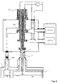
- FIG. 1 shows a schematic view of an inventive NMR apparatus comprising a cryocooler for commonly cooling a cryostat and an NMR probe head;
- FIG. 2 shows a schematic section of an inventive NMR apparatus with a three-stage cryocooler and a heat-transferring metallic device for cooling a first cryocontainer and a pipe conduit connected to a cavity for cooling a further cryocontainer;
- FIG. 3 shows a schematic section of an inventive NMR apparatus with a three-stage cryocooler and a pipe conduit connected to the cavity for cooling a first cryocontainer, and a further line for cooling a further cryocontainer;
- FIG. 4 shows a schematic section of an inventive NMR apparatus with a three-stage cryocooler and a pipe conduit, connected to the cavity, for cooling a first cryocontainer and a further line for cooling a radiation shield;
- FIG. 5 shows a schematic section of an inventive NMR apparatus with a two-stage cryocooler and a common cooling circuit for cooling a first cryocontainer and an NMR probe head, and a pipe conduit, connected to a cavity, for cooling a further cryocontainer;
- FIG. 6 shows a schematic section of an inventive NMR apparatus with a three-stage cryocooler and a pipe conduit, connected to a cavity, for cooling a first cryocontainer, and a common cooling circuit for cooling a radiation shield and an NMR probe head;
- FIG. 7 shows a schematic section of an inventive NMR apparatus with a two-stage pulse tube cooler with variable temperature tapping for a cooling circuit of an NMR probe head and with a line combined from two lines for cooling a first cryocontainer, and with a further line for cooling a further cryocontainer;
- FIG. 8 shows a schematic section of an inventive NMR apparatus with a three-stage cryocooler and a separate cooling circuit for a preamplifier of an NMR probe head.
- the inventive NMR apparatus shown in FIG. 1 permits simultaneous cooling of an NMR probe head 1 and a cryostat 9 using one single cooling device which is more compact and less expensive than two separate cooling devices.
- a cold head 4 of a cryocooler which is operated by a compressor 5 , is accommodated in an external thermally insulated evacuated housing 6 .
- the external arrangement of the cryocooler eliminates transfer of mechanical or magnetic disturbances of the cryocooler into the working volume of the NMR magnet system. This permits use of low-vibration pulse tube coolers and also Gifford-McMahon coolers, which cause greater disturbances. Since the cold head 4 of the cryocooler is externally arranged, its geometry is moreover not subjected to any limits.
- the housing 6 is connected to the NMR probe head 1 via one or more transfer lines 7 .
- the housing 6 is mounted to the stand 8 and disposed directly above the cryostat 9 of the NMR apparatus.
- bellows 10 are provided between the housing 6 and the cryostat 9 . Simultaneous cooling of the cryostat 9 and the NMR probe head 1 using one single cold head 4 maximally utilizes the given refrigeration capacity of the cryocooler and realizes a compact cooling unit.
- FIG. 2 shows a schematic section of an inventive NMR apparatus.
- a heat-transferring device in the form of a metallic connection 11 (e.g. of copper) having a high thermal conductivity is provided to cool a first cryocontainer 2 , wherein one end of the connection 11 is connected to the coldest cold stage 12 a of a three-stage cold head 4 a, the other end projecting into the first cryocontainer 2 .
- the connection 11 is guided into the first cryocontainer 2 via a suspension tube 29 a thereof.
- the cryogenic vapor in the first cryocontainer 2 is liquefied at the end, projecting into the first cryocontainer 2 , of the metallic connection 11 having a high thermal conductivity, as the cryogen gives off heat to the connection 11 and thereby to the cold head 4 a.
- the connection 11 having a high thermal conductivity is partially designed in the form of flexible strands 13 , thereby effecting a soft connection.
- Helium at a temperature of approximately 4.2 K, is preferably used as the cryogen in the first cryocontainer 2 .
- a further cryocontainer 3 is cooled using a line 14 , in particular a pipe conduit which is connected to a cavity 15 , wherein the cavity 15 is in contact with the first cold stage 18 a of the cold head 4 a.
- the line 14 is guided through a suspension tube 29 c of the further cryocontainer 3 and terminates in the further cryocontainer 3 .
- Evaporating cryogen e.g. nitrogen, is guided from the further cryocontainer 3 through the line 14 into the cavity 15 , where the cryogen is liquefied via heat exchange with the cold head 4 a, and is subsequently returned to the further cryocontainer 3 through the line 14 .
- the line 14 may also be designed as a concentric line which consists of two tubes: The cryogen vapor rises in the outer pipe gap to the cavity 15 , and the liquefied cryogen returns to the further cryocontainer 3 via the inner tube.
- the line is advantageously also provided with vacuum insulation, at least in sections or along its entire length.
- the cold head 4 a also cools an RF resonator 16 and a preamplifier 17 of the NMR probe head 1 .
- the NMR probe head 1 is thereby not directly connected to the cold head 4 a but is in contact therewith via a refrigerant that flows in a closed circuit.
- the transfer line 7 (consisting of four individual line strands) connects the NMR probe head 1 to the first cold stage 18 a and the second cold stage 19 a of the cold head 4 a, wherein the first cold stage 18 a of the cold head 4 a is at approximately 65 K and the second cold stage 19 a at approximately 12 K.
- Both cold stages 18 a, 19 a have thermal contact surfaces for giving off cold, which may be connected e.g. to heat exchangers to transfer heat from the refrigerant of the cooling circuit to the cold head 4 a.
- the refrigerant (e.g. helium) is circulated in the cooling circuit of the NMR probe head 1 using the cryocooler compressor 5 .
- the refrigerant is initially precooled using a first counter flow heat exchanger 21 and subsequently at the first cold stage 18 a of the cold head 4 a to 65 K before reaching the second counter flow heat exchanger 22 and finally the second cold stage 19 a, where the refrigerant is cooled to 12 K.
- the cooled refrigerant is supplied via the transfer line 7 to the RF resonator 16 , which cools the latter to approximately 15 K.
- the refrigerant heated to 15 K subsequently reaches the housing 6 via the transfer line 7 and the second counter flow heat exchanger 22 .
- part of the refrigerant is supplied via the transfer line 7 to the preamplifier 17 , thereby cooling it to approximately 77 K.
- the refrigerant heated to 77 K subsequently flows to the housing 6 via the transfer line 7 , where it is mixed with the residual flow from the second counter flow heat exchanger 22 and is guided to the compressor 5 via the first counter flow heat exchanger 21 .
- the first cryocontainer 2 , the additional cryocontainer 3 and the NMR probe head 1 are thereby cooled using one single cold head 4 a via three separate cold transmitting mechanisms.
- the housing 6 with cold head 4 a is connected to the cryostat 9 and the NMR probe head 1 in a gas-tight manner via the bellows 10 to eliminate, or at least substantially dampen, transfer of vibrations from the cold head 4 a to the cryostat 9 and the NMR probe head 1 .
- FIG. 3 shows an embodiment of the invention, with which the first cryocontainer 2 is cooled via a line 14 , which is connected to a cavity 15 .
- a further line 23 a is inserted into the further cryocontainer 3 , which is guided to the first cold stage 18 a of the cold head 4 a and is in contact therewith.
- Evaporated cryogen which is heated to approximately surrounding temperature, is guided to the first cold stage 18 a of the cold head 4 a via the further line 23 a. Heat is transferred from the cryogen to the cold stage 18 a at the first cold stage 18 a to cool and liquefy the cryogen, returning it to the further cryocontainer 3 .
- a radiation shield 24 is cooled instead of a further cryocontainer 3 .
- a further line 23 b forms a closed circuit in which a refrigerant is cooled at the first cold stage 18 a of the cold head 4 a and guided to a heat exchanger 25 .
- the heat exchanger 25 is in contact with the radiation shield 24 , thereby picking up heat from the radiation shield 24 .
- the cooling circuit of the further line 23 b is thereby driven through free convection.
- the use of a circulating pump is also feasible.
- cooling of the first cryocontainer 2 is directly combined with cooling of the NMR probe head 1 and is realized in one single cooling circuit.
- a two-stage cold head 4 b with cold stages 18 b, 12 b is thereby provided for cooling, wherein the coldest cold stage 12 b has a temperature of approximately 12 K.
- the refrigerant (helium) of the closed circuit is cooled at the cold stages 18 b, 12 b of the cold head 4 b and supplied to the components to be cooled (first cryocontainer, 2 , RF resonator 16 , preamplifier 17 ).
- the refrigerant of the cooling circuit is guided, after cooling, from the coldest cold stage 12 b of the cold head 4 b in two counter flow heat exchangers 26 into the first cryocontainer 2 , in which a further line 23 c comes in contact with the cryogen in the first cryocontainer 2 .
- the refrigerant flow is divided so that part thereof passes through further counter flow heat exchangers 26 and another part is cooled in devices 27 for intermediate expansion, e.g. Joule Thomson valves.
- Cooling with isenthalpic pressure reduction is effected when the refrigerant has a positive integral Joule-Thomson coefficient in the predetermined initial and final states.
- the cooled partial flows precool the partial flow in the counter flow heat exchangers 26 supplied to the first cryocontainer 2 .
- Final expansion to a pressure slightly below the pressure in the first cryocontainer finally partially liquefies the precooled partial flow.
- the refrigerant picks up heat from the first cryocontainer 2 and subsequently returns in the form of saturated vapor or slightly overheated vapor through the further counter flow heat exchanger 26 , is thereby heated and guided into the NMR probe head 1 to cool the RF resonator 16 and preamplifier 17 .
- a further (smaller) compressor 20 is required to re-compress the refrigerant to the low-pressure level of the refrigeration compressor 5 .
- the cooling circuit may also be completely separated from the refrigeration compressor 5 , using an additional separate compressor that compresses the refrigerant from ambient pressure to a high pressure required for process control.
- Combination of cooling of the first cryocontainer 2 and cooling of the NMR probe head 1 is disadvantageous in that individual cooling of both partial systems is difficult. Interruption of probe head cooling and continuing cooling of the cryocontainer 2 would require further fittings and lines in the cooling circuit, which increases equipment expense.
- the cooling circuits of the NMR probe head 1 and the radiation shield 24 are coupled to form a closed cooling circuit.
- the preamplifier 17 as well as the radiation shield 24 must be cooled to approximately 77K and for this reason, part of the refrigerant used for probe head cooling is branched off from the main flow after passage through the RF resonator 16 and the second counter flow heat exchanger 22 , and guided in the further line 23 d to the radiation shield 24 , while the other part of the refrigerant passes through the preamplifier 17 .
- the refrigerant supplied to the radiation shield 24 picks up heat input into the radiation shield 24 via the heat exchanger 25 , and is joined with the return line from the preamplifier 17 within the housing 6 . Independent cooling of the radiation shield 24 and NMR probe head 1 is no longer possible in the embodiment of FIG. 6 .
- a cold head 4 c of a pulse tube cooler comprising two cold stages 18 c, 12 c is particularly advantageous.
- the refrigerant of the circuit for cooling the probe head 1 and the cryogen evaporated and heated in the first cryocontainer 2 may then be brought into thermal contact with the regenerator tube 28 of the coldest cold stage 12 c of the pulse tube cooler ( FIG. 7 ).
- the cryogen evaporated through heat input and heated in the suspension tubes 29 a and 29 b is guided through lines 23 e, 30 into the housing 6 , where it is mixed and guided to the first cold stage 18 c of the cold head 4 c, where it is cooled to approximately 65 K.
- the cryogen is subsequently further cooled along the regenerator tube 28 and finally liquefied in contact with the coldest cold stage 12 c of the cold head 4 c and returned into the first cryocontainer 2 , thereby cooling the suspension tubes 29 a and 29 b and reducing the heat input into the first cryocontainer 2 .
- the refrigerant used for cooling the RF resonator 16 need not be cooled to the temperature of the coldest cold stage 12 c (4.2 K). For this reason, the refrigerant of the cooling circuit of the NMR probe head 1 of the embodiment of FIG. 7 is precooled in the counter flow heat exchanger 21 with the refrigerant discharged from the NMR probe head 1 , subsequently precooled at the first cold stage 18 c of the cold head 4 c, and finally cooled along a section of the regenerator tube 28 of the coldest cold stage 12 c to the required temperature.
- the refrigerant of the cooling circuit of the NMR probe head 1 is thereby not guided to the cold end of the coldest cold stage 12 c of the cold head 4 c but merely to one location of the regenerator tube 28 where the refrigerant has a temperature which is suited for cooling the RF resonator 16 and the preamplifier 17 of the NMR probe head 1 .
- the length of the contact surface between the refrigerant and the regenerator tube 28 can be freely selected which permits optimization of the cooling temperature of the refrigerant in a temperature range between the temperature of the coldest cold stage 12 c (4.2 K) and the first cold stage 18 c (e.g. 65 K) as desired.
- the additional heat input into the regenerator tube 28 of the coldest cold stage 12 c impairs the refrigeration capacity of the coldest cold stage 12 c of the pulse tube cooler.
- the thermodynamic efficiency of the overall system can thereby even be increased.
- the number of counter flow heat exchangers may also be reduced.
- a separate closed cooling circuit 31 may, however, also be provided for cooling the preamplifier 17 of the NMR probe head 1 ( FIG. 8 ).
- This cooling circuit 31 may be operated with a refrigerant, which boils at higher temperatures (e.g. nitrogen), since the preamplifier 17 must be cooled only to approximately 77 K.
- the inventive NMR apparatus cools the cryocontainers 2 , 3 , the preamplifier 17 and the RF resonator 16 using one single cold head 4 a and four separate cold coupling mechanisms. This permits e.g. heating of the NMR probe head 1 without switching off the cryocooler (and thereby cooling of the magnet).
- the inventive device In total, one obtains an NMR apparatus with efficient cooling and improved vibration decoupling, at the same time minimizing cryogen loss.
- the inventive device also reduces the influence on the magnetic field of the magnet system by the magnetic regenerator materials of the cold head (and vice versa).
- NMR measurements can be continued even when cooling of the cryostat has been interrupted, since the cryogenic liquids at least temporarily ensure cooling of the magnet.
Landscapes
- Physics & Mathematics (AREA)
- Engineering & Computer Science (AREA)
- Condensed Matter Physics & Semiconductors (AREA)
- General Physics & Mathematics (AREA)
- Chemical & Material Sciences (AREA)
- Combustion & Propulsion (AREA)
- Mechanical Engineering (AREA)
- Thermal Sciences (AREA)
- General Engineering & Computer Science (AREA)
- Electromagnetism (AREA)
- Containers, Films, And Cooling For Superconductive Devices (AREA)
- Magnetic Resonance Imaging Apparatus (AREA)
Abstract
Description
- 1 NMR probe head
- 2 first cryocontainer
- 3 additional cryocontainer
- 4 cold head
- 4 a three-stage cold head
- 4 b two-stage cold head
- 4 c two-stage cold head of a pulse tube cooler
- 5 refrigeration compressor
- 6 evacuated housing
- 7 transfer line
- 8 stand
- 9 cryostat
- 10 bellows
- 11 connection with a high thermal conductivity
- 12 a coldest cold stage of the three-stage cold head
- 12 b coldest cold stage of the two-stage cold head
- 12 c coldest cold stage of the two-stage cold head of the pulse tube cooler
- 13 strands
- 14 line
- 15 cavity
- 16 RF resonator
- 17 preamplifier
- 18 a first cold stage of the three-stage cold head
- 18 b first cold stage of the two-stage cold head
- 18 c first cold stage of the two-stage cold head of the pulse tube cooler
- 19 a second cold stage of the three-stage cold head
- 20 further compressor
- 21 first counter flow heat exchanger
- 23 a further line of the cooling circuit of the additional cryocontainer
- 23 b further line of the cooling circuit of the radiation shield
- 23 c further line of the cooling circuit of the pulse tube cooler
- 23 d further line of the cooling circuit of the radiation shield
- 23 e further line of the cooling circuit of the first cryocontainer
- 24 radiation shield
- 25 heat exchanger
- 26 further counter flow heat exchanger
- 27 device for intermediate expansion
- 28 regenerator tube of the coldest cold stage
- 29 a suspension tube of the first cryocontainer
- 29 b further suspension tube of the first cryocontainer
- 29 c suspension tube of the further cryocontainer
- 30 connecting line
- 31 cooling circuit for preamplifier
Claims (31)
Applications Claiming Priority (2)
| Application Number | Priority Date | Filing Date | Title |
|---|---|---|---|
| DE102005041383.8 | 2005-09-01 | ||
| DE102005041383A DE102005041383B4 (en) | 2005-09-01 | 2005-09-01 | NMR apparatus with co-cooled probe head and cryocontainer and method of operation thereof |
Publications (2)
| Publication Number | Publication Date |
|---|---|
| US20070107445A1 US20070107445A1 (en) | 2007-05-17 |
| US7474099B2 true US7474099B2 (en) | 2009-01-06 |
Family
ID=37103289
Family Applications (1)
| Application Number | Title | Priority Date | Filing Date |
|---|---|---|---|
| US11/509,778 Active 2027-07-10 US7474099B2 (en) | 2005-09-01 | 2006-08-25 | NMR apparatus with commonly cooled probe head and cryogenic container and method for the operation thereof |
Country Status (4)
| Country | Link |
|---|---|
| US (1) | US7474099B2 (en) |
| EP (1) | EP1760480A1 (en) |
| JP (1) | JP4336359B2 (en) |
| DE (1) | DE102005041383B4 (en) |
Cited By (12)
| Publication number | Priority date | Publication date | Assignee | Title |
|---|---|---|---|---|
| US20080180100A1 (en) * | 2006-11-20 | 2008-07-31 | Ryuya Ando | Superconducting magnet with refrigerator and magnetic resonance imaging apparatus using the same |
| US20090301129A1 (en) * | 2008-06-08 | 2009-12-10 | Wang Nmr Inc. | Helium and nitrogen reliquefying apparatus |
| US20100005814A1 (en) * | 2008-07-03 | 2010-01-14 | Bruker Biospin Gmbh | Method for cooling a cryostat configuration during transport and cryostat configuration with transport cooler unit |
| US20100079143A1 (en) * | 2008-09-30 | 2010-04-01 | Burns Sean T | Demountable cryogenic nmr connection assembly systems and methods |
| US20120242336A1 (en) * | 2011-03-25 | 2012-09-27 | Philippe Stauffenegger | Compact cryogenic NMR sensor with integrated active cooling device |
| US8575932B2 (en) | 2008-01-08 | 2013-11-05 | The University Of Georgia Research Foundation, Inc. | Upper stack for a nuclear magnetic resonance spectrometer aaparatus and associated method of operating a nuclear magnetic resonance spectrometer apparatus |
| WO2014144626A3 (en) * | 2013-03-15 | 2014-12-11 | Endocare, Inc. | Cryogenic system and methods |
| US20150300719A1 (en) * | 2014-04-16 | 2015-10-22 | Victoria Link Ltd | Cryogenic gas circulation and heat exchanger |
| US20160215921A1 (en) * | 2013-03-14 | 2016-07-28 | Japan Superconductor Technology Inc. | Superconducting magnet apparatus |
| US10184994B2 (en) | 2013-05-03 | 2019-01-22 | Quantum Valley Investment Fund LP | Polarizing a spin ensemble for magnetic resonance imaging |
| US10197643B2 (en) | 2013-05-03 | 2019-02-05 | Quantum Valley Investment Fund LP | Transferring spin polarization |
| EP3901543A1 (en) * | 2020-04-23 | 2021-10-27 | Honeywell International Inc. | Testing environment for cryogenic chamber |
Families Citing this family (24)
| Publication number | Priority date | Publication date | Assignee | Title |
|---|---|---|---|---|
| GB2443674B (en) * | 2006-10-04 | 2008-11-26 | Oxford Instr Superconductivity | Flow-cooled magnet system |
| FR2914050B1 (en) * | 2007-03-21 | 2012-12-28 | Air Liquide | REFRIGERATOR AT LOW OR VERY LOW TEMPERATURE AND REFRIGERATION PROCESS |
| WO2009086430A2 (en) * | 2007-12-28 | 2009-07-09 | D-Wave Systems Inc. | Systems, methods, and apparatus for cryogenic refrigeration |
| EP2310768B1 (en) * | 2008-05-21 | 2018-12-26 | Brooks Automation, Inc. | Linear drive cryogenic refrigerator |
| FR2933475B1 (en) * | 2008-07-04 | 2010-08-27 | Snecma | CRYOGENIC LIQUID STORAGE SYSTEM FOR SPACE ENGINE |
| JP5746626B2 (en) * | 2008-09-09 | 2015-07-08 | コーニンクレッカ フィリップス エヌ ヴェ | Heat exchanger with horizontal fins for cryogenic reliquefaction refrigerator. |
| WO2010032171A1 (en) * | 2008-09-22 | 2010-03-25 | Koninklijke Philips Electronics, N.V. | Neck deicer for liquid helium recondensor of magnetic resonance system |
| DE102011005888B4 (en) * | 2011-03-22 | 2014-01-09 | Bruker Biospin Ag | Cooling of a Cryo Probe Head in a Magnetic Resonance Resonance Equipment |
| DE102011115303B4 (en) * | 2011-09-29 | 2013-06-27 | Entropy GmbH | Cryogenic device |
| US11099247B2 (en) | 2012-01-27 | 2021-08-24 | Bruker Biospin Corporation | Ultra-low vibration cryogen-free cryostat for an electron paramagnetic resonance system |
| CN103077797B (en) * | 2013-01-06 | 2016-03-30 | 中国科学院电工研究所 | For the superconducting magnet system of head imaging |
| JP2015079846A (en) * | 2013-10-17 | 2015-04-23 | 株式会社日立製作所 | Superconducting magnetic device |
| GB2545139B (en) * | 2014-04-16 | 2018-05-30 | Siemens Healthcare Ltd | Thermally disconnecting a cryogenic vessel from a refrigerator |
| DE102014214819B3 (en) * | 2014-07-29 | 2015-08-20 | Bruker Biospin Gmbh | Pulse tube cooler system with force-compensated rotary valve line |
| US10378803B2 (en) | 2014-08-08 | 2019-08-13 | D-Wave Systems Inc. | Systems and methods for electrostatic trapping of contaminants in cryogenic refrigeration systems |
| CN106298152A (en) * | 2015-05-11 | 2017-01-04 | 通用电气公司 | Superconducting magnet cooling system |
| DE102015212314B3 (en) | 2015-07-01 | 2016-10-20 | Bruker Biospin Gmbh | Cryostat with active neck tube cooling by a second cryogen |
| DE102016214731B3 (en) * | 2016-08-09 | 2017-07-27 | Bruker Biospin Ag | NMR apparatus with superconducting magnet arrangement and cooled probe components |
| DE102016214728B3 (en) | 2016-08-09 | 2017-08-03 | Bruker Biospin Ag | NMR apparatus with cooled probe head components insertable through a vacuum lock in the cryostats of a superconducting magnet assembly, and methods of assembling and removing same |
| DE102019203341A1 (en) | 2019-03-12 | 2020-09-17 | Pressure Wave Systems Gmbh | Cryostat |
| CN111928519B (en) * | 2020-07-17 | 2021-12-31 | 同济大学 | Superconducting magnet and composite magnetic refrigerator |
| CN114068132B (en) * | 2021-10-15 | 2023-05-12 | 江苏美时医疗技术有限公司 | Nuclear magnetic resonance ultra-high field magnet circulation refrigerating device based on liquid helium circulation |
| KR102390188B1 (en) * | 2021-11-01 | 2022-04-26 | 주식회사 태진중공업 | Liquid hydrogen storage system |
| CN115290690B (en) * | 2022-06-22 | 2023-06-27 | 安徽万瑞冷电科技有限公司 | High-low temperature experiment testing arrangement |
Citations (31)
| Publication number | Priority date | Publication date | Assignee | Title |
|---|---|---|---|---|
| US4935714A (en) * | 1988-07-05 | 1990-06-19 | General Electric Company | Low thermal conductance support for a radiation shield in a MR magnet |
| US5187938A (en) * | 1989-05-18 | 1993-02-23 | Spectrospin Ag | Method and a device for precooling the helium tank of a cryostat |
| US5379600A (en) * | 1992-03-27 | 1995-01-10 | Mitsubishi Denki Kabushiki Kaisha | Superconducting magnet and method for assembling the same |
| US5381666A (en) * | 1990-06-08 | 1995-01-17 | Hitachi, Ltd. | Cryostat with liquefaction refrigerator |
| US5412363A (en) * | 1991-12-20 | 1995-05-02 | Applied Superconetics, Inc. | Open access superconducting MRI magnet |
| US5586437A (en) * | 1995-09-06 | 1996-12-24 | Intermagnetics General Corporation | MRI cryostat cooled by open and closed cycle refrigeration systems |
| US5737927A (en) | 1996-03-18 | 1998-04-14 | Kabushiki Kaisha Toshiba | Cryogenic cooling apparatus and cryogenic cooling method for cooling object to very low temperatures |
| US5814992A (en) * | 1995-12-20 | 1998-09-29 | Spectrospin Ag | NMR probe head with cryogenically cooled preampifiers |
| JPH10321430A (en) | 1997-05-23 | 1998-12-04 | Mitsubishi Electric Corp | Superconductive electromagnet device |
| JPH1187130A (en) | 1997-09-02 | 1999-03-30 | Toshiba Corp | Superconducting magnet |
| US5889456A (en) * | 1997-05-16 | 1999-03-30 | Spectrospin Ag | NMR measuring device having a cooled probe head |
| US5966944A (en) * | 1997-04-09 | 1999-10-19 | Aisin Seiki Kabushiki Kaisha | Superconducting magnet system outfitted with cooling apparatus |
| US6181228B1 (en) | 1999-11-09 | 2001-01-30 | General Electric Company | Superconductive magnet including a cryocooler coldhead |
| US6204665B1 (en) * | 1997-10-10 | 2001-03-20 | Bruker Ag | NMR probe head with integrated remote tuning |
| JP2002124410A (en) | 2000-10-17 | 2002-04-26 | Japan Magnet Technol Kk | Cooling system for superconducting magnet device |
| US6437570B2 (en) * | 2000-02-12 | 2002-08-20 | Bruker Biospin Ag | Cooled NMR probe head with uniform temperature control of the sample |
| US6441617B2 (en) * | 2000-02-12 | 2002-08-27 | Bruker Biospin Ag | Cooled NMR probe head with thermal insulation of the sample |
| US6466019B2 (en) * | 2000-02-12 | 2002-10-15 | Bruker Biospin Ag | Cooled NMR probe head comprising a device for centering the sample |
| JP2003009286A (en) | 2001-06-26 | 2003-01-10 | Murata Mfg Co Ltd | Piezoelectric electroacoustic transducer and its manufacturing method |
| WO2003023433A1 (en) | 2001-09-06 | 2003-03-20 | Oxford Instruments Superconductivity Limited | Apparatus for use in nmr system |
| US6677751B1 (en) * | 1999-09-28 | 2004-01-13 | Bruker Biospin Ag | Connection system between cryo-cooling systems and cooled NMR probe heads |
| US6686740B2 (en) * | 2001-03-09 | 2004-02-03 | Bruker Biospin Ag | Device for the transport and exact positioning of a sample tube in a high-resolution NMR spectrometer |
| US6727699B2 (en) * | 2001-02-01 | 2004-04-27 | Bruker Biospin Gmbh | Superconducting magnet system |
| US6807812B2 (en) * | 2003-03-19 | 2004-10-26 | Ge Medical Systems Global Technology Company, Llc | Pulse tube cryocooler system for magnetic resonance superconducting magnets |
| EP1560035A1 (en) | 2004-01-28 | 2005-08-03 | Oxford Instruments Superconductivity Limited | Magnetic field generating assembly |
| US7030613B2 (en) * | 2003-09-30 | 2006-04-18 | Hitachi, Ltd. | Nuclear magnetic resonance measuring apparatus |
| US20060130493A1 (en) * | 2004-12-17 | 2006-06-22 | Bruker Biospin Gmbh | NMR spectrometer with common refrigerator for cooling an NMR probe head and cryostat |
| US7141979B2 (en) * | 2003-09-02 | 2006-11-28 | Bruker Biospin Ag | Cryo head with a plurality of heat exchangers for cooling the RF coils or resonators |
| US7157999B2 (en) * | 2004-02-16 | 2007-01-02 | Bruker Biospin Gmbh | Low drift superconducting high field magnet system |
| US7183769B2 (en) * | 2004-02-05 | 2007-02-27 | Bruker Biospin Gmbh | Superconducting magnet system with drift compensation |
| US7408353B2 (en) * | 2006-05-03 | 2008-08-05 | Bruker Biospin Ag | Cooled NMR probe head which can be coupled |
Family Cites Families (2)
| Publication number | Priority date | Publication date | Assignee | Title |
|---|---|---|---|---|
| JP2004219361A (en) * | 2003-01-17 | 2004-08-05 | Jeol Ltd | Nuclear magnetic resonance probe |
| DE102004053973B3 (en) * | 2004-11-09 | 2006-07-20 | Bruker Biospin Ag | NMR spectrometer with refrigerator cooling |
-
2005
- 2005-09-01 DE DE102005041383A patent/DE102005041383B4/en active Active
-
2006
- 2006-08-25 US US11/509,778 patent/US7474099B2/en active Active
- 2006-08-29 EP EP06017951A patent/EP1760480A1/en not_active Ceased
- 2006-09-01 JP JP2006237877A patent/JP4336359B2/en active Active
Patent Citations (33)
| Publication number | Priority date | Publication date | Assignee | Title |
|---|---|---|---|---|
| US4935714A (en) * | 1988-07-05 | 1990-06-19 | General Electric Company | Low thermal conductance support for a radiation shield in a MR magnet |
| US5187938A (en) * | 1989-05-18 | 1993-02-23 | Spectrospin Ag | Method and a device for precooling the helium tank of a cryostat |
| US5381666A (en) * | 1990-06-08 | 1995-01-17 | Hitachi, Ltd. | Cryostat with liquefaction refrigerator |
| US5412363A (en) * | 1991-12-20 | 1995-05-02 | Applied Superconetics, Inc. | Open access superconducting MRI magnet |
| US5379600A (en) * | 1992-03-27 | 1995-01-10 | Mitsubishi Denki Kabushiki Kaisha | Superconducting magnet and method for assembling the same |
| US5586437A (en) * | 1995-09-06 | 1996-12-24 | Intermagnetics General Corporation | MRI cryostat cooled by open and closed cycle refrigeration systems |
| US5814992A (en) * | 1995-12-20 | 1998-09-29 | Spectrospin Ag | NMR probe head with cryogenically cooled preampifiers |
| US5737927A (en) | 1996-03-18 | 1998-04-14 | Kabushiki Kaisha Toshiba | Cryogenic cooling apparatus and cryogenic cooling method for cooling object to very low temperatures |
| US5966944A (en) * | 1997-04-09 | 1999-10-19 | Aisin Seiki Kabushiki Kaisha | Superconducting magnet system outfitted with cooling apparatus |
| US5889456A (en) * | 1997-05-16 | 1999-03-30 | Spectrospin Ag | NMR measuring device having a cooled probe head |
| JPH10321430A (en) | 1997-05-23 | 1998-12-04 | Mitsubishi Electric Corp | Superconductive electromagnet device |
| JPH1187130A (en) | 1997-09-02 | 1999-03-30 | Toshiba Corp | Superconducting magnet |
| US6204665B1 (en) * | 1997-10-10 | 2001-03-20 | Bruker Ag | NMR probe head with integrated remote tuning |
| US6677751B1 (en) * | 1999-09-28 | 2004-01-13 | Bruker Biospin Ag | Connection system between cryo-cooling systems and cooled NMR probe heads |
| US6181228B1 (en) | 1999-11-09 | 2001-01-30 | General Electric Company | Superconductive magnet including a cryocooler coldhead |
| US6246308B1 (en) | 1999-11-09 | 2001-06-12 | General Electric Company | Superconductive magnet including a cryocooler coldhead |
| US6437570B2 (en) * | 2000-02-12 | 2002-08-20 | Bruker Biospin Ag | Cooled NMR probe head with uniform temperature control of the sample |
| US6441617B2 (en) * | 2000-02-12 | 2002-08-27 | Bruker Biospin Ag | Cooled NMR probe head with thermal insulation of the sample |
| US6466019B2 (en) * | 2000-02-12 | 2002-10-15 | Bruker Biospin Ag | Cooled NMR probe head comprising a device for centering the sample |
| JP2002124410A (en) | 2000-10-17 | 2002-04-26 | Japan Magnet Technol Kk | Cooling system for superconducting magnet device |
| US6727699B2 (en) * | 2001-02-01 | 2004-04-27 | Bruker Biospin Gmbh | Superconducting magnet system |
| US6686740B2 (en) * | 2001-03-09 | 2004-02-03 | Bruker Biospin Ag | Device for the transport and exact positioning of a sample tube in a high-resolution NMR spectrometer |
| JP2003009286A (en) | 2001-06-26 | 2003-01-10 | Murata Mfg Co Ltd | Piezoelectric electroacoustic transducer and its manufacturing method |
| WO2003023433A1 (en) | 2001-09-06 | 2003-03-20 | Oxford Instruments Superconductivity Limited | Apparatus for use in nmr system |
| US6807812B2 (en) * | 2003-03-19 | 2004-10-26 | Ge Medical Systems Global Technology Company, Llc | Pulse tube cryocooler system for magnetic resonance superconducting magnets |
| US7141979B2 (en) * | 2003-09-02 | 2006-11-28 | Bruker Biospin Ag | Cryo head with a plurality of heat exchangers for cooling the RF coils or resonators |
| US7030613B2 (en) * | 2003-09-30 | 2006-04-18 | Hitachi, Ltd. | Nuclear magnetic resonance measuring apparatus |
| US7126335B2 (en) * | 2003-09-30 | 2006-10-24 | Hitachi, Ltd. | Nuclear magnetic resonance measuring apparatus |
| EP1560035A1 (en) | 2004-01-28 | 2005-08-03 | Oxford Instruments Superconductivity Limited | Magnetic field generating assembly |
| US7183769B2 (en) * | 2004-02-05 | 2007-02-27 | Bruker Biospin Gmbh | Superconducting magnet system with drift compensation |
| US7157999B2 (en) * | 2004-02-16 | 2007-01-02 | Bruker Biospin Gmbh | Low drift superconducting high field magnet system |
| US20060130493A1 (en) * | 2004-12-17 | 2006-06-22 | Bruker Biospin Gmbh | NMR spectrometer with common refrigerator for cooling an NMR probe head and cryostat |
| US7408353B2 (en) * | 2006-05-03 | 2008-08-05 | Bruker Biospin Ag | Cooled NMR probe head which can be coupled |
Cited By (23)
| Publication number | Priority date | Publication date | Assignee | Title |
|---|---|---|---|---|
| US7714574B2 (en) * | 2006-11-20 | 2010-05-11 | Hitachi, Ltd. | Superconducting magnet with refrigerator and magnetic resonance imaging apparatus using the same |
| US20080180100A1 (en) * | 2006-11-20 | 2008-07-31 | Ryuya Ando | Superconducting magnet with refrigerator and magnetic resonance imaging apparatus using the same |
| US8575932B2 (en) | 2008-01-08 | 2013-11-05 | The University Of Georgia Research Foundation, Inc. | Upper stack for a nuclear magnetic resonance spectrometer aaparatus and associated method of operating a nuclear magnetic resonance spectrometer apparatus |
| US20090301129A1 (en) * | 2008-06-08 | 2009-12-10 | Wang Nmr Inc. | Helium and nitrogen reliquefying apparatus |
| US20100005814A1 (en) * | 2008-07-03 | 2010-01-14 | Bruker Biospin Gmbh | Method for cooling a cryostat configuration during transport and cryostat configuration with transport cooler unit |
| US8448455B2 (en) | 2008-07-03 | 2013-05-28 | Bruker Biospin Gmbh | Method for cooling a cryostat configuration during transport and cryostat configuration with transport cooler unit |
| US20100079143A1 (en) * | 2008-09-30 | 2010-04-01 | Burns Sean T | Demountable cryogenic nmr connection assembly systems and methods |
| US7812606B2 (en) * | 2008-09-30 | 2010-10-12 | Varian, Inc. | Demountable cryogenic NMR connection assembly systems and methods |
| US20120242336A1 (en) * | 2011-03-25 | 2012-09-27 | Philippe Stauffenegger | Compact cryogenic NMR sensor with integrated active cooling device |
| US8896312B2 (en) * | 2011-03-25 | 2014-11-25 | Bruker Biospin Ag | Compact cryogenic NMR sensor with integrated active cooling device |
| US20160215921A1 (en) * | 2013-03-14 | 2016-07-28 | Japan Superconductor Technology Inc. | Superconducting magnet apparatus |
| US9777883B2 (en) * | 2013-03-14 | 2017-10-03 | Japan Superconductor Technology Inc. | Superconducting magnet apparatus |
| WO2014144626A3 (en) * | 2013-03-15 | 2014-12-11 | Endocare, Inc. | Cryogenic system and methods |
| US11026737B2 (en) | 2013-03-15 | 2021-06-08 | Endocare, Inc. | Cryogenic system and methods |
| US11849989B2 (en) | 2013-03-15 | 2023-12-26 | Varian Medical Systems, Inc. | Cryogenic system and methods |
| US10184994B2 (en) | 2013-05-03 | 2019-01-22 | Quantum Valley Investment Fund LP | Polarizing a spin ensemble for magnetic resonance imaging |
| US10197641B2 (en) | 2013-05-03 | 2019-02-05 | Quantum Valley Investment Fund LP | Using a cavity to polarize a spin ensemble |
| US10197642B2 (en) | 2013-05-03 | 2019-02-05 | Quantum Valley Investment Fund LP | Using a thermally-isolated cavity to polarize a spin ensemble |
| US10197643B2 (en) | 2013-05-03 | 2019-02-05 | Quantum Valley Investment Fund LP | Transferring spin polarization |
| US10371767B2 (en) | 2013-05-03 | 2019-08-06 | Quantum Valley Investment Fund LP | Efficient spin polarization |
| US20150300719A1 (en) * | 2014-04-16 | 2015-10-22 | Victoria Link Ltd | Cryogenic gas circulation and heat exchanger |
| EP3901543A1 (en) * | 2020-04-23 | 2021-10-27 | Honeywell International Inc. | Testing environment for cryogenic chamber |
| US11674738B2 (en) | 2020-04-23 | 2023-06-13 | Quantinuum Llc | Testing environment for cryogenic chamber |
Also Published As
| Publication number | Publication date |
|---|---|
| DE102005041383B4 (en) | 2007-09-27 |
| DE102005041383A1 (en) | 2007-03-22 |
| JP4336359B2 (en) | 2009-09-30 |
| US20070107445A1 (en) | 2007-05-17 |
| EP1760480A1 (en) | 2007-03-07 |
| JP2007064984A (en) | 2007-03-15 |
Similar Documents
| Publication | Publication Date | Title |
|---|---|---|
| US7474099B2 (en) | NMR apparatus with commonly cooled probe head and cryogenic container and method for the operation thereof | |
| US7430871B2 (en) | NMR spectrometer with a common refrigerator for cooling an NMR probe head and cryostat | |
| JP4417247B2 (en) | MRI system with superconducting magnet and refrigeration unit | |
| JP4352040B2 (en) | Refrigerator cooled NMR spectrometer | |
| JP3996935B2 (en) | Cryostat structure | |
| US7191601B2 (en) | Magnetic field generating assembly | |
| EP1586833A2 (en) | Cooling apparatus | |
| US10203068B2 (en) | Method and device for precooling a cryostat | |
| US20070051116A1 (en) | Device for loss-free cryogen cooling of a cryostat configuration | |
| US20060130493A1 (en) | NMR spectrometer with common refrigerator for cooling an NMR probe head and cryostat | |
| US10175315B2 (en) | NMR apparatus comprising a superconducting magnet assembly and cooled probe components | |
| JP2013522574A (en) | Method and apparatus for controlling temperature in a cryogenic cryostat using stationary and flowing gases | |
| US20090275476A1 (en) | Cryostat assembly | |
| JPH08222429A (en) | Device for cooling to extremely low temperature | |
| US5979176A (en) | Refrigerator | |
| JP3955022B2 (en) | Refrigeration equipment | |
| US20220236349A1 (en) | Accelerated cooldown of low-cryogen magnetic resonance imaging (mri) magnets | |
| JPH1026427A (en) | Cooler | |
| JP2018505373A (en) | Closed cycle cryogen recirculation system and method |
Legal Events
| Date | Code | Title | Description |
|---|---|---|---|
| AS | Assignment |
Owner name: BRUKER BIOSPING AG, SWITZERLAND Free format text: ASSIGNMENT OF ASSIGNORS INTEREST;ASSIGNORS:BOESEL, JOHANNES;GLEMOT, AGNES;ECKERT, DANIEL;AND OTHERS;REEL/FRAME:018243/0208 Effective date: 20060815 Owner name: BRUKER BIOSPING AG,SWITZERLAND Free format text: ASSIGNMENT OF ASSIGNORS INTEREST;ASSIGNORS:BOESEL, JOHANNES;GLEMOT, AGNES;ECKERT, DANIEL;AND OTHERS;REEL/FRAME:018243/0208 Effective date: 20060815 |
|
| STCF | Information on status: patent grant |
Free format text: PATENTED CASE |
|
| FPAY | Fee payment |
Year of fee payment: 4 |
|
| FEPP | Fee payment procedure |
Free format text: PAYOR NUMBER ASSIGNED (ORIGINAL EVENT CODE: ASPN); ENTITY STATUS OF PATENT OWNER: LARGE ENTITY |
|
| FPAY | Fee payment |
Year of fee payment: 8 |
|
| AS | Assignment |
Owner name: BRUKER SWITZERLAND AG, SWITZERLAND Free format text: CHANGE OF NAME;ASSIGNOR:BRUKER BIOSPIN AG;REEL/FRAME:050832/0040 Effective date: 20190625 |
|
| MAFP | Maintenance fee payment |
Free format text: PAYMENT OF MAINTENANCE FEE, 12TH YEAR, LARGE ENTITY (ORIGINAL EVENT CODE: M1553); ENTITY STATUS OF PATENT OWNER: LARGE ENTITY Year of fee payment: 12 |