US7474173B2 - Cross-polar and co-polar transceiver - Google Patents
Cross-polar and co-polar transceiver Download PDFInfo
- Publication number
- US7474173B2 US7474173B2 US11/426,673 US42667306A US7474173B2 US 7474173 B2 US7474173 B2 US 7474173B2 US 42667306 A US42667306 A US 42667306A US 7474173 B2 US7474173 B2 US 7474173B2
- Authority
- US
- United States
- Prior art keywords
- polar
- transceiver
- port
- cavity
- cross
- Prior art date
- Legal status (The legal status is an assumption and is not a legal conclusion. Google has not performed a legal analysis and makes no representation as to the accuracy of the status listed.)
- Active, expires
Links
- 230000005540 biological transmission Effects 0.000 claims abstract description 16
- 238000000034 method Methods 0.000 claims description 9
- 238000001746 injection moulding Methods 0.000 claims description 6
- 239000000463 material Substances 0.000 claims description 4
- 238000004512 die casting Methods 0.000 claims description 3
- 238000004519 manufacturing process Methods 0.000 claims description 3
- 239000004020 conductor Substances 0.000 claims description 2
- 239000002184 metal Substances 0.000 claims description 2
- 238000000465 moulding Methods 0.000 claims 4
- 239000011248 coating agent Substances 0.000 claims 1
- 238000000576 coating method Methods 0.000 claims 1
- 229910001092 metal group alloy Inorganic materials 0.000 claims 1
- 238000004891 communication Methods 0.000 description 2
- 230000007613 environmental effect Effects 0.000 description 2
- 238000012986 modification Methods 0.000 description 2
- 230000004048 modification Effects 0.000 description 2
- 238000007789 sealing Methods 0.000 description 2
- 238000000926 separation method Methods 0.000 description 2
- 230000000712 assembly Effects 0.000 description 1
- 238000000429 assembly Methods 0.000 description 1
- 230000015556 catabolic process Effects 0.000 description 1
- 238000006880 cross-coupling reaction Methods 0.000 description 1
- 230000007812 deficiency Effects 0.000 description 1
- 238000006731 degradation reaction Methods 0.000 description 1
- 238000001914 filtration Methods 0.000 description 1
- 230000017525 heat dissipation Effects 0.000 description 1
- 238000002347 injection Methods 0.000 description 1
- 239000007924 injection Substances 0.000 description 1
- 238000009434 installation Methods 0.000 description 1
- 230000002452 interceptive effect Effects 0.000 description 1
- 238000003908 quality control method Methods 0.000 description 1
- 230000009467 reduction Effects 0.000 description 1
Images


Classifications
-
- H—ELECTRICITY
- H01—ELECTRIC ELEMENTS
- H01P—WAVEGUIDES; RESONATORS, LINES, OR OTHER DEVICES OF THE WAVEGUIDE TYPE
- H01P1/00—Auxiliary devices
- H01P1/16—Auxiliary devices for mode selection, e.g. mode suppression or mode promotion; for mode conversion
- H01P1/161—Auxiliary devices for mode selection, e.g. mode suppression or mode promotion; for mode conversion sustaining two independent orthogonal modes, e.g. orthomode transducer
-
- H—ELECTRICITY
- H01—ELECTRIC ELEMENTS
- H01P—WAVEGUIDES; RESONATORS, LINES, OR OTHER DEVICES OF THE WAVEGUIDE TYPE
- H01P1/00—Auxiliary devices
- H01P1/20—Frequency-selective devices, e.g. filters
- H01P1/213—Frequency-selective devices, e.g. filters combining or separating two or more different frequencies
- H01P1/2131—Frequency-selective devices, e.g. filters combining or separating two or more different frequencies with combining or separating polarisations
Definitions
- Satellite communication systems are known and generally well understood. Integrated transceivers proximate the boom arm of a satellite dish directly link the antenna feed to signal separation, reception and transmission components and electrical circuitry housed within a common enclosure, greatly simplifying component interconnections and environmental sealing requirements.
- Satellite communications radio frequency signals may be received and or transmitted via cross-polar or co-polar signals. Filtering required to separate these signals from one another has previously required numerous separate filter components resulting in an assembly that is unacceptably large and or has degraded electrical performance. Previous systems have used an integrated transceiver or separate transmit electronics, receive electronics and an orthomode transducer (OMT) or diplexer to receive co-polar or cross-polar signals with respect to the transmission signal.
- OMT orthomode transducer
- FIG. 1 is an isometric front side view of an exemplary embodiment of the invention.
- FIG. 2 is an isometric end view of an exemplary embodiment of the invention.
- FIG. 3 is a cut-away side view of FIG. 1 .
- FIG. 4 is an isometric view of a two portion OMT and diplexer module according to the invention, showing the interior surfaces of the two portions.
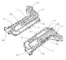
- FIG. 5 is an isometric exploded view of the housing and OMT/diplexer, showing mounting surfaces for the OMT and diplexer module within the receiver cavity of the housing.
- a transceiver with a cross-polar, co-polar receiver according to the invention is integrated into a single enclosure 10 .
- An OMT and diplexer module 12 may be mounted within the transceiver enclosure 10 without requiring specialized alignment procedures in multiple planes.
- an enclosure 10 has a feed flange 14 connection on a front end 16 and signal connection(s) 17 at the back end 18 .
- the enclosure has a top side transmitter cavity 20 and a bottom side receiver cavity 22 .
- a receiver cavity cover 24 and a transmitter cavity cover 26 enclose and environmentally seal the receiver cavity 22 and the transmitter cavity 20 , respectively.
- Heat sink(s) 28 may be arranged along the exterior sides of the enclosure 10 to assist with dissipation of heat generated by transceiver operation.
- the OMT and diplexer module 12 may be formed as a two piece assembly with grooves and sealing surfaces that cooperate to form a waveguide 30 and filter network functioning as an OMT and diplexer with cross-polar transmit reject filter (X-TRF) 32 , co-polar transmit reject filter (C-TRF) 34 , and co-polar receive reject filter (C-RRF) 36 .
- Signals are routed along a range of different waveguide 30 paths between a feed port 38 , co-polar transmission port 40 , co-polar reception port 42 and cross-polar reception port 44 .
- the X-TRF 32 , C-TRF 34 and C-RRF 36 filters are formed in the waveguide 30 sidewalls and or by application of a selected waveguide 30 cross section dimension relative to other waveguide 30 paths to remove undesired radio frequency signal components.
- Design and dimensional specifics of waveguide band-pass, high-pass and notch filters are well known in the art and as such are not discussed herein with greater detail.
- the floor of the receiver cavity 22 may be adapted to receive the OMT and diplexer module 12 .
- the OMT and diplexer module 12 is coupled to the feed flange 14 and is aligned with the enclosure 10 via a plurality of fasteners such as screws or like.
- the receiver printed circuit board 46 below and transmitter printed circuit board(s) 48 above are also thereby aligned to the other OMT and diplexer module 12 ports.
- a variety of snap on or interference fit connections may be applied.
- the OMT and diplexer module 12 may be alternatively located in the transmitter cavity 20 .
- the OMT and diplexer module 12 feed port 38 itself may form the feed flange 14 of the transceiver or alternatively the feed port 38 may be aligned directly with the feed flange 14 of the transceiver. Thereby avoiding the need for precision alignment between the OMT and diplexer module 12 to the enclosure 10 at the additional plane of the feed location.
- the OMT and diplexer module 12 cross-polar reception port 40 and co-polar reception port 42 may be arranged to exit the OMT and diplexer module 12 on a common side, while the co-polar transmission port 44 exits on an opposite side to couple with the receiver printed circuit board 46 and transmitter printed circuit board(s) 48 , respectively.
- the receiver printed circuit board 46 and the transmitter printed circuit board(s) 48 may be enclosed within the receiver cavity 22 and the transmitter cavity 20 by the receiver cavity cover 24 and the transmitter cavity cover 26 or other form of radio frequency and environmental screen. Positioning of the receiver printed circuit board 46 and the transmitter printed circuit board(s) 48 within separate reception and transmission cavities 22 , 20 of the enclosure 10 isolates the electrical circuitry for transmission and reception from each other. This helps to reduce cross coupling between different circuits on the receiver and transmitter printed circuit boards 46 , 48 .
- the planar two piece design of the OMT and diplexer module 12 enables use of cost efficient manufacturing methods such as die casting or injection molding.
- the X-TRF 32 , C-TRF 34 and C-RRF 36 are seamlessly incorporated into the OMT and diplexer module 12 , eliminating additional interconnections and potential signal degradation.
- the filters enable reception of signals in both orthogonal polarities while transmitting in one polarity.
- the OMT and diplexer module 12 may be fully tested prior to mounting in the enclosure 10 ; improving yield at transceiver final assembly and simplifying quality control procedures.
- the enclosure 10 may be cost effectively manufactured with a high level of precision via die casting or injection molding.
- Cavities, ports, fastener points, alignment posts and any heat sinks may be configured for die/mold separation without interfering overhanging edges.
- a plastic material with enhanced thermal conductivity properties may be used and or the surfaces of the resulting components may be coated with a conductive material to prevent radio frequency interference or leakage.
- metal inserts may be placed within the molds before injection of the plastic material to form integral heat sinks within the molded OMT and diplexer module 12 portion(s).
- a transceiver according to the invention significantly improves both electrical functionality and cost efficiency. Further, the modular design enables rapid application of further mechanical and or electrical circuit improvements that may arise. Because the number of required interconnections has been reduced, a transceiver according to the invention may be smaller and lighter than previous assemblies of similar function.
Abstract
Description
| 10 | |
| 12 | OMT and |
| 14 | |
| 16 | |
| 17 | |
| 18 | |
| 20 | |
| 22 | |
| 24 | |
| 26 | |
| 28 | |
| 30 | |
| 32 | cross-polar |
| 34 | co-polar |
| 36 | co-polar receive |
| 38 | |
| 40 | |
| 42 | |
| 44 | |
| 46 | receiver |
| 48 | transmitter printed circuit board |
Claims (20)
Priority Applications (1)
| Application Number | Priority Date | Filing Date | Title |
|---|---|---|---|
| US11/426,673 US7474173B2 (en) | 2006-06-27 | 2006-06-27 | Cross-polar and co-polar transceiver |
Applications Claiming Priority (1)
| Application Number | Priority Date | Filing Date | Title |
|---|---|---|---|
| US11/426,673 US7474173B2 (en) | 2006-06-27 | 2006-06-27 | Cross-polar and co-polar transceiver |
Publications (2)
| Publication Number | Publication Date |
|---|---|
| US20070296518A1 US20070296518A1 (en) | 2007-12-27 |
| US7474173B2 true US7474173B2 (en) | 2009-01-06 |
Family
ID=38873002
Family Applications (1)
| Application Number | Title | Priority Date | Filing Date |
|---|---|---|---|
| US11/426,673 Active 2027-03-15 US7474173B2 (en) | 2006-06-27 | 2006-06-27 | Cross-polar and co-polar transceiver |
Country Status (1)
| Country | Link |
|---|---|
| US (1) | US7474173B2 (en) |
Cited By (10)
| Publication number | Priority date | Publication date | Assignee | Title |
|---|---|---|---|---|
| US20100029199A1 (en) * | 2007-12-25 | 2010-02-04 | Microelectronics Technology Inc. | Integral high frequency communication apparatus |
| US20100102899A1 (en) * | 2008-10-27 | 2010-04-29 | Starling Advanced Communications Ltd. | Waveguide antenna front end |
| US20100292845A1 (en) * | 2009-05-13 | 2010-11-18 | United States Antenna Products, LLC | Enhanced azimuth antenna control |
| US20120092092A1 (en) * | 2007-12-25 | 2012-04-19 | Microelectronics Technology, Inc. | Integral high frequency communication apparatus |
| US20140070904A1 (en) * | 2012-09-07 | 2014-03-13 | Sean S. Cahill | Metalized molded plastic components for millimeter wave electronics and method for manufacture |
| US20140098722A1 (en) * | 2012-10-09 | 2014-04-10 | Wistron Neweb Corporation | Radio-frequency transceiver device in wireless communication system |
| US8698683B2 (en) | 2010-03-12 | 2014-04-15 | Andrew Llc | Dual polarized reflector antenna assembly |
| CN104617364A (en) * | 2015-01-21 | 2015-05-13 | 江苏贝孚德通讯科技股份有限公司 | Integrated waveguide radio frequency front-end component |
| CN109494479A (en) * | 2018-09-30 | 2019-03-19 | 安徽四创电子股份有限公司 | A kind of Ka waveband double-frequency dual polarization transmit-receive sharing feed |
| US10326189B2 (en) | 2017-04-25 | 2019-06-18 | Google Llc | Ortho-mode transducer and diplexer |
Families Citing this family (14)
| Publication number | Priority date | Publication date | Assignee | Title |
|---|---|---|---|---|
| GB0805310D0 (en) * | 2008-03-25 | 2008-04-30 | Asc Uk Signal Corp Ltd | Waveguide |
| US20100081373A1 (en) * | 2008-10-01 | 2010-04-01 | Lockheed Martin Corporation | Satellite feed assembly with integrated filters and test couplers |
| US8254851B2 (en) | 2008-11-11 | 2012-08-28 | Viasat, Inc. | Integrated orthomode transducer |
| WO2010056609A2 (en) * | 2008-11-11 | 2010-05-20 | Viasat, Inc. | Integrated orthomode transducer |
| CN101807930A (en) * | 2009-02-13 | 2010-08-18 | 华为技术有限公司 | Base station radio frequency duplexer, radio frequency module and radio frequency system |
| ES2362761B1 (en) * | 2009-04-28 | 2012-05-23 | Ferox Comunications, S.L. | MULTIPLEXOR OF CROSSED POLARIZATION. |
| US8981886B2 (en) | 2009-11-06 | 2015-03-17 | Viasat, Inc. | Electromechanical polarization switch |
| TW201126815A (en) * | 2009-11-06 | 2011-08-01 | Viasat Inc | Electromechanical polarization switch |
| US8779872B2 (en) | 2010-04-02 | 2014-07-15 | Hughes Network Systems, Llc | Method and apparatus for integrated waveguide transmit-receive isolation and filtering |
| US8594587B2 (en) | 2010-04-05 | 2013-11-26 | Hughes Network Systems, Llc | Method and apparatus for integrated waveguide transmit-receive isolation, filtering, and circular polarization |
| EP2609683B1 (en) | 2011-05-17 | 2018-03-21 | Huawei Technologies Co., Ltd. | Microwave module |
| EP2858168B1 (en) | 2012-07-04 | 2016-11-02 | Huawei Technologies Co., Ltd. | Microwave communication device and microwave communication system |
| CN104505564A (en) * | 2014-12-17 | 2015-04-08 | 科大智能(合肥)科技有限公司 | Dual polarization filter for microwave communication system ODU (Outdoor Unit) |
| US11936112B1 (en) * | 2022-05-05 | 2024-03-19 | Lockheed Martin Corporation | Aperture antenna structures with concurrent transmit and receive |
Citations (14)
| Publication number | Priority date | Publication date | Assignee | Title |
|---|---|---|---|---|
| US5162808A (en) * | 1990-12-18 | 1992-11-10 | Prodelin Corporation | Antenna feed with selectable relative polarization |
| US6009304A (en) | 1996-12-27 | 1999-12-28 | Sharp Kabushiki Kaisha | Two-output low-noise down converter circuit |
| JP2000252741A (en) | 1999-02-25 | 2000-09-14 | Nippon Hoso Kyokai <Nhk> | Multiple-satellite adaptive receiving antenna |
| US6373445B1 (en) | 1999-06-30 | 2002-04-16 | Masprodenkoh Kabushikikaisha | Converter for antenna to receive signals from two satellites |
| US6424817B1 (en) | 1998-02-04 | 2002-07-23 | California Amplifier, Inc. | Dual-polarity low-noise block downconverter systems and methods |
| US6507952B1 (en) | 1999-05-25 | 2003-01-14 | Rockwell Collins, Inc. | Passenger entertainment system providing live video/audio programming derived from satellite broadcasts |
| US6560850B2 (en) * | 2001-04-04 | 2003-05-13 | Hughes Electronics Corporation | Microwave waveguide assembly and method for making same |
| US6600897B1 (en) | 1999-01-27 | 2003-07-29 | Alps Electric Co., Ltd. | Satellite-broadcasting receiving converter with a plurality of output terminals |
| US6640084B2 (en) * | 2000-02-01 | 2003-10-28 | Krishna Pande | Complete outdoor radio unit for LMDS |
| US6677911B2 (en) * | 2002-01-30 | 2004-01-13 | Prodelin Corporation | Antenna feed assembly capable of configuring communication ports of an antenna at selected polarizations |
| US20040029549A1 (en) | 2002-08-09 | 2004-02-12 | Fikart Josef Ludvik | Downconverter for the combined reception of linear and circular polarization signals from collocated satellites |
| US20040077307A1 (en) | 2002-10-17 | 2004-04-22 | Hiroshi Atarashi | Satellite broadcast receiver apparatus intended to reduce power consumption |
| WO2005109703A1 (en) | 2004-05-11 | 2005-11-17 | Invacom Ltd | Means for receiving data via satellite using at least two polarisations |
| WO2006040538A2 (en) | 2004-10-11 | 2006-04-20 | Invacom Ltd | Apparatus for selected provision of linear and/or circular polarity signals |
-
2006
- 2006-06-27 US US11/426,673 patent/US7474173B2/en active Active
Patent Citations (14)
| Publication number | Priority date | Publication date | Assignee | Title |
|---|---|---|---|---|
| US5162808A (en) * | 1990-12-18 | 1992-11-10 | Prodelin Corporation | Antenna feed with selectable relative polarization |
| US6009304A (en) | 1996-12-27 | 1999-12-28 | Sharp Kabushiki Kaisha | Two-output low-noise down converter circuit |
| US6424817B1 (en) | 1998-02-04 | 2002-07-23 | California Amplifier, Inc. | Dual-polarity low-noise block downconverter systems and methods |
| US6600897B1 (en) | 1999-01-27 | 2003-07-29 | Alps Electric Co., Ltd. | Satellite-broadcasting receiving converter with a plurality of output terminals |
| JP2000252741A (en) | 1999-02-25 | 2000-09-14 | Nippon Hoso Kyokai <Nhk> | Multiple-satellite adaptive receiving antenna |
| US6507952B1 (en) | 1999-05-25 | 2003-01-14 | Rockwell Collins, Inc. | Passenger entertainment system providing live video/audio programming derived from satellite broadcasts |
| US6373445B1 (en) | 1999-06-30 | 2002-04-16 | Masprodenkoh Kabushikikaisha | Converter for antenna to receive signals from two satellites |
| US6640084B2 (en) * | 2000-02-01 | 2003-10-28 | Krishna Pande | Complete outdoor radio unit for LMDS |
| US6560850B2 (en) * | 2001-04-04 | 2003-05-13 | Hughes Electronics Corporation | Microwave waveguide assembly and method for making same |
| US6677911B2 (en) * | 2002-01-30 | 2004-01-13 | Prodelin Corporation | Antenna feed assembly capable of configuring communication ports of an antenna at selected polarizations |
| US20040029549A1 (en) | 2002-08-09 | 2004-02-12 | Fikart Josef Ludvik | Downconverter for the combined reception of linear and circular polarization signals from collocated satellites |
| US20040077307A1 (en) | 2002-10-17 | 2004-04-22 | Hiroshi Atarashi | Satellite broadcast receiver apparatus intended to reduce power consumption |
| WO2005109703A1 (en) | 2004-05-11 | 2005-11-17 | Invacom Ltd | Means for receiving data via satellite using at least two polarisations |
| WO2006040538A2 (en) | 2004-10-11 | 2006-04-20 | Invacom Ltd | Apparatus for selected provision of linear and/or circular polarity signals |
Cited By (19)
| Publication number | Priority date | Publication date | Assignee | Title |
|---|---|---|---|---|
| US8106843B2 (en) * | 2007-12-25 | 2012-01-31 | Microelectronics Technology, Inc. | Integral high frequency communication apparatus |
| US20120092092A1 (en) * | 2007-12-25 | 2012-04-19 | Microelectronics Technology, Inc. | Integral high frequency communication apparatus |
| US20100029199A1 (en) * | 2007-12-25 | 2010-02-04 | Microelectronics Technology Inc. | Integral high frequency communication apparatus |
| US9024835B2 (en) * | 2007-12-25 | 2015-05-05 | Microelectronics Technology, Inc. | Integral high frequency communication apparatus |
| US20100102899A1 (en) * | 2008-10-27 | 2010-04-29 | Starling Advanced Communications Ltd. | Waveguide antenna front end |
| US7821355B2 (en) * | 2008-10-27 | 2010-10-26 | Starling Advanced Communications Ltd. | Waveguide antenna front end |
| USRE46038E1 (en) | 2009-05-13 | 2016-06-21 | United States Antenna Products, LLC | Enhanced azimuth antenna control |
| US20100292845A1 (en) * | 2009-05-13 | 2010-11-18 | United States Antenna Products, LLC | Enhanced azimuth antenna control |
| US8423201B2 (en) | 2009-05-13 | 2013-04-16 | United States Antenna Products, LLC | Enhanced azimuth antenna control |
| US8698683B2 (en) | 2010-03-12 | 2014-04-15 | Andrew Llc | Dual polarized reflector antenna assembly |
| US20140070904A1 (en) * | 2012-09-07 | 2014-03-13 | Sean S. Cahill | Metalized molded plastic components for millimeter wave electronics and method for manufacture |
| US9960468B2 (en) * | 2012-09-07 | 2018-05-01 | Remec Broadband Wireless Networks, Llc | Metalized molded plastic components for millimeter wave electronics and method for manufacture |
| US20140098722A1 (en) * | 2012-10-09 | 2014-04-10 | Wistron Neweb Corporation | Radio-frequency transceiver device in wireless communication system |
| US8988163B2 (en) * | 2012-10-09 | 2015-03-24 | Wistron Neweb Corporation | Radio-frequency transceiver device in wireless communication system |
| CN104617364A (en) * | 2015-01-21 | 2015-05-13 | 江苏贝孚德通讯科技股份有限公司 | Integrated waveguide radio frequency front-end component |
| CN104617364B (en) * | 2015-01-21 | 2017-10-03 | 江苏贝孚德通讯科技股份有限公司 | A kind of integrated waveguide radio-frequency front-end component |
| US10326189B2 (en) | 2017-04-25 | 2019-06-18 | Google Llc | Ortho-mode transducer and diplexer |
| CN109494479A (en) * | 2018-09-30 | 2019-03-19 | 安徽四创电子股份有限公司 | A kind of Ka waveband double-frequency dual polarization transmit-receive sharing feed |
| CN109494479B (en) * | 2018-09-30 | 2020-11-17 | 安徽四创电子股份有限公司 | Ka-band dual-frequency dual-polarization receiving and transmitting common feed source |
Also Published As
| Publication number | Publication date |
|---|---|
| US20070296518A1 (en) | 2007-12-27 |
Similar Documents
| Publication | Publication Date | Title |
|---|---|---|
| US7474173B2 (en) | Cross-polar and co-polar transceiver | |
| EP2221910B1 (en) | Base station RF duplexer, RF module, and RF system field | |
| CN109038054B (en) | Pluggable module comprising a cooling channel with heat transfer fins | |
| US6369924B1 (en) | Optical transceiver with enhanced shielding and related methods | |
| EP1677382B1 (en) | Waveguide - printed wiring board (PWB) interconnection | |
| EP1772928A1 (en) | Integrated satellite communications outdoor unit | |
| EP3306739B1 (en) | Cavity filter | |
| KR101508916B1 (en) | Printed circuit board and diplexer circuit | |
| US20120268329A1 (en) | Integrated Waveguide Transceiver | |
| EP1544938A1 (en) | Multiple cavity filter | |
| EP4087057A1 (en) | Array antenna | |
| EP1691446A1 (en) | Multiple beam feed assembly | |
| EP1544940A1 (en) | Tower mounted amplifier filter and manufacturing method thereof | |
| CA3158424A1 (en) | Differential pair module, connector, communications device, and shielding assembly | |
| WO2003023987A9 (en) | Transceiver assembly | |
| CN110323564A (en) | A kind of active antenna element and antenna element for base station | |
| EP2609683B1 (en) | Microwave module | |
| CN215184475U (en) | Ring filter assembly | |
| CN113097674A (en) | Ring filter assembly | |
| US6404300B2 (en) | Microwave module for separating high frequency transmission signals and high frequency reception signals on the basis of their frequencies | |
| EP4191783A1 (en) | Antenna device | |
| WO2024021591A1 (en) | Antenna and communication device | |
| CN110311208B (en) | Wireless communication equipment integrating horn antenna on PCB, production method and application | |
| US20230361442A1 (en) | Filter unit, antenna filter unit and radio unit | |
| CN220419560U (en) | Receiving and transmitting assembly |
Legal Events
| Date | Code | Title | Description |
|---|---|---|---|
| AS | Assignment |
Owner name: ANDREW CORPORATION, ILLINOIS Free format text: ASSIGNMENT OF ASSIGNORS INTEREST;ASSIGNORS:AVRAMIS, MR. EVANGELOS;HOPKINSON, MR. PETER;ROULSTON, MR. DAVID JOHN;AND OTHERS;REEL/FRAME:017850/0296 Effective date: 20060627 |
|
| AS | Assignment |
Owner name: ASC SIGNAL CORPORATION, NORTH CAROLINA Free format text: ASSIGNMENT OF ASSIGNORS INTEREST;ASSIGNOR:ANDREW CORPORATION;REEL/FRAME:020886/0407 Effective date: 20080131 |
|
| AS | Assignment |
Owner name: PNC BANK, NATIONAL ASSOCIATION, PENNSYLVANIA Free format text: SECURITY AGREEMENT;ASSIGNOR:ASC SIGNAL CORPORATION;REEL/FRAME:021018/0816 Effective date: 20080422 |
|
| STCF | Information on status: patent grant |
Free format text: PATENTED CASE |
|
| REMI | Maintenance fee reminder mailed | ||
| FPAY | Fee payment |
Year of fee payment: 4 |
|
| SULP | Surcharge for late payment | ||
| AS | Assignment |
Owner name: ASC SIGNAL CORPORATION, NORTH CAROLINA Free format text: RELEASE BY SECURED PARTY;ASSIGNOR:PNC BANK, NATIONAL ASSOCIATION;REEL/FRAME:030320/0276 Effective date: 20090529 Owner name: RAVEN NC, LLC, NORTH CAROLINA Free format text: ASSIGNMENT OF ASSIGNORS INTEREST;ASSIGNOR:ASC SIGNAL CORPORATION;REEL/FRAME:030320/0460 Effective date: 20090529 Owner name: RAVEN ANTENNA SYSTEMS INC., NORTH CAROLINA Free format text: CHANGE OF NAME;ASSIGNOR:RAVEN NC, LLC;REEL/FRAME:030320/0685 Effective date: 20100305 |
|
| AS | Assignment |
Owner name: SATCOM TECHNOLOGY B.V., NETHERLANDS Free format text: ASSIGNMENT OF ASSIGNORS INTEREST;ASSIGNORS:RAVEN ANTENNA SYSTEMS INC.;SATELLITE ACQUISITION CORPORATION;RAVEN UK HOLDINGS LIMITED;AND OTHERS;REEL/FRAME:030874/0003 Effective date: 20130517 |
|
| FPAY | Fee payment |
Year of fee payment: 8 |
|
| AS | Assignment |
Owner name: SKYWARE TECHNOLOGIES (UK) LTD., UNITED KINGDOM Free format text: ASSIGNMENT OF ASSIGNORS INTEREST;ASSIGNOR:SATCOM TECHNOLOGY B.V.;REEL/FRAME:041281/0602 Effective date: 20170101 |
|
| AS | Assignment |
Owner name: GLOBAL SKYWARE LIMITED, UNITED KINGDOM Free format text: CHANGE OF NAME;ASSIGNOR:GI PROVISION LIMITED;REEL/FRAME:052079/0360 Effective date: 20180906 Owner name: GI PROVISION LIMITED, UNITED KINGDOM Free format text: ASSIGNMENT OF ASSIGNORS INTEREST;ASSIGNORS:SKYWARE TECHNOLOGIES (IRELAND) LTD.;SKYWARE TECHNOLOGIES (UK) LTD.;SKYWARE RADIO SYSTEMS GMBH, D/B/A SKYWARE TECHNOLOGIES;AND OTHERS;REEL/FRAME:052144/0872 Effective date: 20180904 |
|
| MAFP | Maintenance fee payment |
Free format text: PAYMENT OF MAINTENANCE FEE, 12TH YR, SMALL ENTITY (ORIGINAL EVENT CODE: M2553); ENTITY STATUS OF PATENT OWNER: SMALL ENTITY Year of fee payment: 12 |