US7475741B2 - Method and system for precise drilling guidance of twin wells - Google Patents
Method and system for precise drilling guidance of twin wells Download PDFInfo
- Publication number
- US7475741B2 US7475741B2 US10/998,781 US99878104A US7475741B2 US 7475741 B2 US7475741 B2 US 7475741B2 US 99878104 A US99878104 A US 99878104A US 7475741 B2 US7475741 B2 US 7475741B2
- Authority
- US
- United States
- Prior art keywords
- well
- drilling
- current
- path
- electromagnetic field
- Prior art date
- Legal status (The legal status is an assumption and is not a legal conclusion. Google has not performed a legal analysis and makes no representation as to the accuracy of the status listed.)
- Expired - Fee Related, expires
Links
Images


Classifications
-
- E—FIXED CONSTRUCTIONS
- E21—EARTH DRILLING; MINING
- E21B—EARTH DRILLING, e.g. DEEP DRILLING; OBTAINING OIL, GAS, WATER, SOLUBLE OR MELTABLE MATERIALS OR A SLURRY OF MINERALS FROM WELLS
- E21B7/00—Special methods or apparatus for drilling
- E21B7/04—Directional drilling
-
- E—FIXED CONSTRUCTIONS
- E21—EARTH DRILLING; MINING
- E21B—EARTH DRILLING, e.g. DEEP DRILLING; OBTAINING OIL, GAS, WATER, SOLUBLE OR MELTABLE MATERIALS OR A SLURRY OF MINERALS FROM WELLS
- E21B47/00—Survey of boreholes or wells
- E21B47/02—Determining slope or direction
- E21B47/022—Determining slope or direction of the borehole, e.g. using geomagnetism
- E21B47/0228—Determining slope or direction of the borehole, e.g. using geomagnetism using electromagnetic energy or detectors therefor
Definitions
- the present invention relates to the field of well drilling guidance and, in particular, to guidance systems that use electromagnetic fields associated with an existing well casing to steer the drilling of a second well proximate to the first.
- a pair of horizontal wells may be drilled to extract oil from a deposit of heavy oil or tar.
- an upper well may inject steam into a subterranean deposit of heavy oil or tar while the lower well collects liquefied oil from the deposit.
- the pair of wells are to be positioned within a few meters of each other along the length of the lateral such that the oil liquefied by the steam from the first well is collected by the second well.
- drilling path of the second well may be specified to be within a few meters, e.g., 4 to 10 meters, of the first well, but held to within a tolerance, for example, of plus or minus 1 meter. Drilling guidance methods and system are needed to ensure that the drilling path of the second well remains properly aligned with the first well along the entire drilling path of the second well.
- Surveying the drilling path at successive points along the path is a conventional drilling guidance method.
- a difficulty with surveying is that a cumulative error arises in the surveyed well path because small errors made at each successive survey point along the well path are introduced into the survey calculation made at subsequent survey points. The cumulative effect of these small errors may eventually cause the drilling path of the second well to drift outside the specified desired ranges of distance or direction relative to the first well.
- U.S. Pat. Nos. 6,530,154; 5,435,069; 5,230,387; 5,512,830 and 3,725,777, and Published US Patent Application 2002/0112,856 disclose various drilling guidance methods and systems to provide drilling path guidance and to compensate for the cumulative effect of conventional survey errors. These known techniques include sensing a magnetic field generated by the magnetic properties of a well casing or a magnetic probe introduced into the well. These methods and systems may require the use a second rig or other device in the first well to push or pump down a magnetic signal source device. The magnetic fields from such a source are subject to magnetic attenuation and distortion by the first well casing, and may also generate a relatively weak magnetic field that is difficult to sense from the desired second well drilling path. In view of these difficulties, there remains a long felt need for a method and system to guide the trajectory of a second well such that is aligned with an existing well.
- a system and method have been developed to precisely guide the drilling trajectory of a second well in a manner that ensures that the second well is properly aligned with a first well.
- a metallic casing in the first well conducts an alternating current that generates an alternating magnetic field in the earth surrounding the first well. This magnetic field is substantially more predictable in magnitude than would be a magnetic field due solely to the static magnetic properties of the first well.
- the intended drilling trajectory of the second well is within the measurable magnetic field generated by the current in the first well.
- a magnetic detector is included within the drilling assembly used for boring the second hole. The magnetic detector senses the magnetic field generated by the current in the first well. Values measured of strength and direction of the magnetic field are used to align the trajectory of the drilling assembly drilling the hole for the second well.
- the system may be used to guide a second horizontal well being drilled near a first horizontal well to enhance oil production from subterranean reservoirs of heavy oil or tar sands.
- the two parallel wells are to be positioned one above the other and separated by a certain distance, e.g., within the range of 4 to 10 meters, through a horizontal section of a heavy oil or tar deposit.
- the method guides a drilling path so that the second horizontal well is a consistent and short distance from the first well by: (1) causing a known electrical current to flow in the metallic casing or liner (collectively “casing”) of the first well to produce a continuous magnetic field in the region about the first well, and (2) using magnetic field sensing instruments in the second well while drilling to measure and calculate accurate distance and direction information relative to the first well so that the driller can correct the trajectory of the second well and position the second well in the desired relationship to the first well.
- casing metallic casing or liner
- the invention is a method to guide a drilling path of a second well in proximity to a first well including: applying a time-varying electrical current to a conductive casing of the first well; from the drilling path of the second well, sensing an electromagnetic field generated by the current in the first well, and guiding the drilling path trajectory of the second well using the sensed electromagnetic field.
- the inventive method may be a method to guide the drilling path of a second well in proximity to a first well comprising: drilling a third well towards a distal section of the first well and establishing a conductive path along the third well to the distal section of the first well; forming an electrical circuit comprising an electrical generator, a conductive casing of the first well and the conductive path along the third well, wherein said generator applies a time-varying electrical current to the circuit; from the drilling path of the second well, sensing an electromagnetic field generated by the current in the first well, and guiding the drilling path of the second well using the sensed electromagnetic field.
- the invention may also be embodied as a drilling guidance system for guiding a drilling path of a second well in proximity to a first well, said system comprising: a first conductive path extending a length of the first well; a generator of electrical current connected to opposite ends of the first well to apply current to the first conductive path, and a magnetic field sensor in the drilling path of the second well arranged to detect a field strength and direction of an electromagnetic field generated by the current applied to the first conductive path.
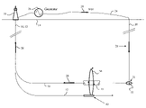
- FIG. 1 is a schematic illustration of an elevation of a well plan for drilling twin horizontal wells.
- FIG. 2 is a schematic map of locations for twin horizontal boreholes and an acceptable region for the trajectory of the second well.
- FIG. 3 is a schematic diagram of an exemplary magnetic sensor array.
- FIG. 4 is a side view of an exemplary electrode in the third well that provides electrical contact to the first well.
- FIG. 1 schematically illustrates a typical well plan for drilling twin horizontal wells 10 , 12 .
- the wells On the ground 14 the wells may be drilled from one or two drilling platforms 16 , more likely two. After initially being drilled substantially vertically, the wells are drilled horizontally into a deposit of, for example, heavy oil or tar.
- the first well 12 is drilled and cased before drilling commences on the second horizontal well 10 .
- the casing or slotted liner are metallic and will conduct electricity.
- the horizontal portion of the first well may be above the second well by several meters, e.g., 4 to 10 meters.
- a directional survey is made of the first well to map the well and facilitate planning a surface location for a small, vertical borehole 20 which is a third well.
- This small borehole will nearly intersect 21 the first well at the distal termination end of the first well.
- the small hole with a temporary casing installed, preferably of a non-conductive material such as PVC installed, need only to be large enough to accommodate a special electrode 22 to be lowered to the bottom and near to the first casing.
- the small vertical hole may be similar in size to a water well and may extend a few meters deeper that the first well.
- a suitable conductive fluid may be pumped into the well 20 .
- the electrode 22 is lowered into the vertical hole to provide a current path through the small well.
- the electrode 22 electrically connects the casing or liner 18 of the first well to a conductive path, e.g. a wire, in the small bore hole 20 .
- An above ground conductive path e.g., wires 24 , connects the surface ends of the third well 20 and the casing or liner 18 of the first well 10 to an alternating-current (AC) electrical generator 26 .
- the electrical power from the generator drives a current 28 that flows through the wire 24 , third well 20 , electrode 22 , casing or liner of the first well 18 and to the generator.
- the alternating-current 28 induces an electromagnetic field 30 in the earth surrounding the casing 18 of the first well.
- the characteristics of an electromagnetic field from an AC conductive path are well-known.
- the strength of the electromagnetic field 30 is proportional to the alternating current applied by the generator.
- the magnitude of current in the casing may be measured with precision by an amp meter, for example. Because the strength of the magnetic fields is proportional to the current, there is a well-defined relationship between the current, measured magnetic field strength at the new well and the distance between the new well and casing of the first well.
- the strength and direction of the magnetic field are indicative of the distance and direction to the casing of the first well.
- FIG. 2 is a schematic view of the first and second wells at a cross-sectional plane along the vertical sections through the wells.
- the electromagnetic field 30 emanates from the casing 18 of the fist well 10 and into the surrounding earth.
- the second well 12 is shown as the lower well, however the position of the first and second well may be reversed depending on the drilling application.
- a magnetic sensor assembly 40 in the second well senses the magnetic field.
- the acceptable drilling path of the second well is defined by an acceptable zone 32 that is shown in cross-section in FIG. 2 .
- the acceptable zone 32 may be a region that is usually centered in the range of 4 to 10 meters below the first well.
- the zone 32 may have a short axis along a radius drawn from the upper well and a long axis perpendicular to a vertical plane through the upper well.
- the dimensions of the acceptable zone may be one meter along the short axis and two meters along the long axis of the zone.
- the shape and dimensions of the acceptable zone are known for each drilling application, but may differ depending on the application.
- the drilling trajectory for the second well should remain in the acceptable zone 32 for the entire length of the horizontal portion of the two wells.
- the drilling guidance system which includes the sensor assembly 40 , is used to maintain the drilling trajectory of the second well within the acceptable zone. Whether the drilling trajectory of the second well 12 is within the acceptable zone 32 is determined based on the direction and strength of the electromagnetic field 30 along the second well path as sensed by the magnetic sensor assembly 40 . Measurements of the field intensity and field direction by the sensor assembly 40 , in the second well provide information sufficient to determine the direction to the first well and the distance between the two wells. This information is provided to the driller in a convenient form so that he can take appropriate action to maintain the trajectories of the two wells in the proper relationship.
- the sensor assembly 40 is incorporated into the down hole probe of a wireline steering tool or MWD system for drilling the second well 12 . The sensor assembly thus guides the drilling of the second well for directional control of the drill path trajectory.
- the magnetic field (B) produced by a long straight conductor, such as the well casing, is proportional to the current (I) in the conductor and inversely proportional to the perpendicular distance (r) from the conductor.
- u t is the magnetic permeability of the region surrounding the conductor and is constant.
- the distance (r) of the second bore hole from the casing of the first well can thus be determined based on the measurement of the current (I) in the casing and the magnetic field strength (B) at the second bore hole.
- FIG. 3 is a schematic diagram of a component-type magnetic sensor assembly 40 (shown in a cut-away view) having the ability to discriminate field direction.
- Component-type magnetic sensors e.g., magnetometers and accelerometers, are directional and survey sensors conventionally included measurement-while-drilling (MWD) sensors.
- MWD measurement-while-drilling
- the sensor assembly 40 moves through the second bore hole typically a few yards behind the drill bit and associated drilling equipment.
- the sensor assembly 40 collects data used to determine the location of the second bore hole. This information issues to guide the drill bit along a desired drilling trajectory of the second well.
- the sensor assembly 40 also includes standard orientation sensors (three orthogonal magnetometers 48 and three orthogonal accelerometers 51 , and three orthogonal alternating-field magnetic sensors 44 , 46 , 52 for detection of the electro magnetic field about the first (reference) well.
- the magnetic sensors have a component response pattern and are most sensitive to alternating magnetic field intensity corresponding to the frequency of the alternating current source. These sensors are mounted in a fixed relative orientation in the housing for the sensor assembly.
- a pair of radial component-magnetic sensors 44 and 46 are arranged in the probe assembly 40 such that their magnetically sensitive axes are mutually orthogonal.
- Each component sensor 44 , 46 measures the relative magnetic field (B) strengths at the second well.
- the sensors will each detect different field strengths due to their orthogonal orientations.
- the direction on the field (B) may be determined by the inverse tangent (tan ⁇ 1 ) of the ratio of the field strength sensed by the radial sensors 44 , 46 .
- the frame of reference for the radial sensors 44 , 46 is the earth's gravity and magnetic north, determined by the magnetic sensors 48 and the gravity sensors.
- the direction to the conductor of current is calculated by adding 90 degrees to the direction of the field at the point of measurement.
- the direction from the sensors to the first well and the perpendicular distance between the sensors and the first well provides sufficient information to guide the trajectory of the second well in the acceptable zone 32 .
- FIG. 4 is a schematic illustration of an exemplary electrode 22 lowered into the small vertical hole 20 to the zone where the conductive fluid has been introduced.
- the electrode 22 includes metallic springs 50 e.g., an expandable mesh, that expand to contact the walls of the open borehole of the well 20 .
- the spring elements 50 may be retracted to a size which slides through the temporary casing 53 of the vertical well 20 .
- the temporary casing insures that the material around the borehole does not slough into the hole.
- the electrode 22 is positioned near the first casing 18 at the intersection 21 of the two wells.
- a conductive fluid in the third well 20 seeps into the earth 56 surrounding the intersection 21 between wells.
- the conductive fluid enhances the electrical connectivity between the first casing and third well.
- the electrode is connected to the insulated conductor wire 54 that extends through the well 20 and to the surface.
- the wire 54 is connected via wire 24 to the return side of the generator.
Abstract
Description
B=u t I/(2Πr)
Claims (10)
Priority Applications (6)
| Application Number | Priority Date | Filing Date | Title |
|---|---|---|---|
| US10/998,781 US7475741B2 (en) | 2004-11-30 | 2004-11-30 | Method and system for precise drilling guidance of twin wells |
| CA2527271A CA2527271C (en) | 2004-11-30 | 2005-11-17 | Method for precise drilling guidance of twin wells |
| RU2005137146/03A RU2386810C2 (en) | 2004-11-30 | 2005-11-29 | Method and system for exact direction of drilling of double wells |
| CN2005101285131A CN1782320B (en) | 2004-11-30 | 2005-11-30 | Method and system for precise drilling guidance of twin wells |
| US12/352,288 US8418782B2 (en) | 2004-11-30 | 2009-01-12 | Method and system for precise drilling guidance of twin wells |
| US12/352,421 US20090120691A1 (en) | 2004-11-30 | 2009-01-12 | Systems and methods for guiding the drilling of a horizontal well |
Applications Claiming Priority (1)
| Application Number | Priority Date | Filing Date | Title |
|---|---|---|---|
| US10/998,781 US7475741B2 (en) | 2004-11-30 | 2004-11-30 | Method and system for precise drilling guidance of twin wells |
Related Child Applications (2)
| Application Number | Title | Priority Date | Filing Date |
|---|---|---|---|
| US12/352,288 Continuation-In-Part US8418782B2 (en) | 2004-11-30 | 2009-01-12 | Method and system for precise drilling guidance of twin wells |
| US12/352,421 Continuation-In-Part US20090120691A1 (en) | 2004-11-30 | 2009-01-12 | Systems and methods for guiding the drilling of a horizontal well |
Publications (2)
| Publication Number | Publication Date |
|---|---|
| US20060113112A1 US20060113112A1 (en) | 2006-06-01 |
| US7475741B2 true US7475741B2 (en) | 2009-01-13 |
Family
ID=36565949
Family Applications (1)
| Application Number | Title | Priority Date | Filing Date |
|---|---|---|---|
| US10/998,781 Expired - Fee Related US7475741B2 (en) | 2004-11-30 | 2004-11-30 | Method and system for precise drilling guidance of twin wells |
Country Status (4)
| Country | Link |
|---|---|
| US (1) | US7475741B2 (en) |
| CN (1) | CN1782320B (en) |
| CA (1) | CA2527271C (en) |
| RU (1) | RU2386810C2 (en) |
Cited By (9)
| Publication number | Priority date | Publication date | Assignee | Title |
|---|---|---|---|---|
| US20090178850A1 (en) * | 2004-11-30 | 2009-07-16 | General Electric Company | Method and system for precise drilling guidance of twin wells |
| US20110139507A1 (en) * | 2009-12-10 | 2011-06-16 | Baker Hughes Incorporated | Method and Apparatus for Borehole Positioning |
| US20110298462A1 (en) * | 2008-11-20 | 2011-12-08 | Brian Clark | Method and apparatus for calibrating and correcting for coherent noise in casing detection |
| WO2012067611A1 (en) * | 2010-11-17 | 2012-05-24 | Halliburton Energy Services Inc. | Apparatus and method for drilling a well |
| US20120205159A1 (en) * | 2009-07-06 | 2012-08-16 | Petroleo Brasileiro S.A. - Petrobras | Receiving lateral wellbore and method for implanting same |
| US9354349B2 (en) | 2011-11-18 | 2016-05-31 | Halliburton Energy Services, Inc. | Systems and methodology for detecting a conductive structure |
| US9625605B2 (en) | 2012-12-21 | 2017-04-18 | Halliburton Energy Services, Inc. | Systems and methods for performing ranging measurements using third well referencing |
| US10775528B2 (en) | 2013-03-11 | 2020-09-15 | Halliburton Energy Services, Inc. | Downhole ranging from multiple boreholes |
| US11125472B2 (en) | 2018-05-10 | 2021-09-21 | Eavor Technologies Inc. | Fluid for use in power production environments |
Families Citing this family (35)
| Publication number | Priority date | Publication date | Assignee | Title |
|---|---|---|---|---|
| US8307915B2 (en) | 2008-04-10 | 2012-11-13 | Schlumberger Technology Corporation | System and method for drilling multilateral wells using magnetic ranging while drilling |
| US8827005B2 (en) * | 2008-04-17 | 2014-09-09 | Schlumberger Technology Corporation | Method for drilling wells in close relationship using magnetic ranging while drilling |
| US8056343B2 (en) * | 2008-10-01 | 2011-11-15 | General Electric Company | Off center combustor liner |
| AU2010200041B2 (en) * | 2009-01-12 | 2016-09-22 | General Electric Company | Method and system for precise drilling guidance of twin wells |
| CA2765306C (en) | 2009-06-17 | 2013-09-17 | Halliburton Energy Services, Inc. | Drilling collision avoidance apparatus, methods, and systems |
| EP2317069A1 (en) * | 2009-10-30 | 2011-05-04 | Welltec A/S | Magnetic ranging system for controlling a drilling process |
| CN103089159A (en) * | 2011-11-08 | 2013-05-08 | 南通永大管业股份有限公司 | Intelligent drilling rod with chip and intelligent drilling rod data transmission device |
| CN102536206B (en) * | 2011-12-30 | 2014-05-28 | 中北大学 | Method for drilling azimuth measurement based on magnetic inclinometer in magnetic casing |
| CN103485755A (en) * | 2012-06-13 | 2014-01-01 | 南风化工集团股份有限公司 | Drilling process of anhydrous sodium sulfate mine well |
| CA2890330C (en) * | 2012-12-07 | 2019-12-03 | Halliburton Energy Services, Inc. | Drilling parallel wells for sagd and relief |
| AU2013354973B2 (en) * | 2012-12-07 | 2016-11-17 | Halliburton Energy Services, Inc. | Gradient-based single well SAGD ranging system |
| CN103470237B (en) * | 2013-09-06 | 2016-04-06 | 兴和鹏能源技术(北京)股份有限公司 | Unconventional oppositely to the method for wearing and rotating signal omniselector |
| US10520628B2 (en) * | 2013-09-30 | 2019-12-31 | Halliburton Energy Services, Inc. | Downhole gradiometric ranging for T-intersection and well avoidance utilizing transmitters and receivers having magnetic dipoles |
| CA2925276C (en) * | 2013-12-05 | 2018-01-02 | Halliburton Energy Services, Inc. | Downhole triaxial electromagnetic ranging |
| WO2015099790A1 (en) * | 2013-12-27 | 2015-07-02 | Halliburton Energy Services, Inc. | Drilling collision avoidance apparatus, methods, and systems |
| WO2016025241A1 (en) | 2014-08-11 | 2016-02-18 | Halliburton Energy Services, Inc. | Well ranging apparatus, systems, and methods |
| US10041345B2 (en) * | 2014-10-01 | 2018-08-07 | Applied Technologies Associates, Inc. | Well completion with single wire guidance system |
| CA2959868C (en) | 2014-10-17 | 2018-11-27 | Applied Technologies Associates, Inc. | Active magnetic azimuthal toolface for vertical borehole kickoff in magnetically perturbed environments |
| US10760406B2 (en) * | 2014-12-30 | 2020-09-01 | Halliburton Energy Services, Inc. | Locating multiple wellbores |
| WO2016108865A1 (en) * | 2014-12-31 | 2016-07-07 | Halliburton Energy Services, Inc. | Magnetic sensor rotation and orientation about drill |
| RU2667534C1 (en) * | 2014-12-31 | 2018-09-21 | Халлибертон Энерджи Сервисез, Инк. | Single-wire guide system for determining distances using unbalanced magnetic fields |
| EP3274551A4 (en) * | 2015-03-25 | 2018-11-21 | Halliburton Energy Services, Inc. | Surface excitation ranging methods and systems employing a customized grounding arrangement |
| US20160362937A1 (en) * | 2015-06-15 | 2016-12-15 | Schlumberger Technology Corporation | Formation analysis and drill steering using lateral wellbores |
| US9816838B2 (en) * | 2015-08-24 | 2017-11-14 | Infineon Technologies Ag | Magnetoresistive angle sensor with linear sensor elements |
| WO2017105500A1 (en) | 2015-12-18 | 2017-06-22 | Halliburton Energy Services, Inc. | Systems and methods to calibrate individual component measurement |
| RU2755609C2 (en) * | 2016-12-30 | 2021-09-17 | Эволюшн Инжиниринг Инк. | System and method for telemetry of data between neighboring wells |
| CN109209353B (en) * | 2017-07-03 | 2022-06-03 | 中国石油天然气股份有限公司 | Device and method for determining distance and direction between wells in drilling process of oil and gas wells |
| CN108166972A (en) * | 2017-12-22 | 2018-06-15 | 西安石油大学 | A kind of magnetic survey for controlling parallel well drilling is away from system and method |
| CN108442915B (en) * | 2018-03-29 | 2024-01-26 | 中国石油大学(北京) | Method and device for determining oil well distance |
| CN109667550B (en) * | 2018-12-28 | 2021-07-23 | 中国石油大学(华东) | Active distance measurement system and method for cluster well collision prevention |
| CN112253084B (en) * | 2020-09-15 | 2024-02-27 | 中石化石油工程技术服务有限公司 | Underground double-probe magnetic measurement device and method |
| CN112983275B (en) * | 2021-03-09 | 2023-01-24 | 中国石油化工股份有限公司 | Shale gas horizontal well continuous fluctuation type reservoir horizontal section geosteering trajectory control method |
| CN115341889B (en) * | 2022-05-20 | 2023-03-24 | 中国石油天然气集团有限公司 | Underground discharging operation system with externally-coated bearing cable electrode |
| CN117027764B (en) * | 2022-05-20 | 2024-02-09 | 中国石油天然气集团有限公司 | Drilling positioning device, method and system |
| CN115653498B (en) * | 2022-10-17 | 2023-11-07 | 中交第三公路工程局有限公司 | Construction method of horizontal directional drilling drag pipe |
Citations (22)
| Publication number | Priority date | Publication date | Assignee | Title |
|---|---|---|---|---|
| US3725777A (en) | 1971-06-07 | 1973-04-03 | Shell Oil Co | Method for determining distance and direction to a cased borehole using measurements made in an adjacent borehole |
| US4072200A (en) | 1976-05-12 | 1978-02-07 | Morris Fred J | Surveying of subterranean magnetic bodies from an adjacent off-vertical borehole |
| US4458767A (en) * | 1982-09-28 | 1984-07-10 | Mobil Oil Corporation | Method for directionally drilling a first well to intersect a second well |
| US4465140A (en) | 1982-09-28 | 1984-08-14 | Mobil Oil Corporation | Method for the magnetization of well casing |
| US4593770A (en) * | 1984-11-06 | 1986-06-10 | Mobil Oil Corporation | Method for preventing the drilling of a new well into one of a plurality of production wells |
| US5064006A (en) | 1988-10-28 | 1991-11-12 | Magrange, Inc | Downhole combination tool |
| US5155916A (en) | 1991-03-21 | 1992-10-20 | Scientific Drilling International | Error reduction in compensation of drill string interference for magnetic survey tools |
| US5230387A (en) | 1988-10-28 | 1993-07-27 | Magrange, Inc. | Downhole combination tool |
| US5398421A (en) | 1990-12-12 | 1995-03-21 | Institut Francais Du Petrole Et Societe | Method for connecting magnetic measurements performed in a well through a measuring device in order to determine the azimuth thereof |
| US5435069A (en) | 1993-01-13 | 1995-07-25 | Shell Oil Company | Method for determining borehole direction |
| US5452518A (en) | 1993-11-19 | 1995-09-26 | Baker Hughes Incorporated | Method of correcting for axial error components in magnetometer readings during wellbore survey operations |
| US5512830A (en) | 1993-11-09 | 1996-04-30 | Vector Magnetics, Inc. | Measurement of vector components of static field perturbations for borehole location |
| US5564193A (en) | 1993-11-17 | 1996-10-15 | Baker Hughes Incorporated | Method of correcting for axial and transverse error components in magnetometer readings during wellbore survey operations |
| US5923170A (en) * | 1997-04-04 | 1999-07-13 | Vector Magnetics, Inc. | Method for near field electromagnetic proximity determination for guidance of a borehole drill |
| US6152246A (en) | 1998-12-02 | 2000-11-28 | Noble Drilling Services, Inc. | Method of and system for monitoring drilling parameters |
| US20020112856A1 (en) | 2001-02-16 | 2002-08-22 | Van Steenwyk Donald H. | Method for magnetizing wellbore tubulars |
| US20030041661A1 (en) | 2001-09-04 | 2003-03-06 | Van Steenwyk Donald H. | Inertially-stabilized magnetometer measuring apparatus for use in a borehole rotary environment |
| US6530154B2 (en) | 2001-07-19 | 2003-03-11 | Scientific Drilling International | Method to detect deviations from a wellplan while drilling in the presence of magnetic interference |
| US6608565B1 (en) | 2000-01-27 | 2003-08-19 | Scientific Drilling International | Downward communication in a borehole through drill string rotary modulation |
| US20040160223A1 (en) | 2003-02-18 | 2004-08-19 | Pathfinder Energy Services, Inc. | Passive ranging techniques in borehole surveying |
| US20040159466A1 (en) | 2000-05-05 | 2004-08-19 | Weatherford/Lamb, Inc. | Apparatus and methods for forming a lateral wellbore |
| US6927741B2 (en) * | 2001-11-15 | 2005-08-09 | Merlin Technology, Inc. | Locating technique and apparatus using an approximated dipole signal |
Family Cites Families (1)
| Publication number | Priority date | Publication date | Assignee | Title |
|---|---|---|---|---|
| CN1038957C (en) * | 1992-03-02 | 1998-07-01 | 河北省地质矿产局 | Wireless automatic orientation system attached to drills |
-
2004
- 2004-11-30 US US10/998,781 patent/US7475741B2/en not_active Expired - Fee Related
-
2005
- 2005-11-17 CA CA2527271A patent/CA2527271C/en active Active
- 2005-11-29 RU RU2005137146/03A patent/RU2386810C2/en active
- 2005-11-30 CN CN2005101285131A patent/CN1782320B/en not_active Expired - Fee Related
Patent Citations (24)
| Publication number | Priority date | Publication date | Assignee | Title |
|---|---|---|---|---|
| US3725777A (en) | 1971-06-07 | 1973-04-03 | Shell Oil Co | Method for determining distance and direction to a cased borehole using measurements made in an adjacent borehole |
| US4072200A (en) | 1976-05-12 | 1978-02-07 | Morris Fred J | Surveying of subterranean magnetic bodies from an adjacent off-vertical borehole |
| US4458767A (en) * | 1982-09-28 | 1984-07-10 | Mobil Oil Corporation | Method for directionally drilling a first well to intersect a second well |
| US4465140A (en) | 1982-09-28 | 1984-08-14 | Mobil Oil Corporation | Method for the magnetization of well casing |
| US4593770A (en) * | 1984-11-06 | 1986-06-10 | Mobil Oil Corporation | Method for preventing the drilling of a new well into one of a plurality of production wells |
| US5064006A (en) | 1988-10-28 | 1991-11-12 | Magrange, Inc | Downhole combination tool |
| US5230387A (en) | 1988-10-28 | 1993-07-27 | Magrange, Inc. | Downhole combination tool |
| US5398421A (en) | 1990-12-12 | 1995-03-21 | Institut Francais Du Petrole Et Societe | Method for connecting magnetic measurements performed in a well through a measuring device in order to determine the azimuth thereof |
| US5155916A (en) | 1991-03-21 | 1992-10-20 | Scientific Drilling International | Error reduction in compensation of drill string interference for magnetic survey tools |
| US5435069A (en) | 1993-01-13 | 1995-07-25 | Shell Oil Company | Method for determining borehole direction |
| US5512830A (en) | 1993-11-09 | 1996-04-30 | Vector Magnetics, Inc. | Measurement of vector components of static field perturbations for borehole location |
| US5564193A (en) | 1993-11-17 | 1996-10-15 | Baker Hughes Incorporated | Method of correcting for axial and transverse error components in magnetometer readings during wellbore survey operations |
| US5452518A (en) | 1993-11-19 | 1995-09-26 | Baker Hughes Incorporated | Method of correcting for axial error components in magnetometer readings during wellbore survey operations |
| US5923170A (en) * | 1997-04-04 | 1999-07-13 | Vector Magnetics, Inc. | Method for near field electromagnetic proximity determination for guidance of a borehole drill |
| US6152246A (en) | 1998-12-02 | 2000-11-28 | Noble Drilling Services, Inc. | Method of and system for monitoring drilling parameters |
| US6608565B1 (en) | 2000-01-27 | 2003-08-19 | Scientific Drilling International | Downward communication in a borehole through drill string rotary modulation |
| US20040159466A1 (en) | 2000-05-05 | 2004-08-19 | Weatherford/Lamb, Inc. | Apparatus and methods for forming a lateral wellbore |
| US20020112856A1 (en) | 2001-02-16 | 2002-08-22 | Van Steenwyk Donald H. | Method for magnetizing wellbore tubulars |
| US6530154B2 (en) | 2001-07-19 | 2003-03-11 | Scientific Drilling International | Method to detect deviations from a wellplan while drilling in the presence of magnetic interference |
| US20030041661A1 (en) | 2001-09-04 | 2003-03-06 | Van Steenwyk Donald H. | Inertially-stabilized magnetometer measuring apparatus for use in a borehole rotary environment |
| US6651496B2 (en) | 2001-09-04 | 2003-11-25 | Scientific Drilling International | Inertially-stabilized magnetometer measuring apparatus for use in a borehole rotary environment |
| US20030220743A1 (en) | 2001-09-04 | 2003-11-27 | Scientific Drilling International | Inertially-stabilized magnetometer measuring apparatus for use in a borehole rotary environment |
| US6927741B2 (en) * | 2001-11-15 | 2005-08-09 | Merlin Technology, Inc. | Locating technique and apparatus using an approximated dipole signal |
| US20040160223A1 (en) | 2003-02-18 | 2004-08-19 | Pathfinder Energy Services, Inc. | Passive ranging techniques in borehole surveying |
Non-Patent Citations (2)
| Title |
|---|
| MagTraC Scientific Drilling brochure, (five pages), (prior to Jun. 2004). |
| MagTraC Scientific Drilling brochure, MagTraC, (one page), (Jun. 2003). |
Cited By (16)
| Publication number | Priority date | Publication date | Assignee | Title |
|---|---|---|---|---|
| US8418782B2 (en) | 2004-11-30 | 2013-04-16 | General Electric Company | Method and system for precise drilling guidance of twin wells |
| US20090178850A1 (en) * | 2004-11-30 | 2009-07-16 | General Electric Company | Method and system for precise drilling guidance of twin wells |
| US20110298462A1 (en) * | 2008-11-20 | 2011-12-08 | Brian Clark | Method and apparatus for calibrating and correcting for coherent noise in casing detection |
| US9360581B2 (en) * | 2008-11-20 | 2016-06-07 | Schlumberger Technology Corporation | Method for calibrating current and magnetic fields across a drill collar |
| US20120205159A1 (en) * | 2009-07-06 | 2012-08-16 | Petroleo Brasileiro S.A. - Petrobras | Receiving lateral wellbore and method for implanting same |
| US9145767B2 (en) * | 2009-07-06 | 2015-09-29 | Petroleo Brasileiro S.A.—Petrobras | Receiving lateral wellbore and method for implanting same |
| US20110139507A1 (en) * | 2009-12-10 | 2011-06-16 | Baker Hughes Incorporated | Method and Apparatus for Borehole Positioning |
| US8800684B2 (en) * | 2009-12-10 | 2014-08-12 | Baker Hughes Incorporated | Method and apparatus for borehole positioning |
| AU2010363968B2 (en) * | 2010-11-17 | 2016-08-04 | Halliburton Energy Services, Inc. | Apparatus and method for drilling a well |
| WO2012067611A1 (en) * | 2010-11-17 | 2012-05-24 | Halliburton Energy Services Inc. | Apparatus and method for drilling a well |
| US9932818B2 (en) | 2010-11-17 | 2018-04-03 | Halliburton Energy Services, Inc. | Apparatus and method for drilling a well |
| US9354349B2 (en) | 2011-11-18 | 2016-05-31 | Halliburton Energy Services, Inc. | Systems and methodology for detecting a conductive structure |
| US9360584B2 (en) | 2011-11-18 | 2016-06-07 | Halliburton Energy Services, Inc. | Systems and methodology for detecting a conductive structure |
| US9625605B2 (en) | 2012-12-21 | 2017-04-18 | Halliburton Energy Services, Inc. | Systems and methods for performing ranging measurements using third well referencing |
| US10775528B2 (en) | 2013-03-11 | 2020-09-15 | Halliburton Energy Services, Inc. | Downhole ranging from multiple boreholes |
| US11125472B2 (en) | 2018-05-10 | 2021-09-21 | Eavor Technologies Inc. | Fluid for use in power production environments |
Also Published As
| Publication number | Publication date |
|---|---|
| RU2005137146A (en) | 2007-06-10 |
| CN1782320A (en) | 2006-06-07 |
| US20060113112A1 (en) | 2006-06-01 |
| CA2527271A1 (en) | 2006-05-30 |
| CN1782320B (en) | 2011-06-08 |
| RU2386810C2 (en) | 2010-04-20 |
| CA2527271C (en) | 2014-01-07 |
Similar Documents
| Publication | Publication Date | Title |
|---|---|---|
| US7475741B2 (en) | Method and system for precise drilling guidance of twin wells | |
| US8418782B2 (en) | Method and system for precise drilling guidance of twin wells | |
| US9890629B2 (en) | Method and apparatus for optimizing magnetic signals and detecting casing and resistivity | |
| US8810247B2 (en) | Electromagnetic orientation system for deep wells | |
| US5676212A (en) | Downhole electrode for well guidance system | |
| CA2747973C (en) | Proximity detection system for deep wells | |
| US7782060B2 (en) | Integrated electrode resistivity and EM telemetry tool | |
| US8322462B2 (en) | Proximity detection system for deep wells | |
| CA2147610C (en) | System for measuring the distance between two parallel boreholes or wells | |
| CA2721443C (en) | Magnetic ranging while drilling using an electric dipole source and a magnetic field sensor | |
| US20090120691A1 (en) | Systems and methods for guiding the drilling of a horizontal well | |
| CN102246063A (en) | Method and apparatus for directional well logging | |
| CA2689815C (en) | Method and system for precise drilling guidance of twin wells | |
| CA2689819A1 (en) | Systems and methods for guiding the drilling of a horizontal well |
Legal Events
| Date | Code | Title | Description |
|---|---|---|---|
| AS | Assignment |
Owner name: GENERAL ELECTRIC COMPANY, NEW YORK Free format text: ASSIGNMENT OF ASSIGNORS INTEREST;ASSIGNOR:WATERS, ROBERT LYNGLE;REEL/FRAME:016036/0844 Effective date: 20041127 |
|
| FEPP | Fee payment procedure |
Free format text: PAYOR NUMBER ASSIGNED (ORIGINAL EVENT CODE: ASPN); ENTITY STATUS OF PATENT OWNER: LARGE ENTITY |
|
| STCF | Information on status: patent grant |
Free format text: PATENTED CASE |
|
| FPAY | Fee payment |
Year of fee payment: 4 |
|
| FPAY | Fee payment |
Year of fee payment: 8 |
|
| AS | Assignment |
Owner name: PRIME DOWNHOLE MANUFACTURING LLC, TEXAS Free format text: ASSIGNMENT OF ASSIGNORS INTEREST;ASSIGNOR:GE ENERGY OILFIELD TECHNOLOGY, INC.;REEL/FRAME:049151/0126 Effective date: 20190312 Owner name: GE ENERGY OIL FIELD TECHNOLOGY INC., LOUISIANA Free format text: ASSIGNMENT OF ASSIGNORS INTEREST;ASSIGNORS:GENERAL ELECTRIC COMPANY;BAKER HUGHES, A GE COMPANY, LLC;REEL/FRAME:049151/0098 Effective date: 20190227 |
|
| FEPP | Fee payment procedure |
Free format text: MAINTENANCE FEE REMINDER MAILED (ORIGINAL EVENT CODE: REM.); ENTITY STATUS OF PATENT OWNER: LARGE ENTITY |
|
| LAPS | Lapse for failure to pay maintenance fees |
Free format text: PATENT EXPIRED FOR FAILURE TO PAY MAINTENANCE FEES (ORIGINAL EVENT CODE: EXP.); ENTITY STATUS OF PATENT OWNER: LARGE ENTITY |
|
| STCH | Information on status: patent discontinuation |
Free format text: PATENT EXPIRED DUE TO NONPAYMENT OF MAINTENANCE FEES UNDER 37 CFR 1.362 |
|
| FP | Lapsed due to failure to pay maintenance fee |
Effective date: 20210113 |
|
| AS | Assignment |
Owner name: CALLODINE COMMERCIAL FINANCE, LLC, AS ADMINISTRATIVE AGENT, MASSACHUSETTS Free format text: SECURITY INTEREST;ASSIGNOR:BLACK DIAMOND OILFIELD RENTALS LLC;REEL/FRAME:061372/0012 Effective date: 20220819 |
|
| AS | Assignment |
Owner name: CALLODINE COMMERCIAL FINANCE, LLC, AS ADMINISTRATIVE AGENT, MASSACHUSETTS Free format text: SECURITY INTEREST;ASSIGNOR:BLACK DIAMOND OILFIELD RENTALS LLC;REEL/FRAME:061629/0891 Effective date: 20220819 |