US7478922B2 - Set-point validation for color/intensity settings of light fixtures - Google Patents
Set-point validation for color/intensity settings of light fixtures Download PDFInfo
- Publication number
- US7478922B2 US7478922B2 US11/717,710 US71771007A US7478922B2 US 7478922 B2 US7478922 B2 US 7478922B2 US 71771007 A US71771007 A US 71771007A US 7478922 B2 US7478922 B2 US 7478922B2
- Authority
- US
- United States
- Prior art keywords
- light
- gamut
- chromaticity
- coordinate
- intensity
- Prior art date
- Legal status (The legal status is an assumption and is not a legal conclusion. Google has not performed a legal analysis and makes no representation as to the accuracy of the status listed.)
- Active, expires
Links
- 238000010200 validation analysis Methods 0.000 title description 2
- 239000003086 colorant Substances 0.000 claims abstract description 51
- 238000000034 method Methods 0.000 claims description 80
- 230000003287 optical effect Effects 0.000 claims description 15
- 238000012545 processing Methods 0.000 claims description 13
- 238000005286 illumination Methods 0.000 claims description 9
- 238000004364 calculation method Methods 0.000 claims description 2
- 239000007787 solid Substances 0.000 description 20
- 238000012360 testing method Methods 0.000 description 14
- 238000010586 diagram Methods 0.000 description 13
- 238000005259 measurement Methods 0.000 description 9
- 230000003595 spectral effect Effects 0.000 description 9
- 238000001228 spectrum Methods 0.000 description 6
- 230000004044 response Effects 0.000 description 5
- 239000004065 semiconductor Substances 0.000 description 5
- 238000011156 evaluation Methods 0.000 description 4
- 241000238097 Callinectes sapidus Species 0.000 description 3
- 241001669679 Eleotris Species 0.000 description 3
- 230000006870 function Effects 0.000 description 3
- 238000004519 manufacturing process Methods 0.000 description 3
- 239000000463 material Substances 0.000 description 3
- 230000008569 process Effects 0.000 description 3
- 238000002310 reflectometry Methods 0.000 description 3
- 238000001429 visible spectrum Methods 0.000 description 3
- 239000000654 additive Substances 0.000 description 2
- 230000000996 additive effect Effects 0.000 description 2
- 230000015572 biosynthetic process Effects 0.000 description 2
- 239000011159 matrix material Substances 0.000 description 2
- 238000012986 modification Methods 0.000 description 2
- 230000004048 modification Effects 0.000 description 2
- 239000002096 quantum dot Substances 0.000 description 2
- 230000035945 sensitivity Effects 0.000 description 2
- 230000000007 visual effect Effects 0.000 description 2
- OAICVXFJPJFONN-UHFFFAOYSA-N Phosphorus Chemical compound [P] OAICVXFJPJFONN-UHFFFAOYSA-N 0.000 description 1
- 238000004458 analytical method Methods 0.000 description 1
- 238000013459 approach Methods 0.000 description 1
- 238000003491 array Methods 0.000 description 1
- 238000006243 chemical reaction Methods 0.000 description 1
- 238000004891 communication Methods 0.000 description 1
- 150000001875 compounds Chemical class 0.000 description 1
- 238000012937 correction Methods 0.000 description 1
- 230000003247 decreasing effect Effects 0.000 description 1
- 238000011161 development Methods 0.000 description 1
- 230000018109 developmental process Effects 0.000 description 1
- 229920005994 diacetyl cellulose Polymers 0.000 description 1
- 238000001914 filtration Methods 0.000 description 1
- 239000000203 mixture Substances 0.000 description 1
- 229910052754 neon Inorganic materials 0.000 description 1
- GKAOGPIIYCISHV-UHFFFAOYSA-N neon atom Chemical compound [Ne] GKAOGPIIYCISHV-UHFFFAOYSA-N 0.000 description 1
- 230000008447 perception Effects 0.000 description 1
- 229920000642 polymer Polymers 0.000 description 1
- 230000004043 responsiveness Effects 0.000 description 1
- 229920006395 saturated elastomer Polymers 0.000 description 1
- 230000003068 static effect Effects 0.000 description 1
Images


Classifications
-
- G—PHYSICS
- G01—MEASURING; TESTING
- G01J—MEASUREMENT OF INTENSITY, VELOCITY, SPECTRAL CONTENT, POLARISATION, PHASE OR PULSE CHARACTERISTICS OF INFRARED, VISIBLE OR ULTRAVIOLET LIGHT; COLORIMETRY; RADIATION PYROMETRY
- G01J3/00—Spectrometry; Spectrophotometry; Monochromators; Measuring colours
- G01J3/46—Measurement of colour; Colour measuring devices, e.g. colorimeters
- G01J3/462—Computing operations in or between colour spaces; Colour management systems
-
- G—PHYSICS
- G01—MEASURING; TESTING
- G01J—MEASUREMENT OF INTENSITY, VELOCITY, SPECTRAL CONTENT, POLARISATION, PHASE OR PULSE CHARACTERISTICS OF INFRARED, VISIBLE OR ULTRAVIOLET LIGHT; COLORIMETRY; RADIATION PYROMETRY
- G01J3/00—Spectrometry; Spectrophotometry; Monochromators; Measuring colours
- G01J3/46—Measurement of colour; Colour measuring devices, e.g. colorimeters
- G01J3/50—Measurement of colour; Colour measuring devices, e.g. colorimeters using electric radiation detectors
- G01J3/505—Measurement of colour; Colour measuring devices, e.g. colorimeters using electric radiation detectors measuring the colour produced by lighting fixtures other than screens, monitors, displays or CRTs
-
- H—ELECTRICITY
- H05—ELECTRIC TECHNIQUES NOT OTHERWISE PROVIDED FOR
- H05B—ELECTRIC HEATING; ELECTRIC LIGHT SOURCES NOT OTHERWISE PROVIDED FOR; CIRCUIT ARRANGEMENTS FOR ELECTRIC LIGHT SOURCES, IN GENERAL
- H05B45/00—Circuit arrangements for operating light-emitting diodes [LED]
- H05B45/20—Controlling the colour of the light
- H05B45/22—Controlling the colour of the light using optical feedback
-
- H—ELECTRICITY
- H05—ELECTRIC TECHNIQUES NOT OTHERWISE PROVIDED FOR
- H05B—ELECTRIC HEATING; ELECTRIC LIGHT SOURCES NOT OTHERWISE PROVIDED FOR; CIRCUIT ARRANGEMENTS FOR ELECTRIC LIGHT SOURCES, IN GENERAL
- H05B45/00—Circuit arrangements for operating light-emitting diodes [LED]
- H05B45/20—Controlling the colour of the light
- H05B45/28—Controlling the colour of the light using temperature feedback
-
- Y—GENERAL TAGGING OF NEW TECHNOLOGICAL DEVELOPMENTS; GENERAL TAGGING OF CROSS-SECTIONAL TECHNOLOGIES SPANNING OVER SEVERAL SECTIONS OF THE IPC; TECHNICAL SUBJECTS COVERED BY FORMER USPC CROSS-REFERENCE ART COLLECTIONS [XRACs] AND DIGESTS
- Y10—TECHNICAL SUBJECTS COVERED BY FORMER USPC
- Y10S—TECHNICAL SUBJECTS COVERED BY FORMER USPC CROSS-REFERENCE ART COLLECTIONS [XRACs] AND DIGESTS
- Y10S362/00—Illumination
- Y10S362/802—Position or condition responsive switch
Definitions
- the present subject matter relates to control of lighting systems having multiple light sources each of which are capable of outputting different colors of light, based on a determination that an input setting corresponds to an operational setting within the range of output performance of a particular lighting system.
- LEDs Light emitting diodes
- LEDs for example were originally developed to provide visible indicators and information displays. For such luminance applications, the LEDs emitted relatively low power.
- improved LEDs have become available that produce relatively high intensities of output light.
- These higher power LEDs for example, have been used in arrays for traffic lights.
- Today, LEDs are available in almost any color in the color spectrum.
- an LED based fixture incorporates a circuit board supporting and providing electrical connections to a number of individually packaged LEDs.
- the LEDs are arranged in a fairly tight matrix array (see e.g. U.S. Pat. No. 6,016,038), although a variety of other arrangements are known.
- U.S. Pat. No. 6,995,355 to Rains, Jr. et al. discloses lighting systems using circular or linear arrangements of LED sets as well as rectangular matrix arrangements and other position patterns.
- the sets of LEDs have included LEDs configured for emitting different individual colors or wavelengths (e.g. red, green and blue), although the U.S. Pat. No.
- 6,995,355 patent also suggests inclusion of white LEDs or other white light sources.
- the red, green and blue light allows adjustment and control of the character of the combined light emitted by the system.
- newer lights will utilize similar arrangements of LEDs where all or some the LEDs are white LEDs.
- the CIE system characterizes a given visual stimulus by a luminance parameter Y and two chromaticity coordinates x and y that specify a particular point on the well-known chromaticity diagram.
- the CIE system parameters Y, x and y are based on the spectral power distribution of the energy emission from a light source. This model also takes into consideration various color sensitivity functions which correlate generally with the response of the human eye.
- CIE tristimulus values commonly referred to as X, Y, and Z, respectively, and as illustrated by FIG. 16 .
- CIE xyY coordinates may be converted to CIE XYZ coordinates for controlling aforementioned LEDs using the following equations:
- LEDs have different operating characteristics such that no two LEDs are producing the identical color of light or intensity. If mass producing light fixtures that produce combined light, it is conceivable that no two light fixtures are able to produce the same light for all input settings. Hence, a need exists for a way to validate input settings to an LED fixture so as to avoid generating unintended light, and to perform the task in an efficient manner that can be implemented on a large production scale. Preferably, such a technique should offer an increased degree of responsiveness to user inputs.
- the teachings herein alleviate one or more of the above noted problems by providing methods for defining operational limitations and/or lighting system and/or control of a lighting system comprising at least first, second and third light sources generating light of respective first, second and third colors. Also, the lighting system is configured to output light containing controlled amounts of light generated by at least one of the first, second and third light sources.
- the operational limitations of the lighting system may be determined by determining a first maximum attainable intensity of light by measuring light output from the lighting system where the first light source is turned on and the second and third light sources are turned off. This is repeated for the second and third light sources. Specifically, a second maximum attainable intensity of light may be determined by measuring light output from the lighting system where the second light source is turned on and the first and third light sources are turned off. Also, a third maximum attainable intensity of light may be determined by measuring light output from the lighting system where the third light source is turned on and the first and second light sources are turned off. A maximum intensity of light attainable by the system represented by light generated by the first, second and third light sources may be determined as well.
- the lighting system may be set to determine whether or not desired light corresponding to a given input setting to the lighting system is within a three-dimensional gamut representing colors of light and corresponding attainable intensities that the lighting system is capable of generating.
- the top contour of the gamut is defined by points corresponding to the first, second and third maximum attainable intensities and the maximum intensity of light attainable by the lighting system.
- Another implementation of novel concepts discussed herein is a method for processing input color parameters of chromaticity and intensity to a lighting system and controlling illumination outputs of a plurality of light sources of the lighting system to generate a desired color of light corresponding to the input color parameters. This may be accomplished by determining whether the input color parameters of chromaticity and intensity places the desired color inside or outside of a gamut representing colors of light of which the lighting system is capable of generating.
- the gamut is defined by a 3-dimensional coordinate system whereby each axis thereof corresponds to chromaticity or intensity values. Accordingly, the plurality of light sources are driven to emit light having the desired color when the input color parameters of chromaticity and intensity places the desired color within the gamut.
- the foregoing may be implemented in a system for emitting light.
- the system includes a plurality of light sources for emission of light and for thereby producing visible light to form a light at least of portion of which is output from the system and a microcontroller for processing newly user inputted color parameters and controlling illumination emissions of the plurality of light sources.
- the microcontroller is configured to evaluate the gamut defined by the 3-dimensional coordinate system of chromaticity and intensity values, where the gamut is representative of colors of light in which the system is capable of generating.
- the microcontroller executes the method described above for determining if the system is capable of generating light of the desired color.
- Yet another implementation of the novel concepts discussed herein is a method for correcting a color parameter corresponding to a desired color having specific chromaticity and intensity values that is input to a lighting system comprising a plurality of light sources for generating light where the lighting system is not capable of generating light corresponding to the desired color.
- This may be accomplished by evaluating at least one of specific chromaticity and intensity values with respect to a gamut representing colors of light of which the lighting system is capable of generating where the gamut is defined by a 3-dimensional coordinate system.
- Each axis of the gamut corresponds to chromaticity or intensity values.
- at least one of the specific chromaticity and intensity values to be corrected is such as to place the desired color outside of the gamut. Accordingly, the at least one of the specific chromaticity and intensity values may be changed to select a color within the gamut.
- the foregoing may be implemented in a system for emitting light.
- the system includes a plurality of light sources for emission of light and for thereby producing visible light to form a light at least of portion of which is output from the system and a microcontroller for processing newly user inputted color parameters and controlling illumination emissions of the plurality of light sources.
- the microcontroller is configured to evaluate the gamut defined by the 3-dimensional coordinate system of chromaticity and intensity values, where the gamut is representative of colors of light in which the system is capable of generating.
- the microcontroller executes the method described above for adjusting the newly input color parameters.
- FIG. 1 illustrates an LED light fixture and associated components.
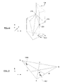
- FIG. 2 provides a pictorial representation of a three-dimensional gamut of determined chromaticity and intensity values of which a given solid state lighting system is capable of generating.
- FIG. 3 provides another pictorial representation of a three-dimensional gamut of determined chromaticity and intensity values of which a given solid state lighting system is capable of generating where the gamut represents a larger number of intensities capable of being generated by the solid state lighting system when compared to that of FIG. 2 .
- FIG. 4 provides a pictorial representation comparing the gamuts of FIGS. 2 and 3 .
- FIG. 5 illustrates an example of electrical components of a solid state lighting system and components for setting the solid state lighting system.
- FIG. 6 illustrates a block diagram of the control circuitry for a solid state lighting system in accordance with the disclosed concepts.
- FIG. 7 illustrates a first exemplary configuration of control circuitry for controlling a plurality of light fixtures.
- FIG. 8 illustrates an array of outputs of a number of light fixtures.
- FIG. 9 illustrates a second exemplary configuration of control circuitry for controlling a plurality of light fixtures.
- FIG. 10 illustrates the processing flow for validating a given chromaticity corresponding to an input setting to the solid state lighting system described herein to determine if the lighting system is capable of generating light having the given chromaticity.
- FIGS. 11A and B illustrate the processing flow for validating a given intensity corresponding to an input setting to the solid state lighting system described herein to determine if the solid state lighting system is capable of generating light having the given intensity.
- FIG. 12 provides a partial pictorial representation of the gamut of FIG. 3 for illustrating which planes of the gamut are evaluated for a given input of chromaticity and intensity.
- FIG. 13 provides a partial pictorial representation of the gamut of FIG. 3 in the x-y plane for illustrating which planes of the gamut are evaluated for a given input of chromaticity and intensity.
- FIG. 14 illustrates a gamut in the x-y plane.
- FIG. 15 illustrates a gamut in the x-y plane.
- FIG. 16 illustrates a known CIE Chromaticity diagram.
- solid state lighting systems may be set to generate combined light having desired colors and intensities of which the lighting system is capable of generating.
- FIG. 1 is a partial block diagram and a cross-sectional illustration of the light fixture.
- the fixture For illumination or task lighting applications, the fixture emits light in the visible spectrum.
- color and/or intensity of light may appear different from fixture to fixture for the same input setting. This typically occurs when multiple fixtures are controlled to generate a color and/or intensity of which at least one of the fixtures is incapable of generating.
- the inventors have found a way to manage the foregoing problem by validating the input setting to each fixture by determining whether the respective fixture is capable of generating light according to the input setting. If validated, the light fixture may generate the corresponding light. If invalid, the light fixture may be controlled to not output any light or controlled to output light where color and/or intensity settings have been adjusted specific to the capabilities of the light fixture.
- the make up of such an exemplary fixture it is helpful to first understand the make up of such an exemplary fixture.
- FIG. 1 depicts a lighting system 100 , by way of example, of a type that may be configured to respond to input settings as taught herein to generate light output.
- the illustrated system 100 includes an optical cavity 102 having a diffusely reflective interior surface, to receive and combine light energy of different colors/wavelengths.
- the disclosed apparatus may use a variety of different structures or arrangements for the optical integrating cavity.
- the illustrated cross-section of the optical cavity 102 is approximately hemispherical.
- the optical cavity 102 may have various shapes such as semi-cylindrical with the cross-section taken perpendicular to the longitudinal axis. Other applications may call for rectangular or square cross-sections.
- At least a substantial portion of the interior surface(s) of the optical cavity 102 exhibit(s) diffuse reflectivity. It is desirable that the cavity surface have a highly efficient reflective characteristic, e.g. a reflectivity equal to or greater than 90%, with respect to the relevant light wavelengths.
- the interior surface of that illustrated by FIG. 1 is highly diffusely reflective to energy in the visible, near-infrared, and ultraviolet wavelengths.
- a hemispherical dome 104 and a substantially flat cover plate 106 form the optical cavity 102 .
- the interior facing surfaces of the dome 104 and the cover plate 106 are highly diffusely reflective, so that the resulting cavity 102 is highly diffusely reflective with respect to the radiant energy spectrum produced by the system 100 .
- a portion or all of the inner surface of the dome 104 have a highly efficient reflective characteristic, e.g. a reflectivity equal to or greater than 90%, with respect to the relevant wavelengths, and the facing surface of the cover plate 106 is at least substantially specular in nature.
- the volume or chamber 102 is an integrating type optical cavity.
- the dome 104 and plate 106 may be formed as an integral unit.
- the optical integrating cavity 102 has an optical aperture 108 as a transmissive path for allowing emission of combined radiant energy.
- the aperture 108 is a passage through the approximate center of the cover plate 106 , although the aperture may be at any other convenient location on the plate or the dome. Because of the diffuse reflections within the cavity 102 , light within the cavity is integrated, mixed or combined before passage thereof out of the aperture 108 . In other words, the system 100 is capable of emitting combined light downward through the aperture 108 .
- the light fixture part of the system 100 may be oriented in any desired direction to perform a desired application function, for example to provide visible illumination of persons or objects in a particular direction or location with respect to the fixture or to illuminate an area or room. Although only a single aperture is shown, the fixture 112 may include multiple apertures. Also, in some applications, it may be desirable for some of the light combined within the cavity 102 to pass through a transmissive portion of the cavity wall.
- the system 100 also includes light emitting diodes (LEDs) 110 as the sources of light energy although other types of light sources, such as other solid state light emitters, may be used.
- the sources are different primary color (RGB) LEDs 110 , two of which (Red and Green) are visible in the illustrated cross-section.
- RGB primary color
- the Blue LED (not shown) would be seen in a different cross section. Although only one LED of each color is shown, typical implementations use a plurality of LEDs of one or more or all of the colors.
- the LEDs 110 supply light energy into the interior of the optical integrating cavity 102 . As shown, the points of emission into the interior of the optical integrating cavity are not directly visible through the aperture 108 . Direct emissions from the sources reflect off a surface of the cavity 102 .
- the cavity 102 effectively integrates, mixes or combines the light energy of different colors, so that the integrated or combined light emitted through the aperture 108 includes the light energy of all the various wavelengths in relative amounts substantially corresponding to the relative amounts that the sources input into the cavity 102 .
- the diffuse reflective processing by the cavity converts the multiple point sources to a virtual source of light, of the combined light color and intensity at the aperture 108 .
- the virtual source will have a high degree of uniformity across the area of the aperture and typically will not exhibit pixilation.
- the integrating or mixing capability of the cavity 102 serves to project light of any color, including white light, by adjusting the amount of light output by the various sources 110 coupled into the cavity 102 .
- U.S. Pat. No. 6,995,355 to Rains, Jr. et al. the disclosure of which is entirely incorporated herein by reference, provides additional information as to the materials; structure and configuration of numerous examples of systems and various elements thereof of the type exemplified by FIG. 1 .
- control of the drive currents applied to drive light production by the LEDs 110 controls the color characteristics of the combined light output by the fixture 112 .
- the circuitry may also modulate the drive signals to control amounts of energy output by each solid state lighting element. Examples of the control circuit 114 will be discussed in detail below.
- multiple fixtures tend to generate light of different color and/or intensity where the input parameters are near or beyond the output limitations of the multiple fixtures. This occurs when spectral output characteristics from one LED 110 to the next differ. Taking a red LED 110 as an example, one red LED may be capable of generating vibrant red colors of light at a maximum intensity whereas another LED may be capable of generating less vibrant red colors of light at a maximum intensity.
- Two light fixtures, as shown in exemplary FIG. 1 with such LEDs will have different output characteristics due to the difference in spectral output of the red LEDs when the LEDs of the two fixtures are driven with the same current levels. This problem compounds as more and more of the same fixtures are manufactured and are used in the same setting where differences between like light fixtures are more prevalent.
- two different fixtures may generate noticeably different output light for the same input setting.
- Various techniques are known for setting systems to provide substantially similar light outputs for a given input setting. The inventors have found that a light fixture can validate light input settings to generate light of which the fixture are capable of generating.
- the foregoing may be accomplished by setting each fixture to generate light for color parameter input settings and/or configuring the system to determine if input settings correspond to light outputs that fall within a gamut which represents the range of color and/or intensities of light of which the fixture is capable of generating.
- the gamut may be based on the CIE 1931 Chromaticity Diagram space, such as that illustrated by FIG. 15 , specific for the operating conditions of each light fixture.
- This Chromaticity Diagram space uses a Cartesian coordinate system with points defined as (x, y, z), which can be converted to (x, y, Y) coordinates as described above.
- the x and y-coordinates define a chromaticity, and Y-coordinates define intensity. All colors and corresponding intensities within the gamut are achievable for a given fixture, while all colors and corresponding intensities outside of the gamut cannot be achieved for the given fixture.
- the gamut can be defined by a few key points in a 3-d coordinate system having x, y, Y axes. For instance, it is impossible to achieve chromaticity points outside of the gamut, because chromaticities are achieved by mixing certain proportions of the color of respective LEDs in a given fixture. Therefore, a footprint of the gamut, i.e., the gamut in the x-y plane of the 3-d coordinate system, may be a triangle formed by connecting points representing each of the colors of the LEDs in a given fixture. As described herein, the primary colors of red, green and blue correspond to the colors of the LEDs.
- Light intensity is additive regardless of chromaticity.
- the limitations on the maximum intensity that a fixture can generate can be determined. Therefore, a lighting system will generate a maximum attainable intensity which is possible for the system when all LEDs of the system are set to respective maximum intensities.
- FIG. 2 illustrates the gamut 200 defined according to the 3-d coordinate system as described above.
- Point 202 represents the (x,y) coordinate for the color of green on the 3-d coordinate system when the green LED is turned on and the blue and red LEDs are turned off.
- Point 204 represents the intensity measurement for the color at point 202 .
- the height of point 204 corresponds to the (Y) value of the (x,y,Y) coordinate that represents a maximum attainable intensity of light when the green LED is on at a maximum output.
- the (Y) value may be determined using the calibrated sensor discussed below with respect to FIG. 5 .
- points 208 and 210 represent the (x,y) coordinate for the color of red and the associated maximum attainable intensity (the (Y) value) of light when the red LED is on at a maximum output and the green and blue LEDs are turned off.
- Point 206 represents the (x,y) coordinate for the color of blue, and the highest of point 207 corresponds to the associated maximum attainable intensity of light when the blue LED is on at a maximum output and the red and green LEDs are turned off.
- the gamut 200 may be defined according to at least four (x,y,Y) points.
- the intensity values (Y) for the respective colors typically will differ, e.g. depending on the number of respective color LEDs and/or differences in LED performance.
- the fourth point 212 corresponds to a summation of all measured intensities (1)-(3), which corresponds to white light. However, this point may be measured by turning on red, green and blue LEDs at respective maximum outputs.
- the points 204 , 207 , 210 , and 212 form a roughly pyramidal top or upper boundary of the gamut.
- Points 202 , 204 , 206 , 207 , 208 and 210 form planes which form facets of the gamut 200 .
- a first plane 214 having points 202 , 204 , 207 and 206 bound one side of the gamut 200 ;
- a second plane 216 having points 206 , 207 , 208 and 210 bound another side;
- a third plane 218 having points 202 , 204 , 208 and 210 bound yet another side of the gamut 200 .
- each plane 214 , 216 , 218 intersect delineates the outer boundary of the gamut 200 .
- the lower bound of intensity is when all LEDs are off.
- the intensity measurements when each respective LED is turned on and the other respective LEDs are turned off may be summed to determine the maximum attainable intensity of light that a lighting system is capable of generating.
- the maximum attainable intensity of light that a lighting system is capable of generating may be determined by turning all LEDs on to respective maximum outputs and measuring the intensity of light using a calibrated sensor, as discussed below with respect to FIG. 5 .
- red, green and blue LEDs corresponding to the primary colors when all LEDs are turned on the lighting system generates white light.
- the lighting system generates white light of a particular color (e.g. temperature) at an intensity equal to the maximum attainable intensity of the lighting system.
- the white light at the maximum attainable intensity of the system corresponds to point 212 . Because the outputs of all LEDs are maximized, point 212 corresponds to the apex of the gamut 200 .
- Points 212 , 204 and 207 form a fifth plane 222 ; points 212 , 210 and 207 form a sixth plane 224 ; and points 212 , 210 , and 204 form a seventh plane 226 , all of which intersect at point 212 forming the apex of the gamut 200 . Moreover, these planes form a top contour of the gamut 200 . Furthermore, the first plane 212 and fifth plane intersect at a line formed by points 204 and 207 . Other planes intersect forming lines, as illustrated. Accordingly, the shape of the gamut 200 may be defined by a plurality of intersecting planes. The lines formed by intersecting planes form facets of the gamut having polygonal shapes.
- the gamut 300 of FIG. 3 comprises ten intersecting planes to form ten polygonal facets of the gamut 300 .
- the additional colors of light and associated intensities are generated by turning two of the three LEDs on and the other off in all combinations.
- point 302 represents the color of cyan when both green and blue LEDs are turned on.
- Point 304 corresponds to the maximum achievable intensity when both green and blue LEDs are turned on to maximum outputs.
- Point 306 represents the color of magenta when both red and blue LEDs are turned on.
- Point 308 corresponds to the maximum achievable intensity when both red and blue LEDs are turned on to maximum outputs.
- Point 310 represents the color of yellow when both red and green LEDs are turned on.
- Point 311 corresponds to the maximum achievable intensity when both red and blue LEDs are turned on to maximum outputs.
- the gamut 300 is formed by at least ten intersecting planes—the first plane 312 contains at least points 202 , 204 , 304 , 207 , and 206 ; the second plane 314 contains points 207 , 304 and 212 ; and so on for each facet of the gamut 300 as illustrated.
- the intersecting planes form a plurality of facets of the gamut 300 where each facet has a polygonal shape, as illustrated by FIG. 3 .
- the shape of the gamut 300 for the maximum achievable intensities can be described with several planes which are defined by all combinations of the red, green, blue, yellow, cyan, magenta, and white points. All planes will converge on the white point or apex 212 .
- FIG. 4 illustrates gamut 200 superimposed on gamut 300 .
- factoring other colors as discussed above provides a gamut 300 which covers a broader range of intensities 402 of which the lighting system is capable of generating.
- an lighting system which is set according to gamut 300 would require greater computation to determine whether or not an input color parameter is within the gamut.
- the lighting system such as that illustrated by FIG. 1 may be set to output light that has a coordinate in the 3-d system that is within the gamut 200 or 300 or similar shaped gamut.
- exemplary sources of radiant electromagnetic energy include various conventional forms of incandescent, arc, neon and fluorescent lamp.
- at least some of the sources take the form of solid state light emitting elements.
- solid state light emitting elements essentially includes any of a wide range light emitting or generating device formed from organic or inorganic semiconductor materials. Examples of solid state light emitting elements include semiconductor laser devices.
- LEDs solid state lighting elements
- This class of devices encompasses any and all types of semiconductor diode devices that are capable of receiving an electrical signal and producing a responsive output of electromagnetic energy.
- LED should be understood to include light emitting diodes of all types, light emitting polymers, organic diodes, and the like. LEDs may be individually packaged, as in the illustrated examples. Of course, LED based devices may be used that include a plurality of LEDs within one package, for example, multi-die LEDs that contain separately controllable R, G and B LEDs within one package. Those skilled in the art will recognize that “LED” terminology does not restrict the source to any particular type of package for the LED type source.
- Solid state lighting elements may include one or more phosphors and/or nanophosphors based upon quantum dots, which are integrated into elements of the package or light processing elements to convert at least some radiant energy to a different more desirable wavelength.
- the color of light or other electromagnetic radiant energy relates to the frequency and wavelength of the radiant energy and/or to combinations of frequencies/wavelengths contained within the energy. Many of the examples relate to colors of light within the visible portion of the spectrum, although the teachings may also apply to systems that utilize or emit other energy.
- solid state light emitting elements may be configured to generate electromagnetic radiant energy having various bandwidths for a given spectrum (e.g. narrow bandwidth of a particular color, or broad bandwidth centered about a particular), and may use different configurations to achieve a given spectral characteristic.
- a white LED may utilize a number of dies that generate different primary colors which combine to form essentially white light.
- a white LED may utilize a semiconductor that generates light of a relatively narrow first spectrum that acts as a pump. The light from the diode “pumps” a phosphor material or quantum dots contained in the LED package, which in turn radiates a different typically broader spectrum of light that appears relatively white to the human observer.
- FIG. 5 illustrates a high-level block diagram of a lighting system 500 and sensors used to control and set the lighting system 500 .
- the lighting system 500 includes a microcontroller unit 502 which controls the digital-to-analog converters and LED drivers 504 for controlling the LED light sources 506 .
- the system 500 which outputs combined light (examples of the manner in which the set of LED light sources 100 output combined light is discussed above with FIG. 1 ).
- the set of LEDs 506 will include one or more LEDs of each of two, three or more light colors. At least for each different color of the LEDs, there will be an associated digital-to-analog converter and LED driver to control the output amount of that color of light. While FIG. 1 illustrates LED light sources 506 , typically red (R), green (G) and blue (B) LEDs, it should be appreciated that other solid state light emitting elements could be used as described above.
- the lighting system 500 also includes a sensor 408 discussed below.
- the lighting system 500 of FIG. 5 it is useful to set the lighting system 500 of FIG. 5 according to its operational limitations because when the input 510 is applied to the LED light sources 506 in RGB coordinates 512 , the spectral output of each LED light source 506 tends to be slightly different from fixture to fixture as compared to the desired output represented by the input 510 . Specifically, the color of light output by combination of light from the LED light sources 506 may be different from the desired color represented by the input 510 for the reasons described above. Also, it should be appreciated that while FIG. 5 illustrates an input 510 in chromaticity coordinates xyY, the input may be tristimulus values XYZ or even RGB values.
- An input 510 of RGB values may be applied to the MCU 502 or directly to the digital and analog converter and LED drivers 504 .
- this description refers to the color and/or intensity input setting values 510 in chromaticity coordinates xyY applied to the MCU 502 .
- the color input setting 510 may come from a user interface device or a central control system; although during calibration or setting up the system, the input settings 510 may be automatically input, e.g. by computer 514 .
- setting up the lighting system may be achieved by interfacing a calibrated sensor 516 and computer 514 with the lighting system 500 .
- the sensor 516 is configured to sense and measure intensity of the spectral output of the LED light sources 506 , and output measurements 518 containing at least intensity (Y) measurements.
- the sensor may be configured to measure chromaticity (x,y) as well.
- measurements may be taken in or converted to tristimulus coordinates, such as XYZ or other coordinates that take into account various color sensitivity functions which correlate generally with the response to the human eye and converted to an intensity value.
- the computer 514 receives measurements from the sensor 516 .
- the computer 514 determines a gamut of chromaticity and intensity values in which the system 500 is capable of generating.
- the gamut may be represented by a formation of intersecting planes, as illustrated by FIGS. 2 and 3 . Points in the 3-d coordinate system representing the formation may be loaded into the MCU 502 or stored in external memory (not shown) for use when the system 500 is in actual operation to determine whether or not an input 510 can be displayed by the given optical system. The particulars of the measurements taken will be discussed further below.
- FIG. 6 illustrates a block diagram of the control circuitry for a lighting system in accordance with the disclosed concepts.
- the set of sources of light of the various types takes the form of a LED array 602 containing the plurality of LEDs 1110 forming the fixture 112 such as that illustrated by FIG. 1 .
- the control circuitry of FIG. 6 may control a plurality of fixtures 112 in various configurations such as that illustrated by FIG. 8 . However, it should be appreciated that many other configurations of the plurality of fixtures 112 are indeed possible.
- the control circuitry 612 separately controls the plurality of Red LEDs, the plurality of Green LEDs, the plurality of Blue LEDs, etc.
- the system may include a plurality of control circuits 612 each for controlling a respective fixture 112 among a plurality of light fixtures 112 .
- master control circuitry 902 may be used to control the plurality of the control circuits 612 .
- the control circuitry discussed herein is applicable in many different arrangements where the control circuitry controls multiple sets of LEDs or dedicated control circuitry controls each one of a plurality of sets of LEDs.
- the LED array 602 comprises two or more LEDs of each of the three primary colors red (R), green (G) and blue (B), each of which is represented by LED blocks 604 , 606 and 608 . As discussed above, these LED blocks may connect to one fixture 112 or span a plurality of such fixtures 112 . Either configuration is possible. Moreover, the array 602 is not limited to RGB LEDs. White LEDs also may be included, or white LEDs of two or more different color characteristics may be substituted for the RGB LEDS.
- the LED array 602 may also include a number of additional or ‘other’ LEDs 610 .
- the LED array 602 may include white, IR or UV LEDs for various purposes or additional LEDs as “sleepers” that initially would be inactive.
- the Red LEDs 604 , Green LEDs 606 and Blue LEDs 608 might normally be active.
- the LEDs 610 would be sleeper LEDs, typically including one or more LEDs of each color used in the particular system. Sleeper LEDs may be activated when needed, typically in response to feedback indicating a need for increased output (e.g. due to decreased performance of the originally active LEDs).
- the electrical components shown in FIG. 6 also include a LED control system 612 .
- the control system 612 includes LED driver circuits 624 , 626 , 628 , 630 for the various LEDs as well as a microcontroller 614 .
- the microcontroller 614 controls the LED driver circuits 624 , 626 , 628 , 630 via digital-to-analog (D/A) converters 616 , 618 , 620 , 622 . More particularly, the driver circuit 624 drives the Red LEDs 604 ; the driver circuit 626 drives the green LEDs 606 ; and the driver circuit 628 drives the Blue LEDs 608 . In a similar fashion, when active, the driver circuit 630 provides electrical current to the other LEDs 610 .
- D/A digital-to-analog
- the other LEDs provide another color of light, and are connected in series, there may be a single driver circuit 630 . If the LEDs are sleepers, it may be desirable to provide a separate driver circuit 630 for each of the LEDs 610 .
- the intensity of the emitted light of a given LED 604 , 606 , 608 , 610 is proportional to the level of current supplied by the respective driver circuit 624 , 626 , 628 , 630 .
- the current output of each driver circuit is controlled by the higher level logic of the system.
- the driver circuits 624 , 626 , 628 , 630 supply electrical current at the respective levels for the individual sets of LEDs 604 , 606 , 608 , 610 to cause the LEDs 604 , 606 , 608 , 610 to emit light.
- the microcontroller 614 controls the LED driver circuit 624 via a D/A converter 616
- the microcontroller 614 controls the LED driver circuit 626 via a D/A converter 618 .
- the microcontroller 614 controls the LED driver circuit 628 via a D/A converter 620 .
- the amount of the emitted light of a given LED set 604 , 606 , 608 is related to the level of current supplied by the respective driver circuit 624 , 626 , 628 .
- the microcontroller 614 controls the LED driver circuit 630 via the D/A converter 622 .
- the driver circuit 630 provides electrical current to the other LEDs 610 . If the LEDs are sleepers, it may be desirable to provide a separate driver circuit and D/A converter pair, for each of the LEDs 610 or for other sets of LEDs of the individual primary colors.
- the LED driver circuits 624 , 626 , 628 , 630 , the D/A converters 616 , 618 , 620 , 622 and the microcontroller 614 receive power from a power supply 632 , which is connected to an appropriate power source (not separately shown).
- the power source will be an AC line current source, however, some applications may utilize DC power from a battery or the like.
- the power supply 632 provides AC to DC conversion if necessary, and converts the voltage and current from the source to the levels needed by the LED driver circuits 624 , 626 , 628 , 630 the D/A converters 616 , 618 , 620 , 622 and the microcontroller 614 .
- the D/A converters 616 receives a command for a particular level from the microcontroller 614 .
- the converter 616 generates a corresponding analog control signal, which causes the associated LED driver circuit 624 to generate a corresponding power level to drive the Red LED 604 .
- the Red LED 604 in turn outputs light of a corresponding intensity.
- the D/A converter 624 will continue to output the particular analog level, to set the red LED 604 intensity in accord with the last command from the microcontroller 614 , until the microcontroller 614 issues a new command to the D/A converter 616 .
- the other D/A converters 618 , 620 , 622 , the LED driver circuits 626 , 628 , 630 and LEDs 606 , 608 , 610 operate in a similar fashion.
- the example uses current control, to control the amount of light output of each block of LEDs, and thus the light contribution thereof to the combined light output of the system.
- control techniques may be used, such as various forms of controlled pulse modulation.
- the microcontroller 614 typically includes or has coupled thereto random-access memory (RAM) for storing data and read-only memory (ROM) and/or electrically erasable read only memory (EEROM) for storing control programming and any pre-defined operational parameters.
- RAM random-access memory
- ROM read-only memory
- EEROM electrically erasable read only memory
- the microcontroller 614 itself comprises registers and other components (not shown) for implementing a central processing unit (CPU) and possibly an associated arithmetic logic unit (not shown).
- the CPU implements the program to process data in the desired manner and thereby generate desired control outputs.
- the microcontroller 614 is programmed to control the LED driver circuits 624 , 626 , 628 , 630 to set the individual output intensities of the LEDs to desired levels, so that the combined light emitted from the aperture 108 of the cavity 102 has a desired spectral characteristic and a desired overall intensity.
- the microcontroller 614 may be programmed so that when it receives control inputs via a user interface 640 specifying the particular color, it translates color input values into appropriate control values, as discussed further below.
- the user interface 640 is shown as an element of the system closely associated with the microcontroller 614 and other electrical elements of the lighting system.
- system may include a communication interface or other link to a remote device or to some other system that provides the user interface (see e.g. above-incorporated U.S. Pat. No. 6,995,355 to Rains, Jr. et al., for additional information).
- the microcontroller 614 receives information concerning the light output from a feedback sensor 634 .
- the feedback sensor 634 may include a color sensor 636 which measures the frequency distribution (e.g. intensity of multiple frequency components) of the combined light.
- Other types of feedback sensors such as a thermal temperature sensor 638 may be used, for example, in or near the optical integrating cavity 102 . While the feedback sensor 634 as illustrated includes both a thermal temperature sensor 638 and the color sensor 636 , the feedback sensor 634 may contain only one or the other.
- the system may include a separate intensity sensor, or the microcontroller may control the sensor 636 to also provide an overall indication of intensity.
- the thermal temperature sensor 638 may be a simple thermoelectric transducer with an associated analog to digital converter, or a variety of other temperature detectors may be used.
- the color sensor 636 detects color distribution in the integrated light within the optical integrating cavity 102 .
- the sensor 636 may be mounted on the same board as one or more of the LEDs, or as in the example of FIG. 1 , the sensor 636 may be coupled to a wall of the cavity. Some small amount of the integrated light passes through a point on a wall of the cavity 102 , therefore it is sufficient to sense color at that point on the cavity wall.
- a variety of color sensing devices may be used to implement the sensor 636 .
- the microcontroller 614 monitors color using an RGB light sensor 636 that is a digital compatible sensor which provides a single output in the form of a pulse train of a frequency that is proportional to the intensity of the input light.
- the color sensor 636 may incorporate selectable color filtering. In such a case, the sensor applies one of the color filters for color of light to be sensed in response to several bits of a control signal from the microcontroller 614 . The frequency of the output then is proportional to the sensed light intensity of the selected color of light (R, G or B).
- the microcontroller 614 may select a color and instruct the color sensor 636 to sense the intensity of that color through the appropriate filter, and as a result, the microcontroller 614 receives a pulse train of frequency proportional to the measured intensity of light of the selected color. The microcontroller 614 then selects another color and receives a pulse train of frequency proportional to the measured intensity of light of that second color. The microcontroller 614 then selects a third color and receives a pulse train of frequency proportional to the measured intensity of light of that third color. In this way, the sensor 636 can provide information to the microcontroller 614 as to the measured intensity of each primary color of light (R, G or B) within the combined light being generated by the system. The microcontroller 614 may also control the sensor 636 to obtain a similar reading of total intensity (unfiltered) of the combined light. The process may periodically repeat as the system takes additional measurements of the color distribution.
- the control circuit 612 and specifically the microcontroller 614 is capable of setting the drive current and thus the output intensity for each color, in order to achieve a desired uniform color distribution in the combined light generated further to a process described in detail below.
- the microcontroller 614 translates frequency of the signals from the color sensor 636 into data that it uses as a representation of intensity for each sensed color of light.
- the microcontroller 614 uses the color intensity data as feedback data, to control the DACs to set the drive current value for each color, to insure that the combined light generated by the system exhibits and maintains the desired color distribution.
- the microcontroller 614 also is responsive to the detected color distribution to selectively activate the inactive light emitting diodes 614 as needed, to maintain the desired color distribution in the combined light.
- FIG. 6 provides a detailed diagram of a lighting system
- the remainder of the description will refer to the high-level block diagram illustrated by FIG. 5 .
- an (x,y,Y) point 510 may be input to an MCU 502 .
- the MCU 502 interprets and executes the input point 510 to generate a desired color and intensity corresponding to the (x,y,Y) point 510 .
- the first step is to insure that the input 510 is achievable on the fixture. In other words, it needs to be determined whether or not the (x,y,Y) input 510 is within a gamut, discussed above.
- each of the important coordinates of the points described in the previous section is measured while determining operational characteristics of the lighting system
- Validating input 510 can be broken into two general steps. First, the chromaticity of the corresponding (x,y) coordinate is validated. Then, the intensity of the (Y) coordinate is validated. If both steps are valid, then the point has been validated as an achievable point. If achievable, the MCU sets the LED outputs to corresponding levels. If not achievable, there are a variety possible ways the MCU might proceed, examples of which are discussed later.
- the (x,y) coordinates of the input 510 are within the gamut, such as the exemplary gamuts 200 , 300 described above. This can be accomplished by comparing the input 510 coordinates to the lines which are defined the intersection of each of the plurality of planes forming the gamut or the edge of each facet. Specifically, the points that define these lines have been pre-programmed in the fixture and are accessible for validating any given input 510 .
- FIG. 10 illustrates an exemplary flow chart for validating such an input 510 .
- the lines to which to compare the input 510 corresponds to those that form the footprint of the gamut in FIGS. 2 and 3 . These lines are as follows: (1) line formed by points 202 and 206 (“GB line”), (2) line formed by points 206 and 208 (“BR line”), and (3) line formed by points 208 and 202 (“RG line”).
- FIG. 10 illustrates a flowchart of the algorithm to evaluate chromaticity on the input 510 .
- the order in which the lines are evaluated is not important.
- “x_user” corresponds to the x-coordinate of the input 510
- “y_user” corresponds to the y-coordinate of the input 510
- “m” corresponds to the slope of the line in the 3-d coordinate system to which the input 510 is compared
- “y_test” corresponds to the y value result solved for Equation 1 discussed below.
- the algorithm represented by the flowchart of FIG. 10 assumes that the red and blue points have a smaller y-coordinate than the green point, and the blue point has a smaller x-coordinate than the red point.
- the algorithm assumes that the red point resides in the reddish region of the CIE 1931 Chromaticity Diagram or 3-d coordinate system, the green point resides in the greenish region of the diagram and the blue point resides in the bluish region of the diagram, as discussed above.
- Equation 1 The general equation for the lines in the x-y plane forming the gamuts 200 , 300 of FIGS. 2 and 3 , respectively is shown in Equation 1 below. Coordinates (x 1 ,y 1 ) and (x 2 ,y 2 ) are the end points of the lines forming the gamut in the x-y plane, i.e., the GB line, BR line or RG line, and (y 2 ⁇ y 1 )/(x 2 ⁇ x 1 ) corresponds to the slope “m.”
- the GB line with the foregoing coordinates would have a slope “m” of 5 on the x-y plane.
- the BR line with the foregoing coordinates would have a slope “m” of 1 ⁇ 4 on the x-y plane.
- the RG line with the foregoing coordinates would have a slope “m” of ⁇ 4/3 on the x-y plane.
- Equation 1 is evaluated for the RG line.
- y_test or the output of Equation 1 would equal 6.
- x_user is evaluated when slopes of lines are undefined. In the case of the RG line, the slope of ⁇ 4/3 is not an undefined quantity. Accordingly, the result of step 1004 would be false or no.
- y_user is evaluated when the slope is positive. In the case of the RG line, the slope of ⁇ 4/3 is a negative value. Accordingly, the result of step 1006 would be false or no.
- y_user is evaluated when the slope is negative.
- the slope of ⁇ 4/3 is indeed a negative value.
- the result of step 1008 is true. Accordingly, the user point of (2,4) is within the gamut when compared with the RG line only.
- steps similar to steps 1002 - 1008 need to be repeated for the GB and BR lines.
- Equation 1 is evaluated for the GB line.
- y_test (or the output of Equation 1) would equal 6.
- step 1012 because the slope of 5 for line GB is not an undefined value, the result would be false.
- step 1014 because the slope has positive value, y_user and y_test are evaluated. Specifically, in step 1014 , it is determined whether or not y_user is less than or equal to y_test. Because 4 (y_user) is less than 6 (y_test), the result of step 1014 is true or yes, and the next step is to evaluate line BR. Had the result of step 1014 been false, step 1016 would have been conducted where if the slope of the GB line is negative, it is determined whether or not y_user is greater than or equal to y_test.
- Equation 1 is evaluated for the BR line.
- y_test (or the output of Equation 1) would equal 5/4.
- step 1020 because the slope of 5/4 for line BR is not an undefined value, the result would be false.
- step 1022 it is determined whether or not y_user is greater than or equal to y_test. It is not necessary to determine whether or not the slope is positive or negative because the position of the input 510 has already been evaluated for the other lines. Because 4 (y_user) is greater than 5/4 (y_user), the result of step 1022 is true. Accordingly, the input 510 is inside the gamut for coordinates (x,y), and the user set point is considered valid at step 1024 for the (x,y) coordinates.
- step 1026 may be reached when it is determined that the point 510 corresponds to a position on a side of the RG line, the GB or the BR line that places the point outside of the gamut in the x-y plane.
- the intensity of the input 510 needs to be validated.
- the maximum intensity for any given chromaticity in the gamut 200 , 300 is governed by a series of planes. Each plane is defined by three points, where the white point is common among all planes corresponding to point 212 which is the apex of the gamut 200 , 300 .
- RWY max plane plane with points 210 , 212 , 311
- GWY max plane plane with points 204 , 212 , 311
- GWC max plane plane with points 204 , 212 , 304
- BWC max plane plane with points 207 , 212 , 304
- BWM max plane plane with points 210 , 212 and 308
- R stands for red, G for green, B for blue, W for white, Y for yellow, C for cyan and M for magenta on the 3-d coordinate space of FIG. 3 .
- the RWY max plane corresponds to the facet at the top of the gamut 300 that spans the red, white and yellow colors, and so on for each respective plane.
- FIG. 11A and B it is determined which of the foregoing planes apply to the chromaticity of the input 510 .
- FIG. 12 is a partial illustration of the gamut 300 for describing conceptually the determination of which plane applies according to the flowchart of FIGS. 11A and B.
- Each plane that forms the top of the gamut 300 can be contained within separate columns extending along the Y axis. Taking the RWM max plane for example, a column may be formed along the Y axis where each point 210 , 212 , 308 is in line with a respective vertices 1204 of the column.
- the RWM max plane applies to the (x,y) input according to the flowchart of FIGS.
- the (x,y) point is inside the column 1202 .
- a determination of which plane applies can be accomplished by comparing the input 510 to the lines which describe the intersections of planes RWY max , GWY max , etc. described above as projected on to the x-y plane in the 3-d coordinate.
- the line from point 210 to point 212 (“RW max line”) in the gamut 300 can be represented as the RW line which is projected on the x-y plane by ignoring the Y coordinate and using Equation 1 discussed above.
- FIG. 13 illustrates a projection of each of the RWY max plane, GWY max plane, GWC max plane, BWC max plane, BWM max plane, and RWM max plane as projected on the x-y plane of the gamut 300 .
- FIG. 13 For explanation purposes, as illustrated by FIG. 13 consider a first (x_user, y_user) point 1302 and a second (x_user, y_user) point 1304 that are input to the system (input 510 ) as illustrated by FIG. 5 . Because the RW line and CW line are part of the same line, the results of steps 1104 and 1106 may rule out planes that do not apply.
- the first point 1302 would have a y_user coordinate that places the point 1304 above the RW and CW lines. Thus, the RWM max plane, BWM max plane and BWC max plane do not apply. Steps 1108 - 1124 of FIG. 11A would be performed to determine which plane applies.
- the second point 1304 would have a y_user coordinate that places the point 1302 below the RW and CW lines as illustrated.
- the RWY max plane, GWY max plane and GWC max plane do not apply. Steps 1126 - 1142 of FIG. 11B would be performed to determine which plane applies.
- Equation 1 is evaluated for the RW line at x_user to yield the result as y_user.
- the slope of line RW is positive and is an extension of line CW.
- the y_user would be greater than or equal to the y_test value—the result of step 1302 would be true or yes.
- the y_user value would be less than or equal to the y_test value—the result of step 1304 would be true or yes.
- step 1108 - 1112 are the same as steps 1102 - 1108 except for evaluation of the BW line. If the results of both steps 1110 and 1112 are false or no, the determination is made that the (x_user, y_user) is applicable to the RWY max plane. However, this would not be the case for point 1302 in this example. In other words, if either of steps 1110 or 1112 are true, step 1116 would be performed.
- steps of 1106 - 1120 are the same as steps 1102 - 1108 except for evaluation of the GW line. If the results of both steps 1118 and 1120 are false or no, the determination is made that the (x_user, y_user) is applicable to the GWY max plane. However, this would not be the case for point 1302 in this example. In other words, if either of steps 1110 or 1112 are true, it would be determined that GWC max plane is applicable.
- Equation 1 is evaluated for the RW line at x_user to yield the result as y_user.
- the slope of line RW is positive and is an extension of line CW.
- the y_user would be less than the y_test value—the result of step 1302 would be false or no.
- the result of step 1106 would be false.
- the RWY max plane, GWY max plane and GWC max plane would be ruled out.
- steps 1126 - 1130 are the same as steps 1102 - 1108 except for evaluation of the BW line. If the results of both steps 1128 and 1130 are false or no, the determination is made that the (x_user, y_user) is applicable to the BWC max plane. However, this would not be the case for point 1304 in this example. In other words, if either of steps 1128 or 1130 are true, step 1134 would be performed.
- steps of 1134 - 1138 are the same as steps 1102 - 1108 except for evaluation of the GW line. If the results of both steps 1136 and 1138 are false or no, the determination is made that the (x_user, y_user) is applicable to the RWM max plane. However, this would not be the case for point 1304 in this example. In other words, if either of steps 1136 or 1138 are true, it would be determined that BWM max plane is applicable.
- the next step is to compare the intensity of the input 510 to the maximum achievable intensity for the lighting system described by the appropriate plane.
- the maximum achievable intensity corresponds to the apex at point 212 of the gamut 200 , 300 for white line.
- each (x,y) point in the gamut 200 , 300 has a specific maximum intensity because the planes that form the top of the gamut 200 , 300 traverse the x,y,Y space, i.e., the Y value of each plane is not constant.
- the applicable plane determined according to the flowchart of FIGS. 11A and B may be any of the RWY max plane, GWY max plane, GWC max plane, BWC max plane, BWM max plane and RWM max plane.
- Each of the foregoing planes may be defined according to three points.
- the BWM max plane may be defined by points 207 , 308 and 212 as illustrated by FIG. 3 . These three points which define the applicable plane may be used to evaluate if the maximum achievable intensity for the chromaticity (x user ,y user ) input 510 by the user according to Equation 2 shown below.
- Equation 2 Y max represents the maximum achievable intensity at the chromaticity (x user ,y user ) input 510 .
- the points (x 1 ,y 1 ,Y 1 ), (x 2 ,y 2 ,Y 2 ), and (x 3 ,y 3 ,Y 3 ) are the points found as a result of the algorithm in FIGS. 11A and B, i.e. the three points that define the applicable plane.
- Equation 3 is the solution of Equation 2 for the maximum intensity.
- Y max ( x user - x 1 ) ⁇ ( y 2 - y 1 ) ⁇ ( Y 3 - Y 1 ) + ( y user - y 1 ) ⁇ ( Y 2 - Y 1 ) ⁇ ( x 3 - x 1 ) - ( x user - x 1 ) ⁇ ( Y 2 - Y 1 ) ⁇ ( y 3 - y 1 ) - ( y user - y 1 ) ⁇ ( Y 3 - Y 1 ) ⁇ ( x 2 - x 1 ) ( y 2 - y 1 ) ⁇ ( x 3 - x 1 ) - ( x 2 - x 1 ) ⁇ ( y 3 - y 1 ) + Y 1 Equation ⁇ ⁇ 3
- Equation 3 renders Ymax for the chromaticity (x user ,y user ) input 510 . If the Y value of the input 510 is less than or equal to the maximum achievable intensity Ymax and is non-negative, then the input 510 is a valid point which can be achieved by the fixture. Accordingly, the MCU 502 will drive the digital/analog converter and LED drivers 504 for the LEDs 506 to output light according to the input 510 .
- the input 510 is invalid and cannot be achieved by the fixture.
- a light fixture may handle a requested input 510 which is not valid (i.e. outside the gamut 200 , 300 ).
- One way would be to ignore the request so that a light fixture would not generate light according the input 510 .
- the system might keep the light output at the last prior setting that was valid.
- Another approach would be to correct or adjust the input 510 coordinate by determining the nearest point which is logical. Because the human eye tends to be less sensitive to changes in intensity compared with changes in chromaticity, chromaticity has a higher importance than intensity.
- There are two general cases which should be considered when correcting points The first is when the chromaticity of the input 510 ((x,y) coordinate) is valid but the requested intensity ((Y) value) is invalid. The second case is where the chromaticity point is invalid.
- the second case of point correction requires additional computation.
- (x,y) coordinate is outside of the gamut 200 , 300
- the nearest chromaticity point physically is found which is in the gamut.
- the nearest chromaticity point may appear to be a different color.
- a chromaticity point is chosen that has a color closest to the color corresponding to that which is represented by the coordinate that falls outside the gamut.
- this adjusted chromaticity point may correspond to a color that appears to be have more saturation.
- the intensity of the adjusted (x,y) coordinate is achievable, then that intensity should be used. If the intensity is greater than what is achievable at the nearest chromaticity in the gamut 200 , 300 , the intensity should be changed to the maximum that is achievable as discussed above.
- FIG. 14 illustrates the gamut 200 , 300 in the x-y plane of the 3-d coordinate system. Since the gamut is a triangle, a near-vertex region corresponds to a region where the closest point will always be the vertex of the gamut 200 , 300 . The vertices correspond to the red, green, or blue colors. The other region corresponds to a near-edge region where the closest point corresponds to a point on the edge of the gamut 200 , 300 .
- the near-edge regions and near-vertex regions are separated by lines which are perpendicular to the line segments which make the boundaries of the gamut 200 , 300 and contain the vertex points.
- the area between the two perpendicular lines on the end of each gamut line segment forms the near-edge region.
- the remaining regions are the vertex-near regions.
- Equations 4 and 5 yield the chromaticity coordinates on the edge of the gamut (x v ,y v ) which are closest to (x,y) coordinate which falls in the near-edge region.
- (x u ,y u ) is the user's point
- (x v ,y v ) is the adjusted point
- (x 1 ,y 1 ) is one of the points at the end of the line segment which forms an edge of the gamut 200 , 300
- (x 2 ,y 2 ) is the point at the other end of the line segment of the gamut 200 , 300 .
- x v ( x 2 ⁇ y 1 - x 1 ⁇ y 2 ) ⁇ ( y 1 - y 2 ) + ( x 1 - x 2 ) 2 ⁇ x u + ( y 1 - y 2 ) ⁇ y u ( y 1 - y 2 ) 2 + ( x 1 - x 2 ) 2 Equation ⁇ ⁇ 4
- y v ( x 2 - x 1 y 1 - y 2 ) ⁇ ( [ ( x 2 ⁇ y 1 - x 1 ⁇ y 2 ) ⁇ ( y 1 - y 2 ) + ( x 1 - x 2 ) 2 ⁇ x u + ( y 1 - y 2 ) ⁇ y u ( y 1 - y 2 ) 2 - ( x 1 - x 2 ) 2 ] - x u ) + y u Equation ⁇ ⁇
- the closest chromaticity point is simply the closest vertex of the gamut. Any user point which is outside of the achievable volume will be corrected to a point with an intensity of the user's request unless it is too great for the maximum intensity of the corrected point. If it is too great, the maximum intensity for that chromaticity will be used.
- FIG. 15 will be used to describe the second implementation of choosing the chromaticity point which is closest in color to the color corresponding to the point which falls outside the gamut.
- FIG. 15 illustrates the gamut 200 , 300 in the x-y plane of the 3-d coordinate system.
- Point U represents the (x,y) coordinate of chromaticity chosen by the user.
- Point E represents a static point at coordinate (0.333, 0.333), which corresponds to a color having the same amounts of red, green and blue, i.e., the color of white. Therefore, colors at points along a line 1502 connecting points E and U will appear to be the same color but with more saturated towards the color white (in the direction of point E).
- Point V is selected as a point along the line connecting E and U that represents a color within the gamut having the same color as point U with some increased saturation towards the color white. In other words, the color at point V will be perceived by a human to be the same color at point U with more saturation towards the color white.
- Point V may be determined according to the following equations.
- the general equation of a line is shown by Equation 6 below.
- Ax+By C Equation 6
- lines GB or BR may be used. It is well within the level for one of ordinary skill in the art to modify the above equations for lines GB or BR . According to the equations above, the coordinates of point V may be calculated according to Equations 7 and 8 below. Again, it is well within the level of ordinary skill in the art to adapt Equations 7 and 8 for lines GB or BR .
- the light fixture will display a color that will be perceived by a human as the same color as that at point U with more saturation towards the color white.
- the lighting system may include other LEDs 310 and associated D/A converter 322 and LED driver 330 .
- additional components of the lighting system would need to be calibrated possibly resulting in larger and complex analysis as represented above.
- additional calculations required should be well within the level of ordinary skill given this disclosure and concepts presented herein.
Abstract
Description
Ax+By=C Equation 6
-
- where:
- A=y2−y1
- B=x1−x2
- C=Ax1−Bx2
- also, Let Line
RG : Argx+Brgy=Crg- Let Line
UE : Auex+Buey=Cue
- Let Line
- where:
Claims (61)
Priority Applications (3)
| Application Number | Priority Date | Filing Date | Title |
|---|---|---|---|
| US11/717,710 US7478922B2 (en) | 2007-03-14 | 2007-03-14 | Set-point validation for color/intensity settings of light fixtures |
| PCT/US2008/057067 WO2008113009A1 (en) | 2007-03-14 | 2008-03-14 | Set-point validation for color/intensity settings of light fixtures |
| US12/243,588 US20090034249A1 (en) | 2007-03-14 | 2008-10-01 | Set-point validation for color/intensity settings of light fixtures |
Applications Claiming Priority (1)
| Application Number | Priority Date | Filing Date | Title |
|---|---|---|---|
| US11/717,710 US7478922B2 (en) | 2007-03-14 | 2007-03-14 | Set-point validation for color/intensity settings of light fixtures |
Related Child Applications (1)
| Application Number | Title | Priority Date | Filing Date |
|---|---|---|---|
| US12/243,588 Continuation US20090034249A1 (en) | 2007-03-14 | 2008-10-01 | Set-point validation for color/intensity settings of light fixtures |
Publications (2)
| Publication Number | Publication Date |
|---|---|
| US20080225520A1 US20080225520A1 (en) | 2008-09-18 |
| US7478922B2 true US7478922B2 (en) | 2009-01-20 |
Family
ID=39760092
Family Applications (2)
| Application Number | Title | Priority Date | Filing Date |
|---|---|---|---|
| US11/717,710 Active 2027-06-05 US7478922B2 (en) | 2007-03-14 | 2007-03-14 | Set-point validation for color/intensity settings of light fixtures |
| US12/243,588 Abandoned US20090034249A1 (en) | 2007-03-14 | 2008-10-01 | Set-point validation for color/intensity settings of light fixtures |
Family Applications After (1)
| Application Number | Title | Priority Date | Filing Date |
|---|---|---|---|
| US12/243,588 Abandoned US20090034249A1 (en) | 2007-03-14 | 2008-10-01 | Set-point validation for color/intensity settings of light fixtures |
Country Status (2)
| Country | Link |
|---|---|
| US (2) | US7478922B2 (en) |
| WO (1) | WO2008113009A1 (en) |
Cited By (20)
| Publication number | Priority date | Publication date | Assignee | Title |
|---|---|---|---|---|
| US20070115228A1 (en) * | 2005-11-18 | 2007-05-24 | Roberts John K | Systems and methods for calibrating solid state lighting panels |
| US20070216704A1 (en) * | 2005-11-18 | 2007-09-20 | Cree, Inc. | Systems and methods for calibrating solid state lighting panels using combined light output measurements |
| US20090050908A1 (en) * | 2005-01-10 | 2009-02-26 | Cree, Inc. | Solid state lighting component |
| US20100002322A1 (en) * | 2008-06-30 | 2010-01-07 | Production Resource Group L.L.C | Discrete CYM filter with hue and saturation changes |
| US20100103660A1 (en) * | 2008-10-24 | 2010-04-29 | Cree Led Lighting Solutions, Inc. | Array layout for color mixing |
| US20100188024A1 (en) * | 2007-07-31 | 2010-07-29 | Koninklijke Philips Electronics N.V. | Method of calibrating a lighting system, and lighting system |
| US20100254129A1 (en) * | 2006-04-18 | 2010-10-07 | Cree, Inc. | Saturated yellow phosphor converted led and blue converted red led |
| US20130293147A1 (en) * | 2012-05-04 | 2013-11-07 | Jason Rogers | Algorithm for color corrected analog dimming in multi-color led system |
| US20140077706A1 (en) * | 2006-10-25 | 2014-03-20 | Abl Ip Holding Llc | Calibration method and apparatus for lighting fixtures using multiple spectrum light sources and light mixing |
| US8928249B2 (en) | 2011-08-25 | 2015-01-06 | Abl Ip Holding Llc | Reducing lumen variability over a range of color temperatures of an output of tunable-white LED lighting devices |
| US9076940B2 (en) | 2005-01-10 | 2015-07-07 | Cree, Inc. | Solid state lighting component |
| US9167656B2 (en) | 2012-05-04 | 2015-10-20 | Abl Ip Holding Llc | Lifetime correction for aging of LEDs in tunable-white LED lighting devices |
| US9173269B2 (en) | 2011-05-15 | 2015-10-27 | Lighting Science Group Corporation | Lighting system for accentuating regions of a layer and associated methods |
| US20160257241A1 (en) * | 2015-03-04 | 2016-09-08 | Hella Kgaa Hueck & Co. | Method for calibrating a lighting apparatus |
| US9786811B2 (en) | 2011-02-04 | 2017-10-10 | Cree, Inc. | Tilted emission LED array |
| US10131267B2 (en) | 2015-03-04 | 2018-11-20 | HELLA GmbH & Co. KGaA | Method for calibrating a lighting apparatus |
| US10295147B2 (en) | 2006-11-09 | 2019-05-21 | Cree, Inc. | LED array and method for fabricating same |
| US10842016B2 (en) | 2011-07-06 | 2020-11-17 | Cree, Inc. | Compact optically efficient solid state light source with integrated thermal management |
| US11140759B2 (en) * | 2019-10-02 | 2021-10-05 | Eldolab Holding B.V. | Method of multi-mode color control by an LED driver |
| US11791442B2 (en) | 2007-10-31 | 2023-10-17 | Creeled, Inc. | Light emitting diode package and method for fabricating same |
Families Citing this family (29)
| Publication number | Priority date | Publication date | Assignee | Title |
|---|---|---|---|---|
| JP2010503169A (en) * | 2006-09-06 | 2010-01-28 | コーニンクレッカ フィリップス エレクトロニクス エヌ ヴィ | Light generation by color mixing |
| DE102007003345B4 (en) * | 2007-01-17 | 2010-07-29 | Erco Gmbh | Light Control System |
| DK2442010T3 (en) * | 2007-09-05 | 2015-06-22 | Martin Professional Aps | LED shine |
| US7914172B2 (en) * | 2008-10-17 | 2011-03-29 | Visteon Global Technologies, Inc. | Light control system |
| US8022631B2 (en) * | 2008-11-03 | 2011-09-20 | General Electric Company | Color control of light sources employing phosphors |
| US20100214282A1 (en) | 2009-02-24 | 2010-08-26 | Dolby Laboratories Licensing Corporation | Apparatus for providing light source modulation in dual modulator displays |
| US8760060B2 (en) * | 2009-07-16 | 2014-06-24 | Prism Projection, Inc. | Solid state light fixture with enhanced thermal cooling and color mixing |
| US8779663B2 (en) * | 2009-09-25 | 2014-07-15 | Osram Opto Semiconductors Gmbh | Light-emitting diode and method for producing a light-emitting diode |
| WO2011100756A1 (en) | 2010-02-15 | 2011-08-18 | Abl Ip Holding Llc | Constructive occlusion lighting system and applications thereof |
| US20130093335A1 (en) * | 2010-06-24 | 2013-04-18 | Lucius Theodorus Vinkenvleugel | A color tunable lamp including a control device with a relative flux sensor |
| US8657463B2 (en) * | 2010-07-01 | 2014-02-25 | Jan Flemming Samuel Lichten | Lighting fixture for a poultry house |
| US9827439B2 (en) | 2010-07-23 | 2017-11-28 | Biological Illumination, Llc | System for dynamically adjusting circadian rhythm responsive to scheduled events and associated methods |
| US9681522B2 (en) * | 2012-05-06 | 2017-06-13 | Lighting Science Group Corporation | Adaptive light system and associated methods |
| US9532423B2 (en) | 2010-07-23 | 2016-12-27 | Lighting Science Group Corporation | System and methods for operating a lighting device |
| CN102563545B (en) * | 2010-12-17 | 2015-05-06 | 杜比实验室特许公司 | Quantum dots modulation for display panels |
| US8922570B2 (en) * | 2011-03-11 | 2014-12-30 | Telelumen, LLC | Luminaire system |
| US20120319617A1 (en) * | 2011-06-15 | 2012-12-20 | Yen Chih-Chien | LED Lighting Device |
| EP2848090B1 (en) * | 2012-05-06 | 2020-02-05 | Lighting Science Group Corporation | Tunable light system having an adaptable light source and associated methods |
| EP3041320A1 (en) * | 2012-06-14 | 2016-07-06 | Koninklijke Philips N.V. | Lighting fixture with touch-sensitive light emitting surface |
| KR102118309B1 (en) | 2012-09-19 | 2020-06-03 | 돌비 레버러토리즈 라이쎈싱 코오포레이션 | Quantum dot/remote phosphor display system improvements |
| WO2014137565A1 (en) | 2013-03-08 | 2014-09-12 | Dolby Laboratories Licensing Corporation | Techniques for dual modulation display with light conversion |
| CN106133589B (en) | 2014-03-26 | 2020-03-06 | 杜比实验室特许公司 | Global light compensation in various displays |
| PL3183726T3 (en) | 2014-08-21 | 2020-02-28 | Dolby Laboratories Licensing Corporation | Techniques for dual modulation with light conversion |
| CN104916269B (en) * | 2015-06-18 | 2019-03-05 | 海信集团有限公司 | A kind of method and device adjusting colour temperature |
| US9596730B1 (en) * | 2016-05-18 | 2017-03-14 | Abl Ip Holding Llc | Method for controlling a tunable white fixture using multiple handles |
| US9854637B2 (en) * | 2016-05-18 | 2017-12-26 | Abl Ip Holding Llc | Method for controlling a tunable white fixture using a single handle |
| US11035979B2 (en) * | 2018-10-08 | 2021-06-15 | Christopher James Hahn | Visual biofeedback apparatus |
| US10874006B1 (en) | 2019-03-08 | 2020-12-22 | Abl Ip Holding Llc | Lighting fixture controller for controlling color temperature and intensity |
| US10728979B1 (en) | 2019-09-30 | 2020-07-28 | Abl Ip Holding Llc | Lighting fixture configured to provide multiple lighting effects |
Citations (28)
| Publication number | Priority date | Publication date | Assignee | Title |
|---|---|---|---|---|
| US4389118A (en) | 1979-11-28 | 1983-06-21 | Minolta Camera Kabushiki Kaisha | Color meter |
| US6007209A (en) | 1997-03-19 | 1999-12-28 | Teledyne Industries, Inc. | Light source for backlighting |
| US6016038A (en) | 1997-08-26 | 2000-01-18 | Color Kinetics, Inc. | Multicolored LED lighting method and apparatus |
| US6222172B1 (en) | 1998-02-04 | 2001-04-24 | Photobit Corporation | Pulse-controlled light emitting diode source |
| US6357889B1 (en) | 1999-12-01 | 2002-03-19 | General Electric Company | Color tunable light source |
| US20030034985A1 (en) * | 2001-08-14 | 2003-02-20 | Needham Riddle George Herbert | Color display device |
| US20030076056A1 (en) | 2001-10-22 | 2003-04-24 | Lumileds Usa | Method and apparatus for sensing the color point of an RGB LED white luminary using photodiodes |
| US20040160199A1 (en) * | 2001-05-30 | 2004-08-19 | Color Kinetics, Inc. | Controlled lighting methods and apparatus |
| US20040245946A1 (en) | 2003-03-17 | 2004-12-09 | Halter Michael A. | Spectrally calibratable multi-element RGB LED light source |
| US20040263882A1 (en) | 2003-04-18 | 2004-12-30 | Takashi Ito | Accuracy of color conversion profile |
| US20050040774A1 (en) * | 1999-11-18 | 2005-02-24 | Color Kinetics, Inc. | Methods and apparatus for generating and modulating white light illumination conditions |
| US20050063063A1 (en) * | 2003-07-22 | 2005-03-24 | Tir Systems Ltd. | System and method for the diffusion of illumination produced by discrete light sources |
| US20050062446A1 (en) * | 2003-07-23 | 2005-03-24 | Tir Systems Ltd. | Control system for an illumination device incorporating discrete light sources |
| US20050094956A1 (en) | 2003-11-04 | 2005-05-05 | Greg Parker | Photonic band structure devices |
| US6897876B2 (en) | 2003-06-26 | 2005-05-24 | Eastman Kodak Company | Method for transforming three color input signals to four or more output signals for a color display |
| US6965205B2 (en) * | 1997-08-26 | 2005-11-15 | Color Kinetics Incorporated | Light emitting diode based products |
| US20060016960A1 (en) | 1999-09-29 | 2006-01-26 | Color Kinetics, Incorporated | Systems and methods for calibrating light output by light-emitting diodes |
| US6995355B2 (en) | 2003-06-23 | 2006-02-07 | Advanced Optical Technologies, Llc | Optical integrating chamber lighting using multiple color sources |
| US7014336B1 (en) * | 1999-11-18 | 2006-03-21 | Color Kinetics Incorporated | Systems and methods for generating and modulating illumination conditions |
| US20060104058A1 (en) | 2004-03-15 | 2006-05-18 | Color Kinetics Incorporated | Methods and apparatus for controlled lighting based on a reference gamut |
| US7064498B2 (en) * | 1997-08-26 | 2006-06-20 | Color Kinetics Incorporated | Light-emitting diode based products |
| US20060158881A1 (en) | 2004-12-20 | 2006-07-20 | Color Kinetics Incorporated | Color management methods and apparatus for lighting devices |
| US20060186819A1 (en) | 2005-02-23 | 2006-08-24 | Dialight Corporation | LED assembly, and a process for manufacturing the LED assembly |
| US7108413B2 (en) | 2004-03-11 | 2006-09-19 | Avago Technologies Ecbu Ip (Singapore) Pte. Ltd. | Sampling for color control feedback using an optical cable |
| US7116354B2 (en) * | 2001-06-20 | 2006-10-03 | Xenogen Corporation | Absolute intensity determination for a light source in low level light imaging systems |
| US20060237636A1 (en) | 2003-06-23 | 2006-10-26 | Advanced Optical Technologies, Llc | Integrating chamber LED lighting with pulse amplitude modulation to set color and/or intensity of output |
| US7145125B2 (en) | 2003-06-23 | 2006-12-05 | Advanced Optical Technologies, Llc | Integrating chamber cone light using LED sources |
| US7144131B2 (en) * | 2004-09-29 | 2006-12-05 | Advanced Optical Technologies, Llc | Optical system using LED coupled with phosphor-doped reflective materials |
Family Cites Families (1)
| Publication number | Priority date | Publication date | Assignee | Title |
|---|---|---|---|---|
| KR100725426B1 (en) * | 2000-11-23 | 2007-06-07 | 엘지.필립스 엘시디 주식회사 | Field Sequential Liquid Crystal Display Device and Method for Color Image Display the same |
-
2007
- 2007-03-14 US US11/717,710 patent/US7478922B2/en active Active
-
2008
- 2008-03-14 WO PCT/US2008/057067 patent/WO2008113009A1/en active Application Filing
- 2008-10-01 US US12/243,588 patent/US20090034249A1/en not_active Abandoned
Patent Citations (28)
| Publication number | Priority date | Publication date | Assignee | Title |
|---|---|---|---|---|
| US4389118A (en) | 1979-11-28 | 1983-06-21 | Minolta Camera Kabushiki Kaisha | Color meter |
| US6007209A (en) | 1997-03-19 | 1999-12-28 | Teledyne Industries, Inc. | Light source for backlighting |
| US7064498B2 (en) * | 1997-08-26 | 2006-06-20 | Color Kinetics Incorporated | Light-emitting diode based products |
| US6016038A (en) | 1997-08-26 | 2000-01-18 | Color Kinetics, Inc. | Multicolored LED lighting method and apparatus |
| US6965205B2 (en) * | 1997-08-26 | 2005-11-15 | Color Kinetics Incorporated | Light emitting diode based products |
| US6222172B1 (en) | 1998-02-04 | 2001-04-24 | Photobit Corporation | Pulse-controlled light emitting diode source |
| US20060016960A1 (en) | 1999-09-29 | 2006-01-26 | Color Kinetics, Incorporated | Systems and methods for calibrating light output by light-emitting diodes |
| US7014336B1 (en) * | 1999-11-18 | 2006-03-21 | Color Kinetics Incorporated | Systems and methods for generating and modulating illumination conditions |
| US20050040774A1 (en) * | 1999-11-18 | 2005-02-24 | Color Kinetics, Inc. | Methods and apparatus for generating and modulating white light illumination conditions |
| US6357889B1 (en) | 1999-12-01 | 2002-03-19 | General Electric Company | Color tunable light source |
| US20040160199A1 (en) * | 2001-05-30 | 2004-08-19 | Color Kinetics, Inc. | Controlled lighting methods and apparatus |
| US7116354B2 (en) * | 2001-06-20 | 2006-10-03 | Xenogen Corporation | Absolute intensity determination for a light source in low level light imaging systems |
| US20030034985A1 (en) * | 2001-08-14 | 2003-02-20 | Needham Riddle George Herbert | Color display device |
| US20030076056A1 (en) | 2001-10-22 | 2003-04-24 | Lumileds Usa | Method and apparatus for sensing the color point of an RGB LED white luminary using photodiodes |
| US20040245946A1 (en) | 2003-03-17 | 2004-12-09 | Halter Michael A. | Spectrally calibratable multi-element RGB LED light source |
| US20040263882A1 (en) | 2003-04-18 | 2004-12-30 | Takashi Ito | Accuracy of color conversion profile |
| US20060237636A1 (en) | 2003-06-23 | 2006-10-26 | Advanced Optical Technologies, Llc | Integrating chamber LED lighting with pulse amplitude modulation to set color and/or intensity of output |
| US7145125B2 (en) | 2003-06-23 | 2006-12-05 | Advanced Optical Technologies, Llc | Integrating chamber cone light using LED sources |
| US6995355B2 (en) | 2003-06-23 | 2006-02-07 | Advanced Optical Technologies, Llc | Optical integrating chamber lighting using multiple color sources |
| US6897876B2 (en) | 2003-06-26 | 2005-05-24 | Eastman Kodak Company | Method for transforming three color input signals to four or more output signals for a color display |
| US20050063063A1 (en) * | 2003-07-22 | 2005-03-24 | Tir Systems Ltd. | System and method for the diffusion of illumination produced by discrete light sources |
| US20050062446A1 (en) * | 2003-07-23 | 2005-03-24 | Tir Systems Ltd. | Control system for an illumination device incorporating discrete light sources |
| US20050094956A1 (en) | 2003-11-04 | 2005-05-05 | Greg Parker | Photonic band structure devices |
| US7108413B2 (en) | 2004-03-11 | 2006-09-19 | Avago Technologies Ecbu Ip (Singapore) Pte. Ltd. | Sampling for color control feedback using an optical cable |
| US20060104058A1 (en) | 2004-03-15 | 2006-05-18 | Color Kinetics Incorporated | Methods and apparatus for controlled lighting based on a reference gamut |
| US7144131B2 (en) * | 2004-09-29 | 2006-12-05 | Advanced Optical Technologies, Llc | Optical system using LED coupled with phosphor-doped reflective materials |
| US20060158881A1 (en) | 2004-12-20 | 2006-07-20 | Color Kinetics Incorporated | Color management methods and apparatus for lighting devices |
| US20060186819A1 (en) | 2005-02-23 | 2006-08-24 | Dialight Corporation | LED assembly, and a process for manufacturing the LED assembly |
Non-Patent Citations (3)
| Title |
|---|
| International Search Report and Written Opinion issued in Patent Application No. PCT/US 08/57067 dated on Jul. 25, 2008. |
| Official Filing Receipt issued for U.S. Appl. No. 11/585,779, mailed Nov. 14, 2006, along with the Specification and Drawings thereof. |
| U.S. Office Action Issued in U.S. Appl. No. 11/233,036, dated on May 30, 2007. |
Cited By (29)
| Publication number | Priority date | Publication date | Assignee | Title |
|---|---|---|---|---|
| US9076940B2 (en) | 2005-01-10 | 2015-07-07 | Cree, Inc. | Solid state lighting component |
| US9793247B2 (en) | 2005-01-10 | 2017-10-17 | Cree, Inc. | Solid state lighting component |
| US20090050908A1 (en) * | 2005-01-10 | 2009-02-26 | Cree, Inc. | Solid state lighting component |
| US8278846B2 (en) * | 2005-11-18 | 2012-10-02 | Cree, Inc. | Systems and methods for calibrating solid state lighting panels |
| US20070216704A1 (en) * | 2005-11-18 | 2007-09-20 | Cree, Inc. | Systems and methods for calibrating solid state lighting panels using combined light output measurements |
| US20070115228A1 (en) * | 2005-11-18 | 2007-05-24 | Roberts John K | Systems and methods for calibrating solid state lighting panels |
| US8514210B2 (en) | 2005-11-18 | 2013-08-20 | Cree, Inc. | Systems and methods for calibrating solid state lighting panels using combined light output measurements |
| US9335006B2 (en) | 2006-04-18 | 2016-05-10 | Cree, Inc. | Saturated yellow phosphor converted LED and blue converted red LED |
| US20100254129A1 (en) * | 2006-04-18 | 2010-10-07 | Cree, Inc. | Saturated yellow phosphor converted led and blue converted red led |
| US20140077706A1 (en) * | 2006-10-25 | 2014-03-20 | Abl Ip Holding Llc | Calibration method and apparatus for lighting fixtures using multiple spectrum light sources and light mixing |
| US9055622B2 (en) * | 2006-10-25 | 2015-06-09 | Abl Ip Holding Llc | Calibration method and apparatus for lighting fixtures using multiple spectrum light sources and light mixing |
| US10295147B2 (en) | 2006-11-09 | 2019-05-21 | Cree, Inc. | LED array and method for fabricating same |
| US20100188024A1 (en) * | 2007-07-31 | 2010-07-29 | Koninklijke Philips Electronics N.V. | Method of calibrating a lighting system, and lighting system |
| US11791442B2 (en) | 2007-10-31 | 2023-10-17 | Creeled, Inc. | Light emitting diode package and method for fabricating same |
| US20100002322A1 (en) * | 2008-06-30 | 2010-01-07 | Production Resource Group L.L.C | Discrete CYM filter with hue and saturation changes |
| US9425172B2 (en) * | 2008-10-24 | 2016-08-23 | Cree, Inc. | Light emitter array |
| US20100103660A1 (en) * | 2008-10-24 | 2010-04-29 | Cree Led Lighting Solutions, Inc. | Array layout for color mixing |
| US9484329B2 (en) | 2008-10-24 | 2016-11-01 | Cree, Inc. | Light emitter array layout for color mixing |
| US9786811B2 (en) | 2011-02-04 | 2017-10-10 | Cree, Inc. | Tilted emission LED array |
| US9173269B2 (en) | 2011-05-15 | 2015-10-27 | Lighting Science Group Corporation | Lighting system for accentuating regions of a layer and associated methods |
| US10842016B2 (en) | 2011-07-06 | 2020-11-17 | Cree, Inc. | Compact optically efficient solid state light source with integrated thermal management |
| US8928249B2 (en) | 2011-08-25 | 2015-01-06 | Abl Ip Holding Llc | Reducing lumen variability over a range of color temperatures of an output of tunable-white LED lighting devices |
| US9167656B2 (en) | 2012-05-04 | 2015-10-20 | Abl Ip Holding Llc | Lifetime correction for aging of LEDs in tunable-white LED lighting devices |
| US8710768B2 (en) * | 2012-05-04 | 2014-04-29 | Abl Ip Holding Llc | Algorithm for color corrected analog dimming in multi-color LED system |
| US20130293147A1 (en) * | 2012-05-04 | 2013-11-07 | Jason Rogers | Algorithm for color corrected analog dimming in multi-color led system |
| US20160257241A1 (en) * | 2015-03-04 | 2016-09-08 | Hella Kgaa Hueck & Co. | Method for calibrating a lighting apparatus |
| US9732927B2 (en) * | 2015-03-04 | 2017-08-15 | Hella Kgaa Hueck & Co. | Method for calibrating a lighting apparatus |
| US10131267B2 (en) | 2015-03-04 | 2018-11-20 | HELLA GmbH & Co. KGaA | Method for calibrating a lighting apparatus |
| US11140759B2 (en) * | 2019-10-02 | 2021-10-05 | Eldolab Holding B.V. | Method of multi-mode color control by an LED driver |
Also Published As
| Publication number | Publication date |
|---|---|
| WO2008113009A1 (en) | 2008-09-18 |
| US20090034249A1 (en) | 2009-02-05 |
| US20080225520A1 (en) | 2008-09-18 |
Similar Documents
| Publication | Publication Date | Title |
|---|---|---|
| US7478922B2 (en) | Set-point validation for color/intensity settings of light fixtures | |
| US9055622B2 (en) | Calibration method and apparatus for lighting fixtures using multiple spectrum light sources and light mixing | |
| JP5550690B2 (en) | LED light module with calibration function | |
| US7315139B1 (en) | Light source having more than three LEDs in which the color points are maintained using a three channel color sensor | |
| US6608614B1 (en) | Led-based LCD backlight with extended color space | |
| US8497871B2 (en) | Color generation using multiple illuminant types | |
| US8760074B2 (en) | Tunable white luminaire | |
| US7365991B2 (en) | Dual LED board layout for lighting systems | |
| US9338851B2 (en) | Operation of a LED lighting system at a target output color using a color sensor | |
| US7009343B2 (en) | System and method for producing white light using LEDs | |
| US8022632B2 (en) | Color-controlled illumination device | |
| US7772787B2 (en) | Light source and method for optimising illumination characteristics thereof | |
| US8981672B2 (en) | Color control of dynamic lighting | |
| US6552495B1 (en) | Adaptive control system and method with spatial uniform color metric for RGB LED based white light illumination | |
| US8058816B2 (en) | Colour temperature and colour location control for a light | |
| US20080297066A1 (en) | Illumination Device and Method for Controlling an Illumination Device | |
| US20110241552A1 (en) | Method for maximizing the performance of a luminaire | |
| KR20090051262A (en) | Generating light by color mixing | |
| US20030111533A1 (en) | RGB led based white light control system with quasi-uniform color metric | |
| JP2006133764A (en) | Field-sequential color display with feedback control | |
| JP2010518419A (en) | Calibration of displays with spatially varying backlights | |
| US20120169238A1 (en) | Color control of lighting system | |
| CA2848855C (en) | Operation of a led lighting system at a target output color using a color sensor | |
| JP2003143417A (en) | Electronic color tagging apparatus |
Legal Events
| Date | Code | Title | Description |
|---|---|---|---|
| AS | Assignment |
Owner name: RENAISSANCE LIGHTING, INC., VIRGINIA Free format text: ASSIGNMENT OF ASSIGNORS INTEREST;ASSIGNOR:GARBUS, MICHAEL E. JR.;REEL/FRAME:019089/0486 Effective date: 20070313 |
|
| AS | Assignment |
Owner name: NGEN II, LP, CALIFORNIA Free format text: SECURITY INTEREST;ASSIGNOR:RENAISSANCE LIGHTING, INC.;REEL/FRAME:021018/0012 Effective date: 20080516 |
|
| AS | Assignment |
Owner name: RENAISSANCE LIGHTING, INC., VIRGINIA Free format text: RELEASE OF SECURITY INTEREST;ASSIGNOR:NGEN II, LP;REEL/FRAME:021703/0289 Effective date: 20081006 |
|
| STCF | Information on status: patent grant |
Free format text: PATENTED CASE |
|
| AS | Assignment |
Owner name: ABL IP HOLDING LLC, GEORGIA Free format text: ASSIGNMENT OF ASSIGNORS INTEREST;ASSIGNOR:RENAISSANCE LIGHTING, INC.;REEL/FRAME:024823/0982 Effective date: 20100804 |
|
| FPAY | Fee payment |
Year of fee payment: 4 |
|
| FEPP | Fee payment procedure |
Free format text: PAYOR NUMBER ASSIGNED (ORIGINAL EVENT CODE: ASPN); ENTITY STATUS OF PATENT OWNER: LARGE ENTITY |
|
| FPAY | Fee payment |
Year of fee payment: 8 |
|
| MAFP | Maintenance fee payment |
Free format text: PAYMENT OF MAINTENANCE FEE, 12TH YEAR, LARGE ENTITY (ORIGINAL EVENT CODE: M1553); ENTITY STATUS OF PATENT OWNER: LARGE ENTITY Year of fee payment: 12 |