US7484833B2 - Droplet ejector and ink-jet printhead using the same - Google Patents
Droplet ejector and ink-jet printhead using the same Download PDFInfo
- Publication number
- US7484833B2 US7484833B2 US10/760,276 US76027604A US7484833B2 US 7484833 B2 US7484833 B2 US 7484833B2 US 76027604 A US76027604 A US 76027604A US 7484833 B2 US7484833 B2 US 7484833B2
- Authority
- US
- United States
- Prior art keywords
- ink
- volumetric structure
- stimulus
- volumetric
- nozzle
- Prior art date
- Legal status (The legal status is an assumption and is not a legal conclusion. Google has not performed a legal analysis and makes no representation as to the accuracy of the status listed.)
- Expired - Fee Related, expires
Links
- 239000012530 fluid Substances 0.000 claims abstract description 55
- 239000000017 hydrogel Substances 0.000 claims description 71
- 239000000463 material Substances 0.000 claims description 52
- 238000010438 heat treatment Methods 0.000 claims description 39
- 239000000758 substrate Substances 0.000 claims description 29
- 230000004888 barrier function Effects 0.000 claims description 28
- 230000005684 electric field Effects 0.000 claims description 25
- 238000004891 communication Methods 0.000 claims description 15
- 229920000642 polymer Polymers 0.000 description 22
- 238000000034 method Methods 0.000 description 17
- 239000000203 mixture Substances 0.000 description 16
- 239000007788 liquid Substances 0.000 description 12
- 239000004020 conductor Substances 0.000 description 10
- OKKJLVBELUTLKV-UHFFFAOYSA-N Methanol Chemical compound OC OKKJLVBELUTLKV-UHFFFAOYSA-N 0.000 description 6
- 238000004519 manufacturing process Methods 0.000 description 6
- XLYOFNOQVPJJNP-UHFFFAOYSA-N water Substances O XLYOFNOQVPJJNP-UHFFFAOYSA-N 0.000 description 6
- 230000007423 decrease Effects 0.000 description 5
- 238000000151 deposition Methods 0.000 description 5
- 238000002161 passivation Methods 0.000 description 5
- 239000010409 thin film Substances 0.000 description 5
- 230000015572 biosynthetic process Effects 0.000 description 4
- 230000002209 hydrophobic effect Effects 0.000 description 4
- PXHVJJICTQNCMI-UHFFFAOYSA-N Nickel Chemical compound [Ni] PXHVJJICTQNCMI-UHFFFAOYSA-N 0.000 description 3
- XUIMIQQOPSSXEZ-UHFFFAOYSA-N Silicon Chemical compound [Si] XUIMIQQOPSSXEZ-UHFFFAOYSA-N 0.000 description 3
- 229910052782 aluminium Inorganic materials 0.000 description 3
- XAGFODPZIPBFFR-UHFFFAOYSA-N aluminium Chemical compound [Al] XAGFODPZIPBFFR-UHFFFAOYSA-N 0.000 description 3
- 229910052739 hydrogen Inorganic materials 0.000 description 3
- 239000001257 hydrogen Substances 0.000 description 3
- 238000009413 insulation Methods 0.000 description 3
- 230000005499 meniscus Effects 0.000 description 3
- 239000002243 precursor Substances 0.000 description 3
- 229910052710 silicon Inorganic materials 0.000 description 3
- 239000010703 silicon Substances 0.000 description 3
- 239000000243 solution Substances 0.000 description 3
- KWVGIHKZDCUPEU-UHFFFAOYSA-N 2,2-dimethoxy-2-phenylacetophenone Chemical compound C=1C=CC=CC=1C(OC)(OC)C(=O)C1=CC=CC=C1 KWVGIHKZDCUPEU-UHFFFAOYSA-N 0.000 description 2
- 229920001730 Moisture cure polyurethane Polymers 0.000 description 2
- 238000009835 boiling Methods 0.000 description 2
- 239000000919 ceramic Substances 0.000 description 2
- 238000004140 cleaning Methods 0.000 description 2
- 230000008602 contraction Effects 0.000 description 2
- 238000005520 cutting process Methods 0.000 description 2
- 230000007613 environmental effect Effects 0.000 description 2
- 230000007246 mechanism Effects 0.000 description 2
- 238000000059 patterning Methods 0.000 description 2
- 230000004044 response Effects 0.000 description 2
- SMZOUWXMTYCWNB-UHFFFAOYSA-N 2-(2-methoxy-5-methylphenyl)ethanamine Chemical compound COC1=CC=C(C)C=C1CCN SMZOUWXMTYCWNB-UHFFFAOYSA-N 0.000 description 1
- NIXOWILDQLNWCW-UHFFFAOYSA-N 2-Propenoic acid Natural products OC(=O)C=C NIXOWILDQLNWCW-UHFFFAOYSA-N 0.000 description 1
- DBCAQXHNJOFNGC-UHFFFAOYSA-N 4-bromo-1,1,1-trifluorobutane Chemical compound FC(F)(F)CCCBr DBCAQXHNJOFNGC-UHFFFAOYSA-N 0.000 description 1
- IAZDPXIOMUYVGZ-UHFFFAOYSA-N Dimethylsulphoxide Chemical compound CS(C)=O IAZDPXIOMUYVGZ-UHFFFAOYSA-N 0.000 description 1
- UFHFLCQGNIYNRP-UHFFFAOYSA-N Hydrogen Chemical compound [H][H] UFHFLCQGNIYNRP-UHFFFAOYSA-N 0.000 description 1
- WOBHKFSMXKNTIM-UHFFFAOYSA-N Hydroxyethyl methacrylate Chemical compound CC(=C)C(=O)OCCO WOBHKFSMXKNTIM-UHFFFAOYSA-N 0.000 description 1
- 239000004642 Polyimide Substances 0.000 description 1
- 229910052581 Si3N4 Inorganic materials 0.000 description 1
- VYPSYNLAJGMNEJ-UHFFFAOYSA-N Silicium dioxide Chemical compound O=[Si]=O VYPSYNLAJGMNEJ-UHFFFAOYSA-N 0.000 description 1
- 238000013019 agitation Methods 0.000 description 1
- 239000000956 alloy Substances 0.000 description 1
- 229910045601 alloy Inorganic materials 0.000 description 1
- RVSGESPTHDDNTH-UHFFFAOYSA-N alumane;tantalum Chemical compound [AlH3].[Ta] RVSGESPTHDDNTH-UHFFFAOYSA-N 0.000 description 1
- 239000011248 coating agent Substances 0.000 description 1
- 238000000576 coating method Methods 0.000 description 1
- 239000011557 critical solution Substances 0.000 description 1
- 239000008367 deionised water Substances 0.000 description 1
- 229910021641 deionized water Inorganic materials 0.000 description 1
- 229960001760 dimethyl sulfoxide Drugs 0.000 description 1
- 238000006073 displacement reaction Methods 0.000 description 1
- 230000000694 effects Effects 0.000 description 1
- 238000005530 etching Methods 0.000 description 1
- STVZJERGLQHEKB-UHFFFAOYSA-N ethylene glycol dimethacrylate Substances CC(=C)C(=O)OCCOC(=O)C(C)=C STVZJERGLQHEKB-UHFFFAOYSA-N 0.000 description 1
- 238000003475 lamination Methods 0.000 description 1
- 229910052751 metal Inorganic materials 0.000 description 1
- 239000002184 metal Substances 0.000 description 1
- 239000007769 metal material Substances 0.000 description 1
- QNILTEGFHQSKFF-UHFFFAOYSA-N n-propan-2-ylprop-2-enamide Chemical compound CC(C)NC(=O)C=C QNILTEGFHQSKFF-UHFFFAOYSA-N 0.000 description 1
- 229910052759 nickel Inorganic materials 0.000 description 1
- 230000001590 oxidative effect Effects 0.000 description 1
- 229920001721 polyimide Polymers 0.000 description 1
- 230000008569 process Effects 0.000 description 1
- 238000003672 processing method Methods 0.000 description 1
- 230000009467 reduction Effects 0.000 description 1
- 239000004065 semiconductor Substances 0.000 description 1
- HQVNEWCFYHHQES-UHFFFAOYSA-N silicon nitride Chemical compound N12[Si]34N5[Si]62N3[Si]51N64 HQVNEWCFYHHQES-UHFFFAOYSA-N 0.000 description 1
- 229910052814 silicon oxide Inorganic materials 0.000 description 1
- 229920003002 synthetic resin Polymers 0.000 description 1
- 239000000057 synthetic resin Substances 0.000 description 1
- 229910052715 tantalum Inorganic materials 0.000 description 1
- GUVRBAGPIYLISA-UHFFFAOYSA-N tantalum atom Chemical compound [Ta] GUVRBAGPIYLISA-UHFFFAOYSA-N 0.000 description 1
- MZLGASXMSKOWSE-UHFFFAOYSA-N tantalum nitride Chemical compound [Ta]#N MZLGASXMSKOWSE-UHFFFAOYSA-N 0.000 description 1
- 230000007704 transition Effects 0.000 description 1
Images


Classifications
-
- B—PERFORMING OPERATIONS; TRANSPORTING
- B41—PRINTING; LINING MACHINES; TYPEWRITERS; STAMPS
- B41J—TYPEWRITERS; SELECTIVE PRINTING MECHANISMS, i.e. MECHANISMS PRINTING OTHERWISE THAN FROM A FORME; CORRECTION OF TYPOGRAPHICAL ERRORS
- B41J2/00—Typewriters or selective printing mechanisms characterised by the printing or marking process for which they are designed
- B41J2/005—Typewriters or selective printing mechanisms characterised by the printing or marking process for which they are designed characterised by bringing liquid or particles selectively into contact with a printing material
- B41J2/01—Ink jet
- B41J2/135—Nozzles
- B41J2/14—Structure thereof only for on-demand ink jet heads
-
- B—PERFORMING OPERATIONS; TRANSPORTING
- B41—PRINTING; LINING MACHINES; TYPEWRITERS; STAMPS
- B41J—TYPEWRITERS; SELECTIVE PRINTING MECHANISMS, i.e. MECHANISMS PRINTING OTHERWISE THAN FROM A FORME; CORRECTION OF TYPOGRAPHICAL ERRORS
- B41J2/00—Typewriters or selective printing mechanisms characterised by the printing or marking process for which they are designed
- B41J2/005—Typewriters or selective printing mechanisms characterised by the printing or marking process for which they are designed characterised by bringing liquid or particles selectively into contact with a printing material
- B41J2/01—Ink jet
- B41J2/015—Ink jet characterised by the jet generation process
Definitions
- the present invention relates to a droplet ejector and an ink-jet printhead using the same. More particularly, the present invention relates to a droplet ejector that ejects ink droplets by expanding and contracting a volumetric structure sensitive to an external stimulus, and an ink-jet printhead using the same.
- ink-jet printheads are devices for printing a predetermined image, color or black, by ejecting a small volume droplet of printing ink at a desired position on a recording sheet.
- Ink-jet printheads are largely categorized into two types depending on which ink droplet ejection mechanism is used.
- a first type is a thermally driven ink-jet printhead in which a heat source is employed to form and expand bubbles in ink causing ink droplets to be ejected.
- a second type is a piezoelectrically driven ink-jet printhead in which a piezoelectric material deforms to exert pressure on ink causing ink droplets to be ejected.
- the ink ejection mechanism in the thermally driven ink-jet printhead will be described in greater detail.
- the heater When a pulse current flows through a heater formed of a resistance heating material, the heater generates heat and ink adjacent to the heater is instantaneously heated to about 300° C., thereby boiling the ink.
- the boiling of the ink causes bubbles to be generated, expand, and apply pressure to an interior of an ink chamber filled with ink.
- ink near a nozzle is ejected from the ink chamber in droplet form through the nozzle.
- the thermal driving method includes a top-shooting method, a side-shooting method, and a back-shooting method depending on a growth direction of bubbles and an ejection direction of ink droplets.
- the top-shooting method is a method in which the growth direction of bubbles is the same as the ejection direction of ink droplets.
- the side-shooting method is a method in which the growth direction of bubbles is perpendicular to the ejection direction of ink droplets.
- the back-shooting method is a method in which the growth direction of bubbles is opposite to the ejection direction of ink droplets.
- FIG. 1 illustrates a cross-sectional view of a structure of a conventional thermally driven ink-jet printhead.
- the thermally driven ink-jet printhead includes a base plate 30 formed by a plurality of material layers stacked on a substrate, a barrier layer 40 that is formed on the base plate 30 and defines an ink chamber 42 , and a nozzle plate 50 stacked on the barrier layer 40 .
- Ink fills the ink chamber 42
- a heater 33 that heats ink to generate bubbles in ink is installed under the ink chamber 42 .
- FIG. 1 illustrates a single exemplary nozzle 52
- a plurality of nozzles 52 through which ink is ejected may be formed in a position corresponding to each of a plurality of ink chambers 42 .
- An insulating layer 32 formed of silicon is formed on a substrate 31 for providing insulation between a heater 33 and the substrate 31 .
- the insulating layer 32 is formed by depositing a silicon oxide layer on the substrate 31 .
- the heater 33 which heats ink in the ink chamber 42 to generate bubbles in ink, is formed on the insulating layer 32 .
- the heater 33 is formed by depositing tantalum nitride (TaN) or thin-film tantalum-aluminum (TaAl) on the insulating layer 32 in a thin film shape.
- a conductor 34 for applying a current to the heater 33 is formed on the heater 33 .
- the conductor 34 is made of a metallic material having good conductivity, such as aluminum (Al) or an aluminum (Al) alloy. Specifically, the conductor 34 is formed by depositing aluminum (Al) on the heater 33 to a predetermined thickness and patterning a deposited resultant in a predetermined shape.
- a passivation layer 35 for passivating the heater 33 and the conductor 34 is formed on the heater 33 and the conductor 34 .
- the passivation layer 35 prevents the heater 33 and the conductor 34 from oxidizing or directly contacting ink, and is formed by depositing silicon nitride.
- an anti-cavitation layer 36 is formed on the passivation layer 35 .
- a top surface of the anti-cavitation layer 36 forms a bottom surface of the ink chamber 42 and prevents damage to the heater 33 due to a high pressure caused by bubble collapse in the ink chamber 42 .
- a tantalum thin film is used as the anti-cavitation layer 36 .
- a barrier layer 40 defining the ink chamber 42 is stacked on the base plate 30 formed of the plurality of material layers stacked on the substrate 31 .
- the barrier layer 40 is formed by coating a photosensitive polymer on the base plate 30 through lamination and patterning a coated resultant.
- the thickness of the photosensitive polymer is determined by the height of the ink chamber 42 corresponding to the volume of ink droplets.
- a nozzle plate 50 in which the nozzle 52 is formed, is stacked on the barrier layer 40 .
- the nozzle plate 50 is formed of polyimide or nickel (Ni) and is attached to the barrier layer 40 using an adhering property of a photosensitive polymer.
- a heater is heated at a high temperature to generate bubbles in ink, such that energy efficiency is low and a remaining energy should be dissipated.
- FIG. 2 illustrates a general structure of a piezoelectrically driven ink-jet printhead.
- a reservoir 2 a restrictor 3 , a pressure chamber 4 , and a nozzle 5 , which collectively form an ink passage, are formed in a passage formation plate 1 .
- a piezoelectric actuator 6 is formed on the passage formation plate 1 .
- the reservoir 2 stores ink flowing from an ink container (not shown), and the restrictor 3 is a path through which ink flows from the reservoir 2 to the pressure chamber 4 .
- the pressure chamber 4 is filled with ink to be ejected, and the volume of the pressure chamber 4 is varied by driving the piezoelectric actuator 6 , which causes a variation in pressure for ejection or flow of ink.
- the passage formation plate 1 is formed by cutting a plurality of thin plates formed of ceramic, metal, or synthetic resin, forming part of the ink passage, and depositing the plurality of thin plates.
- the piezoelectric actuator 6 is formed above the pressure chamber 4 and has a structure in which a piezoelectric thin plate and an electrode for applying a voltage to the piezoelectric thin plate are stacked. In this configuration, a portion of the passage formation plate 1 that forms upper walls of the pressure chamber 4 serves as a vibration plate 1 a deformed by the piezoelectric actuator 6 .
- the volume of the pressure chamber 4 is reduced. Subsequently, due to a variation in pressure in the pressure chamber 4 caused by a reduction in the volume of the pressure chamber 4 , ink in the pressure chamber 4 is ejected through the nozzle 5 . Subsequently, when the vibration plate 1 a is restored to an original shape by driving the piezoelectric actuator 6 , the volume of the pressure chamber 4 is increased. Due to a variation in pressure caused by an increase in the volume of the pressure chamber 4 , ink stored in the reservoir 2 flows into the pressure chamber 4 through the restrictor 3 .
- FIG. 3 illustrates a structure of a conventional piezoelectrically driven ink-jet printhead.
- FIG. 4 illustrates a cross-sectional view taken along line IV-IV of FIG. 3 .
- the piezoelectrically driven ink-jet printhead is formed by stacking a plurality of thin plates and adhering them to one another. More specifically, a first plate 11 , in which a nozzle 11 a through which ink is ejected is formed, is disposed in a lowermost portion of a printhead, a second plate 12 , in which a reservoir 12 a and an ink outlet 12 b are formed, is stacked on the first plate 11 , and a third plate 13 , in which an ink inlet 13 a and an ink outlet 13 b are formed, is stacked on the second plate 12 .
- a fourth plate 14 in which an ink inlet 14 a and an ink outlet 14 b are formed, is stacked on the third plate 13
- a fifth plate 15 in which a pressure chamber 15 a in communication with the ink inlet 14 a and the ink outlet 14 b is formed, is stacked on the fourth plate 14 .
- the ink inlets 13 a and 14 a serve as a path through which ink flows from the reservoir 12 a to the pressure chamber 15 a .
- the ink outlets 12 b , 13 b , and 14 b serve as a path through which ink is expelled from the pressure chamber 15 a toward the nozzle 11 a .
- a sixth plate 16 which closes an upper portion of the pressure chamber 15 a , is stacked on the fifth plate 15 .
- a driving electrode 20 which is a piezoelectric actuator, and a piezoelectric thin film 21 are formed on the sixth plate 16 .
- the sixth plate 16 serves as a vibration plate that vibrates by the piezoelectric actuator, and the volume of the pressure chamber 15 a formed under the sixth plate 16 is varied by deformation of the vibration plate.
- the first, second, and third plates 11 , 12 , and 13 are molded by etching or press-finishing a metallic thin plate, and the fourth, fifth, and sixth plates 14 , 15 , and 16 are molded by cutting thin-plate-shaped ceramic.
- a size of a structure becomes larger. As such, the number of nozzles per unit area is limited.
- a variety of plates are separately processed using a variety of processing methods, and then, the plates are stacked and adhered to one another. Thus, the plates should be precisely disposed and adhered.
- FIGS. 5A and 5B illustrate a structure of another conventional ink-jet printhead.
- a nozzle 65 a is formed on an end of a channel 65 filled with ink 60 , and a polymer element 70 is formed around the nozzle 65 a .
- the polymer element 70 may be in a hydrophilic or hydrophobic state according to a temperature value.
- a heating element 75 for providing temperature control is formed under the polymer element 70 .
- FIG. 5A illustrates an ink-jet printhead when the polymer element 70 is in a hydrophilic state.
- ink 60 contacts the polymer element 70 and stays in contact with the polymer element 70 .
- the heating element 75 increases the temperature of the polymer element 70 to more than a threshold temperature, as shown in FIG. 5B , the polymer element 70 is changed into a hydrophobic state.
- the threshold temperature is a phase transition temperature of a polymer.
- ink 60 is repelled from the polymer element 70 .
- a predetermined pressure is applied to an ink supply unit 90 .
- ink 60 is not returned to the ink supply unit 90 and is ejected in droplets through a nozzle 65 a onto a sheet of paper 80 .
- this ink-jet printhead ejects ink droplets using a method of changing a polymer element in a hydrophobic or hydrophilic state depending on a temperature value.
- the present invention uses a method of ejecting ink droplets by expanding and contracting a volumetric structure sensitive to an external stimulus.
- the present invention provides a droplet ejector that ejects ink droplets by expanding and contracting a volumetric structure sensitive to an external stimulus, and an ink-jet printhead using the same.
- a droplet ejector including a fluid path through which a fluid moves, a nozzle being formed on one end of the fluid path, a volumetric structure formed in the fluid path, the volumetric structure being sensitive to an external stimulus and being capable of varying in size to eject a droplet of the fluid through the nozzle, and a stimulus generator, which applies a stimulus to the volumetric structure to vary a size of the volumetric structure.
- the volumetric structure expands in size to eject the droplet through the nozzle, and the stimulus generator applies the stimulus to the volumetric structure to expand the size of the volumetric structure.
- the volumetric structure may be formed of stimulus sensitive hydrogel, and the stimulus sensitive hydrogel may be electrical field sensitive hydrogel.
- the fluid path may include a chamber, which is filled with the fluid to be ejected and is formed under the nozzle, and a channel for supplying the fluid to the chamber, wherein the volumetric structure is formed in the chamber.
- the volumetric structure may have a columnar shape, a hexahedral shape, or a cylindrical shape.
- the stimulus generator may be a pair of electrodes respectively disposed above and below the volumetric structure.
- one of the pair of electrodes is a cathode and is disposed above the volumetric structure.
- the stimulus generator may be a pair of electrodes respectively disposed at either side of the volumetric structure.
- the volumetric structure contracts in size to eject the droplet through the nozzle, and the stimulus generator applies the stimulus to the volumetric structure to contract the size of the volumetric structure.
- the volumetric structure may be formed of stimulus sensitive hydrogel, and the stimulus sensitive hydrogel may be temperature sensitive hydrogel.
- the stimulus generator may be a resistance heating material for applying heat to the volumetric structure.
- the fluid path may include a chamber, which is filled with the fluid to be ejected and is formed under the nozzle, and a channel for supplying the fluid to the chamber.
- the volumetric structure may be formed in the channel.
- the volumetric structure may have a columnar shape or a hexahedral shape.
- the volumetric structure may be formed in the nozzle or in the chamber.
- an ink-jet printhead including a substrate on which a manifold for supplying ink is formed, a barrier layer, which is stacked on the substrate and on which an ink chamber to be filled with ink to be ejected and an ink channel for providing communication between the ink chamber and the manifold are formed, a nozzle plate, which is stacked on the barrier layer and in which a nozzle, through which an ink droplet is ejected, is formed, a volumetric structure, which is formed in a position where ink moves, the volumetric structure being sensitive to an external stimulus and being capable of varying in size to eject the ink droplet through the nozzle, and a stimulus generator, which applies a stimulus to the volumetric structure to vary a size of the volumetric structure.
- the volumetric structure expands in size to eject the ink droplet through the nozzle, and the stimulus generator applies the stimulus to the volumetric structure to expand the size of the volumetric structure.
- the volumetric structure may be formed of stimulus sensitive hydrogel, and the stimulus sensitive hydrogel may be electrical field sensitive hydrogel.
- the volumetric structure may be formed in the ink chamber.
- the volumetric structure may have a columnar shape, a hexahedral shape, or a cylindrical shape.
- the stimulus generator may be a pair of electrodes respectively disposed above and below the volumetric structure.
- one of the pair of electrodes is a cathode and is disposed above the volumetric structure.
- the stimulus generator may be a pair of electrodes respectively disposed at either side of the volumetric structure.
- the volumetric structure contracts in size to eject the ink droplet through the nozzle, and the stimulus generator applies the stimulus to the volumetric structure to contract the size of the volumetric structure.
- the volumetric structure may be formed of stimulus sensitive hydrogel, and the stimulus sensitive hydrogel may be temperature sensitive hydrogel.
- the stimulus generator may be a resistance heating material for applying heat to the volumetric structure.
- the volumetric structure may be formed in the ink channel.
- the volumetric structure may have a columnar shape or a hexahedral shape.
- the volumetric structure may be formed in the nozzle or in the ink chamber.
- FIG. 1 illustrates a cross-sectional view of a structure of a conventional thermally driven ink-jet printhead
- FIG. 2 illustrates a general structure of a conventional piezoelectrically driven ink-jet printhead
- FIG. 3 illustrates a cross-sectional view of a structure of a conventional piezoelectrically driven ink-jet printhead
- FIG. 4 illustrates a cross-sectional view taken along line IV-IV of FIG. 3 .
- FIGS. 5A and 5B illustrate cross-sectional views of a structure of another conventional ink-jet printhead
- FIGS. 6 and 7 respectively illustrate a cross-sectional view and a plan view of a structure of a droplet ejector according to a first embodiment of the present invention
- FIGS. 8A through 8D illustrate an operation of ejecting droplets using a droplet ejector according to the first embodiment of the present invention
- FIGS. 9 and 10 respectively illustrate a cross-sectional view and a plan view of a structure of an ink-jet printhead using a droplet ejector according to a second embodiment of the present invention
- FIGS. 11 and 12 respectively illustrate a cross-sectional view and a plan view of a structure of an ink-jet printhead using a droplet ejector according to a third embodiment of the present invention
- FIGS. 13 and 14 respectively illustrate a cross-sectional view and a plan view of a structure of an ink-jet printhead using a droplet ejector according to a fourth embodiment of the present invention
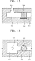
- FIGS. 15 and 16 respectively illustrate a cross-sectional view and a plan view of a structure of a droplet ejector according to a fifth embodiment of the present invention when no stimulus is applied to a volumetric structure;
- FIGS. 17 and 18 respectively illustrate a cross-sectional view and a plan view of a structure of a droplet ejector according to the fifth embodiment of the present invention when a stimulus is applied to a volumetric structure and the volumetric structure contracts;
- FIG. 19 is a graph of temperature versus volume of temperature sensitive hydrogen
- FIGS. 20A through 20D illustrate an operation of ejecting droplets using a droplet ejector according to the fifth embodiment of the present invention
- FIGS. 21 and 22 respectively illustrate a cross-sectional view and a plan view of a structure of an ink-jet printhead using a droplet ejector according to a sixth embodiment of the present invention
- FIG. 23 illustrates a cross-sectional view of a structure of an ink-jet printhead using a droplet ejector according to a seventh embodiment of the present invention.
- FIG. 24 illustrates a cross-sectional view of a structure of an ink-jet printhead using a droplet ejector according to an eighth embodiment of the present invention.
- FIGS. 6 and 7 respectively illustrate a cross-sectional view and a plan view of a structure of a droplet ejector according to a first embodiment of the present invention.
- a fluid flows to an inside of a fluid path formed by a nozzle 110 , a chamber 112 , and a channel 114 .
- the nozzle 110 through which droplets are ejected, is formed on one end of the fluid path and has a tapered shape such that a diameter thereof decreases as the nozzle 110 extends toward an outlet.
- the chamber 112 filled with the fluid to be ejected, is formed under the nozzle 110 , and the fluid is supplied to the chamber 112 through the channel 114 .
- a volumetric structure 120 formed of a material sensitive to an external stimulus, is formed in the chamber 112 filled with the fluid.
- the volumetric structure 120 is formed of a material that expands when a stimulus is applied thereto and contracts to an original state when the stimulus is removed.
- Stimulus sensitive hydrogel is used as the material.
- the stimulus sensitive hydrogel which is a water containing polymer network, is a material sensitive to temperature, pH, electrical field, light, or molecular concentration, and has a large volume variation.
- the volume of the stimulus sensitive hydrogel may increase from several times to several hundreds of times according to a composition thereof and a size of the external stimulus.
- the stimulus sensitive hydrogel is categorized into a variety of types depending on environmental factors to which hydrogel is sensitive, e.g., temperature sensitive hydrogel, pH-sensitive hydrogel, and electrical field sensitive hydrogel. Electrical field sensitive hydrogel is preferably used in the first embodiment.
- the electrical field sensitive hydrogel has a non-isotropic characteristic so that a volume variation in response to a stimulus is first generated toward a cathode.
- the electrical field sensitive hydrogel has a response time of a volume variation faster than other similar material.
- the volume variation amount and volume variation speed can be precisely controlled according to a voltage size and a pulse width.
- a volumetric structure formed of stimulus sensitive hydrogel as described above may be formed through photopatterning and photopolymerization. Specifically, a liquid pre-hydrogel mixture is filled in a fluid path, and light, for example, ultraviolet rays, is irradiated onto the liquid pre-hydrogel mixture through a photomask. Next, unpolymerized mixture liquid is removed such that the volumetric structure 120 having a desired shape and size is formed in the chamber 112 .
- the volumetric structure 120 when the volumetric structure 120 is formed of electrical field sensitive hydrogel, the volumetric structure 120 may be formed by radiating light having a strength of about 30 mW/cm 2 on a hydrogel pre-polymer mixture composed of acrylic acid and 2-hydroxyethyl methacrylate in a 1:4 molar ratio, ethylene glycol dimethacrylate 1.0 wt %, and 2,2-dimethoxy-2-phenyl-acetophenone 3.0 wt % through the photomask and cleaning the hydrogel pre-polymer mixture with methanol.
- a hydrogel pre-polymer mixture composed of acrylic acid and 2-hydroxyethyl methacrylate in a 1:4 molar ratio, ethylene glycol dimethacrylate 1.0 wt %, and 2,2-dimethoxy-2-phenyl-acetophenone 3.0 wt % through the photomask and cleaning the hydrogel pre-polymer mixture with methanol.
- volumetric structure 120 as illustrated in FIG. 6 has a columnar shape
- the volumetric structure 120 may have a hexahedral shape or a cylindrical shape in which a through hole is formed.
- a pair of first and second electrodes 130 a and 130 b are disposed above and below the volumetric structure 120 .
- the first and second electrodes 130 a and 130 b serve as a stimulus generator that applies a stimulus to the volumetric structure 120 .
- the first and second electrodes 130 a and 130 b apply an electrical field to the volumetric structure 120 .
- the first electrode 130 a is a cathode.
- a conductor for applying a voltage is connected to the first and second electrodes 130 a and 130 b.
- first and second electrodes 130 a and 130 b are respectively disposed above and below the volumetric structure 120
- the first and second electrodes 130 a and 130 b may be disposed at either side of the volumetric structure 120 .
- FIGS. 8A through 8D illustrate an operation of ejecting droplets using a droplet ejector when the volumetric structure 120 is formed of electrical field sensitive hydrogel.
- the volumetric structure 120 is initially maintained in a contracted state.
- FIG. 8B when a voltage is applied to the two electrodes 130 a and 130 b , an electrical field is generated between the two electrodes 130 a and 130 b . Due to the electrical field, the volumetric structure 120 expands. When the volumetric structure expands, a fluid in the chamber 112 is ejected through the nozzle 110 .
- the volumetric structure 120 contracts to an original state. Accordingly, the fluid to be ejected through the nozzle 110 is separated from the fluid in the nozzle 110 and is ejected as a droplet 150 by a contraction force.
- FIGS. 9 and 10 respectively illustrate a cross-sectional view and a plan view of a structure of an ink-jet printhead according to a second embodiment of the present invention.
- the ink-jet printhead includes a substrate 200 , a barrier layer 215 , a nozzle plate 225 , a volumetric structure 220 , and first and second electrodes 230 a and 230 b.
- a silicon wafer that is widely used to manufacture integrated circuits (ICs) may be used as the substrate 200 .
- a manifold 216 for supplying ink is formed on the substrate 200 , and the manifold 216 is in communication with an ink reservoir (not shown) in which ink is stored.
- the barrier layer 215 is formed on the substrate 200 , and an ink chamber 212 to be filled with ink to be ejected and an ink channel 214 for providing communication between the ink chamber 212 and the manifold 216 are formed on the barrier layer 215 .
- the ink channel 214 is a path through which ink is supplied from the manifold 216 to the ink chamber 212 .
- a plurality of ink chambers may be disposed in one row or two rows, or may be disposed in three or more rows to improve printing resolution.
- the volumetric structure 220 that expands when a stimulus is applied thereto is formed in the ink chamber 212 .
- the volumetric structure 220 is formed of electrical field sensitive hydrogel, which is a material that expands if an electrical field is applied to the volumetric structure 220 .
- volumetric structure 220 has a columnar shape
- the volumetric structure 220 may have a hexahedral shape or a cylindrical shape in which a through hole is formed.
- the second electrode 230 b of the first and second electrodes 230 a and 230 b for applying an electrical field to the volumetric structure 220 is formed between the substrate 200 and the barrier layer 215 .
- the second electrode 230 b is disposed below the volumetric structure 220 .
- a first insulating layer 202 is formed between the second electrode 230 b and the substrate 200 .
- a second insulating layer 204 for passivation and insulation of the second electrode 230 b is formed between the volumetric structure 220 and the second electrode 230 b.
- a nozzle plate 225 formed of a third insulating layer 223 and a metallic plate 224 is stacked on the barrier layer 215 .
- a nozzle 210 is formed in a position of the nozzle plate 225 , which corresponds to a center of the ink chamber 212 .
- the nozzle 210 has a tapered shape such that a diameter thereof decreases as the nozzle 210 extends toward an outlet.
- the first electrode 230 a is formed on a bottom surface of the nozzle plate 225 to surround the nozzle 210 .
- the first electrode 230 a applies an electrical field to the volumetric structure 220 together with the second electrode 230 b .
- the first electrode 230 a is a cathode.
- a conductor for applying a voltage is connected to the first and second electrodes 230 a and 230 b.
- the first insulating layer 202 , the second electrode 230 b , and the second insulating layer 204 are formed on the substrate 200 .
- the manifold to be in communication with an ink reservoir (not shown) is formed on the substrate 200 .
- the barrier layer 215 is stacked above the substrate 200 , and then, the ink chamber 212 and the ink channel 214 are formed on the barrier layer 215 .
- the ink channel 214 provides communication between the manifold 216 and the ink chamber 212 .
- the volumetric structure 220 is formed in the ink chamber 212 .
- a liquid pre-hydrogel mixture is filled in the ink chamber 212 , the ink channel 214 , and the manifold 216 , and light, for example, ultraviolet rays, is irradiated onto the liquid pre-hydrogel mixture through a photomask.
- unpolymerized mixture liquid is removed such that the volumetric structure 220 having a desired shape and size is formed in the chamber 212 .
- the nozzle plate 225 formed of the third insulating layer 223 and the metallic plate 224 is stacked on the barrier layer 215 , and then, the nozzle 210 and the first electrode 230 a for surrounding the nozzle 210 are formed.
- the nozzle 210 is in communication with the ink chamber 212 .
- the ink-jet printhead has a structure in which an electrode is disposed above and an electrode is disposed below a volumetric structure.
- the electrodes may be disposed in other positions with respect to the volumetric structure. An example thereof is shown in FIGS. 11 and 12 .
- a volumetric structure 320 is formed in the ink chamber 212 , and first and second electrodes 330 a and 330 b for applying an electrical field to the volumetric structure 320 are respectively disposed below either side of the volumetric structure 320 .
- the volumetric structure 320 formed in the ink chamber 212 may have a variety of shapes. An example thereof is shown in FIGS. 13 and 14 . Referring to FIGS. 13 and 14 , a volumetric structure 420 having a cylindrical shape, in which a through hole is formed, is formed in the ink chamber 212 . First and second electrodes 430 a and 430 b for applying an electrical field to the volumetric structure 420 are respectively disposed above and below the volumetric structure 420 .
- FIGS. 15 through 18 illustrate a droplet ejector according to the fifth embodiment of the present invention.
- FIGS. 15 and 16 respectively illustrate a cross-sectional view and a plan view of a structure of a droplet ejector when no stimulus is applied to a volumetric structure.
- FIGS. 17 and 18 respectively illustrate a cross-sectional view and a plan view of a structure of a droplet ejector when a stimulus is applied to a volumetric structure and the volumetric structure contracts.
- a fluid flows to an inside of a fluid path formed of a nozzle 510 , a chamber 512 , and a channel 514 .
- the nozzle 510 through which droplets are ejected is formed on one end of the fluid path and has a tapered shape such that a diameter thereof decreases as the nozzle 510 extends toward an outlet.
- the chamber 512 filled with the fluid to be ejected, is formed under the nozzle 510 , and the fluid is supplied to the chamber 512 through the channel 514 .
- a volumetric structure 520 that opens and closes the channel 514 due to a variation in a volume thereof is formed in the channel 514 .
- the volumetric structure 520 is a valve that controls the flow of the fluid flowing to the channel 514 and is formed of a material sensitive to an external stimulus.
- the volumetric structure 520 is formed of a material that contracts when a stimulus is applied thereto and expands to an original state when the stimulus is removed therefrom.
- Stimulus sensitive hydrogel is preferably used as the material.
- the stimulus sensitive hydrogel is a water containing polymer network and is categorized into a variety of types depending on environmental factors to which hydrogel is sensitive. Temperature sensitive hydrogel is preferably used in the fifth embodiment.
- the temperature of the temperature sensitive hydrogel When the temperature of the temperature sensitive hydrogel is higher than a lower critical solution temperature (LCST) of a polymer, the volume of the temperature sensitive hydrogel is reduced. When the temperature of temperature sensitive hydrogel is lower than the LCST of the polymer, the volume of the temperature sensitive hydrogel is increased. Specifically, if the temperature of temperature sensitive hydrogel is lower than the LCST of the polymer, a hydrogen bond between the polymer in the temperature sensitive hydrogel and a water molecule is formed, the water molecule is absorbed in the temperature sensitive hydrogel, and the temperature sensitive hydrogel expands.
- LCST critical solution temperature
- the temperature sensitive hydrogel has a volume variation from several times to several hundreds of times within a temperature range of about 15-30° C. A typical volume variation is shown in a graph of volume versus temperature in FIG. 19 .
- a structure formed of stimulus sensitive hydrogel may be formed through photopatterning and photopolymerization. Specifically, a liquid pre-hydrogel mixture is filled in a fluid path, and light, for example, ultraviolet rays, is irradiated onto the liquid pre-hydrogel mixture through a photomask. Next, unpolymerized mixture liquid is removed such that the volumetric structure 520 having a desired shape and size is formed in the channel 514 .
- the volumetric structure 520 when the volumetric structure 520 is formed of temperature sensitive hydrogel, the volumetric structure 520 may be formed using a precursor solution through photopolymerization. Specifically, the volumetric structure 520 may be formed by exposing light having a strength of about 15 mW/cm 2 on a precursor solution composed of 1.09 g N-isopropylacryl-amide, 62 mg N.N′-methylenebisacrylamide, 77 mg 2,2-dimethoxy-2-phenylaceto-phenone, 1.5 mL dimethylsulphoxide, and 0.5 mL deionized water through the photomask and cleaning the precursor solution with methanol.
- a precursor solution composed of 1.09 g N-isopropylacryl-amide, 62 mg N.N′-methylenebisacrylamide, 77 mg 2,2-dimethoxy-2-phenylaceto-phenone, 1.5 mL dimethylsulphoxide, and 0.5 mL deionized water through the photomask and cleaning the precursor solution with
- volumetric structure 520 is illustrated as having a columnar shape, the volumetric structure 520 may have a hexahedral shape. In addition, in the alternative to being formed in the channel 514 , the volumetric structure 520 may be formed in the nozzle 510 or in the chamber 512 .
- a resistance heating material 530 is disposed below the volumetric structure 520 .
- the resistance heating material 530 serves as a stimulus generator which applies a stimulus to the volumetric structure 520 .
- the resistance heating material 530 applies heat to the volumetric structure 520 .
- a conductor for applying a voltage is connected to the resistance heating material 530 .
- the resistance heating material 530 is disposed below the volumetric structure 520 , the resistance heating material 530 may be disposed at another location near the volumetric structure 520 , and a plurality of resistance heating materials may be included.
- the volumetric structure 520 when the resistance heating material 530 is not heated, as shown in FIGS. 15 and 16 , the volumetric structure 520 is initially maintained in an expanded state. As such, the channel 514 is closed. However, when the resistance heating material 530 is heated, as shown in FIGS. 17 and 18 , the volumetric structure 520 contracts, thereby opening the channel 514 .
- FIGS. 20A through 20D illustrate an operation of ejecting droplets using a droplet ejector when the volumetric structure 520 is formed of temperature sensitive hydrogel.
- the volumetric structure 520 is initially maintained in an expanded state.
- the channel 514 is closed, and the flow of a fluid (indicated by an arrow F) does not occur.
- the volumetric structure 520 cools and expands to the original state. As the volumetric structure 520 expands, the channel 514 is closed again. Thus, the fluid ejected through the nozzle 510 is separated from the fluid in the nozzle 510 and is ejected in a form of a droplet 550 .
- the channel 514 is completely closed, the droplet 550 is separated from the nozzle 510 , the movement of a meniscus is stabilized, and the volumetric structure 520 is restored to the original state.
- FIGS. 21 and 22 respectively illustrate a cross-sectional view and a plan view of a structure of an ink-jet printhead according to a sixth embodiment of the present invention.
- the ink-jet printhead includes a substrate 600 , a barrier layer 615 , a nozzle plate 625 , a volumetric structure 620 , and a resistance heating material 630 .
- a silicon wafer that is widely used to manufacture integrated circuits (ICs) may be used as the substrate 600 .
- a manifold 616 for supplying ink is formed on the substrate 600 .
- the manifold 616 is in communication with an ink reservoir (not shown) in which ink is stored.
- a barrier layer 615 is formed on the substrate 600 , and an ink chamber 612 to be filled with ink to be ejected and an ink channel 614 for providing communication between the ink chamber 612 and the manifold 616 are formed on the barrier layer 615 .
- the ink channel 614 is a path through which ink is supplied from the manifold 616 to the ink chamber 614 .
- a plurality of ink chambers may be disposed in one row or two rows, or may be disposed in three or more rows to improve printing resolution.
- the volumetric structure 620 that contracts when a stimulus is applied thereto is formed in the ink channel 614 .
- the volumetric structure 620 is formed of temperature sensitive hydrogel, which is a material that contracts if heat is applied to the volumetric structure 620 .
- volumetric structure 620 has a columnar shape
- the volumetric structure 620 may alternately have a hexahedral shape.
- the resistance heating material 630 for applying heat to the volumetric structure 620 is formed between the substrate 600 and the barrier layer 615 .
- the resistance heating material 630 is disposed below the volumetric structure 620 .
- the resistance heating material 630 may be disposed at another location near the volumetric structure 620 , and a plurality of resistance heating materials may be included.
- a conductor for applying a voltage is connected to the resistance heating material 630 .
- a first insulating layer 602 is formed between the resistance heating material 630 and the substrate 600 .
- a second insulating layer 604 for providing passivation and insulation of the resistance heating material 630 is formed between the resistance heating material 630 and the volumetric structure 620 .
- a nozzle plate 625 formed of a third insulating layer 623 and a metallic plate 624 is stacked on the barrier layer 615 .
- a nozzle 610 is formed in a position of the nozzle plate 625 , which corresponds to a center of the ink chamber 612 .
- the nozzle 610 has a tapered shape such that a diameter thereof decreases as the nozzle 610 extends toward an outlet.
- the temperature of the volumetric structure 620 increases, and the volumetric structure 620 contracts.
- ink flows from the ink reservoir (not shown) through the ink channel 614 , and ink is ejected in droplet form through the nozzle 610 .
- the voltage applied to the resistance heating material 630 is removed, the temperature of the volumetric structure 620 is reduced, and the volumetric structure 620 expands and is restored to the original state.
- the first insulating layer 602 , the resistance heating material 630 , and the second insulating layer 604 are formed on the substrate 600 .
- the manifold 616 to provide communication with an ink reservoir (not shown) is formed on the substrate 600 .
- the barrier layer 615 is stacked above the substrate 600 , and then, the ink chamber 612 and the ink channel 614 are formed on the barrier layer 615 .
- the ink channel 614 is in communication with the manifold 616 .
- the volumetric structure 620 is formed in the ink channel 614 .
- a liquid pre-hydrogel mixture is filled in the ink chamber 612 , the ink channel 614 , and the manifold 616 , and light, for example, ultraviolet rays, is irradiated onto the liquid pre-hydrogel mixture through the photomask.
- unpolymerized mixture liquid is removed such that the volumetric structure 620 having a desired shape and size is formed in the ink chamber 614 .
- the nozzle plate 625 formed of the third insulating layer 623 and the metallic plate 624 is stacked on the barrier layer 615 , and then, the nozzle 610 is formed.
- the nozzle 610 is in communication with the ink chamber 612 .
- the ink-jet printhead has a structure in which a volumetric structure is formed in an ink channel.
- the volumetric structure may be formed in either the nozzle or the ink chamber.
- a volumetric structure 720 is formed along an inner wall of the nozzle 610 , and a resistance heating material 730 is disposed to surround the volumetric structure 720 .
- the volumetric structure 720 expands and closes the nozzle 610 .
- the volumetric structure 720 contracts in a direction as illustrated by arrows. As such, ink droplets are ejected through a through hole formed in a center of the volumetric structure 720 .
- a volumetric structure 820 is formed in the ink chamber 612 , and a resistance heating material 830 is disposed below the volumetric structure 820 .
- the volumetric structure 820 expands and closes the nozzle 610 .
- the volumetric structure 820 contracts in a direction as illustrated by arrows. As such, the nozzle 610 is opened, and ink droplets are ejected through the nozzle 610 .
- the droplet ejector and the ink-jet printhead using the same according to the present invention have the following advantageous effects.
- the droplet ejector and the ink-jet printhead can be driven within a low temperature range of about 15-30° C., such that a lowering of an energy efficiency and a dissipating of a remaining thermal energy do not occur in a thermally driven ink-jet printhead.
- the droplet ejector and the ink-jet printhead have a simple structure, and the size thereof decreases, such that a nozzle becomes highly integrated.
- the composition of a material of a volumetric structure or stimulus conditions are adjusted, thereby varying a volume variation amount such that the size of ejected droplets is actively controlled.
- the position, size, and volume expansion ratio of the volumetric structure are properly adjusted, such that backflow during droplet ejection is reduced and a driving force is effectively utilized toward a nozzle.
- a temperature, an electrical field, and light are selected using an external stimulus to cause a volume variation, such that a variety of driving methods are used.
- the volumetric structure is formed in a chamber by a general semiconductor device process, such that a manufacturing process is simplified.
Abstract
Description
Claims (38)
Applications Claiming Priority (2)
| Application Number | Priority Date | Filing Date | Title |
|---|---|---|---|
| KR2003-4105 | 2003-01-21 | ||
| KR1020030004105A KR100571804B1 (en) | 2003-01-21 | 2003-01-21 | Liquid droplet ejector and ink jet printhead adopting the same |
Publications (2)
| Publication Number | Publication Date |
|---|---|
| US20040150694A1 US20040150694A1 (en) | 2004-08-05 |
| US7484833B2 true US7484833B2 (en) | 2009-02-03 |
Family
ID=32653304
Family Applications (1)
| Application Number | Title | Priority Date | Filing Date |
|---|---|---|---|
| US10/760,276 Expired - Fee Related US7484833B2 (en) | 2003-01-21 | 2004-01-21 | Droplet ejector and ink-jet printhead using the same |
Country Status (5)
| Country | Link |
|---|---|
| US (1) | US7484833B2 (en) |
| EP (1) | EP1442887B1 (en) |
| JP (1) | JP2004224053A (en) |
| KR (1) | KR100571804B1 (en) |
| DE (1) | DE602004020531D1 (en) |
Families Citing this family (12)
| Publication number | Priority date | Publication date | Assignee | Title |
|---|---|---|---|---|
| US7438395B2 (en) * | 2004-09-24 | 2008-10-21 | Brother Kogyo Kabushiki Kaisha | Liquid-jetting apparatus and method for producing the same |
| DE102004061731B4 (en) * | 2004-12-17 | 2006-12-14 | Technische Universität Dresden | Programmable microstamp |
| JP4682712B2 (en) * | 2005-06-13 | 2011-05-11 | ソニー株式会社 | Polymer actuator |
| KR100754392B1 (en) * | 2005-12-27 | 2007-08-31 | 삼성전자주식회사 | Ink path structure and inkjet printhead having the same |
| DE102006017482A1 (en) * | 2006-04-13 | 2007-10-18 | Technische Universität Chemnitz | Microfluidic actuator, actuator method and method of making a microactuator |
| US7883182B2 (en) * | 2006-04-21 | 2011-02-08 | Koninklijke Philips Electronics N.V. | Fluid ejection device for ink jet heads |
| JP5069186B2 (en) * | 2008-07-29 | 2012-11-07 | ソニー株式会社 | Droplet discharge head and droplet discharge apparatus |
| KR101490797B1 (en) * | 2008-09-09 | 2015-02-06 | 삼성전자주식회사 | Inkjet printhead |
| KR101097171B1 (en) | 2010-04-23 | 2011-12-21 | 제주대학교 산학협력단 | Electrostatic ink-jet head |
| CN103522761B (en) * | 2013-10-15 | 2015-04-22 | 中国电子科技集团公司第四十八研究所 | Ink-jetting printing head for super-thin grid solar cell |
| WO2015156820A1 (en) * | 2014-04-11 | 2015-10-15 | Hewlett-Packard Development Company, L. P. | Generate non-uniform electric field to maintain pigments in ink vehicle of printing fluid in nozzle region of printhead |
| KR102295924B1 (en) * | 2019-11-26 | 2021-08-31 | 세메스 주식회사 | Liquid drop discharging head and method for controlling discharging liquid drop |
Citations (12)
| Publication number | Priority date | Publication date | Assignee | Title |
|---|---|---|---|---|
| JPH01277839A (en) | 1988-04-30 | 1989-11-08 | Minolta Camera Co Ltd | Image forming body |
| JPH0299386A (en) | 1988-10-06 | 1990-04-11 | Ricoh Co Ltd | Image recording method and its apparatus |
| US5515085A (en) * | 1991-10-17 | 1996-05-07 | Minolta Camera Kabushiki Kaisha | Ink-jet type recorder |
| US5856837A (en) | 1993-08-23 | 1999-01-05 | Seiko Epson Corporation | Ink jet recording head with vibrating element having greater width than drive electrode |
| JPH11105276A (en) | 1997-09-30 | 1999-04-20 | Minolta Co Ltd | Ink-jet recording apparatus |
| KR100250358B1 (en) | 1997-12-24 | 2000-04-01 | 윤종용 | Apparatus for spout ink of inkjet printer |
| US6139132A (en) * | 1995-09-05 | 2000-10-31 | Seiko Epson Corporation | Ink jet recording head with nozzle communicating hole having smaller width than pressurizing chambers in direction of array of pressurizing chambers |
| US6293654B1 (en) | 1998-04-22 | 2001-09-25 | Hewlett-Packard Company | Printhead apparatus |
| US20020060704A1 (en) * | 2000-11-22 | 2002-05-23 | Brother Kogyo Kabushiki Kaisha | Ink-jet recording apparatus and method of manufacturing the same |
| US6406131B2 (en) | 1998-03-06 | 2002-06-18 | Eastman Kodak Company | Device for moving a fluid |
| US20030122895A1 (en) * | 2001-01-30 | 2003-07-03 | Torgerson Joseph M. | Ink jet printhead |
| US6726312B1 (en) * | 1999-10-12 | 2004-04-27 | Kabushiki Kaisha Giken | Ink jet head for use in a printer |
-
2003
- 2003-01-21 KR KR1020030004105A patent/KR100571804B1/en not_active IP Right Cessation
-
2004
- 2004-01-20 DE DE602004020531T patent/DE602004020531D1/en not_active Expired - Fee Related
- 2004-01-20 JP JP2004012390A patent/JP2004224053A/en active Pending
- 2004-01-20 EP EP04250271A patent/EP1442887B1/en not_active Expired - Fee Related
- 2004-01-21 US US10/760,276 patent/US7484833B2/en not_active Expired - Fee Related
Patent Citations (12)
| Publication number | Priority date | Publication date | Assignee | Title |
|---|---|---|---|---|
| JPH01277839A (en) | 1988-04-30 | 1989-11-08 | Minolta Camera Co Ltd | Image forming body |
| JPH0299386A (en) | 1988-10-06 | 1990-04-11 | Ricoh Co Ltd | Image recording method and its apparatus |
| US5515085A (en) * | 1991-10-17 | 1996-05-07 | Minolta Camera Kabushiki Kaisha | Ink-jet type recorder |
| US5856837A (en) | 1993-08-23 | 1999-01-05 | Seiko Epson Corporation | Ink jet recording head with vibrating element having greater width than drive electrode |
| US6139132A (en) * | 1995-09-05 | 2000-10-31 | Seiko Epson Corporation | Ink jet recording head with nozzle communicating hole having smaller width than pressurizing chambers in direction of array of pressurizing chambers |
| JPH11105276A (en) | 1997-09-30 | 1999-04-20 | Minolta Co Ltd | Ink-jet recording apparatus |
| KR100250358B1 (en) | 1997-12-24 | 2000-04-01 | 윤종용 | Apparatus for spout ink of inkjet printer |
| US6406131B2 (en) | 1998-03-06 | 2002-06-18 | Eastman Kodak Company | Device for moving a fluid |
| US6293654B1 (en) | 1998-04-22 | 2001-09-25 | Hewlett-Packard Company | Printhead apparatus |
| US6726312B1 (en) * | 1999-10-12 | 2004-04-27 | Kabushiki Kaisha Giken | Ink jet head for use in a printer |
| US20020060704A1 (en) * | 2000-11-22 | 2002-05-23 | Brother Kogyo Kabushiki Kaisha | Ink-jet recording apparatus and method of manufacturing the same |
| US20030122895A1 (en) * | 2001-01-30 | 2003-07-03 | Torgerson Joseph M. | Ink jet printhead |
Non-Patent Citations (2)
| Title |
|---|
| Patent Abstracts of Japan, vol. 0140, No. 50 (P-0998), Jan. 30, 1990) & JP 1 277839 (Nov. 8, 1989). |
| Patent Abstracts of Japan, vol. 0143, No. 05 (M-0992) Jun. 29, 1990 & JP 2 099 386 A (Apr. 11, 1990). |
Also Published As
| Publication number | Publication date |
|---|---|
| EP1442887B1 (en) | 2009-04-15 |
| US20040150694A1 (en) | 2004-08-05 |
| JP2004224053A (en) | 2004-08-12 |
| DE602004020531D1 (en) | 2009-05-28 |
| KR100571804B1 (en) | 2006-04-17 |
| EP1442887A1 (en) | 2004-08-04 |
| KR20040067124A (en) | 2004-07-30 |
Similar Documents
| Publication | Publication Date | Title |
|---|---|---|
| AU752431B2 (en) | Apparatus and method for using bubble as virtual valve in microinjector to eject fluid | |
| US6692112B2 (en) | Monolithic ink-jet printhead | |
| US7334335B2 (en) | Method of manufacturing a monolithic ink-jet printhead | |
| US7368063B2 (en) | Method for manufacturing ink-jet printhead | |
| US7484833B2 (en) | Droplet ejector and ink-jet printhead using the same | |
| US7926177B2 (en) | Method of forming hydrophobic coating layer on surface of nozzle plate of inkjet printhead | |
| US7104632B2 (en) | Monolithic ink-jet printhead and method for manufacturing the same | |
| US7758165B2 (en) | Ink-jet printhead and manufacturing method thereof | |
| KR20040034250A (en) | Monolithic ink jet printhead having taper shaped nozzle and method of manufacturing thereof | |
| US20230112999A1 (en) | Microfluidic device for continuous ejection of fluids, in particular for ink printing, and related manufacturing process | |
| JPH05220961A (en) | Directivity of thermal ink jet converter by front face metal spray | |
| US5461406A (en) | Method and apparatus for elimination of misdirected satellite drops in thermal ink jet printhead | |
| US7367656B2 (en) | Ink-jet printhead and method for manufacturing the same | |
| US20070220723A1 (en) | Method for manufacturing inkjet head | |
| KR100477707B1 (en) | Method of manufacturing Monolithic inkjet printhead | |
| JP3533205B2 (en) | Micro droplet generating apparatus and method for manufacturing the same | |
| US7018019B2 (en) | Ink-jet printhead and method for manufacturing the same | |
| US9004651B2 (en) | Thermo-pneumatic actuator working fluid layer | |
| KR100477704B1 (en) | Monolithic inkjet printhead and method of manufacturing thereof | |
| KR20050014130A (en) | Ink-jet printhead driven piezoelectrically and electrostatically and method for manufacturing method thereof | |
| US9004652B2 (en) | Thermo-pneumatic actuator fabricated using silicon-on-insulator (SOI) |
Legal Events
| Date | Code | Title | Description |
|---|---|---|---|
| AS | Assignment |
Owner name: SAMSUNG ELECTRONICS CO., LTD., KOREA, REPUBLIC OF Free format text: ASSIGNMENT OF ASSIGNORS INTEREST;ASSIGNORS:KIM, MIN-SOO;LEE, SUK-HAN;OH, YONG-SOO;AND OTHERS;REEL/FRAME:014930/0114 Effective date: 20040119 |
|
| FEPP | Fee payment procedure |
Free format text: PAYOR NUMBER ASSIGNED (ORIGINAL EVENT CODE: ASPN); ENTITY STATUS OF PATENT OWNER: LARGE ENTITY |
|
| STCF | Information on status: patent grant |
Free format text: PATENTED CASE |
|
| FEPP | Fee payment procedure |
Free format text: PAYER NUMBER DE-ASSIGNED (ORIGINAL EVENT CODE: RMPN); ENTITY STATUS OF PATENT OWNER: LARGE ENTITY Free format text: PAYOR NUMBER ASSIGNED (ORIGINAL EVENT CODE: ASPN); ENTITY STATUS OF PATENT OWNER: LARGE ENTITY |
|
| FPAY | Fee payment |
Year of fee payment: 4 |
|
| REMI | Maintenance fee reminder mailed | ||
| FPAY | Fee payment |
Year of fee payment: 8 |
|
| SULP | Surcharge for late payment |
Year of fee payment: 7 |
|
| AS | Assignment |
Owner name: S-PRINTING SOLUTION CO., LTD., KOREA, REPUBLIC OF Free format text: ASSIGNMENT OF ASSIGNORS INTEREST;ASSIGNOR:SAMSUNG ELECTRONICS CO., LTD;REEL/FRAME:041852/0125 Effective date: 20161104 |
|
| AS | Assignment |
Owner name: HP PRINTING KOREA CO., LTD., KOREA, REPUBLIC OF Free format text: CHANGE OF NAME;ASSIGNOR:S-PRINTING SOLUTION CO., LTD.;REEL/FRAME:047370/0405 Effective date: 20180316 |
|
| AS | Assignment |
Owner name: HP PRINTING KOREA CO., LTD., KOREA, REPUBLIC OF Free format text: CORRECTIVE ASSIGNMENT TO CORRECT THE DOCUMENTATION EVIDENCING THE CHANGE OF NAME PREVIOUSLY RECORDED ON REEL 047370 FRAME 0405. ASSIGNOR(S) HEREBY CONFIRMS THE CHANGE OF NAME;ASSIGNOR:S-PRINTING SOLUTION CO., LTD.;REEL/FRAME:047769/0001 Effective date: 20180316 |
|
| AS | Assignment |
Owner name: HP PRINTING KOREA CO., LTD., KOREA, REPUBLIC OF Free format text: CHANGE OF LEGAL ENTITY EFFECTIVE AUG. 31, 2018;ASSIGNOR:HP PRINTING KOREA CO., LTD.;REEL/FRAME:050938/0139 Effective date: 20190611 |
|
| AS | Assignment |
Owner name: HEWLETT-PACKARD DEVELOPMENT COMPANY, L.P., TEXAS Free format text: CONFIRMATORY ASSIGNMENT EFFECTIVE NOVEMBER 1, 2018;ASSIGNOR:HP PRINTING KOREA CO., LTD.;REEL/FRAME:050747/0080 Effective date: 20190826 |
|
| FEPP | Fee payment procedure |
Free format text: MAINTENANCE FEE REMINDER MAILED (ORIGINAL EVENT CODE: REM.); ENTITY STATUS OF PATENT OWNER: LARGE ENTITY |
|
| LAPS | Lapse for failure to pay maintenance fees |
Free format text: PATENT EXPIRED FOR FAILURE TO PAY MAINTENANCE FEES (ORIGINAL EVENT CODE: EXP.); ENTITY STATUS OF PATENT OWNER: LARGE ENTITY |
|
| STCH | Information on status: patent discontinuation |
Free format text: PATENT EXPIRED DUE TO NONPAYMENT OF MAINTENANCE FEES UNDER 37 CFR 1.362 |
|
| FP | Lapsed due to failure to pay maintenance fee |
Effective date: 20210203 |