US7489464B1 - Servo writing a disk drive using a secondary actuator to control skew angle - Google Patents
Servo writing a disk drive using a secondary actuator to control skew angle Download PDFInfo
- Publication number
- US7489464B1 US7489464B1 US11/050,508 US5050805A US7489464B1 US 7489464 B1 US7489464 B1 US 7489464B1 US 5050805 A US5050805 A US 5050805A US 7489464 B1 US7489464 B1 US 7489464B1
- Authority
- US
- United States
- Prior art keywords
- disk
- head
- write
- servo
- read
- Prior art date
- Legal status (The legal status is an assumption and is not a legal conclusion. Google has not performed a legal analysis and makes no representation as to the accuracy of the status listed.)
- Expired - Fee Related, expires
Links
- 238000000034 method Methods 0.000 claims abstract description 37
- 230000008859 change Effects 0.000 claims description 5
- 230000008569 process Effects 0.000 description 8
- 238000011084 recovery Methods 0.000 description 8
- 238000004519 manufacturing process Methods 0.000 description 7
- 238000012545 processing Methods 0.000 description 5
- 238000005070 sampling Methods 0.000 description 5
- 239000000725 suspension Substances 0.000 description 5
- 238000013459 approach Methods 0.000 description 4
- 230000000644 propagated effect Effects 0.000 description 4
- 230000001902 propagating effect Effects 0.000 description 4
- 230000007704 transition Effects 0.000 description 4
- 238000010586 diagram Methods 0.000 description 3
- 230000000694 effects Effects 0.000 description 3
- 230000007423 decrease Effects 0.000 description 2
- 230000004044 response Effects 0.000 description 2
- 230000001360 synchronised effect Effects 0.000 description 2
- 238000010420 art technique Methods 0.000 description 1
- 230000001427 coherent effect Effects 0.000 description 1
- 230000001351 cycling effect Effects 0.000 description 1
- 230000003247 decreasing effect Effects 0.000 description 1
- 230000001934 delay Effects 0.000 description 1
- 238000013461 design Methods 0.000 description 1
- 230000004907 flux Effects 0.000 description 1
- 238000003780 insertion Methods 0.000 description 1
- 230000037431 insertion Effects 0.000 description 1
- 230000000737 periodic effect Effects 0.000 description 1
- 238000003825 pressing Methods 0.000 description 1
Images


Classifications
-
- G—PHYSICS
- G11—INFORMATION STORAGE
- G11B—INFORMATION STORAGE BASED ON RELATIVE MOVEMENT BETWEEN RECORD CARRIER AND TRANSDUCER
- G11B5/00—Recording by magnetisation or demagnetisation of a record carrier; Reproducing by magnetic means; Record carriers therefor
- G11B5/48—Disposition or mounting of heads or head supports relative to record carriers ; arrangements of heads, e.g. for scanning the record carrier to increase the relative speed
- G11B5/4806—Disposition or mounting of heads or head supports relative to record carriers ; arrangements of heads, e.g. for scanning the record carrier to increase the relative speed specially adapted for disk drive assemblies, e.g. assembly prior to operation, hard or flexible disk drives
- G11B5/4826—Mounting, aligning or attachment of the transducer head relative to the arm assembly, e.g. slider holding members, gimbals, adhesive
-
- G—PHYSICS
- G11—INFORMATION STORAGE
- G11B—INFORMATION STORAGE BASED ON RELATIVE MOVEMENT BETWEEN RECORD CARRIER AND TRANSDUCER
- G11B5/00—Recording by magnetisation or demagnetisation of a record carrier; Reproducing by magnetic means; Record carriers therefor
- G11B5/48—Disposition or mounting of heads or head supports relative to record carriers ; arrangements of heads, e.g. for scanning the record carrier to increase the relative speed
- G11B5/54—Disposition or mounting of heads or head supports relative to record carriers ; arrangements of heads, e.g. for scanning the record carrier to increase the relative speed with provision for moving the head into or out of its operative position or across tracks
- G11B5/55—Track change, selection or acquisition by displacement of the head
- G11B5/5521—Track change, selection or acquisition by displacement of the head across disk tracks
- G11B5/5552—Track change, selection or acquisition by displacement of the head across disk tracks using fine positioning means for track acquisition separate from the coarse (e.g. track changing) positioning means
-
- G—PHYSICS
- G11—INFORMATION STORAGE
- G11B—INFORMATION STORAGE BASED ON RELATIVE MOVEMENT BETWEEN RECORD CARRIER AND TRANSDUCER
- G11B5/00—Recording by magnetisation or demagnetisation of a record carrier; Reproducing by magnetic means; Record carriers therefor
- G11B5/48—Disposition or mounting of heads or head supports relative to record carriers ; arrangements of heads, e.g. for scanning the record carrier to increase the relative speed
- G11B5/58—Disposition or mounting of heads or head supports relative to record carriers ; arrangements of heads, e.g. for scanning the record carrier to increase the relative speed with provision for moving the head for the purpose of maintaining alignment of the head relative to the record carrier during transducing operation, e.g. to compensate for surface irregularities of the latter or for track following
- G11B5/596—Disposition or mounting of heads or head supports relative to record carriers ; arrangements of heads, e.g. for scanning the record carrier to increase the relative speed with provision for moving the head for the purpose of maintaining alignment of the head relative to the record carrier during transducing operation, e.g. to compensate for surface irregularities of the latter or for track following for track following on disks
- G11B5/59633—Servo formatting
- G11B5/59638—Servo formatting apparatuses, e.g. servo-writers
Definitions
- the present invention relates to disk drives. More particularly, the present invention relates to servo writing a disk drive using a secondary actuator to control skew angle.
- Disk drives for computer systems comprise a disk for storing data and a head actuated radially over the disk for writing data to and reading data from the disk.
- the head is connected to the distal end of an actuator arm which is rotated about a pivot by a rotary actuator (e.g., a voice coil motor (VCM)).
- VCM voice coil motor
- the disk is typically divided into a number of concentric, radially spaced tracks, where each track is divided into a number of data sectors.
- the disk is typically accessed a data sector at a time by positioning the head over the track which comprises the target data sector.
- transitions e.g., magnetic transitions
- a closed loop servo system typically performs the seeking and tracking operations by controlling the rotary actuator in response to position information generated from the head.
- a well known technique for generating the head position control information is to record servo information in servo sectors disbursed circumferentially about the disk, “embedded” with the data sectors. This is illustrated in FIG. 1 which shows a disk 2 comprising a number of concentric data tracks 4 and a number of embedded servo sectors 6 0 - 6 N .
- Each servo sector 6 i comprises a preamble 8 , a sync mark 10 , servo data 12 , and servo bursts 14 .
- the preamble 8 comprises a periodic pattern which allows proper gain adjustment and timing synchronization of the read signal
- the sync mark 10 comprises a special pattern for symbol synchronizing to the servo data 12 .
- the servo data 12 comprises identification information, such as sector identification data and a track address.
- the servo control system reads the track address during seeks to derive a coarse position for the head with respect to the target track.
- the track addresses are recorded using a phase coherent Gray code so that the track addresses can be accurately detected when the head is flying between tracks.
- the servo bursts 14 in the servo sectors 6 comprise groups of consecutive transitions (e.g., A, B, C and D bursts) which are recorded at precise intervals and offsets with respect to the track centerline. Fine head position control information is derived from the servo bursts 14 for use in centerline tracking while writing data to and reading data from the target track.
- the embedded servo sectors 6 are written to the disk 2 as part of the manufacturing process.
- an external servo writer has been employed which writes the embedded servo sectors 6 to the disks by processing each head disk assembly (HDA) in an assembly line fashion.
- the external servo writers employ very precise head positioning mechanics, such as a laser interferometer, for positioning the head at precise radial locations with respect to previously servo-written tracks so as to achieve very high track densities.
- U.S. Pat. No. 5,949,603 discloses a technique for self-servo writing wherein the servo sectors are written relative to clock data disbursed around the disk and propagated from track to track.
- the clock data is first written to a “seed” track (e.g., at the inner diameter of the disk) from which the clock data as well as the servo sectors are propagated to the remaining tracks.
- the head is positioned over the seed track and, while reading the clock data in the seed track, the head is moved away from the seed track until the amplitude of the read signal decreases to some predetermined level.
- the clock data and servo sectors are written to the first track adjacent to the seed track. This process is repeated for the next and subsequent tracks until the embedded servo sectors have been written over the entire surface of the disk.
- MR magnetoresistive
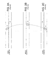
- FIGS. 2A-2C illustrate another problem that manifests when servo writing the disk 2 using perpendicular magnetic recording.
- the skew angle of the head's write pole 16 as it approaches the outer diameter causes the inner corner of the write pole 16 to “swing out” and overwrite a band 18 of the previously written servo data.
- the servo sectors 6 0 - 6 N from the outer diameter of the disk ( FIG. 2C ) toward the inner diameter of the disk ( FIG.
- the skew angle of the head's write pole 16 as it approaches the inner diameter causes the inner corner of the write pole 16 to “swing out” and overwrite a band 20 of the previously written servo data.
- the overwritten band ( 18 or 20 ) creates a “seam” between adjacent servo sectors, as well as a seam within each servo sector (including the servo bursts 14 ) if multiple revolutions are used to “stitch” together each servo sector 6 i .
- U.S. Pat. No. 6,504,675 discloses a disk drive wherein the write pole has a trapezoidal shape in order to reduce the overwrite problem caused by the skew effect.
- the geometry of the trapezoidal shape varies between each disk drive due to tolerances in manufacturing the head, resulting in undesirable seams in the servo wedges for some percentage of the disk drives.
- manufacturing the write pole with a trapezoidal shape increases the manufacturing cost of the head, as well as reduces the surface area of the write pole leading to an undesirable decrease in the strength of the magnetic write flux.
- the present invention may be regarded as a disk drive comprising a disk, an actuator arm, and a head coupled to a distal end of the actuator arm, wherein the head comprises a read element and a write element.
- a voice coil motor (VCM) rotates the actuator arm about a pivot to actuate the head radially over the disk, and a secondary actuator adjusts a skew angle of the head.
- Control circuitry writes a plurality of servo sectors to the disk to define a plurality of data tracks.
- the control circuitry controls the VCM to move the head radially across the disk, and controls the secondary actuator to achieve a desired skew angle for the head while using the write element to write the servo sectors to the disk.
- control circuitry controls the secondary actuator so that the write element leads the read element as the head moves radially across the disk.
- the disk controller uses the read element to read previously written servo data in a first servo track to generate servo control information for controlling the VCM to position the write element over a second servo track.
- the head is coupled to the actuator arm by a suspension and the secondary actuator rotates the suspension about a pivot.
- control circuitry calibrates a control signal applied to the secondary actuator and a corresponding change in the skew angle of the head.
- the read element is radially offset from the write element, and in one embodiment, the control circuitry measures the radial offset between the read element and the write element.
- control circuitry adjusts a control signal applied to the secondary actuator to achieve a target radial offset between the read element and the write element.
- the read element is separated from the write element along the length of a servo track forming a read/write gap, and the control circuitry adjusts a control signal applied to the secondary actuator to achieve a target read/write gap.
- control circuitry adjusts a control signal applied to the secondary actuator to maintain a substantially constant skew angle while moving the head radially across the disk to achieve a substantially constant track density. In another embodiment, the control circuitry adjusts a control signal applied to the secondary actuator to vary the skew angle while moving the head radially across the disk to achieve a variable track density.
- the invention may also be regarded as a method of servo writing a plurality of servo sectors to a disk of a disk drive to define a plurality of data tracks.
- the disk drive comprises the disk, an actuator arm, and a head coupled to a distal end of the actuator arm, wherein the head comprises a read element and a write element.
- a voice coil motor (VCM) rotates the actuator arm about a pivot to actuate the head radially over the disk, and a secondary actuator adjusts a skew angle for the head while using the write element to write the servo sectors to the disk.
- VCM voice coil motor
- FIG. 1 shows a prior art format for a disk comprising a plurality of concentric, radially-spaced data tracks, and a plurality of embedded servo sectors.
- FIGS. 2A-2C illustrate a problem when servo writing a disk using perpendicular magnetic recording wherein the skew angle of the head causes the write element to overwrite previously written servo data.
- FIG. 3A shows a disk drive according to an embodiment of the present invention comprising a voice coil motor (VCM) actuator for actuating the head radially over the disk and a secondary actuator for adjusting a skew angle of the head while writing the servo sectors to the disk.
- VCM voice coil motor
- FIG. 3B shows a head according to an embodiment of the present invention comprising a read element and a write element which are offset radially and separated by a read/write gap.
- FIG. 3C shows an embodiment of the present invention wherein an external servo writer controls the secondary actuator to adjust the skew angle of the head while writing the servo sectors to the disk.
- FIG. 4 is a flow diagram according to an embodiment of the present invention for writing the servo sectors to the disk.
- FIG. 5 illustrates how the skew angle of the head is controlled so that the write element leads the read element while self-servo writing the servo sectors from the inner to outer diameter of the disk using propagation.
- FIGS. 6A-6C illustrate how the read/write gap between the read and write elements changes relative to the skew angle of the head.
- FIG. 7 illustrates a technique according to an embodiment of the present invention for measuring the read/write gap between the read and write element which provides feedback for controlling the desired skew angle for the head.
- FIG. 8 shows circuitry according to an embodiment of the present invention for measuring the read/write gap between the read and write element.
- FIG. 9 illustrates an embodiment of the present invention wherein the skew angle of the head is adjusted to achieve a variable track density.
- FIG. 3A shows a disk drive comprising a disk 22 , an actuator arm 24 , and a head 26 coupled to a distal end of the actuator arm 24 , wherein the head 26 comprises a read element 28 and a write element 30 ( FIG. 3B ).
- a voice coil motor (VCM) 32 rotates the actuator arm 24 about a pivot to actuate the head 26 radially over the disk 22 , and a secondary actuator 34 adjusts a skew angle of the head 26 .
- Control circuitry 36 writes a plurality of servo sectors 38 0 - 38 N to the disk 22 to define a plurality of data tracks 40 .
- the control circuitry 36 controls the VCM 32 to move the head 26 radially across the disk 22 , and controls the secondary actuator 34 to achieve a desired skew angle for the head 26 while using the write element 30 to write the servo sectors 38 0 - 38 N to the disk 22 .
- the disk drive in the embodiment of FIG. 3A comprises a read channel 42 for processing the read signal 44 emanating from the head 26 .
- the read channel 42 comprises suitable circuitry for processing the read signal 44 to generate a position error signal (PES) representing the actual radial location of the head 26 .
- PES position error signal
- the PES is processed by the control circuitry 36 to generate a VCM control signal 46 applied to the VCM 32 in order to maintain the head 26 over the target radial location while writing the servo sectors 38 0 - 38 N to the disk 22 .
- the read channel 42 may also comprise circuitry for measuring the actual skew angle of the head 26 which is processed as feedback by the control circuitry 36 to generate a control signal 48 applied to the secondary actuator 34 to maintain a target skew angle for the head 26 .
- an external servo writer 50 controls the secondary actuator 34 to achieve a desired skew angle for the head 26 while using the write element 30 to write the servo sectors 38 0 - 38 N to the disk 22 .
- the external servo writer 50 inserts a push pin through an aperture of the head disk assembly (HDA) 52 of the disk drive for controlling movement of the actuator arm 24 and controls the secondary actuator 34 through an electrical interface.
- the external servo writer 50 may control movement of the actuator arm 24 by controlling the VCM 32 through an electrical interface.
- the external servo writer 50 comprises an external motion sensor, such as a laser interferometer, for detecting the radial location of the head 26 (feedback), and in an alternative embodiment the external servo writer 50 processes the read signal 44 emanating from the head 26 to detect the radial location of the head 26 .
- the external servo writer 50 may also determine the skew angle of the head 26 using an external motion sensor or by processing the read signal 44 .
- FIG. 4 is a flow diagram according to an embodiment of the present invention for writing the servo sectors 38 0 - 38 N to the disk 22 .
- the flow diagram may be executed by the control circuitry 36 internal to the disk drive during a self-servo writing operation, or executed by the external servo writer 50 of FIG. 3C .
- the head 26 is positioned over a first servo track (e.g., using the VCM 32 or a push pin of the external servo writer 50 ), and at step 56 a control signal is applied to the secondary actuator 34 to maintain a target skew angle for the head 26 .
- step 58 the servo sectors are written to the disk 22 for the current servo track, at step 60 the head 26 is moved radially to the next servo track, and at step 62 the control signal applied to the secondary actuator 34 is adjusted (to maintain the target skew angle). Steps 58 - 62 are repeated until at step 64 the entire disk drive has been servo written.
- FIG. 5 illustrates how the secondary actuator 34 is controlled to maintain a target skew angle for the head 26 as the actuator arm 24 is rotated to position the head radially over the disk 22 (e.g., from the inner diameter to the outer diameter) during the servo writing operation.
- the servo sectors are written by propagating the servo data (and timing data) from track to track.
- a seed track is first written to the disk, for example, using an external servo writer or while pressing the actuator arm 24 against a crash stop.
- the read element 28 is then used to read the seed track while the write element 30 writes the servo data (and timing data) to the next servo track. This processes is then repeated for the next servo track until the servo data (and timing data) are propagated across the surface of the disk 22 .
- adjusting the skew angle of the head 26 creates a radial offset between the read element 28 and the write element 30 which allows the write element 30 to write the servo data to the next servo track while the read element 28 reads the servo data from the previously written servo track.
- the secondary actuator 34 is controlled so that the write element 30 leads the read element 28 as the head 26 moves radially across the disk 22 to facilitate propagating the servo data.
- the servo sectors are propagated from the inner diameter to the outer diameter of the disk 22 (right to left) and the secondary actuator 34 controlled so that the write element 30 always leads the read element 28 .
- adjusting the skew angle of the head 26 creates an offset between the read element 28 and the write element 30 that is less than the width of a servo track.
- the position error signal (PES) for controlling the VCM 32 is generated by moving the head 26 radially until the amplitude of the read signal 44 reaches a target amplitude.
- adjusting the skew angle of the head 26 creates an offset between the read element 28 and the write element 30 that equals the width of a servo track (or integer multiple thereof).
- This embodiment allows the read element 28 to read the center of a previously written servo track while writing the servo sectors to the next servo track so that the PES for controlling the VCM 32 can be generated by processing the servo bursts in the previously written servo track using a conventional servo algorithm.
- any suitable secondary actuator 34 may be employed that provides the necessary stroke to achieve the desired skew angle for the head 26 .
- the secondary actuator preferably exhibits a DC response so that the target skew angle can be maintained while writing the servo sectors to the disk.
- the secondary actuator 34 is electro-magnetic such as the secondary actuator disclosed in U.S. Pat. No. 6,636,388 the disclosure of which is incorporated herein by reference.
- the secondary actuator 34 may be configured in any suitable manner to achieve the desired skew angle for the head 26 .
- the head 26 is coupled to the actuator arm 24 by a suspension, and the secondary actuator 34 rotates the suspension about a pivot.
- the head 26 is coupled to the suspension through a gimbal which is rotated about a pivot by the secondary actuator.
- the read element 28 is radially offset from the write element 30 when the skew angle of the head 26 is zero.
- the offset may be by design or due to tolerances in manufacturing the head 26 which is typical for magnetoresistive (MR) heads. Since the radial offset between the read element 28 and write element 30 is modified by adjusting the skew angle of the head 26 , in one embodiment the inherent radial offset between the read element 28 and write element 30 is first measured to determine the appropriate skew angle that will achieve the target radial offset. Any suitable technique may be employed for measuring the inherent radial offset between the read and write element, such as the technique disclosed in U.S. Pat. No. 6,317,285 the disclosure of which is incorporated herein by reference.
- control signal applied to the secondary actuator 34 and the corresponding change in the skew angle of the head 26 is calibrated for each disk drive.
- the skew angle may be measured using any suitable technique, including a motion sensor integrated into an external servo writer.
- the read signal 44 generated by the head 26 is evaluated to measure the skew angle as described below with reference to FIGS. 6A-6C .
- the skew angle at the outer diameter and inner diameter of the disk due to the stroke of the actuator arm 24 is measured.
- the control signal applied to the secondary actuator 34 is then adjusted open loop during the servo writing process to account for the change in skew angle due to the changing radial location of the head 26 .
- the skew angle of the head 26 is measured during the servo writing process to generate a feedback signal that is compared to a target skew angle.
- the difference between the measured and target skew angle is used to adjust the control signal 48 applied to the secondary actuator 34 in a closed loop system.
- Any suitable technique may be employed to measure the skew angle for generating the feedback signal.
- the read element 28 is separated from the write element 30 along the length of a servo track forming a read/write (R/W) gap ( FIG. 3B ).
- R/W read/write
- the R/W gap changes as a function of the skew angle of the head 26 ; accordingly, the skew angle can be estimated by measuring the R/W gap.
- the control signal applied to the secondary actuator 34 is adjusted to achieve a target read/write gap in order to achieve the target skew angle.
- FIG. 7 illustrates a suitable technique for measuring the R/W gap by measuring write/read delays relative to a first and second sync mark.
- the first sync mark 66 is part of a servo sector 38
- the second sync mark 68 is written a predetermined interval following the servo sector forming a gap 70 .
- a first preamble 72 precedes the first sync mark 66 and a second preamble 74 precedes the second sync mark 68 .
- FIG. 7 illustrates a suitable technique for measuring the R/W gap by measuring write/read delays relative to a first and second sync mark.
- the disk 22 is rotating such that the head 26 is effectively moving from left to right over the track, and in this configuration, the read element 28 is “in front” of the write element 30 such that the write element 30 “lags” the reader 28 by the R/W gap as the track passes under the head 26 .
- the read element 28 detects the first sync mark 66 and the second sync mark 68 , the write delay and the read delay are measured relative to the read element 28 .
- the write delay begins at the end of the first sync mark 66 (relative to the read element 28 ) and ends after writing the second sync mark 68 (when the write element 30 has finished writing the second sync mark 68 ).
- the read delay begins at the end of the first sync mark 66 and ends when the read element 28 reaches the end of the second sync mark 68 .
- the R/W gap is estimated by subtracting the measured read delay from the measured write delay.
- FIG. 8 shows circuitry according to an embodiment for measuring the R/W gap which may be implemented within the disk drive or alternatively in the external servo writer 50 .
- the circuitry comprises a sampling device 76 for sampling the read signal 44 emanating from the head 26 to generate a sequence of signal samples 78 .
- Timing recovery 80 processes the signal samples 78 to generate a timing control signal 82 applied to an oscillator 84 .
- the oscillator 84 outputs a clock 86 used to control the frequency of the sampling device 76 .
- the timing recovery 80 adjusts the frequency of the clock 86 until the read signal 44 is sampled synchronously (thereby synchronizing the cycling of the clock 86 when reading the first preamble 72 and the second preamble 74 ).
- a sequence detector 88 processes the signal samples 78 to detect an estimated sequence 90
- a sync mark detector 92 evaluates the estimated sequence 90 to detect the first sync mark 66 and the second sync mark 68 .
- the timing recovery 80 generates a control signal 94 for enabling the sync mark detector 92 when the sync marks are expected to occur in the estimated sequence 90 .
- the sync mark detector 92 During a first revolution when writing the second preamble 74 and second sync mark 68 to measure the write delay, the sync mark detector 92 generates a control signal 96 when the first sync mark 66 is detected. Timing circuitry 98 responds to the sync mark detect signal 96 by enabling a write gate 100 at the appropriate time.
- the write gate 100 enables write circuitry 102 to start writing the second preamble 74 and second sync mark 68 .
- the timing circuitry 98 comprises a write delay counter 104 for counting a number of the clock cycles 86 relative to the first sync mark 66 until the second sync mark 68 has been written to the disk 22 .
- the sync mark detector 92 During a second revolution when reading the second preamble 74 and second sync mark 68 to measure the read delay, the sync mark detector 92 generates a control signal 96 when the first sync mark 66 is detected.
- the timing circuitry 98 responds to the sync mark detect signal 96 by enabling a read delay counter 106 and enabling a read gate 108 over line 110 at the appropriate time relative to the clock 86 as the head 26 approaches the second preamble 74 .
- the read gate 108 enables the timing recovery 80 to start synchronizing to the second preamble 74 , and the timing recovery 80 enables the sync mark detector 92 as the head 26 approaches the second sync mark 68 .
- the read delay counter 106 counts a number of the clock cycles 86 until the second sync mark 68 is detected by the sync mark detector 92 .
- the contents of the write delay counter 104 and read delay counter 106 represents the write delay and read delay for estimating the R/W gap.
- the clock 86 is used to clock the write circuitry 102 when writing the second preamble 74 and second sync mark 68 to the disk 22 .
- the second preamble 74 and second sync mark 68 are written substantially synchronous (in frequency and phase) with the first preamble 72 and the first sync mark 66 .
- a separate write clock is used to clock the write circuitry 102 while writing the second preamble 74 and second sync mark 68 to the disk 22 .
- the embodiment of FIG. 8 generates the clock 86 by synchronously sampling the read signal 44 , that is, by adjusting the frequency of the clock 86 until the sampling device 76 samples the read signal 44 synchronously.
- interpolated timing recovery is employed wherein the read signal 44 is sampled asynchronously and synchronous signal samples derived from the asynchronous signal samples.
- the interpolated timing recovery also comprises circuitry for generating the clock 86 synchronously for writing/reading the second preamble 74 and second sync mark 68 .
- the details of interpolated timing recovery are well known and not disclosed herein so as not to obscure the embodiments of the present invention.
- control signal applied to the secondary actuator 34 is adjusted to maintain a substantially constant skew angle while moving the head 26 radially across the disk 22 to achieve a substantially constant track density.
- control signal applied to the secondary actuator 34 is adjusted to vary the skew angle while moving the head radially across the disk to achieve a variable track density.
- FIG. 9 shows an example embodiment wherein the track density is decreased near the outer diameter of the disk 22 where servo errors (track misregistration errors) are amplified due to the increase in linear velocity, windage, and disk flutter effects.
- the target skew angle may be adjusted to improve the servo writing performance of each particular servo writing process.
- the target skew angle is selected to minimize the overwrite effect ( FIGS. 2A-2C ) when servo writing using perpendicular magnetic recording which may be implemented externally (external servo writer) or internally (self servo writing).
- self servo writing may be implemented by propagating the servo sectors or it may be implemented by servoing on seed tracks written by an external servo writer.
- an external servo writer may write a plurality of “seed” servo sectors or spiral tracks that are used for servoing during self-servo writing.
Abstract
Description
Claims (16)
Priority Applications (1)
| Application Number | Priority Date | Filing Date | Title |
|---|---|---|---|
| US11/050,508 US7489464B1 (en) | 2005-02-02 | 2005-02-02 | Servo writing a disk drive using a secondary actuator to control skew angle |
Applications Claiming Priority (1)
| Application Number | Priority Date | Filing Date | Title |
|---|---|---|---|
| US11/050,508 US7489464B1 (en) | 2005-02-02 | 2005-02-02 | Servo writing a disk drive using a secondary actuator to control skew angle |
Publications (1)
| Publication Number | Publication Date |
|---|---|
| US7489464B1 true US7489464B1 (en) | 2009-02-10 |
Family
ID=40342913
Family Applications (1)
| Application Number | Title | Priority Date | Filing Date |
|---|---|---|---|
| US11/050,508 Expired - Fee Related US7489464B1 (en) | 2005-02-02 | 2005-02-02 | Servo writing a disk drive using a secondary actuator to control skew angle |
Country Status (1)
| Country | Link |
|---|---|
| US (1) | US7489464B1 (en) |
Cited By (111)
| Publication number | Priority date | Publication date | Assignee | Title |
|---|---|---|---|---|
| US20080212227A1 (en) * | 2007-03-02 | 2008-09-04 | Fujitsu Limited | Storage medium device, deformation controller and head slider |
| US7688538B1 (en) * | 2007-11-16 | 2010-03-30 | Western Digital Technologies, Inc. | Disk drive comprising a disk surface having track addresses of varying width |
| US20100134916A1 (en) * | 2008-12-02 | 2010-06-03 | Toshiba Storage Device Corporation | Magnetic recording medium and magnetic storage device |
| EP2657936A1 (en) * | 2012-04-27 | 2013-10-30 | Seagate Technology LLC | Two dimensional magnetic sensor immune to skew angle misalignment |
| US8824081B1 (en) | 2012-03-13 | 2014-09-02 | Western Digital Technologies, Inc. | Disk drive employing radially coherent reference pattern for servo burst demodulation and fly height measurement |
| US8830617B1 (en) | 2013-05-30 | 2014-09-09 | Western Digital Technologies, Inc. | Disk drive adjusting state estimator to compensate for unreliable servo data |
| US8879191B1 (en) | 2012-11-14 | 2014-11-04 | Western Digital Technologies, Inc. | Disk drive modifying rotational position optimization algorithm to achieve target performance for limited stroke |
| US8891194B1 (en) | 2013-05-14 | 2014-11-18 | Western Digital Technologies, Inc. | Disk drive iteratively adapting correction value that compensates for non-linearity of head |
| US8891191B1 (en) | 2014-05-06 | 2014-11-18 | Western Digital Technologies, Inc. | Data storage device initializing read signal gain to detect servo seed pattern |
| US8896957B1 (en) | 2013-05-10 | 2014-11-25 | Western Digital Technologies, Inc. | Disk drive performing spiral scan of disk surface to detect residual data |
| US8902539B1 (en) | 2014-05-13 | 2014-12-02 | Western Digital Technologies, Inc. | Data storage device reducing seek power consumption |
| US8902538B1 (en) | 2013-03-29 | 2014-12-02 | Western Digital Technologies, Inc. | Disk drive detecting crack in microactuator |
| US8913342B1 (en) | 2014-03-21 | 2014-12-16 | Western Digital Technologies, Inc. | Data storage device adjusting range of microactuator digital-to-analog converter based on operating temperature |
| US8917475B1 (en) | 2013-12-20 | 2014-12-23 | Western Digital Technologies, Inc. | Disk drive generating a disk locked clock using radial dependent timing feed-forward compensation |
| US8917474B1 (en) | 2011-08-08 | 2014-12-23 | Western Digital Technologies, Inc. | Disk drive calibrating a velocity profile prior to writing a spiral track |
| US8922931B1 (en) | 2013-05-13 | 2014-12-30 | Western Digital Technologies, Inc. | Disk drive releasing variable amount of buffered write data based on sliding window of predicted servo quality |
| US8922937B1 (en) | 2012-04-19 | 2014-12-30 | Western Digital Technologies, Inc. | Disk drive evaluating multiple vibration sensor outputs to enable write-protection |
| US8922940B1 (en) | 2014-05-27 | 2014-12-30 | Western Digital Technologies, Inc. | Data storage device reducing spindle motor voltage boost during power failure |
| US8922938B1 (en) | 2012-11-02 | 2014-12-30 | Western Digital Technologies, Inc. | Disk drive filtering disturbance signal and error signal for adaptive feed-forward compensation |
| US8929021B1 (en) | 2012-03-27 | 2015-01-06 | Western Digital Technologies, Inc. | Disk drive servo writing from spiral tracks using radial dependent timing feed-forward compensation |
| US8929022B1 (en) | 2012-12-19 | 2015-01-06 | Western Digital Technologies, Inc. | Disk drive detecting microactuator degradation by evaluating frequency component of servo signal |
| US8934186B1 (en) | 2014-03-26 | 2015-01-13 | Western Digital Technologies, Inc. | Data storage device estimating servo zone to reduce size of track address |
| US8937784B1 (en) | 2012-08-01 | 2015-01-20 | Western Digital Technologies, Inc. | Disk drive employing feed-forward compensation and phase shift compensation during seek settling |
| US8941945B1 (en) | 2014-06-06 | 2015-01-27 | Western Digital Technologies, Inc. | Data storage device servoing heads based on virtual servo tracks |
| US8941939B1 (en) | 2013-10-24 | 2015-01-27 | Western Digital Technologies, Inc. | Disk drive using VCM BEMF feed-forward compensation to write servo data to a disk |
| US8947819B1 (en) | 2012-08-28 | 2015-02-03 | Western Digital Technologies, Inc. | Disk drive implementing hysteresis for primary shock detector based on a more sensitive secondary shock detector |
| US8953271B1 (en) | 2013-05-13 | 2015-02-10 | Western Digital Technologies, Inc. | Disk drive compensating for repeatable run out selectively per zone |
| US8953278B1 (en) | 2011-11-16 | 2015-02-10 | Western Digital Technologies, Inc. | Disk drive selecting disturbance signal for feed-forward compensation |
| US8958169B1 (en) | 2014-06-11 | 2015-02-17 | Western Digital Technologies, Inc. | Data storage device re-qualifying state estimator while decelerating head |
| US8970979B1 (en) | 2013-12-18 | 2015-03-03 | Western Digital Technologies, Inc. | Disk drive determining frequency response of actuator near servo sample frequency |
| US8982490B1 (en) | 2014-04-24 | 2015-03-17 | Western Digital Technologies, Inc. | Data storage device reading first spiral track while simultaneously writing second spiral track |
| US8982501B1 (en) | 2014-09-22 | 2015-03-17 | Western Digital Technologies, Inc. | Data storage device compensating for repeatable disturbance when commutating a spindle motor |
| US8995075B1 (en) | 2012-06-21 | 2015-03-31 | Western Digital Technologies, Inc. | Disk drive adjusting estimated servo state to compensate for transient when crossing a servo zone boundary |
| US8995082B1 (en) | 2011-06-03 | 2015-03-31 | Western Digital Technologies, Inc. | Reducing acoustic noise in a disk drive when exiting idle mode |
| US9001454B1 (en) | 2013-04-12 | 2015-04-07 | Western Digital Technologies, Inc. | Disk drive adjusting phase of adaptive feed-forward controller when reconfiguring servo loop |
| US9007714B1 (en) | 2014-07-18 | 2015-04-14 | Western Digital Technologies Inc. | Data storage device comprising slew rate anti-windup compensation for microactuator |
| US9013825B1 (en) | 2014-03-24 | 2015-04-21 | Western Digital Technologies, Inc. | Electronic system with vibration management mechanism and method of operation thereof |
| US9013824B1 (en) | 2014-06-04 | 2015-04-21 | Western Digital Technologies, Inc. | Data storage device comprising dual read sensors and dual servo channels to improve servo demodulation |
| US20150116862A1 (en) * | 2013-10-29 | 2015-04-30 | Seagate Technology Llc | Data Storage Device with HGSA Offset Compensation |
| US9025269B1 (en) | 2014-01-02 | 2015-05-05 | Western Digital Technologies, Inc. | Disk drive compensating for cycle slip of disk locked clock when reading mini-wedge |
| US9026728B1 (en) | 2013-06-06 | 2015-05-05 | Western Digital Technologies, Inc. | Disk drive applying feed-forward compensation when writing consecutive data tracks |
| US9047919B1 (en) | 2013-03-12 | 2015-06-02 | Western Digitial Technologies, Inc. | Disk drive initializing servo read channel by reading data preceding servo preamble during access operation |
| US9047932B1 (en) | 2014-03-21 | 2015-06-02 | Western Digital Technologies, Inc. | Data storage device adjusting a power loss threshold based on samples of supply voltage |
| US9047901B1 (en) | 2013-05-28 | 2015-06-02 | Western Digital Technologies, Inc. | Disk drive measuring spiral track error by measuring a slope of a spiral track across a disk radius |
| US9053726B1 (en) | 2014-01-29 | 2015-06-09 | Western Digital Technologies, Inc. | Data storage device on-line adapting disturbance observer filter |
| US9053712B1 (en) | 2014-05-07 | 2015-06-09 | Western Digital Technologies, Inc. | Data storage device reading servo sector while writing data sector |
| US9053727B1 (en) | 2014-06-02 | 2015-06-09 | Western Digital Technologies, Inc. | Disk drive opening spiral crossing window based on DC and AC spiral track error |
| US9058826B1 (en) | 2014-02-13 | 2015-06-16 | Western Digital Technologies, Inc. | Data storage device detecting free fall condition from disk speed variations |
| US9058827B1 (en) | 2013-06-25 | 2015-06-16 | Western Digitial Technologies, Inc. | Disk drive optimizing filters based on sensor signal and disturbance signal for adaptive feed-forward compensation |
| US9058834B1 (en) | 2013-11-08 | 2015-06-16 | Western Digital Technologies, Inc. | Power architecture for low power modes in storage devices |
| US9064537B1 (en) | 2013-09-13 | 2015-06-23 | Western Digital Technologies, Inc. | Disk drive measuring radial offset between heads by detecting a difference between ramp contact |
| US9076473B1 (en) | 2014-08-12 | 2015-07-07 | Western Digital Technologies, Inc. | Data storage device detecting fly height instability of head during load operation based on microactuator response |
| US9076472B1 (en) | 2014-08-21 | 2015-07-07 | Western Digital (Fremont), Llc | Apparatus enabling writing servo data when disk reaches target rotation speed |
| US9076490B1 (en) | 2012-12-12 | 2015-07-07 | Western Digital Technologies, Inc. | Disk drive writing radial offset spiral servo tracks by reading spiral seed tracks |
| US9076471B1 (en) | 2013-07-31 | 2015-07-07 | Western Digital Technologies, Inc. | Fall detection scheme using FFS |
| US9093105B2 (en) | 2011-12-09 | 2015-07-28 | Western Digital Technologies, Inc. | Disk drive charging capacitor using motor supply voltage during power failure |
| US9099147B1 (en) | 2014-09-22 | 2015-08-04 | Western Digital Technologies, Inc. | Data storage device commutating a spindle motor using closed-loop rotation phase alignment |
| US9111575B1 (en) | 2014-10-23 | 2015-08-18 | Western Digital Technologies, Inc. | Data storage device employing adaptive feed-forward control in timing loop to compensate for vibration |
| US9129630B1 (en) | 2014-12-16 | 2015-09-08 | Western Digital Technologies, Inc. | Data storage device employing full servo sectors on first disk surface and mini servo sectors on second disk surface |
| US9142235B1 (en) | 2009-10-27 | 2015-09-22 | Western Digital Technologies, Inc. | Disk drive characterizing microactuator by injecting sinusoidal disturbance and evaluating feed-forward compensation values |
| US9142225B1 (en) | 2014-03-21 | 2015-09-22 | Western Digital Technologies, Inc. | Electronic system with actuator control mechanism and method of operation thereof |
| US9142249B1 (en) | 2013-12-06 | 2015-09-22 | Western Digital Technologies, Inc. | Disk drive using timing loop control signal for vibration compensation in servo loop |
| US9141177B1 (en) | 2014-03-21 | 2015-09-22 | Western Digital Technologies, Inc. | Data storage device employing glitch compensation for power loss detection |
| US9147428B1 (en) | 2013-04-24 | 2015-09-29 | Western Digital Technologies, Inc. | Disk drive with improved spin-up control |
| US9147418B1 (en) | 2013-06-20 | 2015-09-29 | Western Digital Technologies, Inc. | Disk drive compensating for microactuator gain variations |
| US9153283B1 (en) | 2014-09-30 | 2015-10-06 | Western Digital Technologies, Inc. | Data storage device compensating for hysteretic response of microactuator |
| US9165583B1 (en) | 2014-10-29 | 2015-10-20 | Western Digital Technologies, Inc. | Data storage device adjusting seek profile based on seek length when ending track is near ramp |
| US9171567B1 (en) | 2014-05-27 | 2015-10-27 | Western Digital Technologies, Inc. | Data storage device employing sliding mode control of spindle motor |
| US9171568B1 (en) | 2014-06-25 | 2015-10-27 | Western Digital Technologies, Inc. | Data storage device periodically re-initializing spindle motor commutation sequence based on timing data |
| US9208808B1 (en) | 2014-04-22 | 2015-12-08 | Western Digital Technologies, Inc. | Electronic system with unload management mechanism and method of operation thereof |
| US9208810B1 (en) | 2014-04-24 | 2015-12-08 | Western Digital Technologies, Inc. | Data storage device attenuating interference from first spiral track when reading second spiral track |
| US9208815B1 (en) | 2014-10-09 | 2015-12-08 | Western Digital Technologies, Inc. | Data storage device dynamically reducing coast velocity during seek to reduce power consumption |
| US9214175B1 (en) | 2015-03-16 | 2015-12-15 | Western Digital Technologies, Inc. | Data storage device configuring a gain of a servo control system for actuating a head over a disk |
| US9230593B1 (en) | 2014-12-23 | 2016-01-05 | Western Digital Technologies, Inc. | Data storage device optimizing spindle motor power when transitioning into a power failure mode |
| US9230592B1 (en) | 2014-12-23 | 2016-01-05 | Western Digital Technologies, Inc. | Electronic system with a method of motor spindle bandwidth estimation and calibration thereof |
| US9245560B1 (en) | 2015-03-09 | 2016-01-26 | Western Digital Technologies, Inc. | Data storage device measuring reader/writer offset by reading spiral track and concentric servo sectors |
| US9245540B1 (en) | 2014-10-29 | 2016-01-26 | Western Digital Technologies, Inc. | Voice coil motor temperature sensing circuit to reduce catastrophic failure due to voice coil motor coil shorting to ground |
| US9245577B1 (en) | 2015-03-26 | 2016-01-26 | Western Digital Technologies, Inc. | Data storage device comprising spindle motor current sensing with supply voltage noise attenuation |
| US9251823B1 (en) | 2014-12-10 | 2016-02-02 | Western Digital Technologies, Inc. | Data storage device delaying seek operation to avoid thermal asperities |
| US9269386B1 (en) | 2014-01-29 | 2016-02-23 | Western Digital Technologies, Inc. | Data storage device on-line adapting disturbance observer filter |
| US9286925B1 (en) | 2015-03-26 | 2016-03-15 | Western Digital Technologies, Inc. | Data storage device writing multiple burst correction values at the same radial location |
| US9286927B1 (en) | 2014-12-16 | 2016-03-15 | Western Digital Technologies, Inc. | Data storage device demodulating servo burst by computing slope of intermediate integration points |
| US9343102B1 (en) | 2015-03-25 | 2016-05-17 | Western Digital Technologies, Inc. | Data storage device employing a phase offset to generate power from a spindle motor during a power failure |
| US9343094B1 (en) | 2015-03-26 | 2016-05-17 | Western Digital Technologies, Inc. | Data storage device filtering burst correction values before downsampling the burst correction values |
| US9350278B1 (en) | 2014-06-13 | 2016-05-24 | Western Digital Technologies, Inc. | Circuit technique to integrate voice coil motor support elements |
| US9349401B1 (en) | 2014-07-24 | 2016-05-24 | Western Digital Technologies, Inc. | Electronic system with media scan mechanism and method of operation thereof |
| US9355676B1 (en) | 2015-03-25 | 2016-05-31 | Western Digital Technologies, Inc. | Data storage device controlling amplitude and phase of driving voltage to generate power from a spindle motor |
| US9355667B1 (en) | 2014-11-11 | 2016-05-31 | Western Digital Technologies, Inc. | Data storage device saving absolute position at each servo wedge for previous write operations |
| US9361939B1 (en) | 2014-03-10 | 2016-06-07 | Western Digital Technologies, Inc. | Data storage device characterizing geometry of magnetic transitions |
| US9396751B1 (en) | 2015-06-26 | 2016-07-19 | Western Digital Technologies, Inc. | Data storage device compensating for fabrication tolerances when measuring spindle motor current |
| US9407015B1 (en) | 2014-12-29 | 2016-08-02 | Western Digital Technologies, Inc. | Automatic power disconnect device |
| US9418689B2 (en) | 2014-10-09 | 2016-08-16 | Western Digital Technologies, Inc. | Data storage device generating an operating seek time profile as a function of a base seek time profile |
| US9424871B1 (en) | 2012-09-13 | 2016-08-23 | Western Digital Technologies, Inc. | Disk drive correcting an error in a detected gray code |
| US9424868B1 (en) | 2015-05-12 | 2016-08-23 | Western Digital Technologies, Inc. | Data storage device employing spindle motor driving profile during seek to improve power performance |
| US9437237B1 (en) | 2015-02-20 | 2016-09-06 | Western Digital Technologies, Inc. | Method to detect power loss through data storage device spindle speed |
| US9437231B1 (en) | 2015-09-25 | 2016-09-06 | Western Digital Technologies, Inc. | Data storage device concurrently controlling and sensing a secondary actuator for actuating a head over a disk |
| US9454212B1 (en) | 2014-12-08 | 2016-09-27 | Western Digital Technologies, Inc. | Wakeup detector |
| US9471072B1 (en) | 2013-11-14 | 2016-10-18 | Western Digital Technologies, Inc | Self-adaptive voltage scaling |
| US9484733B1 (en) | 2013-09-11 | 2016-11-01 | Western Digital Technologies, Inc. | Power control module for data storage device |
| US9542966B1 (en) | 2015-07-09 | 2017-01-10 | Western Digital Technologies, Inc. | Data storage devices and methods with frequency-shaped sliding mode control |
| US9564162B1 (en) | 2015-12-28 | 2017-02-07 | Western Digital Technologies, Inc. | Data storage device measuring resonant frequency of a shock sensor by applying differential excitation and measuring oscillation |
| US9581978B1 (en) | 2014-12-17 | 2017-02-28 | Western Digital Technologies, Inc. | Electronic system with servo management mechanism and method of operation thereof |
| US20170061997A1 (en) * | 2015-08-27 | 2017-03-02 | Kabushiki Kaisha Toshiba | Hard disk drive and head positioning method |
| US9620160B1 (en) | 2015-12-28 | 2017-04-11 | Western Digital Technologies, Inc. | Data storage device measuring resonant frequency of a shock sensor by inserting the shock sensor into an oscillator circuit |
| US9823294B1 (en) | 2013-10-29 | 2017-11-21 | Western Digital Technologies, Inc. | Negative voltage testing methodology and tester |
| US9886285B2 (en) | 2015-03-31 | 2018-02-06 | Western Digital Technologies, Inc. | Communication interface initialization |
| US9899834B1 (en) | 2015-11-18 | 2018-02-20 | Western Digital Technologies, Inc. | Power control module using protection circuit for regulating backup voltage to power load during power fault |
| US9905257B2 (en) * | 2016-02-03 | 2018-02-27 | Kabushiki Kaisha Toshiba | Hard disk drive, manufacturing method of the same, and servo data writing method |
| US9959204B1 (en) | 2015-03-09 | 2018-05-01 | Western Digital Technologies, Inc. | Tracking sequential ranges of non-ordered data |
| US11468909B1 (en) * | 2021-11-02 | 2022-10-11 | Seagate Technology Llc | Zero skew with ultrasonic piezoelectric swing suspension |
| US11948612B2 (en) | 2021-04-19 | 2024-04-02 | Seagate Technology Llc | Zero skew elevator system |
Citations (34)
| Publication number | Priority date | Publication date | Assignee | Title |
|---|---|---|---|---|
| US5500776A (en) | 1993-12-16 | 1996-03-19 | Seagate Technology, Inc. | Self-calibration for computer disk read/write offsets |
| US5781381A (en) | 1995-12-04 | 1998-07-14 | Fujitsu Limited | Double-driving head actuator |
| US5793554A (en) | 1996-07-09 | 1998-08-11 | International Business Machines Corporation | Self-servowriting system with dynamic error propagation reduction |
| US5796558A (en) * | 1997-05-15 | 1998-08-18 | Read-Rite Corporation | Adaptive micro-actuated head gimbal assembly |
| US5801908A (en) | 1992-02-21 | 1998-09-01 | Kabushiki Kaisha Toshiba | Magnetic disk drive comprising rotary actuator arm having optimal arm length for minimizing track misregistration |
| US5907447A (en) | 1994-12-02 | 1999-05-25 | International Business Machines Corporation | Radial self-propagation pattern generation for disk file servowriting |
| US5920441A (en) | 1995-09-22 | 1999-07-06 | International Business Machines Corporation | Method and apparatus for controlling a multiple-stage actuator for a disk drive |
| US5949603A (en) | 1992-06-11 | 1999-09-07 | International Business Machines Corporation | Self servo writing file using the widest head |
| US5991115A (en) | 1994-12-01 | 1999-11-23 | International Business Machines Corporation | Method and apparatus for determining separation between read and write elements of a transducer |
| US6005738A (en) | 1996-05-29 | 1999-12-21 | International Business Machines Corp. | Methods and systems for self-servo-writing including writing positioning and timing bursts at different track pitches |
| US6292320B1 (en) | 1998-03-23 | 2001-09-18 | Western Digital Technologies, Inc. | Disk drive with dual stage actuator radial offset calibration |
| US6317285B1 (en) | 1999-10-28 | 2001-11-13 | Seagate Technology Llc | Method for calibrating MR head geometry in selfservo writing disc drives |
| US20010040752A1 (en) | 2000-01-10 | 2001-11-15 | Gabor Szita | Servo track writing using extended copying with head offset |
| US6320718B1 (en) * | 1999-01-07 | 2001-11-20 | Western Digital Technologies, Inc. | Disk drive with zero read offset in reserved area and method of making same |
| US6493176B1 (en) | 2000-04-24 | 2002-12-10 | Maxtor Corporation | Disk drive with variable TPI servo tracks |
| US6504675B1 (en) | 2000-01-12 | 2003-01-07 | Seagate Technology Llc | Perpendicular magnetic recording heads with write pole shaped to reduce skew effects during writing |
| US6519107B1 (en) * | 1999-09-24 | 2003-02-11 | Maxtor Corporation | Hard disk drive having self-written servo burst patterns |
| US6522494B1 (en) | 1999-09-30 | 2003-02-18 | Texas Instruments Incorporated | Apparatus and method for writing servo patterns on a computer hard disk |
| US6538836B1 (en) | 1995-05-08 | 2003-03-25 | Seagate Technology Llc | Microactuator for fine positioning in a disc drive |
| US6542326B1 (en) * | 1999-10-28 | 2003-04-01 | Seagate Technology Llc | Microactuator-induced reactive forces for fine positioning a sensor |
| US6633451B1 (en) | 1999-04-28 | 2003-10-14 | Hitachi Global Storage Technologies Netherlands B.V. | Self-servo-writing timing pattern generation with non-overlapping read and write elements |
| US6636388B2 (en) | 1998-04-07 | 2003-10-21 | Seagate Technology Llc | Disc drive suspension having a moving coil or moving magnet microactuator |
| US6680810B2 (en) | 1999-12-15 | 2004-01-20 | Tdk Corporation | Head suspension assembly with a precise positioning micro-cap actuator composed of a piezoelectric material |
| US20040061967A1 (en) | 2002-09-26 | 2004-04-01 | Lee Hae Jung | Disk drive bi-directional servo track write method and apparatus |
| US6754030B2 (en) | 2001-06-27 | 2004-06-22 | Seagate Technology Llc | Optimal reader-to-writer offset measurement of a head in a disc drive for reduced track misregistration |
| US6765744B2 (en) * | 2001-03-30 | 2004-07-20 | Kevin Arthur Gomez | Track pitch control using head offset measurement for self-servowriting tracks in a disc drive |
| US6771443B2 (en) * | 2001-02-19 | 2004-08-03 | Seagate Technology Llc | Circumferential positioning of servo sectors for servo track writing |
| US6778348B1 (en) | 2000-08-25 | 2004-08-17 | Ic Mechanics, Inc. | Accelerometer-assisted servo writing for disk drives |
| US20040160696A1 (en) * | 2002-12-05 | 2004-08-19 | Meyer Dallas W. | Self-servo writing using recording head micropositioner |
| US6798610B1 (en) | 2000-04-24 | 2004-09-28 | Maxtor Corporation | Disk drive with self servo writing capability |
| US6873488B2 (en) * | 2002-10-24 | 2005-03-29 | Seagate Technology Llc | Enhanced MR offset with dynamic tuning range |
| US6937419B2 (en) | 2003-03-10 | 2005-08-30 | Hitachi Global Storage Technologies Netherlands B.V. | Method and apparatus for recovering load/unload zone real estate on data storage media in data storage devices to increase a data storage capacity thereof |
| US6963465B1 (en) | 2004-06-29 | 2005-11-08 | Western Digital Technologies, Inc. | Method for preventing radial error propagation during self-servowriting of tracks in a magnetic disk drive |
| US7215514B1 (en) | 2004-10-22 | 2007-05-08 | Western Digital Technologies, Inc. | Method of operating a disk drive including rotating a perpendicular write head to reduce a difference between skew and taper angles, and a disk drive |
-
2005
- 2005-02-02 US US11/050,508 patent/US7489464B1/en not_active Expired - Fee Related
Patent Citations (35)
| Publication number | Priority date | Publication date | Assignee | Title |
|---|---|---|---|---|
| US5801908A (en) | 1992-02-21 | 1998-09-01 | Kabushiki Kaisha Toshiba | Magnetic disk drive comprising rotary actuator arm having optimal arm length for minimizing track misregistration |
| US5949603A (en) | 1992-06-11 | 1999-09-07 | International Business Machines Corporation | Self servo writing file using the widest head |
| US5500776A (en) | 1993-12-16 | 1996-03-19 | Seagate Technology, Inc. | Self-calibration for computer disk read/write offsets |
| US5991115A (en) | 1994-12-01 | 1999-11-23 | International Business Machines Corporation | Method and apparatus for determining separation between read and write elements of a transducer |
| US5907447A (en) | 1994-12-02 | 1999-05-25 | International Business Machines Corporation | Radial self-propagation pattern generation for disk file servowriting |
| US6538836B1 (en) | 1995-05-08 | 2003-03-25 | Seagate Technology Llc | Microactuator for fine positioning in a disc drive |
| US5920441A (en) | 1995-09-22 | 1999-07-06 | International Business Machines Corporation | Method and apparatus for controlling a multiple-stage actuator for a disk drive |
| US5781381A (en) | 1995-12-04 | 1998-07-14 | Fujitsu Limited | Double-driving head actuator |
| US6005738A (en) | 1996-05-29 | 1999-12-21 | International Business Machines Corp. | Methods and systems for self-servo-writing including writing positioning and timing bursts at different track pitches |
| US5793554A (en) | 1996-07-09 | 1998-08-11 | International Business Machines Corporation | Self-servowriting system with dynamic error propagation reduction |
| US5796558A (en) * | 1997-05-15 | 1998-08-18 | Read-Rite Corporation | Adaptive micro-actuated head gimbal assembly |
| US6292320B1 (en) | 1998-03-23 | 2001-09-18 | Western Digital Technologies, Inc. | Disk drive with dual stage actuator radial offset calibration |
| US6636388B2 (en) | 1998-04-07 | 2003-10-21 | Seagate Technology Llc | Disc drive suspension having a moving coil or moving magnet microactuator |
| US6320718B1 (en) * | 1999-01-07 | 2001-11-20 | Western Digital Technologies, Inc. | Disk drive with zero read offset in reserved area and method of making same |
| US6633451B1 (en) | 1999-04-28 | 2003-10-14 | Hitachi Global Storage Technologies Netherlands B.V. | Self-servo-writing timing pattern generation with non-overlapping read and write elements |
| US6519107B1 (en) * | 1999-09-24 | 2003-02-11 | Maxtor Corporation | Hard disk drive having self-written servo burst patterns |
| US6522494B1 (en) | 1999-09-30 | 2003-02-18 | Texas Instruments Incorporated | Apparatus and method for writing servo patterns on a computer hard disk |
| US6542326B1 (en) * | 1999-10-28 | 2003-04-01 | Seagate Technology Llc | Microactuator-induced reactive forces for fine positioning a sensor |
| US6317285B1 (en) | 1999-10-28 | 2001-11-13 | Seagate Technology Llc | Method for calibrating MR head geometry in selfservo writing disc drives |
| US6680810B2 (en) | 1999-12-15 | 2004-01-20 | Tdk Corporation | Head suspension assembly with a precise positioning micro-cap actuator composed of a piezoelectric material |
| US6631046B2 (en) | 2000-01-10 | 2003-10-07 | Seagate Technology Llc | Servo track writing using extended copying with head offset |
| US20010040752A1 (en) | 2000-01-10 | 2001-11-15 | Gabor Szita | Servo track writing using extended copying with head offset |
| US6504675B1 (en) | 2000-01-12 | 2003-01-07 | Seagate Technology Llc | Perpendicular magnetic recording heads with write pole shaped to reduce skew effects during writing |
| US6493176B1 (en) | 2000-04-24 | 2002-12-10 | Maxtor Corporation | Disk drive with variable TPI servo tracks |
| US6798610B1 (en) | 2000-04-24 | 2004-09-28 | Maxtor Corporation | Disk drive with self servo writing capability |
| US6778348B1 (en) | 2000-08-25 | 2004-08-17 | Ic Mechanics, Inc. | Accelerometer-assisted servo writing for disk drives |
| US6771443B2 (en) * | 2001-02-19 | 2004-08-03 | Seagate Technology Llc | Circumferential positioning of servo sectors for servo track writing |
| US6765744B2 (en) * | 2001-03-30 | 2004-07-20 | Kevin Arthur Gomez | Track pitch control using head offset measurement for self-servowriting tracks in a disc drive |
| US6754030B2 (en) | 2001-06-27 | 2004-06-22 | Seagate Technology Llc | Optimal reader-to-writer offset measurement of a head in a disc drive for reduced track misregistration |
| US20040061967A1 (en) | 2002-09-26 | 2004-04-01 | Lee Hae Jung | Disk drive bi-directional servo track write method and apparatus |
| US6873488B2 (en) * | 2002-10-24 | 2005-03-29 | Seagate Technology Llc | Enhanced MR offset with dynamic tuning range |
| US20040160696A1 (en) * | 2002-12-05 | 2004-08-19 | Meyer Dallas W. | Self-servo writing using recording head micropositioner |
| US6937419B2 (en) | 2003-03-10 | 2005-08-30 | Hitachi Global Storage Technologies Netherlands B.V. | Method and apparatus for recovering load/unload zone real estate on data storage media in data storage devices to increase a data storage capacity thereof |
| US6963465B1 (en) | 2004-06-29 | 2005-11-08 | Western Digital Technologies, Inc. | Method for preventing radial error propagation during self-servowriting of tracks in a magnetic disk drive |
| US7215514B1 (en) | 2004-10-22 | 2007-05-08 | Western Digital Technologies, Inc. | Method of operating a disk drive including rotating a perpendicular write head to reduce a difference between skew and taper angles, and a disk drive |
Non-Patent Citations (1)
| Title |
|---|
| Koganezawa, et al., "A Flexural Piggyback Milli-Actuator for Over 5 Gbit/in2 Density Magnetic Recording", pp. 3908-3910, Sep. 1998, IEEE Transactions on Magnetics, vol. 32, No. 5. |
Cited By (120)
| Publication number | Priority date | Publication date | Assignee | Title |
|---|---|---|---|---|
| US7599145B2 (en) * | 2007-03-02 | 2009-10-06 | Fujitsu Limited | Storage medium device, deformation controller and head slider |
| US20080212227A1 (en) * | 2007-03-02 | 2008-09-04 | Fujitsu Limited | Storage medium device, deformation controller and head slider |
| US7688538B1 (en) * | 2007-11-16 | 2010-03-30 | Western Digital Technologies, Inc. | Disk drive comprising a disk surface having track addresses of varying width |
| US20100134916A1 (en) * | 2008-12-02 | 2010-06-03 | Toshiba Storage Device Corporation | Magnetic recording medium and magnetic storage device |
| US9142235B1 (en) | 2009-10-27 | 2015-09-22 | Western Digital Technologies, Inc. | Disk drive characterizing microactuator by injecting sinusoidal disturbance and evaluating feed-forward compensation values |
| US8995082B1 (en) | 2011-06-03 | 2015-03-31 | Western Digital Technologies, Inc. | Reducing acoustic noise in a disk drive when exiting idle mode |
| US8917474B1 (en) | 2011-08-08 | 2014-12-23 | Western Digital Technologies, Inc. | Disk drive calibrating a velocity profile prior to writing a spiral track |
| US8953278B1 (en) | 2011-11-16 | 2015-02-10 | Western Digital Technologies, Inc. | Disk drive selecting disturbance signal for feed-forward compensation |
| US9093105B2 (en) | 2011-12-09 | 2015-07-28 | Western Digital Technologies, Inc. | Disk drive charging capacitor using motor supply voltage during power failure |
| US9390749B2 (en) | 2011-12-09 | 2016-07-12 | Western Digital Technologies, Inc. | Power failure management in disk drives |
| US8824081B1 (en) | 2012-03-13 | 2014-09-02 | Western Digital Technologies, Inc. | Disk drive employing radially coherent reference pattern for servo burst demodulation and fly height measurement |
| US8929021B1 (en) | 2012-03-27 | 2015-01-06 | Western Digital Technologies, Inc. | Disk drive servo writing from spiral tracks using radial dependent timing feed-forward compensation |
| US8934191B1 (en) | 2012-03-27 | 2015-01-13 | Western Digital Technologies, Inc. | Disk drive generating a disk locked clock using radial dependent timing feed-forward compensation |
| US8922937B1 (en) | 2012-04-19 | 2014-12-30 | Western Digital Technologies, Inc. | Disk drive evaluating multiple vibration sensor outputs to enable write-protection |
| EP2657936A1 (en) * | 2012-04-27 | 2013-10-30 | Seagate Technology LLC | Two dimensional magnetic sensor immune to skew angle misalignment |
| US9454989B1 (en) | 2012-06-21 | 2016-09-27 | Western Digital Technologies, Inc. | Disk drive adjusting estimated servo state to compensate for transient when crossing a servo zone boundary |
| US8995075B1 (en) | 2012-06-21 | 2015-03-31 | Western Digital Technologies, Inc. | Disk drive adjusting estimated servo state to compensate for transient when crossing a servo zone boundary |
| US8937784B1 (en) | 2012-08-01 | 2015-01-20 | Western Digital Technologies, Inc. | Disk drive employing feed-forward compensation and phase shift compensation during seek settling |
| US8947819B1 (en) | 2012-08-28 | 2015-02-03 | Western Digital Technologies, Inc. | Disk drive implementing hysteresis for primary shock detector based on a more sensitive secondary shock detector |
| US9424871B1 (en) | 2012-09-13 | 2016-08-23 | Western Digital Technologies, Inc. | Disk drive correcting an error in a detected gray code |
| US8922938B1 (en) | 2012-11-02 | 2014-12-30 | Western Digital Technologies, Inc. | Disk drive filtering disturbance signal and error signal for adaptive feed-forward compensation |
| US8879191B1 (en) | 2012-11-14 | 2014-11-04 | Western Digital Technologies, Inc. | Disk drive modifying rotational position optimization algorithm to achieve target performance for limited stroke |
| US9076490B1 (en) | 2012-12-12 | 2015-07-07 | Western Digital Technologies, Inc. | Disk drive writing radial offset spiral servo tracks by reading spiral seed tracks |
| US8929022B1 (en) | 2012-12-19 | 2015-01-06 | Western Digital Technologies, Inc. | Disk drive detecting microactuator degradation by evaluating frequency component of servo signal |
| US9047919B1 (en) | 2013-03-12 | 2015-06-02 | Western Digitial Technologies, Inc. | Disk drive initializing servo read channel by reading data preceding servo preamble during access operation |
| US8902538B1 (en) | 2013-03-29 | 2014-12-02 | Western Digital Technologies, Inc. | Disk drive detecting crack in microactuator |
| US9001454B1 (en) | 2013-04-12 | 2015-04-07 | Western Digital Technologies, Inc. | Disk drive adjusting phase of adaptive feed-forward controller when reconfiguring servo loop |
| US9147428B1 (en) | 2013-04-24 | 2015-09-29 | Western Digital Technologies, Inc. | Disk drive with improved spin-up control |
| US8896957B1 (en) | 2013-05-10 | 2014-11-25 | Western Digital Technologies, Inc. | Disk drive performing spiral scan of disk surface to detect residual data |
| US8922931B1 (en) | 2013-05-13 | 2014-12-30 | Western Digital Technologies, Inc. | Disk drive releasing variable amount of buffered write data based on sliding window of predicted servo quality |
| US8953271B1 (en) | 2013-05-13 | 2015-02-10 | Western Digital Technologies, Inc. | Disk drive compensating for repeatable run out selectively per zone |
| US8891194B1 (en) | 2013-05-14 | 2014-11-18 | Western Digital Technologies, Inc. | Disk drive iteratively adapting correction value that compensates for non-linearity of head |
| US9047901B1 (en) | 2013-05-28 | 2015-06-02 | Western Digital Technologies, Inc. | Disk drive measuring spiral track error by measuring a slope of a spiral track across a disk radius |
| US8830617B1 (en) | 2013-05-30 | 2014-09-09 | Western Digital Technologies, Inc. | Disk drive adjusting state estimator to compensate for unreliable servo data |
| US9026728B1 (en) | 2013-06-06 | 2015-05-05 | Western Digital Technologies, Inc. | Disk drive applying feed-forward compensation when writing consecutive data tracks |
| US9147418B1 (en) | 2013-06-20 | 2015-09-29 | Western Digital Technologies, Inc. | Disk drive compensating for microactuator gain variations |
| US9058827B1 (en) | 2013-06-25 | 2015-06-16 | Western Digitial Technologies, Inc. | Disk drive optimizing filters based on sensor signal and disturbance signal for adaptive feed-forward compensation |
| US9076471B1 (en) | 2013-07-31 | 2015-07-07 | Western Digital Technologies, Inc. | Fall detection scheme using FFS |
| US9484733B1 (en) | 2013-09-11 | 2016-11-01 | Western Digital Technologies, Inc. | Power control module for data storage device |
| US9064537B1 (en) | 2013-09-13 | 2015-06-23 | Western Digital Technologies, Inc. | Disk drive measuring radial offset between heads by detecting a difference between ramp contact |
| US8941939B1 (en) | 2013-10-24 | 2015-01-27 | Western Digital Technologies, Inc. | Disk drive using VCM BEMF feed-forward compensation to write servo data to a disk |
| US9123368B2 (en) * | 2013-10-29 | 2015-09-01 | Seagate Technology Llc | Data storage device with HGSA offset compensation |
| US20150116862A1 (en) * | 2013-10-29 | 2015-04-30 | Seagate Technology Llc | Data Storage Device with HGSA Offset Compensation |
| US9823294B1 (en) | 2013-10-29 | 2017-11-21 | Western Digital Technologies, Inc. | Negative voltage testing methodology and tester |
| US9058834B1 (en) | 2013-11-08 | 2015-06-16 | Western Digital Technologies, Inc. | Power architecture for low power modes in storage devices |
| US9471072B1 (en) | 2013-11-14 | 2016-10-18 | Western Digital Technologies, Inc | Self-adaptive voltage scaling |
| US9142249B1 (en) | 2013-12-06 | 2015-09-22 | Western Digital Technologies, Inc. | Disk drive using timing loop control signal for vibration compensation in servo loop |
| US8970979B1 (en) | 2013-12-18 | 2015-03-03 | Western Digital Technologies, Inc. | Disk drive determining frequency response of actuator near servo sample frequency |
| US8917475B1 (en) | 2013-12-20 | 2014-12-23 | Western Digital Technologies, Inc. | Disk drive generating a disk locked clock using radial dependent timing feed-forward compensation |
| US9025269B1 (en) | 2014-01-02 | 2015-05-05 | Western Digital Technologies, Inc. | Disk drive compensating for cycle slip of disk locked clock when reading mini-wedge |
| US9053726B1 (en) | 2014-01-29 | 2015-06-09 | Western Digital Technologies, Inc. | Data storage device on-line adapting disturbance observer filter |
| US9269386B1 (en) | 2014-01-29 | 2016-02-23 | Western Digital Technologies, Inc. | Data storage device on-line adapting disturbance observer filter |
| US9058826B1 (en) | 2014-02-13 | 2015-06-16 | Western Digital Technologies, Inc. | Data storage device detecting free fall condition from disk speed variations |
| US9361939B1 (en) | 2014-03-10 | 2016-06-07 | Western Digital Technologies, Inc. | Data storage device characterizing geometry of magnetic transitions |
| US9142225B1 (en) | 2014-03-21 | 2015-09-22 | Western Digital Technologies, Inc. | Electronic system with actuator control mechanism and method of operation thereof |
| US9047932B1 (en) | 2014-03-21 | 2015-06-02 | Western Digital Technologies, Inc. | Data storage device adjusting a power loss threshold based on samples of supply voltage |
| US9141177B1 (en) | 2014-03-21 | 2015-09-22 | Western Digital Technologies, Inc. | Data storage device employing glitch compensation for power loss detection |
| US8913342B1 (en) | 2014-03-21 | 2014-12-16 | Western Digital Technologies, Inc. | Data storage device adjusting range of microactuator digital-to-analog converter based on operating temperature |
| US9013825B1 (en) | 2014-03-24 | 2015-04-21 | Western Digital Technologies, Inc. | Electronic system with vibration management mechanism and method of operation thereof |
| US8934186B1 (en) | 2014-03-26 | 2015-01-13 | Western Digital Technologies, Inc. | Data storage device estimating servo zone to reduce size of track address |
| US9208808B1 (en) | 2014-04-22 | 2015-12-08 | Western Digital Technologies, Inc. | Electronic system with unload management mechanism and method of operation thereof |
| US9208810B1 (en) | 2014-04-24 | 2015-12-08 | Western Digital Technologies, Inc. | Data storage device attenuating interference from first spiral track when reading second spiral track |
| US8982490B1 (en) | 2014-04-24 | 2015-03-17 | Western Digital Technologies, Inc. | Data storage device reading first spiral track while simultaneously writing second spiral track |
| US8891191B1 (en) | 2014-05-06 | 2014-11-18 | Western Digital Technologies, Inc. | Data storage device initializing read signal gain to detect servo seed pattern |
| US9053712B1 (en) | 2014-05-07 | 2015-06-09 | Western Digital Technologies, Inc. | Data storage device reading servo sector while writing data sector |
| US8902539B1 (en) | 2014-05-13 | 2014-12-02 | Western Digital Technologies, Inc. | Data storage device reducing seek power consumption |
| US9171567B1 (en) | 2014-05-27 | 2015-10-27 | Western Digital Technologies, Inc. | Data storage device employing sliding mode control of spindle motor |
| US8922940B1 (en) | 2014-05-27 | 2014-12-30 | Western Digital Technologies, Inc. | Data storage device reducing spindle motor voltage boost during power failure |
| US9053727B1 (en) | 2014-06-02 | 2015-06-09 | Western Digital Technologies, Inc. | Disk drive opening spiral crossing window based on DC and AC spiral track error |
| US9013824B1 (en) | 2014-06-04 | 2015-04-21 | Western Digital Technologies, Inc. | Data storage device comprising dual read sensors and dual servo channels to improve servo demodulation |
| US8941945B1 (en) | 2014-06-06 | 2015-01-27 | Western Digital Technologies, Inc. | Data storage device servoing heads based on virtual servo tracks |
| US8958169B1 (en) | 2014-06-11 | 2015-02-17 | Western Digital Technologies, Inc. | Data storage device re-qualifying state estimator while decelerating head |
| US9350278B1 (en) | 2014-06-13 | 2016-05-24 | Western Digital Technologies, Inc. | Circuit technique to integrate voice coil motor support elements |
| US9171568B1 (en) | 2014-06-25 | 2015-10-27 | Western Digital Technologies, Inc. | Data storage device periodically re-initializing spindle motor commutation sequence based on timing data |
| US9007714B1 (en) | 2014-07-18 | 2015-04-14 | Western Digital Technologies Inc. | Data storage device comprising slew rate anti-windup compensation for microactuator |
| US9349401B1 (en) | 2014-07-24 | 2016-05-24 | Western Digital Technologies, Inc. | Electronic system with media scan mechanism and method of operation thereof |
| US9076473B1 (en) | 2014-08-12 | 2015-07-07 | Western Digital Technologies, Inc. | Data storage device detecting fly height instability of head during load operation based on microactuator response |
| US9076472B1 (en) | 2014-08-21 | 2015-07-07 | Western Digital (Fremont), Llc | Apparatus enabling writing servo data when disk reaches target rotation speed |
| US9099147B1 (en) | 2014-09-22 | 2015-08-04 | Western Digital Technologies, Inc. | Data storage device commutating a spindle motor using closed-loop rotation phase alignment |
| US8982501B1 (en) | 2014-09-22 | 2015-03-17 | Western Digital Technologies, Inc. | Data storage device compensating for repeatable disturbance when commutating a spindle motor |
| US9153283B1 (en) | 2014-09-30 | 2015-10-06 | Western Digital Technologies, Inc. | Data storage device compensating for hysteretic response of microactuator |
| US9208815B1 (en) | 2014-10-09 | 2015-12-08 | Western Digital Technologies, Inc. | Data storage device dynamically reducing coast velocity during seek to reduce power consumption |
| US9418689B2 (en) | 2014-10-09 | 2016-08-16 | Western Digital Technologies, Inc. | Data storage device generating an operating seek time profile as a function of a base seek time profile |
| US9111575B1 (en) | 2014-10-23 | 2015-08-18 | Western Digital Technologies, Inc. | Data storage device employing adaptive feed-forward control in timing loop to compensate for vibration |
| US9165583B1 (en) | 2014-10-29 | 2015-10-20 | Western Digital Technologies, Inc. | Data storage device adjusting seek profile based on seek length when ending track is near ramp |
| US9245540B1 (en) | 2014-10-29 | 2016-01-26 | Western Digital Technologies, Inc. | Voice coil motor temperature sensing circuit to reduce catastrophic failure due to voice coil motor coil shorting to ground |
| US9355667B1 (en) | 2014-11-11 | 2016-05-31 | Western Digital Technologies, Inc. | Data storage device saving absolute position at each servo wedge for previous write operations |
| US9454212B1 (en) | 2014-12-08 | 2016-09-27 | Western Digital Technologies, Inc. | Wakeup detector |
| US9251823B1 (en) | 2014-12-10 | 2016-02-02 | Western Digital Technologies, Inc. | Data storage device delaying seek operation to avoid thermal asperities |
| US9129630B1 (en) | 2014-12-16 | 2015-09-08 | Western Digital Technologies, Inc. | Data storage device employing full servo sectors on first disk surface and mini servo sectors on second disk surface |
| US9286927B1 (en) | 2014-12-16 | 2016-03-15 | Western Digital Technologies, Inc. | Data storage device demodulating servo burst by computing slope of intermediate integration points |
| US9581978B1 (en) | 2014-12-17 | 2017-02-28 | Western Digital Technologies, Inc. | Electronic system with servo management mechanism and method of operation thereof |
| US9230592B1 (en) | 2014-12-23 | 2016-01-05 | Western Digital Technologies, Inc. | Electronic system with a method of motor spindle bandwidth estimation and calibration thereof |
| US9761266B2 (en) | 2014-12-23 | 2017-09-12 | Western Digital Technologies, Inc. | Data storage device optimizing spindle motor power when transitioning into a power failure mode |
| US9230593B1 (en) | 2014-12-23 | 2016-01-05 | Western Digital Technologies, Inc. | Data storage device optimizing spindle motor power when transitioning into a power failure mode |
| US9407015B1 (en) | 2014-12-29 | 2016-08-02 | Western Digital Technologies, Inc. | Automatic power disconnect device |
| US9437237B1 (en) | 2015-02-20 | 2016-09-06 | Western Digital Technologies, Inc. | Method to detect power loss through data storage device spindle speed |
| US9245560B1 (en) | 2015-03-09 | 2016-01-26 | Western Digital Technologies, Inc. | Data storage device measuring reader/writer offset by reading spiral track and concentric servo sectors |
| US9959204B1 (en) | 2015-03-09 | 2018-05-01 | Western Digital Technologies, Inc. | Tracking sequential ranges of non-ordered data |
| US9214175B1 (en) | 2015-03-16 | 2015-12-15 | Western Digital Technologies, Inc. | Data storage device configuring a gain of a servo control system for actuating a head over a disk |
| US9355676B1 (en) | 2015-03-25 | 2016-05-31 | Western Digital Technologies, Inc. | Data storage device controlling amplitude and phase of driving voltage to generate power from a spindle motor |
| US9343102B1 (en) | 2015-03-25 | 2016-05-17 | Western Digital Technologies, Inc. | Data storage device employing a phase offset to generate power from a spindle motor during a power failure |
| US9245577B1 (en) | 2015-03-26 | 2016-01-26 | Western Digital Technologies, Inc. | Data storage device comprising spindle motor current sensing with supply voltage noise attenuation |
| US9286925B1 (en) | 2015-03-26 | 2016-03-15 | Western Digital Technologies, Inc. | Data storage device writing multiple burst correction values at the same radial location |
| US9343094B1 (en) | 2015-03-26 | 2016-05-17 | Western Digital Technologies, Inc. | Data storage device filtering burst correction values before downsampling the burst correction values |
| US9886285B2 (en) | 2015-03-31 | 2018-02-06 | Western Digital Technologies, Inc. | Communication interface initialization |
| US9424868B1 (en) | 2015-05-12 | 2016-08-23 | Western Digital Technologies, Inc. | Data storage device employing spindle motor driving profile during seek to improve power performance |
| US9396751B1 (en) | 2015-06-26 | 2016-07-19 | Western Digital Technologies, Inc. | Data storage device compensating for fabrication tolerances when measuring spindle motor current |
| US9542966B1 (en) | 2015-07-09 | 2017-01-10 | Western Digital Technologies, Inc. | Data storage devices and methods with frequency-shaped sliding mode control |
| US10020017B2 (en) * | 2015-08-27 | 2018-07-10 | Kabushiki Kaisha Toshiba | Hard disk drive and head positioning method |
| US20170061997A1 (en) * | 2015-08-27 | 2017-03-02 | Kabushiki Kaisha Toshiba | Hard disk drive and head positioning method |
| US9437231B1 (en) | 2015-09-25 | 2016-09-06 | Western Digital Technologies, Inc. | Data storage device concurrently controlling and sensing a secondary actuator for actuating a head over a disk |
| US9899834B1 (en) | 2015-11-18 | 2018-02-20 | Western Digital Technologies, Inc. | Power control module using protection circuit for regulating backup voltage to power load during power fault |
| US10127952B2 (en) | 2015-11-18 | 2018-11-13 | Western Digital Technologies, Inc. | Power control module using protection circuit for regulating backup voltage to power load during power fault |
| US9620160B1 (en) | 2015-12-28 | 2017-04-11 | Western Digital Technologies, Inc. | Data storage device measuring resonant frequency of a shock sensor by inserting the shock sensor into an oscillator circuit |
| US9564162B1 (en) | 2015-12-28 | 2017-02-07 | Western Digital Technologies, Inc. | Data storage device measuring resonant frequency of a shock sensor by applying differential excitation and measuring oscillation |
| US9905257B2 (en) * | 2016-02-03 | 2018-02-27 | Kabushiki Kaisha Toshiba | Hard disk drive, manufacturing method of the same, and servo data writing method |
| US10115422B2 (en) * | 2016-02-03 | 2018-10-30 | Kabushiki Kaisha Toshiba | Hard disk drive, manufacturing method of the same, and servo data writing method |
| US11948612B2 (en) | 2021-04-19 | 2024-04-02 | Seagate Technology Llc | Zero skew elevator system |
| US11468909B1 (en) * | 2021-11-02 | 2022-10-11 | Seagate Technology Llc | Zero skew with ultrasonic piezoelectric swing suspension |
Similar Documents
| Publication | Publication Date | Title |
|---|---|---|
| US7489464B1 (en) | Servo writing a disk drive using a secondary actuator to control skew angle | |
| US6987636B1 (en) | Adjusting track density over disk radius by changing slope of spiral tracks used to servo write a disk drive | |
| US7068459B1 (en) | Adjusting track density by changing PES algorithm when servo writing a disk drive from spiral tracks | |
| US7453661B1 (en) | Servo writing a disk drive with a controlled overlap near the middle diameter of the disk | |
| US7433143B1 (en) | Adjusting track density by changing slope of spiral tracks used to servo write a disk drive | |
| US7843662B1 (en) | Servoing on concentric servo sectors of a first disk surface to write a spiral servo track to a second disk surface | |
| US7248426B1 (en) | Servo writing a disk drive from spiral tracks by shifting a demodulation window an integer number of sync mark intervals | |
| US7333290B1 (en) | Magnetic disk in a disk drive and method having improved null servo burst phasing | |
| US6943978B1 (en) | Servo writing a disk drive by synchronizing a servo write clock to a high frequency signal in a spiral track | |
| US8116023B1 (en) | Disk drive comprising preamble aligned zoned servo sectors | |
| US7016134B1 (en) | Using an external spiral servo writer to write spiral tracks to a disk to facilitate writing product servo sectors to the disk | |
| US7391584B1 (en) | Compensating for repeatable phase error when servo writing a disk drive from spiral tracks | |
| US8451697B1 (en) | Disk drive centering demodulation windows on spiral tracks during a seek operation | |
| US7330327B1 (en) | Servo writing a disk drive by writing discontinuous spiral tracks to prevent overheating | |
| US8724253B1 (en) | Disk drive adjusting demodulation window for spiral track using timing feed-forward compensation | |
| US6995941B1 (en) | Method for improving head position determination in a disk drive | |
| US6738215B2 (en) | Method and system for accurate self-servo writing by using relative position between head and writing surface | |
| US6989954B1 (en) | Demodulating servo sectors and spiral tracks using common circuitry | |
| US8432629B1 (en) | Disk drive centering sync frames on sync marks of a spiral track | |
| US6967799B1 (en) | Servo writing a disk drive from spiral tracks by generating a time-stamped sync mark detect signal processed by timing recovery firmware | |
| US8498076B1 (en) | Disk drive biasing timing recovery measurements for spiral tracks based on radial location of head | |
| US7440210B1 (en) | Servo writing a disk drive by writing multi-bit sync marks in spiral tracks for improved servo writing | |
| US7251098B1 (en) | Disk drive adjusting write clock frequency to compensate for eccentricity in disk rotation | |
| US6388833B1 (en) | Method for manufacturing a disk drive having an overwriteable clock track | |
| US7688539B1 (en) | Disk drive self servo writing spiral tracks by propagating bursts |
Legal Events
| Date | Code | Title | Description |
|---|---|---|---|
| AS | Assignment |
Owner name: WESTERN DIGITAL TECHNOLOGIES, INC., CALIFORNIA Free format text: ASSIGNMENT OF ASSIGNORS INTEREST;ASSIGNORS:MCNAB, ROBERT J.;WEERASOORIYA, SIRI S.;REEL/FRAME:016091/0365;SIGNING DATES FROM 20050405 TO 20050406 |
|
| FPAY | Fee payment |
Year of fee payment: 4 |
|
| AS | Assignment |
Owner name: JPMORGAN CHASE BANK, N.A., AS COLLATERAL AGENT, ILLINOIS Free format text: SECURITY AGREEMENT;ASSIGNOR:WESTERN DIGITAL TECHNOLOGIES, INC.;REEL/FRAME:038744/0481 Effective date: 20160512 Owner name: JPMORGAN CHASE BANK, N.A., AS COLLATERAL AGENT, ILLINOIS Free format text: SECURITY AGREEMENT;ASSIGNOR:WESTERN DIGITAL TECHNOLOGIES, INC.;REEL/FRAME:038722/0229 Effective date: 20160512 Owner name: U.S. BANK NATIONAL ASSOCIATION, AS COLLATERAL AGENT, CALIFORNIA Free format text: SECURITY AGREEMENT;ASSIGNOR:WESTERN DIGITAL TECHNOLOGIES, INC.;REEL/FRAME:038744/0281 Effective date: 20160512 Owner name: JPMORGAN CHASE BANK, N.A., AS COLLATERAL AGENT, IL Free format text: SECURITY AGREEMENT;ASSIGNOR:WESTERN DIGITAL TECHNOLOGIES, INC.;REEL/FRAME:038722/0229 Effective date: 20160512 Owner name: U.S. BANK NATIONAL ASSOCIATION, AS COLLATERAL AGEN Free format text: SECURITY AGREEMENT;ASSIGNOR:WESTERN DIGITAL TECHNOLOGIES, INC.;REEL/FRAME:038744/0281 Effective date: 20160512 Owner name: JPMORGAN CHASE BANK, N.A., AS COLLATERAL AGENT, IL Free format text: SECURITY AGREEMENT;ASSIGNOR:WESTERN DIGITAL TECHNOLOGIES, INC.;REEL/FRAME:038744/0481 Effective date: 20160512 |
|
| REMI | Maintenance fee reminder mailed | ||
| LAPS | Lapse for failure to pay maintenance fees | ||
| STCH | Information on status: patent discontinuation |
Free format text: PATENT EXPIRED DUE TO NONPAYMENT OF MAINTENANCE FEES UNDER 37 CFR 1.362 |
|
| FP | Lapsed due to failure to pay maintenance fee |
Effective date: 20170210 |
|
| AS | Assignment |
Owner name: WESTERN DIGITAL TECHNOLOGIES, INC., CALIFORNIA Free format text: RELEASE BY SECURED PARTY;ASSIGNOR:U.S. BANK NATIONAL ASSOCIATION, AS COLLATERAL AGENT;REEL/FRAME:045501/0714 Effective date: 20180227 |
|
| AS | Assignment |
Owner name: WESTERN DIGITAL TECHNOLOGIES, INC., CALIFORNIA Free format text: RELEASE OF SECURITY INTEREST AT REEL 038744 FRAME 0481;ASSIGNOR:JPMORGAN CHASE BANK, N.A.;REEL/FRAME:058982/0556 Effective date: 20220203 |