US7492559B2 - Intelligent life testing methods and apparatus for leakage current protection - Google Patents
Intelligent life testing methods and apparatus for leakage current protection Download PDFInfo
- Publication number
- US7492559B2 US7492559B2 US11/588,163 US58816306A US7492559B2 US 7492559 B2 US7492559 B2 US 7492559B2 US 58816306 A US58816306 A US 58816306A US 7492559 B2 US7492559 B2 US 7492559B2
- Authority
- US
- United States
- Prior art keywords
- input
- leakage current
- output
- electrically coupled
- current protection
- Prior art date
- Legal status (The legal status is an assumption and is not a legal conclusion. Google has not performed a legal analysis and makes no representation as to the accuracy of the status listed.)
- Active, expires
Links
Images


Classifications
-
- H—ELECTRICITY
- H02—GENERATION; CONVERSION OR DISTRIBUTION OF ELECTRIC POWER
- H02H—EMERGENCY PROTECTIVE CIRCUIT ARRANGEMENTS
- H02H3/00—Emergency protective circuit arrangements for automatic disconnection directly responsive to an undesired change from normal electric working condition with or without subsequent reconnection ; integrated protection
- H02H3/26—Emergency protective circuit arrangements for automatic disconnection directly responsive to an undesired change from normal electric working condition with or without subsequent reconnection ; integrated protection responsive to difference between voltages or between currents; responsive to phase angle between voltages or between currents
- H02H3/32—Emergency protective circuit arrangements for automatic disconnection directly responsive to an undesired change from normal electric working condition with or without subsequent reconnection ; integrated protection responsive to difference between voltages or between currents; responsive to phase angle between voltages or between currents involving comparison of the voltage or current values at corresponding points in different conductors of a single system, e.g. of currents in go and return conductors
- H02H3/33—Emergency protective circuit arrangements for automatic disconnection directly responsive to an undesired change from normal electric working condition with or without subsequent reconnection ; integrated protection responsive to difference between voltages or between currents; responsive to phase angle between voltages or between currents involving comparison of the voltage or current values at corresponding points in different conductors of a single system, e.g. of currents in go and return conductors using summation current transformers
- H02H3/334—Emergency protective circuit arrangements for automatic disconnection directly responsive to an undesired change from normal electric working condition with or without subsequent reconnection ; integrated protection responsive to difference between voltages or between currents; responsive to phase angle between voltages or between currents involving comparison of the voltage or current values at corresponding points in different conductors of a single system, e.g. of currents in go and return conductors using summation current transformers with means to produce an artificial unbalance for other protection or monitoring reasons or remote control
- H02H3/335—Emergency protective circuit arrangements for automatic disconnection directly responsive to an undesired change from normal electric working condition with or without subsequent reconnection ; integrated protection responsive to difference between voltages or between currents; responsive to phase angle between voltages or between currents involving comparison of the voltage or current values at corresponding points in different conductors of a single system, e.g. of currents in go and return conductors using summation current transformers with means to produce an artificial unbalance for other protection or monitoring reasons or remote control the main function being self testing of the device
-
- H—ELECTRICITY
- H01—ELECTRIC ELEMENTS
- H01H—ELECTRIC SWITCHES; RELAYS; SELECTORS; EMERGENCY PROTECTIVE DEVICES
- H01H71/00—Details of the protective switches or relays covered by groups H01H73/00 - H01H83/00
- H01H71/04—Means for indicating condition of the switching device
- H01H2071/044—Monitoring, detection or measuring systems to establish the end of life of the switching device, can also contain other on-line monitoring systems, e.g. for detecting mechanical failures
Definitions
- the present invention generally relates to real time detection of fault with an alarming device of a leakage current protection device for appliances. More particularly, the present invention relates to intelligent life testing methods and apparatus for leakage current protection.
- Leakage current protection can be divided into two categories according to their functionalities: ground fault circuit interrupter (hereinafter “GFCI”) and arc fault circuit interrupter (hereinafter “AFCI”).
- GFCI ground fault circuit interrupter
- AFCI arc fault circuit interrupter
- a leakage current protection device used for appliances comprises at least two components: a trip mechanism and a leakage current detection circuit.
- the trip mechanism comprises a silicon controlled rectifier (hereinafter “SCR”), trip coil, and trip circuit interrupter device.
- the leakage current detection circuit comprises induction coils, a signal amplifier and a controller.
- the operating principle of a GFCI used for appliances is as follows.
- the electric current on a hot wire of an electrical socket should be the same as the electric current on a neutral wire in the same electrical socket.
- the inductive coil of the leakage current protection device monitors the current differential and transfers the current differential into a voltage signal.
- the voltage signal is then amplified by the signal amplifier and sent to the controller. If the current differential exceeds a predetermined threshold, the controller sends a control signal to the trip circuit interrupter to cut off the connection between the AC power and the appliance to prevent damage caused by the leakage current.
- the electric current on a hot wire of an electrical socket should be the same as the electric current on a neutral wire in the same electrical socket, and the variation of both the electric current is same.
- the current or voltage between the hot wire and the neutral wire of the electrical socket exhibits a series of repeated pulse signals.
- the inductive coil of the arc fault protection device detects the pulse signals and converts the pulse signals to a voltage signal.
- the voltage signal is amplified by the signal amplifier and sent to the controller. If the amplitude of the pulse signals or the their occurring frequency exceed certain predetermined threshold, the controller sends a control signal to the trip circuit interrupter to cut off the connection between the AC power and the appliance to prevent further damage caused by the arc fault.
- Leakage current protection devices have been widespreadly used because of their superior performance. However, the leakage protection devices may fail to provide such leakage current protection, if they are installed improperly and/or they are damaged due to aging. If a faulty controller can not output a correct control signal, or a trip mechanism fails to cut off the connection between the AC power and the appliance, the leakage current protection device will not be able to provide the leakage current protection, which may cause further damages or accidents. Although most leakage current protection devices are equipped with a manual testing button, usually, users seldom use the manual testing button. Therefore, the leakage current protection devices need an additional circuit to automatically detect malfunctions, faults or the end of the life of such devices. The great relevance would be gained if a leakage current protection device is capable of automatically detecting a fault therein or its end of the life, and consequently alerting a user to take an appropriate action including repairing or replacing the leakage current detection circuit.
- the present invention relates to an apparatus for testing the life of a leakage current protection device.
- the leakage current protection device has a first input, a second input, a third input, a fourth input, a first output, a second output, a third output, a trip switch having two LINE terminals that are electrically coupled to the first input and the second input, respectively, and two LOAD terminals that are electrically coupled to the inputs of an electrical appliance, respectively, a reset circuit having an input that is electrically coupled to the third input, and an output that is electrically coupled to the first output, a trip coil circuit having a switching device having a gate, an anode and a cathode, a first input electrically coupled to the output of the reset circuit and the first output, a second input 140 a 2 that is electrically coupled to the fourth input, an output that is electrically coupled to the second output, and a leakage current detection circuit having an output that is electrically coupled to the third output of the leakage current protection device.
- the apparatus comprises a microcontroller unit (MCU) having a first input that is electrically coupled to the second output of the leakage current protection device, a second input, a third input that is electrically coupled to the output of the leakage current detection device and the third output of the leakage current protection device, a first output that is electrically coupled to the third input of the leakage current protection device, a second output, a third output, a fourth output that is electrically coupled to the second input of the trip coil circuit and the fourth input of the leakage current protection device, and a power supply input P.
- MCU microcontroller unit
- the apparatus further comprises a power grid signal synchronization monitoring circuit having an input that is electrically coupled to the first output of the leakage current protection device, and an output that is electrically coupled to the second input of the MCU; an alarm circuit having an input that is electrically coupled to the third output of the MCU, and a power supply input; a power supply circuit having an input that is electrically coupled to the first output of the leakage current protection device, and an output that is electrically coupled to the power supply input P of the MCU and the power supply input of the alarm circuit; and a ground fault simulation unit having an input that is electrically coupled to the second output of the MCU, a first output that is electrically coupled to the first input of the leakage current protection device, a second output that is electrically coupled to the second input of the leakage current protection device.
- the power grid signal synchronization monitoring circuit generates a first signal synchronized with an AC power from the first input and the second input of the leakage current protection device to form a power grid signal synchronization signal electrically coupled to the second input of the MCU;
- the MCU generates a pulse signal when the power grid signal synchronization signal reduces to a first predetermined threshold value during every positive half-wave of the AC power, and a second signal from the second output to the ground fault simulation unit to generate a simulated ground fault signal;
- the leakage current detection circuit generates a third signal in responsive to the simulated ground fault signal and the pulse signal, which is input into the third input of the MCU;
- the gate of the switching device receives the pulse signal to turn the switching device into its conductive state during the pulse period;
- the MCU receives a DC voltage at the first input of the MCU, and compares the DC voltage with a second predetermined threshold value to determine whether a fault exists in the leakage current protection device, and activates the alarm circuit if the at least
- the MCU is programmed such that if the DC voltage is greater than the second predetermined threshold value, no fault exists in the leakage current protection device, and if the DC voltage is less than the second predetermined threshold value, at least one fault exists in the leakage current protection device.
- the apparatus provides a surge protection function.
- the MCU sends a signal to a switching device to set the trip switch in a non-conductive state and to disconnect the AC power from the LINE terminals to the LOAD terminals of the trip switch.
- the switching device comprises a silicon controlled rectifier, when the switching device is in a conductive state, the switching device passes current in the positive half-wave of the AC power to set the trip switch in a non-conductive state and to disconnect the AC power from the LINE terminals to the LOAD terminals of the trip switch.
- the apparatus continues to detect faults of the leakage current protection device.
- the MCU sends a signal to a reset switching device to set the trip switch in a conductive state and to connect the AC power from the LINE terminals to the LOAD terminals of the trip switch, where the length of the predetermined timeout period is adjustable. Therefore, the apparatus also provides an automatic reset function.
- the MCU When the MCU determines that at least one fault exists, the MCU sends an alarm signal to the alarm circuit, and the alarm circuit receives the alarm signal and generates an alarm.
- the alarm circuit comprises at least one of an audio alarm circuit for generating an audible alarm and a visual alarm circuit for generating a visible alarm.
- the present invention relates to a method for intelligently testing the life of a leakage current protection device.
- the leakage current protection device has a first input, a second input, a third input, a fourth input, a first output, a second output, a third output, a trip switch having two LINE terminals that are electrically coupled to the first input and the second input, respectively, and two LOAD terminals that are electrically coupled to the inputs of an electrical appliance, respectively, a reset circuit having an input that is electrically coupled to the third input, and an output that is electrically coupled to the first output, a trip coil circuit having a switching device having a gate, an anode and a cathode, a first input electrically coupled to the output of the reset circuit and the first output, a second input 140 a 2 that is electrically coupled to the fourth input, an output that is electrically coupled to the second output, and a leakage current detection circuit having an output that is electrically coupled to the third output of the leakage current protection device.
- the method includes the step of providing a testing device.
- the testing device in one embodiment has a microcontroller unit (MCU) having a first input that is electrically coupled to the second output of the leakage current protection device, a second input, a third input that is electrically coupled to the output of the leakage current detection device and the third output of the leakage current protection device, a first output that is electrically coupled to the third input of the leakage current protection device, a second output, a third output, a fourth output that is electrically coupled to the second input of the trip coil circuit and the fourth input of the leakage current protection device, and a power supply input P; a power grid signal synchronization monitoring circuit having an input that is electrically coupled to the first output of the leakage current protection device, and an output that is electrically coupled to the second input of the MCU; an alarm circuit having an input that is electrically coupled to the third output of the MCU, and a power supply input; a power supply circuit having an input that is electrically coupled to the first output of the leakage
- the method includes the steps of generating a power grid synchronization signal that is received at the second input of the MCU, by the power grid signal synchronization monitoring circuit; producing a pulse signal when the power grid signal synchronization signal reduces to a first predetermined threshold value and a second signal during every positive half-wave of the AC power by the MCU, wherein the pulse signal is output to the gate of the switching device, and wherein the second signal is output to the ground fault simulation unit so as to generate a simulated ground fault signal therein; and generating a third signal in responsive to the simulated ground fault signal, which is received at the third input of the MCU.
- the method includes the steps of received the pulse signal at the gate of the switching device to turn the switching device into a conductive state during the pulse period; detecting a DC voltage between the gate and the cathode of the switching device; and comparing the DC voltage to a second predetermined threshold value by the MCU to determine whether a fault exists in the leakage current protection device, wherein the MCU is programmed such that if the DC voltage is greater than the second predetermined threshold value, no fault exists in the leakage current protection device, and if the DC voltage is less than the second predetermined threshold value, a fault exists in the leakage current protection device.
- the method includes the steps of and activating the alarm circuit by the MCU if a fault exists in the leakage current protection device to generate an alarm to alert users of the leakage current protection device.
- the activating the alarm circuit step further comprising at least of one of following steps activating an audio alarm circuit for generating an audible alarm; and activating a visual alarm circuit for generating a visible alarm.
- the present invention relates to an apparatus with intelligent life testing.
- the apparatus includes a leakage current protection device having a first input, a second input, a third input, a fourth input, a first output, a second output, a third output, a trip switch having two LINE terminals that are electrically coupled to the first input and the second input, respectively, and two LOAD terminals that are electrically coupled to the inputs of an electrical appliance, respectively, a reset circuit having an input that is electrically coupled to the third input, and an output that is electrically coupled to the first output, a trip coil circuit having a switching device having a gate, an anode and a cathode, a first input electrically coupled to the output of the reset circuit and the first output, a second input 140 a 2 that is electrically coupled to the fourth input, an output that is electrically coupled to the second output, and a leakage current detection circuit having an output that is electrically coupled to the third output of the leakage current protection device.
- the apparatus further includes a microcontroller unit (MCU) having a first input that is electrically coupled to the second output of the leakage current protection device, a second input, a third input that is electrically coupled to the output of the leakage current detection device and the third output of the leakage current protection device, a first output that is electrically coupled to the third input of the leakage current protection device, a second output, a third output, a fourth output that is electrically coupled to the second input of the trip coil circuit and the fourth input of the leakage current protection device, and a power supply input P; a power grid signal synchronization monitoring circuit having an input that is electrically coupled to the first output of the leakage current protection device, and an output that is electrically coupled to the second input of the MCU; an alarm circuit having an input that is electrically coupled to the third output of the MCU, and a power supply input; a power supply circuit having an input that is electrically coupled to the first output of the leakage current protection device, and an output that is electrically coupled to the power supply input P
- the power grid signal synchronization monitoring circuit generates a first signal synchronized with an AC power from the first input and the second input of the leakage current protection device to form a power grid signal synchronization signal electrically coupled to the second input of the MCU;
- the MCU generates a pulse signal when the power grid signal synchronization signal reduces to a first predetermined threshold value during every positive half-wave of the AC power, and a second signal from the second output to the ground fault simulation unit to generate a simulated ground fault signal;
- the leakage current detection circuit generates a third signal in responsive to the simulated ground fault signal and the pulse signal, which is input into the third input of the MCU;
- the gate of the switching device receives the pulse signal to turn the switching device into its conductive state during the pulse period;
- the MCU receives a DC voltage at the first input of the MCU, and compares the DC voltage with a second predetermined threshold value to determine whether a fault exists in the leakage current protection device, and activates the alarm circuit if the at least
- the MCU is programmed such that if the DC voltage is greater than the second predetermined threshold value, no fault exists in the leakage current protection device, and if the DC voltage is less than the second predetermined threshold value, at least one fault exists in the leakage current protection device.
- the apparatus provides a surge protection function.
- the MCU sends a signal to a switching device to set the trip switch in a non-conductive state and to disconnect the AC power from the LINE terminals to the LOAD terminals of the trip switch.
- the switching device comprises a silicon controlled rectifier, when the switching device is in a conductive state, the switching device passes current in the positive half-wave of the AC power to set the trip switch in a non-conductive state and to disconnect the AC power from the LINE terminals to the LOAD terminals of the trip switch.
- the apparatus continues to detect faults of the leakage current protection device.
- the MCU sends a signal to a reset switching device to set the trip switch in a conductive state and to connect the AC power from the LINE terminals to the LOAD terminals of the trip switch, where the length of the predetermined timeout period is adjustable. Therefore, the apparatus also provides an automatic reset function.
- the MCU When the MCU determines that at least one fault exists, the MCU sends an alarm signal to the alarm circuit, and the alarm circuit receives the alarm signal and generates an alarm.
- the alarm circuit comprises at least one of an audio alarm circuit for generating an audible alarm and a visual alarm circuit for generating a visible alarm.
- FIG. 1 shows a block diagram of an apparatus for intelligently testing the life of a leakage current protection device according to one embodiment of the present invention
- FIG. 2 shows a circuit diagram of an apparatus for intelligently testing the life of a leakage current protection device according to one embodiment of the present invention
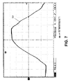
- FIG. 3 shows a power grid synchronized half wave signal measured from a power grid synchronization monitoring circuit at the input pin 1 of an MCU shown in FIG. 2 , according to one embodiment of the present invention
- FIG. 4 illustrates the length of a first life testing detection period P 1 , a second life testing detection period P 2 , and their relation to the synchronized half wave signal as shown in FIG. 3 , according to one embodiment of the present invention
- FIG. 5 shows a signal received at the gate of a switching device of a ground fault simulation unit shown in FIG. 2 , according to one embodiment of the present invention
- FIG. 6 shows a signal received at the gate of a switching device of a trip coil circuit shown in FIG. 2 , according to one embodiment of the present invention
- FIG. 7 shows a voltage waveform received at the anode of the switching device of the trip coil circuit shown in FIG. 2 , according to one embodiment of the present invention
- FIG. 8 shows a voltage waveform received at the anode of a diode of the trip coil circuit shown in FIG. 2 , according to one embodiment of the present invention.
- FIG. 9 shows an output voltage waveform of a leakage current detection circuit shown in FIG. 2 , according to one embodiment of the present invention.
- “around”, “about” or “approximately” shall generally mean within 20 percent, preferably within 10 percent, and more preferably within 5 percent of a given value or range. Numerical quantities given herein are approximate, meaning that the term “around”, “about” or “approximately” can be inferred if not expressly stated.
- unit and “circuit” are interchangeable, and refer to a configuration of electrically or electromagnetically electrically coupled components or devices.
- switch refers to a device for changing the course (or flow) of a circuit, i.e., a device for making or breaking an electric circuit, or for selecting between multiple circuits.
- a switch or switching device has two states: a conductive state and a non-conductive state. When the switching device is in the conductive state, a current is allowed to pass through. When the switching device is in the non-conductive state, no current is allowed to pass through.
- AC refers to alternate current
- DC refers to direct current
- AFCI refers to arc fault circuit interrupter
- GFCI ground fault circuit interrupter
- LED refers to light emitting diode
- MCU microcontroller unit
- SCR silicon controlled rectifier
- the present invention discloses an apparatus and method for testing the life of a leakage current protection device.
- the leakage current protection device has a leakage current detection circuit and a trip mechanism having a switch device.
- the switch device has a gate, an anode and a cathode.
- the leakage current detection circuit of the leakage current protection device has two inductive coils adapted for detecting a leakage current.
- the apparatus includes a ground fault simulation unit, a fault detector of the leakage current detection circuit and the trip mechanism, and a life testing detection control unit having a microcontroller unit (MCU) for controlling operation of the fault detector.
- MCU microcontroller unit
- a first signal (pulse signal) is sent to the gate of the switching device to generate a first voltage at the cathode of the switching device
- a second signal is sent to the ground fault simulation unit to generate a simulated ground fault for the leakage current detection circuit to generate a second voltage at the gate of the switching device
- the first and second voltages are measured to determine whether a fault exists in the leakage current detection circuit and the trip mechanism.
- the apparatus of the present invention in operation detects a leakage current in the leakage current protection device, compares the leakage current with a predetermined threshold and consequently outputs a leakage current protection (and/or alarm) signal if a fault occurs and/or the life of leakage current protection device reaches its end. In this sense, the invented apparatus is an intelligently testing apparatus of the life of devices.
- a silicon controlled rectifier constitutes a key component of the trip mechanism of the leakage current protection device.
- SCR silicon controlled rectifier
- the trip mechanism depends not only on whether the trip coil conducts current, but also on the other conditions such as the current level and the duration of current conduction.
- the current level must be strong enough and the duration of current conduction must be long enough.
- the descending edge of the positive cycle of the AC power is selected to turn on the SCR when the instant value exceeds a pre-determined value.
- the leakage current detection circuit is tested to determine whether the current passes through the SCR. Immediately after the SCR is turned on, the AC power crosses zero volt level and enters the negative cycle, the SCR is turned off. Since the SCR is turned on only for a very brief moment, the current passing through the SCR is small enough to ensure the trip mechanism is not tripped.
- the trip mechanism also includes a trip coil and a trip switch.
- the trip switch has to two pairs of terminals. One pair is corresponding to a pair of LINE terminals for connecting to an AC power source and the other pair is corresponding to a pair of LOAD terminals for connecting to one or more electrical appliances.
- the trip switch When the trip switch is in the conductive state, the first LINE terminal is electrically coupled to the first LOAD terminal and the second LINE terminal is electrically coupled to the second LOAD terminal, respectively.
- the trip switch is in the non-conductive state, the first and second LINE terminals are electrically decoupled from the first and second LOAD terminal, respectively.
- the trip switch is operated by the trip coil. When the trip coil is set in its conductive state, a current is allowed to pass through. When the trip switch is set in its non-conductive state, the AC power at the pair of LINE terminals is disconnected from the pair of LOAD terminals.
- the apparatus detects faults within the leakage current detection circuit for the leakage current protection device and the trip mechanism in the real time for testing the life of the leakage current protection device.
- the apparatus sets the switching device SCR in its conductive state in a substantially short period of time, and tests whether the leakage current detection circuit for the leakage current protection device and the trip mechanism work properly.
- the SCR Shortly after the SCR is set in the conductive state, the voltage of the AC power crosses the zero line and thus sets the switching device SCR into its non-conductive state.
- the duration of the switching device SCR in the conductive state is so short such that the current passing through is not strong enough to activate the trip mechanism. If they are not working properly, at least one of an audio alarm circuit and a visual alarm circuit is activated.
- the present invention can be found many applications in different types of leakage current protection devices including GFCI and AFCI.
- the apparatus 300 includes a leakage current protection circuit 100 , an intelligent life testing and alarm circuit 200 based on an MCU 209 , and a ground fault simulation unit 250 for generating a simulated leakage current.
- the leakage current protection circuit 100 has a first input 151 , a second input 153 , a third input 155 , a fourth input 157 , a first output 172 , a second output 174 , a third output 176 , a reset circuit 103 having an input 103 a that is electrically coupled to the third input 155 , and an output 103 b that is electrically coupled to the first output 172 , a trip coil circuit 104 having a switching device SCR 101 that has a gate, an anode and a cathode, a first input 104 a 1 that is electrically coupled to the output 103 b of the reset circuit 103 and the first output 172 , a second input 104 a 2 that is electrically coupled to the fourth input 157 , an output 104 b that is electrically coupled to the second output 174 , and a leakage current detection circuit 107 having an output 107 b that is electrically coupled to the third output 176 of the leakage current protection circuit
- the first input 151 and the second input 153 of the leakage current protection circuit 100 are operatively coupled to a line phase terminal and a line neutral terminal of an AC power supply.
- the leakage current protection circuit 100 also includes a trip switch SW 101 having two LINE terminals 151 a and 153 a that are electrically coupled to the first input 151 and the second input 153 , respectively, and two LOAD terminals 151 b and 153 b that are electrically coupled to the inputs of an electrical appliance, respectively, as shown in FIG. 2 .
- the intelligent life testing and alarm circuit 200 has an MCU 209 , a power grid signal synchronization monitoring circuit 204 , a power supply circuit 201 and an alarm circuit 208 .
- the MCU 209 includes a first input A 1 that is electrically coupled to the second output 174 of the leakage current protection device 100 , a second input A 2 , a third input A 3 that is electrically coupled to the output 107 b of the leakage current detection device 107 and the third output 176 of the leakage current protection device 100 , a first output B 1 that is electrically coupled to the third input 155 of the leakage current protection device 100 , a second output B 2 , a third output B 3 , a fourth output B 4 that is electrically coupled to the second input 104 a 2 of the trip coil circuit 104 and the fourth input 157 of the leakage current protection device 100 , and a power supply input P.
- the power grid signal synchronization monitoring circuit 204 has an input 204 a that is electrically coupled to the first output 172 of the leakage current protection device 100 , and an output 204 b that is electrically coupled to the second input A 2 of the MCU 209 .
- the alarm circuit 208 has an input 208 a that is electrically coupled to the third output B 3 of the MCU 209 , and a power supply input 208 p .
- the power supply circuit 201 has an input 201 a that is electrically coupled to the first output 172 of the leakage current protection device 100 , and an output 201 b that is electrically coupled to the power supply input P of the MCU 209 and the power supply input 208 p of the alarm circuit 208 .
- the ground fault simulation unit 250 includes an input 250 a that is electrically coupled to the second output B 2 of the MCU 209 , a first output 250 b 1 that is electrically coupled to the first input 151 of the leakage current protection device 100 and a second output 250 b 2 that is electrically coupled to the second input 153 of the leakage current protection device 100 .
- the power grid signal synchronization monitoring circuit 204 generates a first signal that is synchronized with an AC power from the first input 151 and the second input 153 of the leakage current protection device 100 to form a power grid signal synchronization signal, the power grid signal synchronization signal is electrically coupled to the second input A 2 of the MCU 209 ; the MCU 209 generates when the power grid signal synchronization signal reduces to a first predetermined threshold value during every positive half-wave of the AC power, and a second signal from the second output B 2 to the ground fault simulation unit 250 to generate a simulated ground fault signal; the leakage current detection circuit 107 generates a third signal in responsive to the simulated ground fault signal and the pulse signal, which is input into the third input A 3 of the MCU 209 ; the gate of the switching device SCR 101 receives the pulse signal to turn the switching device SCR 101 into its conductive state during the pulse period; the MCU 209 receives a DC voltage at the first input A 1 of the MCU 209 , and
- the MCU 209 is programmable. In one embodiment, the MCU 209 is programmed such that if the DC voltage is greater than the predetermined threshold value, no fault exists in the leakage current protection device 100 , and if the DC voltage is less than the predetermined threshold value, at least one fault exists in the leakage current protection device 100 .
- the apparatus 300 provides a surge protection function.
- the MCU 209 sends a signal to a switching device SCR 101 to set the trip switch SW 101 in its non-conductive state and to disconnect the AC power from the LINE terminals 151 a and 153 a to the LOAD terminals 151 b and 153 b of the trip switch SW 101 .
- the switching device SCR 101 comprises a silicon controlled rectifier.
- the switching device SCR 101 When the switching device SCR 101 is in its conductive state, the switching device SCR 101 passes current in the positive half-wave of the AC power to set the trip switch SW 101 in its non-conductive state and to disconnect the AC power from the LINE terminals to the LOAD terminals of the trip switch SW 101 .
- the apparatus 300 continues to detect faults of the leakage current protection device 100 .
- the MCU 209 sends a signal to a reset switching device SCR 102 to set the trip switch SW 101 in the conductive state and to connect the AC power from the LINE terminals to the LOAD terminals of the trip switch SW 101 .
- the length of the predetermined timeout period is adjustable. Accordingly, the apparatus 200 also provides an automatic reset function.
- the MCU 209 determines that at least one fault exists, the MCU 209 sends an alarm signal to the alarm circuit 208 , and the alarm circuit 208 receives the alarm signal and generates an alarm.
- the alarm circuit 208 comprises at least one of an audio alarm circuit 202 for generating an audible alarm and a visual alarm circuit 203 for generating a visible alarm.
- FIG. 2 shows a circuit diagram of an apparatus for intelligently testing the life of a leakage current protection device according to one embodiment of the present invention.
- the apparatus 300 includes a ground fault simulation unit 250 for generating a simulated leakage current, a leakage current protection circuit 100 , and an intelligent life testing and alarm circuit 200 based on an MCU 209 .
- the ground fault simulation unit 250 has a switching device SCR 301 having a gate, an anode and a cathode, and a resistor R 301 .
- the resistor R 301 is electrically connected between the hot wire (through the line phase terminal 151 ) of the AC power supply and the anode of the switching device SCR 301 .
- the cathode of the switching device SCR 301 is connected to the line neutral terminal 153 a of the trip switch SW 101 which is electrically connected to the neutral wire 153 of the AC power supply after passing through two inductive coils L 1 and L 2 .
- the gate of the switching device SCR 301 is electrically connected to an output pin 7 (B 2 ) of the MCU 209 .
- the switching device SCR 301 When a signal output from the output pin 7 (B 2 ) of the MCU 209 is received by the gate of the switching device SCR 301 , it can set the switching device SCR 301 in either its conductive or its non-conductive state, depending on the output signal of the MCU 209 .
- the voltage at the output pin 7 (B 2 ) of the MCU 209 reaches a predetermined voltage level, the voltage at the gate of the switching device SCR 301 sets the switching device SCR 301 in the conductive state, thereby causing an imbalance between the currents passing through the line phase terminal 151 (hot wire) and the line neutral terminal 153 , which can be detected by the leakage current detection circuit 107 electrically coupled with the inductive coils L 1 and L 2 .
- the leakage current protection device 100 comprises two inductive coils L 1 and L 2 adapted for detecting a leakage current, a leakage current detection circuit 107 , a half-wave rectification circuit 101 , a manual testing circuit 102 , a reset circuit 103 , a trip coil circuit 104 and a trip switch SW 101 .
- the trip switch SW 101 has a pair of LINE terminals (a line phase terminal 151 a and a line neutral terminal 153 a ) in one side and a pair of LOAD terminals 151 b and 153 b in another side, where the line phase terminal 151 a and the line neutral terminal 153 a pass through both inductive coils L 1 and L 2 and are connected to a line phase terminal 151 and a line neutral terminal 153 , respectively, of an AC power supplier, and a pair of LOAD terminals 151 b and 153 b are connected to one or more loads.
- the trip switch SW 101 When the trip switch SW 101 is in its conductive state, the AC power is supplied from the LINE terminals to the LOAD terminals.
- the trip switch SW 101 When the trip switch SW 101 is in its non-conductive state, no AC power is supplied from the pair of LINE terminals to the pair of LOAD terminals.
- Each of inductive coils L 1 and L 2 electrically coupled to the leakage current detection circuit
- the half-wave rectification circuit 101 includes a rectifier diode D 101 having a cathode and an anode connected to the line phase terminal 151 , and a current limiting resistor R 101 having two terminals with one connected to the cathode of the rectifier diode D 101 and the other connected to an input 107 a of the leakage current detection circuit 107 .
- the line phase terminal 151 is corresponding to the first input of the leakage current protection device 100
- the line neutral terminal 153 is corresponding to the second input of the leakage current protection device 100 , as shown in FIG. 1 .
- the half-wave rectification circuit 101 provides a DC power to the leakage current detection circuit 107 .
- the manual testing circuit 102 has a push-on release-off switch SW 102 having two terminals and a resistor R 102 having two terminals with one electrically coupled to the line phase terminal 151 and the other connected to one terminal of the push-on release-off switch SW 102 , whose other terminal is connected to a LOAD terminal 151 b of the trip switch SW 101 .
- the LOAD terminal 151 b of the trip switch SW 101 is connected to the line phase terminal 151 a of the trip switch SW 101 when the trip switch SW 101 is in its conductive state.
- the push-on release-off switch SW 102 and the resistor R 102 are connected in series.
- the manual testing circuit 102 is adapted for manually testing the leakage current protection device.
- the reset circuit 103 comprises a switching device SCR 102 having a gate, an anode and a cathode, a capacitor C 101 having two terminals and a reset coil S 2 having two terminals.
- the switching device SCR 102 and the reset coil S 2 are connected in series, and the switching device SCR 102 and the capacitor C 101 are connected in parallel.
- the reset coil S 2 has one terminal electrically coupled to the line phase terminal 151 and the other terminal connected to the anode of the switching device SCR 102
- the capacitor C 101 has its one terminal connected to the gate of the switching device SCR 102 and the other terminal connected to the cathode of the switching device SCR 102 , which is grounded.
- the gate of the switching device SCR 102 is in turn connected to a pin 2 (B 1 ) of the MCU 209 .
- An input signal to the gate of the switching device SCR 102 can make the switching device SCR 102 either in its conductive or its non-conductive state.
- the reset coil S 2 is electrically coupled to an AC power supply (through the line phase terminal 151 ) and the reset coil S 2 maintains the trip switch SW 101 in the conductive state such that the AC power is connected from the LINE terminals 151 a and 153 a to the LOAD terminals 151 b and 153 b of the trip switch SW 101 .
- the trip coil circuit 104 comprises a switching device SCR 101 having a gate, an anode and a cathode, a capacitor C 102 having two terminals, a diode D 102 having an anode and a cathode and a trip coil S 1 having two terminals, as shown in FIG. 2 .
- the trip coil S 1 has its one terminal electrically coupled to the line phase terminal 151 and the other terminal connected to the anode of the switching device SCR 101 .
- the capacitor C 102 has its one terminal connected to the gate of the switching device SCR 101 and the other terminal connected to the cathode of diode D 102 , respectively.
- the cathode of the switching device SCR 101 is electrically connected to the anode of the diode D 102 , whose cathode is grounded. Furthermore, the gate of the switching device SCR 101 is connected to a pin 4 (B 4 ) of the MCU 209 . The cathode of the switching device SCR 101 (the anode of the diode D 102 ) is also connected to a pin 3 (A 1 ) of the MCU 209 .
- the trip coil S 1 when the switching device SCR 101 is in its conductive state, the trip coil S 1 is connected to an AC power supply (through the line phase terminal 151 ) and the trip coil S 1 sets the trip switch SW 101 into its non-conductive state (a trip state).
- the trip switch SW 101 maintains its state until a current passes through either the trip coil S 1 or the reset coil S 2 .
- the trip switch SW 101 responds to the action of the trip coil S 1 and the reset coil S 2 .
- the leakage current detection circuit 107 detects a leakage current, the leakage current detection circuit 107 generates a signal that is sent to the pin 5 (A 3 ) of the MCU 209 .
- the MCU 209 responsively send a signal from the pin 4 (B 4 ) to the gate of the switch device SCR 101 to set the switch device SCR 101 in its conductive state. Accordingly, the power supply energizes the trip coil S 1 to set the trip switch SW 101 in its non-conductive state so that the AC power is disconnected from the LINE terminals 151 a and 153 a to the LOAD terminals 151 b and 153 b of trip switch SW 101 , i.e. in the trip state.
- the reset circuit 103 energizes the reset coil S 2 through the switching device SCR 102 to reset the trip switch SW 101 back to the conductive state so that the AC power is connected from the LINE terminal 151 a and 153 a to the LOAD terminals 151 b and 153 b of the trip switch SW 101 .
- the intelligent life testing and alarm circuit 200 has the MCU 209 , a power supply 201 electrically coupled to the MCU 209 , a power grid signal synchronization monitoring circuit 204 , and an alarm unit 202 and/or 203 .
- the MCU 209 includes a general purpose integrated circuit with a timer function, or an application specific integrated circuit such as a 555 timer chip.
- the power supply circuit 201 comprises a rectifying diode D 201 , a resistor R 201 , a regulator diode Z 201 , a first voltage stabilizing capacitor C 201 , a second voltage stabilizing capacitor C 202 , and a light emitting diode LED 201 .
- the anode of the diode D 201 is electrically connected to the hot wire of the AC power through the line phase terminal 151 .
- the cathode terminal of the diode D 201 is electrically connected to a first end of the resistor R 201 .
- a second end of the resistor R 201 is electrically connected to a terminal Vcc and provides a DC power supply voltage to the terminal Vcc.
- the regulator diode Z 201 has its cathode and anode electrically connected to the terminal Vcc and the ground, respectively.
- the first voltage stabilizing capacitors C 201 has its two terminals electrically connected to the electrically connected to the terminal Vcc and the ground, respectively, as well.
- the regulator diode Z 201 and first voltage stabilizing capacitors C 201 coupled to each other in parallel to form a voltage regulator to further regulate the voltage of the terminal Vcc.
- the light emitting diode LED 201 has its anode electrically connected to the terminal Vcc and its cathode electrically connected to one terminal of the second voltage stabilizing capacitor C 202 , which is electrically connected to a pin 10 (P) of the MCU 209 for supplying the power from the power supply circuit 201 to the MCU 209 .
- the other terminal of the second voltage stabilizing capacitor C 202 is electrically connected to the anode of the regulator diode Z 20 , which is electrically connected to the ground.
- the regulator diode Z 201 and the voltage stabilizing capacitor C 202 are adapted for regulating the power supply to an appropriate voltage for the MCU 209 .
- the LED 201 may also be used as an indication of working conditions of the leakage current protection device unit 100 .
- the power grid signal synchronization monitoring circuit 204 includes a voltage divider having a first resistor R 206 and a second resistor R 207 .
- the input to the circuit 294 is a DC power supplied from the cathode of the diode D 201 .
- the first resistor R 206 and the second resistor R 207 forming the voltage divider are adapted for reducing the DC voltage to an appropriate value of voltages, inputting to the input pin 1 (A 2 ) of the MCU 209 .
- the output signal to the MCU 209 is a synchronized half-wave waveform used as a sampling of the power grid alternate current waveform.
- the alarm unit includes at least of an audio alarm circuit 202 and a visual alarm circuit 203 . As shown in FIG. 2 , the alarm unit comprises both the audio alarm circuit 202 and the visual alarm circuit 203 .
- the audio alarm circuit 202 has a speaker, a switching device SCR 201 , and a voltage dividing resistor R 202 .
- a transistor or an SCR may be used as the switching device, depending upon applications.
- a DC voltage output from the half-wave rectifier D 201 is applied to the speaker through the voltage dividing resistor R 202 and the switching device SCR 201 .
- the switching device SCR 201 is in a non-conductive state and the speaker remains silent.
- an output from the pin 9 (B 2 ) of the MCU 209 electrically connected to the gate of the switching device SCR 201 turns the switching device SCR 201 to its conductive state, the speaker produces an audible alarm.
- An optional integrated circuit may be used to generate special alarm sounds.
- the visual alarm circuit 203 has a resistor R 203 , a light emitting diode LED 202 , a switch SW 201 and a resistor R 204 .
- the switch SW 201 has its one terminal electrically connected to the cathode of the diode D 201 of the power supply circuit 201 and the other terminal electrically connected to one terminal of the resistor R 204 whose other terminal is electrically connected to the pin 8 (B 3 ) of the MCU 209 .
- the resistor R 203 is electrically connected between the other terminal of the resistor R 204 and the anode of the light emitting diode LED 202 whose cathode is grounded.
- the output at the pin 8 (B 3 ) of the MCU 209 is in a low voltage state and the LED 202 is not lit.
- the MCU 209 detects the malfunction of the leakage current detection circuit 107 or the trip coil S 1 , the output at the pin 8 of the MCU 209 is in a high voltage state, which causes the light emitting diode LED 202 to generate a visible alarm.
- the switch SW 201 is a mechanical contact switch associated with trip protections. When the leakage current protection device 100 trips, the switch SW 201 is set in its conductive state, causing the lighting of the LED 202 . The lighting of the LED 202 indicates either the leakage current protection device unit 100 is in a trip condition or the leakage current detection circuit 100 is not working properly.
- FIGS. 3 and 4 the length and relative phase of a first life testing detection period P 1 , a second life testing detection period P 2 , and their relation to a power grid signal are illustrated according to one embodiment of the present invention.
- a completed output waveform 301 of the voltage of the power grid signal synchronization monitoring circuit 204 is illustrated in FIG. 3 . Since the input to the power grid signal synchronization monitoring circuit 204 is the output of the rectifying diode D 102 , only the positive half cycle is shown. This complete cycle is divided into two independent time periods: a first life testing detection period P 1 and a second life testing detection period P 2 , as shown in FIG. 4 .
- the first life testing detection period P 1 starts at t 1 after the power grid reaches its peak.
- the voltage of the AC power After the AC power reaches its peak, the voltage of the AC power starts to decrease.
- the voltage of the synchronized power grid signal starts to decrease since it is proportional to the AC power during its positive half cycle.
- the input pin 1 of the MCU receives this voltage and compares to a predetermined voltage value V 1 .
- the MCU suspends its leakage current detection and starts life testing detection and the first life testing detection period P 1 .
- the AC power voltage continues to decrease until it reaches another level that is less than another predetermined voltage value V 2 , at time t 2 .
- the MCU resumes its leakage current detection, stops the first life testing detection period P 1 and starts the second life testing detection period P 2 .
- At least one of the starting time t 1 of P 1 and t 2 of P 2 is adjustable. The adjustment is made by adjusting at least one of the predetermined voltage values V 1 and V 2 .
- at least one of the length of the first life testing detection period P 1 and the length of the second life testing detection period P 2 is adjustable in a similar manner. This cycle repeats for every complete cycle of the AC power.
- the ground fault simulation unit 250 comprises a switching device SCR 301 have a gate, an anode and a cathode, and a resistor R 301 having a first terminal and a second terminal.
- the first terminal of the first resistor R 301 is electrically coupled to the hot wire (through the line phase terminal 151 ) of the AC power supply.
- the second terminal of the first resistor R 301 is connected to the anode of the switching device SCR 301 .
- the cathode of the switching device SCR 301 is connected to the line neutral terminal 153 a of the trip switch SW 010 which is electrically connected to the neutral wire 153 of the AC power supply after passing through two inductive coils L 1 and L 2 .
- the gate of the switching device SCR 301 is electrically connected to an output pin 7 (B 2 ) of the MCU 209 .
- the output signal from pin 7 (B 2 ) of the MCU 209 is sent to the gate of the switching device SCR 301 to set the switching device SCR 301 in either its conductive or its non-conductive state, depending on the output signal of the MCU 209 .
- the voltage at the output pin 7 (B 2 ) of the MCU 209 reaches a predetermined voltage level, the voltage at the gate of the switching device SCR 301 sets the switching device SCR 301 in the conductive state. Because of the configuration shown in FIG.
- the switching device SCR 301 passes a current only when the AC power enters positive half-wave so that a simulated ground fault is generated between the hot wire and neutral wire of the AC power supply.
- the switching device SCR 301 is automatically set into the non-conductive state where no current is allowed to pass through.
- the life testing detection control unit includes an MCU 209 , and an alarm unit having an audio alarm circuit 202 and a visual alarm unit 203 .
- the MCU 209 can be an independent unit or a shared unit with the life testing detection control unit, the fault detector for the leakage current detection circuit and the trip mechanism. If a fault exists in the leakage current detection circuit and the trip mechanism of the leakage current protection device, the MCU 209 activates the alarm unit. When a fault occurs, the audio alarm circuit 202 generates an audible alarm, and the LED LED 202 of the visual alarm circuit 203 generates a visible alarm to alert user of the leakage current protection device.
- An application specific integrated circuit (ASIC) may be used to generate specific alarm sounds with the speaker.
- a regular speaker or a piezo buzzer may be used as the speaker in the circuit.
- a fault detector for a leakage current detection circuit and trip mechanism includes the MCU 209 , the power supply 201 electrically coupled to the MCU 209 , the ground fault simulation unit 250 , the trip coil circuit 104 , and the alarm unit.
- the MCU 209 can be an independent unit or a shared unit with the life testing detection control unit according to embodiments of the present invention.
- the MCU 209 is a main control unit for the intelligent life testing detection device of the leakage current protection device.
- the MCU 209 includes a general purpose integrated circuit with a timer function, or an application specific integrated circuit such as a 555 timer chip.
- the power grid signal synchronization monitoring circuit 204 provides a power grid synchronization signal.
- the input to the power grid signal synchronization monitoring circuit 204 is electrically coupled to the power grid through the cathode of the diode D 201 of the power supply 201 .
- the output signal 301 of the power grid signal synchronization monitoring circuit 204 shows only the positive half of the power grid waveform.
- the positive half of the power grid waveform passes through a voltage divider having a first resistor R 206 , and a second resistor R 207 , so that the output voltage of the power grid synchronization monitoring circuit 204 reaches an appropriate level.
- the values of the resistance of the first resistor R 206 and the second resistor R 207 are chosen so that the ratio of voltages across the first resistor R 205 and across the second resistor R 207 is in a range of about 50-200.
- the power grid synchronized signal is sent to the input pin 1 (A 2 ) of the MCU 209 .
- a first predetermined voltage value for example, V 1
- the first life testing detection period P 1 starts.
- the leakage current detection is suspended.
- the MCU 209 sends out a signal from the output pin 7 (B 2 ) to the gate of the switching device SCR 301 of the ground fault simulation unit 250 so as to generate a simulated ground fault signal during the life testing detection window, as shown in FIG. 5 . If there is no fault in the leakage current detection circuit 107 of the leakage current protection device 100 , the output of the leakage current detection circuit 107 generates a detectable pulse signal at the input pin 5 (A 3 ) of the MCU 209 , in response to the simulated ground fault signal. The pulse signal is shown as the first pulse 701 in FIG. 8 .
- the leakage current detection circuit 107 of the leakage current protection device 100 works properly and no fault exists in the leakage current detection circuit of the leakage current protection device. Otherwise, if the pulse signal is not received at the input pin 5 of the MCU during the first life testing detection period P 1 , the leakage current detection circuit of the leakage current protection device does not work properly and at least one fault exists in the leakage current detection circuit of the leakage current protection device.
- the pulse signal is overlaid with a power grid waveform to show the phase relationship between the pulse signal and the power grid waveform.
- This pulse sets the switching device SCR 101 in conductive state.
- the voltage at the anode of the switching device SCR 101 is measured through an A/D converter of the pin 3 of the MCU. If the voltage is at or near a predetermined threshold while the switching device SCR 101 is in conductive state during the pulse period, then the trip coil circuit and trip mechanism is working properly.
- the pulse is very short in time, but it is long enough to set the switching device SCR 101 in its conductive state to allow a current to pass through.
- the voltage across a p-n junction is about 0.7 V for a silicon type SCR.
- the voltage across a p-n junction is about 0.3 V for a Germanium type SCR.
- a second pulse signal is detected by the pin 3 of the MCU as shown as pulse signal 702 in FIG. 8 . This second pulse signal is used to determine whether a fault exists in the trip mechanism. For example, if the trip coil S 1 is broken, the trip coil S 1 is unable to pass current from the AC power from the LINE terminal. Therefore, the peak value of the second pulse signal is very small or equals to zero. If this second pulse signal 702 is not detected at the pin 3 of the MCU, it indicates that at least one fault exists in the trip mechanism.
- FIG. 7 shows the voltage measured at the anode of the switching device SCR 101 according to one embodiment of the present invention.
- FIG. 8 shows the voltage measured at the anode of the diode D 102 according to one embodiment of the present invention.
- An alarm is generated by the MCU and sent to at least one of the audio alarm circuit 202 and the visual alarm circuit 203 of the life testing detection control unit when at least one fault exists in the leakage current detection circuit and the trip mechanism of the leakage current protection device.
- the audio alarm circuit 202 produces an audible alarm and the visual alarm circuit produces a visible alarm.
- the intelligent life testing detection device of the leakage current protection device provides surge protection functionality.
- surge protection functionality When the voltage of an AC power input reaches an unusual level, such voltage surge may cause damage to electrical appliances connected to the LOAD terminal of a leakage current protection device.
- the input voltage of the AC power is monitored by the power grid synchronization monitoring circuit 204 . If the monitored voltage reaches a predetermined threshold, the output pin 4 of the MCU sets the switching device SCR 101 in conductive state so that the trip mechanism is activated and the AC power from the LINE terminal of the leakage current protection device to the LOAD terminal is disconnected. Therefore, the surge protection functionality is provided by the intelligent life testing detection device of the leakage current protection device. An alarm signal is sent to the alarm unit to alert user of the leakage current protection device.
- the intelligent life testing detection device of the leakage current protection device can be automatically reset.
- the MCU attempts to reset the intelligent life testing detection device of the leakage current protection device by sending out pulse through pin 2 to set the switching device SCR 102 of the reset circuit 103 . If the leakage current is not longer present, then the intelligent life testing detection device of the leakage current protection device is successfully reset and the AC power is reconnected from the LINE terminal to the LOAD terminal of the leakage current protection device. Therefore the intelligent life testing detection device of the leakage current protection device provides an automatically reset function.
- Another aspect of the present invention provides a method of intelligently testing the life of a leakage current protection device having a leakage current detection circuit and a trip mechanism.
- the method comprises the steps of:
- the step of alerting user of the leakage current protection device with the alarm unit when at least one fault is detected in the leakage current protection device comprises at least one of the steps of:
- the audio alarm circuit 202 is adapted to produce an audible alarm.
- the visual alarm circuit 203 is adapted to produce a visible alarm.
- the step of detecting fault in leakage current protection device with the fault detector comprising the step of detecting fault in a leakage current detection circuit of the leakage current protection device with a fault detector.
- the fault detector comprises:
- the step of detecting fault in leakage current protection device with the fault detector comprising the steps of:
- the switching device SCR 101 is able to establish the voltage at the cathode of the switching device SCR 101 when no fault exists in the trip mechanism of the leakage current detection device, during the positive half-wave of the AC power.
- the switching device SCR 101 is able to establish the voltage at the gate of the switching device SCR 101 when no fault exists in the leakage current detection circuit of the leakage current detection device, during the negative half-wave of the AC power. If the received voltage at the cathode of the switching device SCR 101 is less than a predetermined threshold value, during the positive half-wave of the AC power, it is determined that at least one fault exists in the trip mechanism of the leakage current detection device. If the received voltage at the gate of the switching device SCR 101 is less than a predetermined threshold value, during the negative half-wave of the AC power, it is determined that at least one fault exists in the leakage current detection circuit of the leakage current detection device.
- the method for intelligently testing the life of a leakage current protection device includes the step of providing a testing device, having a microcontroller unit (MCU); a power grid signal synchronization monitoring circuit; an alarm circuit; a power supply circuit; and a ground fault simulation unit, as described above.
- MCU microcontroller unit
- the method further includes the steps of generating a power grid synchronization signal that is received at the second input of the MCU, by the power grid signal synchronization monitoring circuit; producing a pulse signal when the power grid signal synchronization signal reduces to a first predetermined threshold value and a second signal during every positive half-wave of the AC power by the MCU, wherein the pulse signal is output to the gate of the switching device, and the second signal is output to the ground fault simulation unit so as to generate a simulated ground fault signal therein; and generating a third signal in responsive to the simulated ground fault signal, which is received at the third input of the MCU.
- the method includes the steps of received the pulse signal at the gate of the switching device to turn the switching device into a conductive state during the pulse period; detecting a DC voltage between the gate and the cathode of the switching device; and comparing the DC voltage to a second predetermined threshold value by the MCU to determine whether a fault exists in the leakage current protection device, wherein the MCU is programmed such that if the DC voltage is greater than the second predetermined threshold value, no fault exists in the leakage current protection device, and if the DC voltage is less than the second predetermined threshold value, a fault exists in the leakage current protection device.
- the method includes the steps of and activating the alarm circuit by the MCU if a fault exists in the leakage current protection device to generate an alarm to alert users of the leakage current protection device.
- the activating the alarm circuit step further comprising at least of one of following steps activating an audio alarm circuit for generating an audible alarm; and activating a visual alarm circuit for generating a visible alarm.
Abstract
Description
-
- detecting fault in leakage current protection device with a fault detector; and
- alerting user of the leakage current protection device with a life testing detection unit having an MCU and an alarm unit when at least one fault is detected in the leakage current protection device.
-
- alerting user of the leakage current protection device that at least one fault exists in the leakage current protection device with an
audio alarm circuit 202; and - alerting user of the leakage current protection device that at least one fault exists in the leakage current protection device with a
visual alarm circuit 203.
- alerting user of the leakage current protection device that at least one fault exists in the leakage current protection device with an
-
- a ground
fault simulation unit 250; - a
trip coil circuit 104 having a switching device SCR101, a trip coil S1, and a trip switching SW101 having a LINE terminal for connecting to an AC power and a LOAD terminal; - a power grid signal
synchronization monitoring circuit 204; and - a
reset circuit 103 having a reset coil S2, a reset switching device SCR102 and the trip switching SW101.
- a ground
-
- sending a pulse signal to the gate of the switching device SCR101 at a predetermined phase of the AC power during positive half-wave of the AC power to generate a voltage at the cathode of the switching device SCR101;
- sending a signal to the ground
fault simulation unit 250 to generate a simulated ground fault for leakage current detection circuit during negative half of the AC power to generate a voltage at the gate of the switching device SCR101; - receiving the voltage at the cathode of the switching device SCR101 during the positive half-wave of the AC power,
- receiving the voltage at the gate of the switching device SCR101 during the negative half-wave of the AC power; and
- analyzing the received voltages to determine whether at least one fault exists in the leakage current detection circuit and the trip mechanism.
Claims (20)
Applications Claiming Priority (2)
| Application Number | Priority Date | Filing Date | Title |
|---|---|---|---|
| CNB2005101328423A CN1319101C (en) | 2005-12-27 | 2005-12-27 | Lift stop intelligent detection and detector for leakage protector |
| CN200510132842.3 | 2005-12-27 |
Publications (2)
| Publication Number | Publication Date |
|---|---|
| US20070146947A1 US20070146947A1 (en) | 2007-06-28 |
| US7492559B2 true US7492559B2 (en) | 2009-02-17 |
Family
ID=36919031
Family Applications (1)
| Application Number | Title | Priority Date | Filing Date |
|---|---|---|---|
| US11/588,163 Active 2027-09-06 US7492559B2 (en) | 2005-12-27 | 2006-10-26 | Intelligent life testing methods and apparatus for leakage current protection |
Country Status (2)
| Country | Link |
|---|---|
| US (1) | US7492559B2 (en) |
| CN (1) | CN1319101C (en) |
Cited By (8)
| Publication number | Priority date | Publication date | Assignee | Title |
|---|---|---|---|---|
| US20070195470A1 (en) * | 2006-02-21 | 2007-08-23 | General Protecht Group, Inc. | Intelligent life testing methods and apparatus for leakage current protection |
| US20100053826A1 (en) * | 2000-11-21 | 2010-03-04 | Pass & Seymour, Inc. | Electrical Wiring Device |
| US20110032236A1 (en) * | 2009-08-06 | 2011-02-10 | Yokogawa Electric Corporation | Measurement apparatus |
| US20110149453A1 (en) * | 2008-07-07 | 2011-06-23 | Leviton Manufacturing Company, Inc. | Fault circuit interrupter device |
| US8514529B1 (en) | 2000-11-21 | 2013-08-20 | Pass & Seymour, Inc. | Electrical wiring device |
| US8861146B2 (en) | 2010-12-17 | 2014-10-14 | Pass & Seymour, Inc. | Electrical wiring device with protective features |
| US9819177B2 (en) | 2013-03-15 | 2017-11-14 | Pass & Seymour, Inc. | Protective device with non-volatile memory miswire circuit |
| US10020649B2 (en) | 2015-07-23 | 2018-07-10 | Pass & Seymour, Inc. | Protective device with self-test |
Families Citing this family (15)
| Publication number | Priority date | Publication date | Assignee | Title |
|---|---|---|---|---|
| CN100477056C (en) | 2006-04-03 | 2009-04-08 | 温州三蒙科技电气有限公司 | Multiple protective circuit breaker device with indicating lamp and automatic monitor |
| US7808245B2 (en) * | 2007-09-28 | 2010-10-05 | Caterpillar Inc | Testing method for a ground fault detector |
| US8335062B2 (en) * | 2010-03-08 | 2012-12-18 | Pass & Seymour, Inc. | Protective device for an electrical supply facility |
| US9948087B2 (en) | 2010-03-08 | 2018-04-17 | Pass & Seymour, Inc. | Protective device for an electrical supply facility |
| US8405939B2 (en) * | 2010-03-08 | 2013-03-26 | Pass & Seymour, Inc. | Protective device for an electrical supply facility |
| US8289664B2 (en) * | 2010-03-08 | 2012-10-16 | Pass & Seymour, Inc. | Protective device for an electrical supply facility |
| US20110313583A1 (en) * | 2010-06-22 | 2011-12-22 | Unified Packet Systems Corp. | Integrated Wireless Power Control Device |
| ES2566981B1 (en) * | 2014-02-05 | 2017-01-13 | Cirprotec, S.L. | COMBINED ELECTRICAL PROTECTION DEVICE AGAINST TRANSITIONAL OVERVOLTAGES AND SUPERVISION OF AN ELECTRICAL INSTALLATION AND OPERATING PROCEDURE OF THE SUCH DEVICE. |
| US9488689B2 (en) * | 2014-08-28 | 2016-11-08 | General Electric Company | Systems and methods for identifying fault location using distributed communication |
| US10243350B2 (en) * | 2015-06-11 | 2019-03-26 | Ze Chen | Protection circuit and ground fault circuit interrupter |
| US10290455B2 (en) * | 2016-01-22 | 2019-05-14 | Carling Technologies, Inc. | Self testing GFCI |
| CN109755921A (en) * | 2017-11-08 | 2019-05-14 | 苏州益而益电器制造有限公司 | Ground-fault interrupter |
| CN107658845B (en) * | 2016-07-26 | 2019-04-02 | 江苏通领科技有限公司 | A kind of GFCI with leakage current test and Self-Test Diagnostics function |
| CN110412398A (en) * | 2019-08-27 | 2019-11-05 | 镇江大全赛雪龙牵引电气有限公司 | A kind of Novel DC traction power supply negative pole unit frame leak-testing and protective device |
| CN111064162A (en) * | 2019-12-31 | 2020-04-24 | 苏州阿德文斯电子科技有限公司 | Leakage circuit design of multifunctional intelligent protector |
Citations (70)
| Publication number | Priority date | Publication date | Assignee | Title |
|---|---|---|---|---|
| US3953766A (en) * | 1974-09-16 | 1976-04-27 | General Electric Company | Ground fault circuit interrupter and electronic module therefor |
| US4931894A (en) | 1989-09-29 | 1990-06-05 | Technology Research Corporation | Ground fault current interrupter circuit with arcing protection |
| US4979070A (en) | 1989-06-13 | 1990-12-18 | Bodkin Lawrence E | Automatic reset circuit for GFCI |
| US5053931A (en) | 1990-08-13 | 1991-10-01 | Rushing John A | Diffuse patio lighting arrangement |
| US5223810A (en) | 1992-08-20 | 1993-06-29 | General Electric Company | Trip-reset mechanism for GFCI receptacle |
| US5229730A (en) | 1991-08-16 | 1993-07-20 | Technology Research Corporation | Resettable circuit interrupter |
| US5334939A (en) | 1992-11-13 | 1994-08-02 | Cooper Industries, Inc. | Ground fault circuit breaker test circuit for panelboards having minimum penetrations and testing circuit breakers without opening panelboard enclosure |
| US5363269A (en) | 1993-02-22 | 1994-11-08 | Hubbell Incorporated | GFCI receptacle |
| US5418678A (en) | 1993-09-02 | 1995-05-23 | Hubbell Incorporated | Manually set ground fault circuit interrupter |
| US5448443A (en) | 1992-07-29 | 1995-09-05 | Suvon Associates | Power conditioning device and method |
| US5477412A (en) | 1993-07-08 | 1995-12-19 | Leviton Manufacturing Co., Inc. | Ground fault circuit interrupter incorporating miswiring prevention circuitry |
| US5541800A (en) | 1995-03-22 | 1996-07-30 | Hubbell Incorporated | Reverse wiring indicator for GFCI receptacles |
| US5642248A (en) | 1995-08-31 | 1997-06-24 | Leviton Manufacturing Co | Electrical extension cord with built-in safety protection |
| US5654857A (en) | 1995-07-19 | 1997-08-05 | Leviton Manufacturing Co., Inc. | Ground fault circuit interrupt system including auxiliary surge suppression ability |
| US5661623A (en) | 1993-09-02 | 1997-08-26 | Hubbell Corporation | Ground fault circuit interrupter plug |
| US5673360A (en) | 1995-09-11 | 1997-09-30 | Scripps; J. Sebastian | Travel Humidifier |
| US5684272A (en) | 1993-02-16 | 1997-11-04 | Leviton Manufacturing Co., Inc. | In-line cord ground fault circuit interrupter |
| US5757598A (en) | 1996-12-27 | 1998-05-26 | Tower Manufacturing Corporation | Ground fault circuit interrupter |
| US5786971A (en) | 1997-07-23 | 1998-07-28 | Leviton Manufacturing Co., Inc. | Ground fault protection circuit for multiple loads with separate GFCI branches and a common neutral for the GFCI electronics |
| US5825599A (en) | 1997-05-05 | 1998-10-20 | Leviton Manufacturing Co., Inc. | Ground fault circuit interrupter system with uncommitted contacts |
| US5899761A (en) | 1997-09-11 | 1999-05-04 | Fiskars Inc. | Power strip |
| US5906517A (en) | 1997-09-11 | 1999-05-25 | Fiskars Inc. | Power strip |
| US5963406A (en) | 1997-12-19 | 1999-10-05 | Leviton Manufacturing Co., Inc. | Arc fault detector with circuit interrupter |
| US6040967A (en) | 1998-08-24 | 2000-03-21 | Leviton Manufacturing Co., Inc. | Reset lockout for circuit interrupting device |
| US6052266A (en) | 1998-10-01 | 2000-04-18 | Tower Manufacturing Corporation | Ground fault circuit interrupter |
| US6052265A (en) | 1998-11-20 | 2000-04-18 | Leviton Manufacturing Co., Inc. | Intelligent ground fault circuit interrupter employing miswiring detection and user testing |
| US6128169A (en) | 1997-12-19 | 2000-10-03 | Leviton Manufacturing Co., Inc. | Arc fault detector with circuit interrupter and early arc fault detection |
| US6246558B1 (en) | 1998-08-24 | 2001-06-12 | Leviton Manufacturing Company | Circuit interrupting device with reverse wiring protection |
| US6252407B1 (en) | 1996-12-18 | 2001-06-26 | Leviton Manufacturing Co., Inc. | Ground fault circuit interrupter miswiring prevention device |
| US6259340B1 (en) | 1999-05-10 | 2001-07-10 | General Electric Company | Circuit breaker with a dual test button mechanism |
| US6262871B1 (en) | 1998-05-28 | 2001-07-17 | X-L Synergy, Llc | Fail safe fault interrupter |
| US6282070B1 (en) | 1998-08-24 | 2001-08-28 | Leviton Manufacturing Co., Inc. | Circuit interrupting system with independent trip and reset lockout |
| US6292337B1 (en) | 1993-08-05 | 2001-09-18 | Technology Research Corporation | Electrical system with arc protection |
| US6381113B1 (en) | 1992-07-22 | 2002-04-30 | Technology Research Corporation | Leakage current protection device adapted to a wide variety of domestic and international applications |
| US6407469B1 (en) | 1999-11-30 | 2002-06-18 | Balboa Instruments, Inc. | Controller system for pool and/or spa |
| US6433555B1 (en) | 1999-02-17 | 2002-08-13 | Eagle Electric Manufacturing Co., Inc. | Electrical circuit interrupter |
| US6437700B1 (en) | 2000-10-16 | 2002-08-20 | Leviton Manufacturing Co., Inc. | Ground fault circuit interrupter |
| US6437955B1 (en) | 1995-09-14 | 2002-08-20 | Tyco Electronics Corporation | Frequency-selective circuit protection arrangements |
| US6442007B1 (en) | 1999-12-28 | 2002-08-27 | Wenzhou Van-Sheen Electric Appliance Co., Ltd. | Ground fault interrupter with display circuit |
| US6465735B2 (en) | 1998-02-24 | 2002-10-15 | Lindy Lawrence May | Modular electrical system |
| US6515564B2 (en) | 1999-02-17 | 2003-02-04 | Eagle Electric Manufacturing Co., Inc. | Electric circuit interrupter |
| US6532139B2 (en) | 2000-05-12 | 2003-03-11 | Human El-Tech, Inc. | Arc fault circuit interrupter and circuit breaker having the same |
| US6538862B1 (en) | 2001-11-26 | 2003-03-25 | General Electric Company | Circuit breaker with a single test button mechanism |
| US6540533B1 (en) | 1997-08-12 | 2003-04-01 | James W. Schreiber | Remote electrical plug ejector |
| US6577478B2 (en) | 2000-08-22 | 2003-06-10 | Human El-Tech, Inc. | Overload circuit interrupter capable of electrical tripping and circuit breaker with the same |
| US6671145B2 (en) | 2001-03-20 | 2003-12-30 | Leviton Manufacturing Co., Inc. | Reset lockout mechanism and independent trip mechanism for center latch circuit interrupting device |
| US6674289B2 (en) * | 2000-02-17 | 2004-01-06 | Pass & Seymour, Inc. | Circuit protection device with half cycle self test |
| US6697238B2 (en) | 2001-02-02 | 2004-02-24 | Hubbell Incorporated | Ground fault circuit interrupter (GFCI) with a secondary test switch contact protection |
| US20040037018A1 (en) * | 2002-08-23 | 2004-02-26 | Byung-Kook Kim | Apparatus and method for determining mis-wiring in a ground fault circuit interrupter |
| US20040070899A1 (en) * | 2002-10-09 | 2004-04-15 | Gershen Bernard J. | Leakage current detection interrupter extension cord with cord diagnostics |
| US6724589B1 (en) | 1999-09-13 | 2004-04-20 | Donald G. Funderburk | Boat electrical test and isolator system |
| US6734769B1 (en) | 2002-12-30 | 2004-05-11 | Leviton Manufacturing Co., Inc. | GFCI receptacle having blocking means |
| US6734680B1 (en) | 2001-04-30 | 2004-05-11 | Albert F. Conard | Ground fault interrupt analyzer method and apparatus |
| US6771152B2 (en) | 2001-03-21 | 2004-08-03 | Leviton Manufacturing Co., Inc. | Pivot point reset lockout mechanism for a ground for fault circuit interrupter |
| US6788504B2 (en) | 2002-06-26 | 2004-09-07 | General Motors Corporation | Mobile electric power supply system with deactivatable GFCI protection |
| US6828886B2 (en) | 1998-08-24 | 2004-12-07 | Leviton Manufacturing Co., Inc. | Reset lockout mechanism and independent trip mechanism for center latch circuit interrupting device |
| US6859044B2 (en) | 2001-06-20 | 2005-02-22 | Arris International, Inc. | Method and architecture for fault protection on a broadband communications network power passing tap |
| US6867954B2 (en) | 2002-08-01 | 2005-03-15 | Zhejiang Dongzheng Electrical Co., Ltd. | Reverse wiring protection device for ground fault circuit interrupter |
| US6897381B2 (en) | 2002-08-30 | 2005-05-24 | The Dial Corporation | Wall-mounted electrical device having adjustable outlet prongs |
| US6915992B1 (en) | 2001-05-17 | 2005-07-12 | Arlington Industries, Inc. | Garden post with improved plastic tube joint |
| US6944001B2 (en) | 1998-08-24 | 2005-09-13 | Leviton Manufacturing Co., Inc. | Circuit interrupting system with independent trip and reset lockout |
| US6946935B2 (en) | 2002-10-09 | 2005-09-20 | Zhejiang Dongzheng Electrical Co., Ltd. | Ground fault circuit interrupter with reverse wiring protection |
| US6949994B2 (en) | 2002-12-30 | 2005-09-27 | Leviton Manufacturing Co., Inc. | GFCI without bridge contacts and having means for automatically blocking a face opening of a protected receptacle when tripped |
| US6954125B2 (en) | 2002-10-09 | 2005-10-11 | Zhejiang Dongzheng Electrical Co., Ltd. | Ground fault circuit interrupter with reverse wiring protection |
| US6958463B1 (en) | 2004-04-23 | 2005-10-25 | Thermosoft International Corporation | Heater with simultaneous hot spot and mechanical intrusion protection |
| US6963260B2 (en) | 2003-02-03 | 2005-11-08 | Leviton Manufacturing Co., Inc. | GFCI receptacle having blocking means |
| US6972572B2 (en) | 2003-12-22 | 2005-12-06 | Leviton Manufacturing Co., Inc. | Arc fault detector |
| US6982856B2 (en) | 2001-03-21 | 2006-01-03 | Leviton Manufacturing Co., Inc. | GFCI with reset lockout |
| US6991495B1 (en) | 2002-10-28 | 2006-01-31 | Tower Manufacturing Corporation | Power strip with self-contained ground fault circuit interrupter module |
| US20060198066A1 (en) | 2005-03-02 | 2006-09-07 | Zhejiang Dongzheng Electrical Co., Ltd | Permanent-magnet ground fault circuit interrupter plug and its permanent-magnet mechanism therein |
-
2005
- 2005-12-27 CN CNB2005101328423A patent/CN1319101C/en active Active
-
2006
- 2006-10-26 US US11/588,163 patent/US7492559B2/en active Active
Patent Citations (91)
| Publication number | Priority date | Publication date | Assignee | Title |
|---|---|---|---|---|
| US3953766A (en) * | 1974-09-16 | 1976-04-27 | General Electric Company | Ground fault circuit interrupter and electronic module therefor |
| US4979070A (en) | 1989-06-13 | 1990-12-18 | Bodkin Lawrence E | Automatic reset circuit for GFCI |
| US4931894A (en) | 1989-09-29 | 1990-06-05 | Technology Research Corporation | Ground fault current interrupter circuit with arcing protection |
| US5053931A (en) | 1990-08-13 | 1991-10-01 | Rushing John A | Diffuse patio lighting arrangement |
| US5229730A (en) | 1991-08-16 | 1993-07-20 | Technology Research Corporation | Resettable circuit interrupter |
| US6381113B1 (en) | 1992-07-22 | 2002-04-30 | Technology Research Corporation | Leakage current protection device adapted to a wide variety of domestic and international applications |
| US5448443A (en) | 1992-07-29 | 1995-09-05 | Suvon Associates | Power conditioning device and method |
| US5223810A (en) | 1992-08-20 | 1993-06-29 | General Electric Company | Trip-reset mechanism for GFCI receptacle |
| US5334939A (en) | 1992-11-13 | 1994-08-02 | Cooper Industries, Inc. | Ground fault circuit breaker test circuit for panelboards having minimum penetrations and testing circuit breakers without opening panelboard enclosure |
| US5684272A (en) | 1993-02-16 | 1997-11-04 | Leviton Manufacturing Co., Inc. | In-line cord ground fault circuit interrupter |
| US5363269A (en) | 1993-02-22 | 1994-11-08 | Hubbell Incorporated | GFCI receptacle |
| US5477412A (en) | 1993-07-08 | 1995-12-19 | Leviton Manufacturing Co., Inc. | Ground fault circuit interrupter incorporating miswiring prevention circuitry |
| US6226161B1 (en) | 1993-07-08 | 2001-05-01 | Leviton Manufacturing Co., Inc. | Ground fault circuit interrupter incorporating miswiring prevention circuitry |
| US5729417A (en) | 1993-07-08 | 1998-03-17 | Leviton Manufacturing Co., Inc. | Ground fault circuit interrupter incorporating miswiring prevention circuitry |
| US6611406B2 (en) | 1993-07-08 | 2003-08-26 | Leviton Manufacturing Co., Inc. | Ground fault circuit interrupter incorporating miswiring prevention circuitry |
| US5963408A (en) | 1993-07-08 | 1999-10-05 | Leviton Manufacturing Co., Inc. | Ground fault circuit interrupter incorporating miswiring prevention circuitry |
| US5706155A (en) | 1993-07-08 | 1998-01-06 | Leviton Manufacturing Co., Inc. | Ground fault circuit interrupter incorporating miswiring prevention circuitry |
| US6292337B1 (en) | 1993-08-05 | 2001-09-18 | Technology Research Corporation | Electrical system with arc protection |
| US5418678A (en) | 1993-09-02 | 1995-05-23 | Hubbell Incorporated | Manually set ground fault circuit interrupter |
| US5661623A (en) | 1993-09-02 | 1997-08-26 | Hubbell Corporation | Ground fault circuit interrupter plug |
| US5541800A (en) | 1995-03-22 | 1996-07-30 | Hubbell Incorporated | Reverse wiring indicator for GFCI receptacles |
| US5841615A (en) | 1995-07-19 | 1998-11-24 | Leviton Manufacturing Co., Inc. | Ground fault circuit interrupt system including auxiliary surge suppression ability |
| US5654857A (en) | 1995-07-19 | 1997-08-05 | Leviton Manufacturing Co., Inc. | Ground fault circuit interrupt system including auxiliary surge suppression ability |
| US5642248A (en) | 1995-08-31 | 1997-06-24 | Leviton Manufacturing Co | Electrical extension cord with built-in safety protection |
| US5673360A (en) | 1995-09-11 | 1997-09-30 | Scripps; J. Sebastian | Travel Humidifier |
| US6437955B1 (en) | 1995-09-14 | 2002-08-20 | Tyco Electronics Corporation | Frequency-selective circuit protection arrangements |
| US6252407B1 (en) | 1996-12-18 | 2001-06-26 | Leviton Manufacturing Co., Inc. | Ground fault circuit interrupter miswiring prevention device |
| US5757598A (en) | 1996-12-27 | 1998-05-26 | Tower Manufacturing Corporation | Ground fault circuit interrupter |
| US5825599A (en) | 1997-05-05 | 1998-10-20 | Leviton Manufacturing Co., Inc. | Ground fault circuit interrupter system with uncommitted contacts |
| US6021034A (en) | 1997-07-23 | 2000-02-01 | Leviton Manufacturing Co., Inc. | Ground fault protection circuit for multiple loads with separate GFCI branches and a common neutral for the GFCI electronics |
| US5786971A (en) | 1997-07-23 | 1998-07-28 | Leviton Manufacturing Co., Inc. | Ground fault protection circuit for multiple loads with separate GFCI branches and a common neutral for the GFCI electronics |
| US6540533B1 (en) | 1997-08-12 | 2003-04-01 | James W. Schreiber | Remote electrical plug ejector |
| US5906517A (en) | 1997-09-11 | 1999-05-25 | Fiskars Inc. | Power strip |
| US5899761A (en) | 1997-09-11 | 1999-05-04 | Fiskars Inc. | Power strip |
| US6407893B1 (en) | 1997-12-19 | 2002-06-18 | Leviton Manufacturing Co., Inc. | Arc fault detector with circuit interrupter and early arc fault detection |
| US6128169A (en) | 1997-12-19 | 2000-10-03 | Leviton Manufacturing Co., Inc. | Arc fault detector with circuit interrupter and early arc fault detection |
| US5963406A (en) | 1997-12-19 | 1999-10-05 | Leviton Manufacturing Co., Inc. | Arc fault detector with circuit interrupter |
| US6339525B1 (en) | 1997-12-19 | 2002-01-15 | Leviton Manufacturing Co., Inc. | Arc fault detector with circuit interrupter |
| US6465735B2 (en) | 1998-02-24 | 2002-10-15 | Lindy Lawrence May | Modular electrical system |
| US6262871B1 (en) | 1998-05-28 | 2001-07-17 | X-L Synergy, Llc | Fail safe fault interrupter |
| US6437953B2 (en) | 1998-08-24 | 2002-08-20 | Leviton Manufacturing Co., Inc. | Circuit interrupting device with reverse wiring protection |
| US6246558B1 (en) | 1998-08-24 | 2001-06-12 | Leviton Manufacturing Company | Circuit interrupting device with reverse wiring protection |
| US6657834B2 (en) | 1998-08-24 | 2003-12-02 | Leviton Manufacturing Co., Inc. | Reset lockout for circuit interrupting device |
| US6646838B2 (en) | 1998-08-24 | 2003-11-11 | Leviton Manufacturing Co., Inc. | Circuit interrupting system with independent trip and reset lockout |
| US6813126B2 (en) | 1998-08-24 | 2004-11-02 | Leviton Manufacturing Co., Inc. | Circuit interrupting device with reverse wiring protection |
| US6975492B2 (en) | 1998-08-24 | 2005-12-13 | Leviton Manufacturing Co., Inc. | Reset lockout for circuit interrupting device |
| US6282070B1 (en) | 1998-08-24 | 2001-08-28 | Leviton Manufacturing Co., Inc. | Circuit interrupting system with independent trip and reset lockout |
| US6828886B2 (en) | 1998-08-24 | 2004-12-07 | Leviton Manufacturing Co., Inc. | Reset lockout mechanism and independent trip mechanism for center latch circuit interrupting device |
| US6040967A (en) | 1998-08-24 | 2000-03-21 | Leviton Manufacturing Co., Inc. | Reset lockout for circuit interrupting device |
| US6381112B1 (en) | 1998-08-24 | 2002-04-30 | Leviton Manufacturing Co., Inc. | Reset lockout for circuit interrupting device |
| US6864766B2 (en) | 1998-08-24 | 2005-03-08 | Leviton Manufacturing Co. Inc. | Circuit interrupting device with reverse wiring protection |
| US6944001B2 (en) | 1998-08-24 | 2005-09-13 | Leviton Manufacturing Co., Inc. | Circuit interrupting system with independent trip and reset lockout |
| US6052266A (en) | 1998-10-01 | 2000-04-18 | Tower Manufacturing Corporation | Ground fault circuit interrupter |
| US6052265A (en) | 1998-11-20 | 2000-04-18 | Leviton Manufacturing Co., Inc. | Intelligent ground fault circuit interrupter employing miswiring detection and user testing |
| US6515564B2 (en) | 1999-02-17 | 2003-02-04 | Eagle Electric Manufacturing Co., Inc. | Electric circuit interrupter |
| US6949995B2 (en) | 1999-02-17 | 2005-09-27 | Cooper Wiring Devices, Inc. | Electrical circuit interrupter |
| US6433555B1 (en) | 1999-02-17 | 2002-08-13 | Eagle Electric Manufacturing Co., Inc. | Electrical circuit interrupter |
| US6259340B1 (en) | 1999-05-10 | 2001-07-10 | General Electric Company | Circuit breaker with a dual test button mechanism |
| US6724589B1 (en) | 1999-09-13 | 2004-04-20 | Donald G. Funderburk | Boat electrical test and isolator system |
| US6407469B1 (en) | 1999-11-30 | 2002-06-18 | Balboa Instruments, Inc. | Controller system for pool and/or spa |
| US6747367B2 (en) | 1999-11-30 | 2004-06-08 | Balboa Instruments, Inc. | Controller system for pool and/or spa |
| US6643108B2 (en) | 1999-11-30 | 2003-11-04 | Balboa Instruments, Inc. | Controller system for pool and/or spa |
| US6442007B1 (en) | 1999-12-28 | 2002-08-27 | Wenzhou Van-Sheen Electric Appliance Co., Ltd. | Ground fault interrupter with display circuit |
| US6674289B2 (en) * | 2000-02-17 | 2004-01-06 | Pass & Seymour, Inc. | Circuit protection device with half cycle self test |
| US6532139B2 (en) | 2000-05-12 | 2003-03-11 | Human El-Tech, Inc. | Arc fault circuit interrupter and circuit breaker having the same |
| US6577478B2 (en) | 2000-08-22 | 2003-06-10 | Human El-Tech, Inc. | Overload circuit interrupter capable of electrical tripping and circuit breaker with the same |
| US6437700B1 (en) | 2000-10-16 | 2002-08-20 | Leviton Manufacturing Co., Inc. | Ground fault circuit interrupter |
| US6697238B2 (en) | 2001-02-02 | 2004-02-24 | Hubbell Incorporated | Ground fault circuit interrupter (GFCI) with a secondary test switch contact protection |
| US6671145B2 (en) | 2001-03-20 | 2003-12-30 | Leviton Manufacturing Co., Inc. | Reset lockout mechanism and independent trip mechanism for center latch circuit interrupting device |
| US6771152B2 (en) | 2001-03-21 | 2004-08-03 | Leviton Manufacturing Co., Inc. | Pivot point reset lockout mechanism for a ground for fault circuit interrupter |
| US6982856B2 (en) | 2001-03-21 | 2006-01-03 | Leviton Manufacturing Co., Inc. | GFCI with reset lockout |
| US6734680B1 (en) | 2001-04-30 | 2004-05-11 | Albert F. Conard | Ground fault interrupt analyzer method and apparatus |
| US6915992B1 (en) | 2001-05-17 | 2005-07-12 | Arlington Industries, Inc. | Garden post with improved plastic tube joint |
| US6859044B2 (en) | 2001-06-20 | 2005-02-22 | Arris International, Inc. | Method and architecture for fault protection on a broadband communications network power passing tap |
| US6538862B1 (en) | 2001-11-26 | 2003-03-25 | General Electric Company | Circuit breaker with a single test button mechanism |
| US6788504B2 (en) | 2002-06-26 | 2004-09-07 | General Motors Corporation | Mobile electric power supply system with deactivatable GFCI protection |
| US6867954B2 (en) | 2002-08-01 | 2005-03-15 | Zhejiang Dongzheng Electrical Co., Ltd. | Reverse wiring protection device for ground fault circuit interrupter |
| US20040037018A1 (en) * | 2002-08-23 | 2004-02-26 | Byung-Kook Kim | Apparatus and method for determining mis-wiring in a ground fault circuit interrupter |
| US6850394B2 (en) | 2002-08-23 | 2005-02-01 | Cheil Electric Wiring Devices Co. | Apparatus and method for determining mis-wiring in a ground fault circuit interrupter |
| US6897381B2 (en) | 2002-08-30 | 2005-05-24 | The Dial Corporation | Wall-mounted electrical device having adjustable outlet prongs |
| US6954125B2 (en) | 2002-10-09 | 2005-10-11 | Zhejiang Dongzheng Electrical Co., Ltd. | Ground fault circuit interrupter with reverse wiring protection |
| US6946935B2 (en) | 2002-10-09 | 2005-09-20 | Zhejiang Dongzheng Electrical Co., Ltd. | Ground fault circuit interrupter with reverse wiring protection |
| US20040070899A1 (en) * | 2002-10-09 | 2004-04-15 | Gershen Bernard J. | Leakage current detection interrupter extension cord with cord diagnostics |
| US6991495B1 (en) | 2002-10-28 | 2006-01-31 | Tower Manufacturing Corporation | Power strip with self-contained ground fault circuit interrupter module |
| US6949994B2 (en) | 2002-12-30 | 2005-09-27 | Leviton Manufacturing Co., Inc. | GFCI without bridge contacts and having means for automatically blocking a face opening of a protected receptacle when tripped |
| US6734769B1 (en) | 2002-12-30 | 2004-05-11 | Leviton Manufacturing Co., Inc. | GFCI receptacle having blocking means |
| US6873231B2 (en) | 2002-12-30 | 2005-03-29 | Leviton Manufacturing Co., Inc. | GFCI receptacle having blocking means |
| US6963260B2 (en) | 2003-02-03 | 2005-11-08 | Leviton Manufacturing Co., Inc. | GFCI receptacle having blocking means |
| US6972572B2 (en) | 2003-12-22 | 2005-12-06 | Leviton Manufacturing Co., Inc. | Arc fault detector |
| US6958463B1 (en) | 2004-04-23 | 2005-10-25 | Thermosoft International Corporation | Heater with simultaneous hot spot and mechanical intrusion protection |
| US20060198066A1 (en) | 2005-03-02 | 2006-09-07 | Zhejiang Dongzheng Electrical Co., Ltd | Permanent-magnet ground fault circuit interrupter plug and its permanent-magnet mechanism therein |
Cited By (15)
| Publication number | Priority date | Publication date | Assignee | Title |
|---|---|---|---|---|
| US8953289B2 (en) | 2000-11-21 | 2015-02-10 | Pass & Seymour, Inc. | Electrical wiring device |
| US20100053826A1 (en) * | 2000-11-21 | 2010-03-04 | Pass & Seymour, Inc. | Electrical Wiring Device |
| US8295017B2 (en) | 2000-11-21 | 2012-10-23 | Pass & Seymour, Inc. | Electrical wiring device |
| US8514529B1 (en) | 2000-11-21 | 2013-08-20 | Pass & Seymour, Inc. | Electrical wiring device |
| US8526146B2 (en) | 2000-11-21 | 2013-09-03 | Pass & Seymour, Inc. | Electrical wiring device |
| US7592924B2 (en) * | 2006-02-21 | 2009-09-22 | General Protecht Group, Inc. | Intelligent life testing methods and apparatus for leakage current protection |
| US20070195470A1 (en) * | 2006-02-21 | 2007-08-23 | General Protecht Group, Inc. | Intelligent life testing methods and apparatus for leakage current protection |
| US20110149453A1 (en) * | 2008-07-07 | 2011-06-23 | Leviton Manufacturing Company, Inc. | Fault circuit interrupter device |
| US8587914B2 (en) | 2008-07-07 | 2013-11-19 | Leviton Manufacturing Co., Inc. | Fault circuit interrupter device |
| US20110032236A1 (en) * | 2009-08-06 | 2011-02-10 | Yokogawa Electric Corporation | Measurement apparatus |
| US8698505B2 (en) * | 2009-08-06 | 2014-04-15 | Yokogawa Electric Corporation | Measurement apparatus detecting consumption current of a display |
| US8861146B2 (en) | 2010-12-17 | 2014-10-14 | Pass & Seymour, Inc. | Electrical wiring device with protective features |
| US9728952B2 (en) | 2010-12-17 | 2017-08-08 | Pass & Seymour, Inc. | Electrical wiring device with protective features |
| US9819177B2 (en) | 2013-03-15 | 2017-11-14 | Pass & Seymour, Inc. | Protective device with non-volatile memory miswire circuit |
| US10020649B2 (en) | 2015-07-23 | 2018-07-10 | Pass & Seymour, Inc. | Protective device with self-test |
Also Published As
| Publication number | Publication date |
|---|---|
| CN1819097A (en) | 2006-08-16 |
| US20070146947A1 (en) | 2007-06-28 |
| CN1319101C (en) | 2007-05-30 |
Similar Documents
| Publication | Publication Date | Title |
|---|---|---|
| US7492559B2 (en) | Intelligent life testing methods and apparatus for leakage current protection | |
| US7592924B2 (en) | Intelligent life testing methods and apparatus for leakage current protection | |
| US7525441B2 (en) | Intelligent life testing methods and apparatus for leakage current protection device with indicating means | |
| US7268559B1 (en) | Intelligent life testing methods and apparatus for leakage current protection | |
| US7522064B2 (en) | Apparatus and methods for testing the life of a leakage current protection device | |
| US7944653B2 (en) | Self fault-detection circuit for ground fault circuit interrupter | |
| US10790658B2 (en) | Apparatus and methods for monitoring and responding to power supply and/or detection circuit failures within an electronic circuit breaker | |
| US8085516B1 (en) | Ground fault circuit interrupter with self test | |
| US20160315460A1 (en) | Circuit protection device with automatic fault monitoring and detection function | |
| US9118174B2 (en) | GFCI with voltage level comparison and indirect sampling | |
| US8964340B2 (en) | Device for detecting a fault in an AC supply | |
| US9689925B2 (en) | Reliable arc fault circuit interrupter tester utilizing a dynamic fault voltage | |
| US11258246B2 (en) | Ground fault circuit interrupter with self test | |
| US9547047B2 (en) | Leakage current detection device with self-testing function | |
| US10571526B2 (en) | Ground fault circuit interrupter | |
| CN212989624U (en) | Self-checking circuit suitable for direct current injection type rotor ground protection measurement loop | |
| CA3004038C (en) | Methods and apparatus to disable a trip circuit during self test in ground fault circuit interrupters | |
| US8618811B2 (en) | ARC fault circuit interrupter tester with current responsive pulse timing | |
| KR20180110586A (en) | Power supply apparatus with soft―start and protection | |
| KR100782300B1 (en) | Apparatus for breaking circuit sensing reverse leakage current | |
| CN111474422B (en) | Ground fault protection system | |
| US20040075963A1 (en) | Solenoid energy control method and a multi-stage over-current protector | |
| KR101509667B1 (en) | Non-polar earth leakage breaker | |
| KR100919450B1 (en) | The circuit braker used seperated power between detection of the electronic leakage and driving tripcoil | |
| MX2015002613A (en) | High speed contact capable of detecting, indicating and preventing maloperation due to internal failure. |
Legal Events
| Date | Code | Title | Description |
|---|---|---|---|
| AS | Assignment |
Owner name: GENERAL PROTECHT GROUP, INC., CHINA Free format text: ASSIGNMENT OF ASSIGNORS INTEREST;ASSIGNORS:ZHANG, FENG;CHEN, HONGLIANG;WANG, FU;AND OTHERS;REEL/FRAME:018473/0713 Effective date: 20061010 |
|
| STCF | Information on status: patent grant |
Free format text: PATENTED CASE |
|
| FPAY | Fee payment |
Year of fee payment: 4 |
|
| AS | Assignment |
Owner name: CHEN, HENG, CHINA Free format text: ASSIGNMENT OF ASSIGNORS INTEREST;ASSIGNOR:GENERAL PROTECHT GROUP, INC.;REEL/FRAME:029344/0991 Effective date: 20121123 |
|
| FEPP | Fee payment procedure |
Free format text: PAT HOLDER CLAIMS SMALL ENTITY STATUS, ENTITY STATUS SET TO SMALL (ORIGINAL EVENT CODE: LTOS); ENTITY STATUS OF PATENT OWNER: SMALL ENTITY |
|
| FPAY | Fee payment |
Year of fee payment: 8 |
|
| MAFP | Maintenance fee payment |
Free format text: PAYMENT OF MAINTENANCE FEE, 12TH YR, SMALL ENTITY (ORIGINAL EVENT CODE: M2553); ENTITY STATUS OF PATENT OWNER: SMALL ENTITY Year of fee payment: 12 |