US7502374B1 - System for deriving hash values for packets in a packet processing system - Google Patents
System for deriving hash values for packets in a packet processing system Download PDFInfo
- Publication number
- US7502374B1 US7502374B1 US10/834,566 US83456604A US7502374B1 US 7502374 B1 US7502374 B1 US 7502374B1 US 83456604 A US83456604 A US 83456604A US 7502374 B1 US7502374 B1 US 7502374B1
- Authority
- US
- United States
- Prior art keywords
- packet
- processing
- logic
- hash
- data
- Prior art date
- Legal status (The legal status is an assumption and is not a legal conclusion. Google has not performed a legal analysis and makes no representation as to the accuracy of the status listed.)
- Active, expires
Links
Images


Classifications
-
- H—ELECTRICITY
- H04—ELECTRIC COMMUNICATION TECHNIQUE
- H04L—TRANSMISSION OF DIGITAL INFORMATION, e.g. TELEGRAPHIC COMMUNICATION
- H04L12/00—Data switching networks
- H04L12/54—Store-and-forward switching systems
- H04L12/56—Packet switching systems
-
- H—ELECTRICITY
- H04—ELECTRIC COMMUNICATION TECHNIQUE
- H04L—TRANSMISSION OF DIGITAL INFORMATION, e.g. TELEGRAPHIC COMMUNICATION
- H04L45/00—Routing or path finding of packets in data switching networks
- H04L45/74—Address processing for routing
- H04L45/745—Address table lookup; Address filtering
Definitions
- This invention relates to the field of packet processing, and more specifically, to deriving hash values for packets in a packet processing system, the hash values useful for supporting various operations such as link aggregation and equal cost multi-path operations.
- a system for deriving hash values for packets in a packet processing system.
- key derivation logic is configured to derive a key from packet processing state data relating to a packet. This key is configured to drive processing of the packet by packet processing logic, which processes the packet responsive to the key.
- Hash derivation logic is configured to derive a hash value for the packet responsive to the key. This hash value is useful for supporting additional processing of the packet, such as link aggregation and equal cost multi-path functions.
- FIG. 1 is a block diagram of an embodiment of a packet processing system that comprises a receive-side packet classification system and a transmit-side packet modification system.
- FIG. 2 illustrates an example of the format of a packet header as produced by an embodiment of a packet classification system in a packet processing system.
- FIG. 3 is a block diagram of an embodiment of a receive-side packet classification system.
- FIGS. 4A-4B are a block diagram of an embodiment of a transmit-side packet modification system.
- FIG. 5 is a block diagram of an embodiment of a cascade of multiple packet processing systems.
- FIG. 6 is a flowchart of an embodiment of method of processing a packet which comprises multiple parsing steps.
- FIG. 7 is a flowchart of an embodiment of a method of performing egress mirroring of a packet.
- FIG. 8 is a flowchart of an embodiment of a method of performing egress marking of a packet.
- FIG. 9 is a flowchart of an embodiment of a method of resolving a plurality of quality of service (QoS) indicators for a packet utilizing a configurable priority resolution scheme.
- QoS quality of service
- FIG. 10 is a flowchart of an embodiment of a method of classifying a packet in which sliced packet data is provided to a packet classification engine over a wide data path.
- FIG. 11 is a flowchart of an embodiment of a method of modifying a packet in which sliced packet data is provided to a packet modification engine over a wide data path.
- FIG. 12 is a flowchart of an embodiment of a method of controlling packet classification processing of a packet through first and second stacks.
- FIG. 13 is a flowchart of an embodiment of a method of maintaining packet statistics that involves allocating a packet size determiner to a packet from a pool of packet size determiners.
- FIG. 14 is a flowchart of an embodiment of a method of classifying a packet which involves buffering the packet in a buffer upon or after ingress thereof, and associating packet classification data with the packet as retrieved directly from the buffer to form a classified packet on an egress data path.
- FIG. 15 is a flowchart of an embodiment of a method of modifying a packet which involves buffering the packet in a buffer upon or after ingress thereof, and assembling a packet on an egress data path from one or more modified portions of the packet, and one or more unmodified portions as retrieved directly from the buffer.
- FIG. 16 is a flowchart of an embodiment of a method of performing classification processing of a packet in a cascaded combination of multiple, replicated packet classification systems.
- FIG. 17 is a flowchart of an embodiment of a method of preventing re-ordering of packets in a packet processing system.
- FIG. 18 is a block diagram of an embodiment of a pipelined packet processing system.
- FIG. 19 is a diagram illustrating operation of the pipeline in one embodiment of the system of FIG. 18 .
- FIG. 20 illustrates one example of the categories of working state information in the system of FIG. 18 .
- FIG. 21 illustrates one implementation of the pipeline of FIG. 19 , as configured to process the multiple categories of state information illustrated in FIG. 20 .
- FIG. 22 illustrates an example of the control portion of state data maintained in one embodiment of the processing pipeline for a packet.
- FIG. 23 illustrates an example of the AFH portion of state data maintained in one embodiment of the processing pipeline for a packet.
- FIG. 24 illustrates an example of the statistics portion of state data maintained in one embodiment of the processing pipeline for a packet.
- FIG. 25 illustrates an example of the consolidated state data maintained in one embodiment of the processing pipeline for a packet.
- FIGS. 26A-26B illustrate an example of the format of the state data of FIG. 25 at the nibble level of detail.
- FIG. 27 illustrates an example of the format of the first 128 bytes of packet data at the nibble level of detail.
- FIGS. 28A-28C illustrate an implementation example the format of a SCT entry.
- FIG. 29 illustrates one embodiment of data path logic for deriving a CAM key.
- FIG. 30 illustrates one embodiment of SCT-supplied selection data used in the data path logic of FIG. 29 .
- FIG. 31 illustrates several examples of CAM key formats.
- FIGS. 32A-32B illustrates an implementation example of the format of an ARAM entry.
- FIG. 33 illustrates an embodiment of logic for updating context select values.
- FIG. 34 illustrates an embodiment of logic for updating packet context pointers, current working VLAN, and current L3 Header using the context select values of FIG. 33 .
- FIG. 35 illustrates an embodiment of logic for updating the index of the next SCT entry.
- FIG. 36 illustrates an embodiment of logic for updating priority-based working state information.
- FIG. 37 is a flowchart of one embodiment of a method of performing pipelined processing of a packet.
- FIG. 38 is a flowchart of one embodiment of a method of performing a cycle of processing on the data in a filled slot of the pipeline.
- FIG. 39 is a block diagram of one embodiment of a system for deriving hash values for packets in a packet processing system.
- FIG. 40 illustrates one implementation of the hash derivation logic in the system of FIG. 39 .
- FIG. 41 illustrates an example of the link aggregation function.
- FIG. 42 illustrates an example of the equal cost multi-path function.
- FIG. 43 is a flowchart illustrating one embodiment of a method of deriving hash values for packets in a packet processing system.
- the terms “software” or “instructions” or commands” include source code, assembly language code, binary code, firmware, macro-instructions, micro-instructions, or the like, or any combination of two or more of the foregoing.
- memory refers to any processor-readable physical or logical medium, including but not limited to RAM, ROM, EPROM, PROM, EEPROM, disk, floppy disk, hard disk, CD-ROM, DVD, queue, FIFO or the like, or any combination of two or more of the foregoing, on which may be stored one or more instructions or commands executable by a processor, data, or packets in whole or in part.
- processor or “CPU” or “engine” refer to any device capable of executing one or more commands or instructions and includes, without limitation, a general- or special-purpose microprocessor, finite state machine, controller, computer, digital signal processor (DSP), or the like.
- DSP digital signal processor
- logic refers to implementations in hardware, software, or combinations of hardware and software.
- stack may be implemented through a first-in-first-out memory such as a FIFO.
- packet means (1) a group of binary digits including data and control elements which is switched and transmitted as a composite whole, wherein the data and control elements and possibly error control information are arranged in a specified format; (2) a block of information that is transmitted within a single transfer operation; (3) a collection of symbols that contains addressing information and possibly error detection or correction information; (4) a sequence of characters with a specific order and format, such as destination followed by a payload; (5) a grouping of data of some finite size that is transmitted as a unit; (6) a frame; (7) the logical organization of control and data fields defined for any of the layers or sub-layers of an applicable reference model, including the OSI or TCP/IP reference models, e.g., MAC sub-layer; or (8) a unit of transmission for any of the layers or sub-layers of an applicable reference model, including the OSI or TCP/IP reference models.
- layer two of the OSI reference model includes the MAC sub-layer.
- port or “channel” refers to any point of ingress or egress to or from a switch or other entity, including any port channel or sub-channel, or any channel or sub-channel of a bus coupled to the port.
- register refers to any physical medium for holding a data element, including, but not limited to, a buffer, FIFO, or the like.
- packet processing state data in relation to a packet refers to data representative of at least a portion of the packet, data representative of at least a portion of the state of processing of the packet, or both.
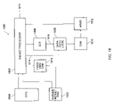
- FIG. 1 illustrates an embodiment 100 of a packet processing system comprising a packet classification system 102 and a packet modification system 104 .
- the packet classification system 102 has an ingress portion 106 and an egress portion 108 .
- the packet modification system 104 has an ingress portion 110 and an egress portion 112 .
- the ingress portion 106 of the packet classification system 102 is coupled, through interface 118 , to one or more network-side devices 114
- the egress portion 108 of the packet classification system 102 is coupled, through interface 120 , to one or more switch-side devices 116 .
- the ingress portion 110 of the packet modification system 104 is coupled, through interface 122 , to the one or more switch-side devices 116 , and the egress portion 124 of the packet modification system 104 is coupled, through interface 112 , to the one or more network-side devices 114 .
- the packet classification system 102 comprises an ingress portion 106 , a first packet parser 126 for parsing a packet and providing first data representative thereof, and a packet classification engine 128 for classifying the packet responsive to the first data.
- the packet modification system 104 comprises a second packet parser 130 for parsing the classified packet (after a round trip through the one or more switch-side devices 116 ) or a packet derived there-from and providing second data representative thereof, a packet modification engine 132 for modifying some or all of the packet responsive to the second data, a third packet parser 134 for parsing the modified packet and providing third data representative thereof, and a packet post-processor 136 for post-processing the modified packet responsive to the third data.
- the packet undergoing processing by the system has a plurality of encapsulated layers, and each of the first, second and third parsers 126 , 130 , 134 is configured to parse the packet by providing context pointers pointing to the start of one or more of the encapsulated layers.
- the packet undergoing processing by the system comprises a first packet forming the payload portion of a second packet, each of the first and second packets having a plurality of encapsulated layers, and each of the first, second and third parsers 126 , 130 , 134 is configured to parse the packet by providing context pointers pointing to the start of one or more of the encapsulated layers of the first packet and one or more of the encapsulated layers of the second packet.
- the packet post-processor 136 is configured to compute a checksum for a modified packet responsive to the third data provided by parser 134 . In one embodiment, the packet post-processor 136 is configured to independently calculate a layer three (IP) and layer four (TCP/UDP) checksum.
- IP layer three
- TCP/UDP layer four
- packet post-processor 136 comprises Egress Access Control List (ACL) logic 136 a and Packet Marking logic 136 b .
- the Egress ACL logic 136 a is configured to arrive at an ACL decision with respect to a packet.
- four ACL decisions can be independently performed: 1) default ACL action; 2). CPU copy; 3) mirror copy; and 4) kill.
- the default ACL action may be set to kill or allow.
- the CPU copy action forwards a copy of the packet to a host 138 coupled to the system.
- the mirror copy action implements an egress mirroring function (to be discussed in more detail later), in which a copy of the packet is forwarded to mirror FIFO 140 and then on to the egress portion 108 of the packet classification system 102 .
- the kill action either kills the packet or marks it for killing by a downstream Medium Access Control (MAC) processor.
- MAC Medium Access Control
- the Packet Marking logic 136 b is configured to implement a packet egress marking function in which certain packet marking control information for a packet generated by the packet classification system 102 is used to selectively modify one or more quality of service (QoS) fields in the packet.
- QoS quality of service
- Content Addressable Memory (CAM) 142 is used by the packet classification system 102 to perform packet searches to arrive at a classification decision for a packet.
- the CAM searches are ternary in that all entries of the CAM have a data and mask field allowing don't care setting of any bit position in the data field.
- the CAM searches are binary, or combinations of binary and ternary.
- the associated RAM (ARAM) 144 provides associated data for each entry in the CAM 142 .
- the ARAM 144 is accessed using the match address returned by the CAM 142 as a result of a search operation.
- the ARAM 144 entry data is used to supply intermediate classification information for the packet that is used by the classification engine 128 in making a final classification decision for the packet.
- the statistics RAM 146 is used to maintain various packet statistics, including, for each CAM entry, the cumulative number and size of packets that hit or matched that entry.
- the modification RAM 148 provides data and control structures for packet modification operations performed by the modification engine 132 .
- the interfaces 150 , 152 , 154 , and 156 with any of the RAMs or CAMs may be a QDR- or DDR-type interface as described in U.S. patent application Ser. No. 10/655,742, filed Sep. 4, 2003, which is hereby fully incorporated by reference herein as though set forth in full.
- FIG. 2 illustrates the format of classification data 200 for a packet as produced by one embodiment of packet classification system 102 .
- the classification data 200 in this embodiment has first and second portions, identified respectively with numerals 202 and 204 .
- the first portion 202 is a 64 bit Address Filtering Header (AFH) which is pre-pended to the packet.
- the second portion 204 is a 20 bit grouping of flags that are encoded as control bits maintained by the system 100 .
- AMFH Address Filtering Header
- the Port Tag Index (PTI) field is an identifier of the port or list of ports within interface 124 over which the packet will be sent by the packet modification engine. (The assumption in this embodiment is that the interface 124 is a multi-port interface).
- the Egress Quality of Service (EQoS) field may be used to perform an egress queue selection function in a device encountering the packet.
- this field also encodes one of the following functions: nothing, pre-emptive kill, normal kill, thermonuclear kill, egress mirror copy, pre-emptive intercept to host, and normal intercept to host.
- the Link Aggregation Index (LAI) field may be used to implement physical link selection, ingress alias, echo kill alias, or equal cost multi-path functions in a device encountering the packet.
- the JUMBO flag if asserted, directs a device encountering the packet to perform a JUMBO-allowed check.
- the flag is used to implement the policy that the only valid JUMBO packets are IP packets. Therefore, if the packet is a non-IP JUMBO packet, the device either sends it to a host, fragments it, or kills it.
- the DON'T FRAG flag if asserted, directs a device encountering the packet not to fragment it in the course of implementing a JUMBO-allowed check.
- the IF TYPE flag indicates whether the ingress interface over which the packet was received is an Ethernet or Packet Over Sonet (POS) interface.
- the ROUTE flag if asserted, indicates that the packet is being bridged not routed, and may be used by devices encountering the packet to implement an echo kill suppress function.
- the RANDOM EARLY DROP (RED) flag may be used to implement a random early drop function in devices encountering the packet.
- the CTL flag indicates the format of the AFH.
- FIG. 2 illustrates the format of the header for packets exiting the packet classification system 102 and destined for the one or more switch-side devices 116 .
- Another format applies for packets exiting the one or more switch-side devices 116 and destined for the packet modification system 104 .
- the CTL flag indicates which of these two formats is applicable.
- TXMI Transmit Modification Index
- the CPU Quality of Service (CQoS) field may be used to perform an ingress queue select function in a host coupled to the packet processing system.
- the CPU Copy flag if asserted, directs one or more of the switch-side devices 116 to forward a copy of the packet to a host coupled to the packet processing system. In another embodiment, the CPU Copy flag, if asserted, directs a copy of a packet to be forwarded to the host through a host bus or another PBUS.
- the Redirect flag if asserted, directs one or more of the switch-side devices 116 to forward a copy of the packet to the host for redirect processing.
- redirect processing the host receives the packet copy and redirects it to the sender, with an indication that the sender should switch the packet, not route it.
- the Statistical Sample (SSAMPLE) flag indicates to one or more of the switch-side devices 116 that the packet is a candidate for statistical sampling. If the packet is ultimately selected for statistical sampling, a copy of the packet is directed to the host, which performs a statistical analysis of the packet for the purpose of accurately characterizing the network traffic of which the packet is a part.
- the LEARN flag if asserted, directs one or more of the switch-side devices 116 to forward a copy of the packet to the host so the host can perform learn processing. In learn processing, the host analyzes the packet to “learn” the sender's MAC address for future packet switching of packets to that address.
- the Egress Mirror (EMIRROR) flag if asserted, implements egress mirroring by directing one or more of the switch-side devices 116 to send a copy of the packet to mirror FIFO 140 . From mirror FIFO 140 , the packet passes through the egress portion 108 of the packet classification system 102 en route to the one or more switch-side devices 116 .
- EMIRROR Egress Mirror
- the Ingress Quality of Service (IQoS) field may be used to perform an ingress queue selection function in a device encountering the packet.
- IQoS Ingress Quality of Service
- the Egress Mark Select (EMRK SEL) field selects one of several possible egress mark functions.
- the Egress Mask (EMRK MASK) field selects one of several possible egress masks. Together, the EMRK SEL and EMRK MASK fields forms an embodiment of packet egress marking control information which may be used by packet marking logic 136 b to mark the packet, i.e., selectively modify one or more QoS fields within the packet.
- the Ingress Mirror (IMIRROR) flag if asserted, directs one or more of the switch-side devices 116 to forward a copy of the packet to the designated ingress mirror port on the switch.
- the Parity Error Kill (PERR KILL) flag if asserted, directs the interface 120 to kill the packet due to detection of an ARAM parity error.
- the EMIRROR bit is normally in an unasserted state. If the packet classification system 102 , after analyzing the packet, determines that egress mirroring of the packet is appropriate, the packet classification system 102 changes the state of the EMIRROR bit to place it in the asserted state.
- the packet along with a pre-pended AFH containing the EMIRROR bit, is then forwarded to the one or more switch-side devices 116 .
- the one or more devices transmit the packet, with the EMIRROR bit preserved in a pre-pended packet header, back to the packet modification system 104 over interface 122 .
- the packet modification system 104 is configured to detect the state of the EMIRROR bit to determine if egress mirroring of the modified packet is activated, and if so, provide a copy of the modified packet to the egress portion 108 of the packet classification system 102 through the mirror FIFO 140 .
- the EQoS, CQoS, IQoS, EMRK SEL and EMRK MASK fields define a multi-dimensional quality of service indicator for the packet.
- the EMRK SEL and EMRK MASK fields form packet egress marking control information that is utilized by packet modification system 104 to selectively modify one or more quality of service fields within the packet, or a packet derived there-from.
- the quality of service indicator for a packet may be derived from a plurality of candidate quality of service indicators derived from diverse sources.
- a plurality of candidate quality of service indicators are derived for a packet, each with an assigned priority, and a configurable priority resolution scheme is utilized to select one of the plurality of quality of service indicators for assigning to the packet.
- one or more of the candidate quality of service indicators, and associated priorities are derived by mapping one or more fields of the packet into one or more candidate quality of service indicators for the packet and associated priorities.
- one or more searches are conducted to obtain one or more candidate quality of service indicators for the packet and associated priorities.
- a combination of these two approaches is utilized.
- candidate quality of service indicators, and associated priorities are derived from three sources.
- the first is a VLAN mapping scheme in which a VLAN from the packet is mapped into a candidate quality of service indicator and associated priority using a VLAN state table (VST).
- VST VLAN state table
- the VLAN from the packet may represent a subnet or traffic type, and the associated priority may vary based on the subnet or traffic type.
- the second is a CAM-based search that yields an associated ARAM entry that in turn yields a candidate quality of service indicator.
- a field of an entry in a Sequence Control Table (SCT) RAM which provides the sequence of commands controlling the operation of one embodiment of the packet classification engine 102 , provides the associated priority.
- SCT Sequence Control Table
- the third is a QoS mapping scheme, which operates in one of three modes, as determined by a field in a SCT RAM entry.
- the VST provides the four QSEGment bits.
- the QSEG and the 0.1 p bits are mapped into a candidate quality of service indicator, and the VLAN itself is mapped into an associated priority using the VST.
- the MPLS mapping mode the EXP/QOS fields from the packet are mapped into a candidate quality of service indicator, and a VLAN from the packet is mapped into the associated priority using the VST.
- the ToS mapping mode the IPv4 ToS, IPv6 Traffic Class, or Ipv6 Flow Label based QoS fields are mapped into a candidate quality of service indicator, and a VLAN from the packet is mapped into an associated priority using the VST.
- the candidate quality of service indicator with the highest priority is assigned to the packet.
- a candidate from one of the sources can be established as the default, which may be overridden by a candidate obtained from one of the other sources, at least a candidate that has a higher priority than the default selection.
- the candidate quality of service indicator resulting from the 0.1 p mapping mode can be established as the default selection, and this default overridden only by a candidate quality of service indicator resulting from an ARAM entry in turn resulting from a CAM-based search.
- FIG. 3 illustrates an embodiment 300 of a packet classification system.
- the packet classification system is coupled to one or more network-side devices through a multi-port packet bus (PBUS) 302 , as described in U.S. patent application Ser. Nos. 10/405,960 and 10/405,961, filed Apr. 1, 2003, which are both hereby fully incorporated herein by reference.
- PBUS ingress logic 304 is configured to detect a start of packet (SOP) condition for packets arriving at the packet classification system over the PBUS.
- SOP start of packet
- the packet, or a portion thereof is stored in slicer 306 .
- Slicer 306 is configured to slice some or all of a packet into portions and provide the portions in parallel over first data path 308 having a first width to classification engine 310 .
- the slicer 306 is a FIFO which stores the first 128 bytes of a packet (or the entirety of the packet if less than 128 bytes), and provides the 1024 bits thereof in parallel to the packet classification engine 310 over the first data path 308 .
- parser 312 parses the packet in the manner described previously, and stores the resultant context pointers (and other flags resulting from the parsing process) in parser result RAM 314 . Concurrently with this parsing process, the packet is stored in buffer 318 , which in one embodiment, is a FIFO buffer.
- the packet classification engine 310 is configured to classify the packet responsive to the packet portions received over the first data path 308 and the parser results as stored in the parser result RAM 314 , and store data representative of the packet classification in classification RAM 316 .
- the classification data is the AF header illustrated in FIG. 2 .
- An associator 320 is configured to associate the data representative of the packet classification with some or all of the packet, and provide the associated packet over a second data path 322 having a second width less than the first width.
- the packet classification system is coupled to one or more switch-side devices over a multi-port PBUS 326 , and PBUS egress logic 324 is configured to transmit the associated packet over the PBUS 326 .
- slicer 306 comprises a plurality of memories configured to store some or all of the packet, and provide the portions thereof in parallel over the first data path 308 to the classification engine 310 .
- the slicer 306 is configured as eight (8) memories configured to provide the first 1024 bits of the bits of the packet (or less if the packet is less than 128 bytes) in parallel over the first data path 308 to classification engine 310 .
- the associator 320 comprises a multiplexor configured to multiplex onto the second data path 322 the data representative of the packet classification as stored in classification RAM 316 and some or all of the packet as stored in buffer 318 .
- the multiplexor multiplexes the first 8 byte portion 202 of the AF data illustrated in FIG. 2 (which may be referred to as the AF header) onto the second data path followed by the packet as stored in buffer 318 , thereby effectively pre-pending the AF header to the packet.
- control logic 328 controls the operation of the multiplexor through one or more signals provided over control data path 334 .
- the multiplexor in this implementation is configured to select one of three inputs and output the selected input to the second data path 322 under the control of the control logic 328 .
- the first input is the classification data as stored in classification RAM 316 .
- the second input is the packet as stored in buffer 318 .
- the third input is the output of the mirror FIFO 140 . This third input is selected when the egress mirroring function, discussed previously, is activated.
- control logic 328 is also configured to maintain first and second FIFO buffers, identified respectively with numerals 330 and 332 , the first FIFO buffer 330 for identifying those packets which are awaiting classification by the packet classification system, and the second FIFO buffer 332 for identifying those packets which are undergoing classification by the classification system.
- control logic 328 is configured to place an identifier of a packet on the first FIFO buffer 330 upon or after receipt of the packet by the packet classification system, pop the identifier off the first FIFO buffer 330 and place it on the second FIFO buffer 332 upon or after initiation of classification processing of the packet by the packet classification system, and pop the identifier off the second FIFO buffer 332 upon or after completion of classification processing of the packet by the packet classification system.
- the control logic 328 is configured to prevent the packet classification system from outputting a packet onto PBUS 326 while an identifier of the same is placed on either the first or second FIFO buffers 330 , 332 , and allows the packet classification system to output the packet onto PBUS 326 upon or after the identifier of the packet has been popped off the second FIFO buffer 332 .
- the control logic 328 prevents the associator 320 from outputting data on the second data path 322 through one or more signals provided over control data path 334 .
- the control logic 328 is a state machine.
- control logic 328 forms the basis of a packet statistics maintaining system within the packet classification system.
- control logic 328 is configured to maintain a pool of packet size determiners, and allocate a packet size determiner to a packet from the pool upon or after receipt thereof by the packet classification system.
- control logic 328 allocates a packet size determiner to a packet upon or after the PBUS ingress logic 304 signals a SOP condition for the packet.
- the packet size determiner is configured to determine the size of the packet, and the control logic 328 is configured to return the packet size determiner to the pool upon or after the same has determined the size of the packet.
- the packet size determiners are counters.
- Statistics RAM 330 in this embodiment maintains packet statistics, and statistics update logic 336 is configured to update the packet statistics responsive to the determined size of the packet.
- the statistics update logic 336 includes a queue for queuing statistics update requests issued by the control logic 328 .
- the packet statistics maintaining system is configured to maintain packet statistics indicating the cumulative size of packets which have met specified processing conditions or hits
- the statistics update logic 336 upon or after a packet size determiner has determined the size of a packet, is configured to increment a cumulative size statistic for a particular processing condition or hit by the determined size of the packet if the packet satisfies that particular processing condition or hit.
- the system maintains statistics indicating the cumulative size and number of packets that have resulted in each of a plurality of ternary CAM 142 hits.
- FIGS. 4A-4B illustrate an embodiment 400 of a packet modification system having PBUS ingress logic 404 that is coupled to one or more switch-side devices through PBUS 402 .
- the packets are received over the PBUS channels in bursts.
- the PBUS ingress logic 404 is configured to monitor the PBUS channels in a round robin fashion.
- the Transmit Modification Index (TXMI) is extracted from the AF header of the packet, and it, along with the length of the initial packet burst, and an end of packet (EOP) marker if the packet length is less than or equal to the burst length, is placed on Transmit In Control FIFO 406 .
- the packet or packet burst is stored in Transmit In Data FIFO 428 , and a pointer to the start of the packet or packet burst (SOP pointer) is stored in Transmit Engine FIFO 408 , along with an identifier of the PBUS channel over which the packet or packet burst was received.
- the packet bursts are 128 bytes in length.
- Transmit In Data FIFO 428 stores the packet data such that portions of the packet can be passed in parallel over a first data path 402 having a first width to a modification engine 422 .
- the Transmit In Data FIFO 428 comprises a plurality of FIFOs, with the outputs of the FIFOs coupled in parallel to the modification engine 422 and collectively forming the first data path 402 .
- Incoming packet or packet bursts are copied into each of the plurality of FIFOs, thereby providing the modification engine with sliced portions of the packets or packet bursts in parallel.
- the incoming packets or packet bursts are also input to the second packet parser 424 , which parses the packets or packet bursts in the manner described previously.
- the context pointers and status bits resulting from the parsing process are stored in parser result RAM 426 .
- the Transmit Command Sequencer 410 is configured to read a SOP pointer and channel from the Transmit Engine FIFO 408 , and utilize this information to locate the packet or packet bursts in the Transmit In Control FIFO 406 .
- the Transmit Modification Index (TXMI) within the AF header of this packet or packet burst is then located and used to access a TXMI link in External Transmit SRAM 412 , an SRAM located off-chip in relation to modification engine 422 .
- TXMI Transmit Modification Index
- the TXMI link may either be 1) an internal recipe link to a recipe of modification commands stored in Internal Recipe RAM 414 , an on-chip RAM in relation to modification engine 422 , and related data structures stored in External Transmit SRAM 412 , or 2) an external recipe link to a recipe of modification commands stored in External Transmit SRAM 412 and related data structures also stored in External Transmit SRAM 412 .
- the sequencer 410 also assigns a sequence number to the packet to prevent packet re-ordering. It then directs the Transmit RAM arbiter 416 to read the recipe of modification commands stored in the External Transmit SRAM 412 (assuming the TXMI link is an external recipe link) or Internal Recipe RAM 414 (assuming the TXMI link is an internal recipe link) and store the same in Recipe RAM 418 , an on-chip RAM in relation to modification engine 422 . It further directs the arbiter 416 to read the data structures associated with the specified internal or external recipe command sequence, and store the same in Data RAM 420 , another on-chip RAM in relation to modification engine 422 .
- the sequencer 410 then awaits an available slot in the pipeline of the modification engine 422 . When such is available, the sequencer 410 passes to the engine 422 for placement in the slot a pointer to the recipe as stored in Recipe RAM 418 and other related information.
- the sequencer 410 assigns a fragment buffer to the packet.
- the fragment buffer is a buffer within a plurality of fragment buffers which collectively may be referred to as TX work buffer 436 .
- the modification engine then executes the recipe for the packet or packet burst, through one or more passes through the modification engine pipeline.
- the recipe comprises one or more entries, and one or more passes through the pipeline are performed to execute each entry of the recipe.
- the modification engine 422 stores the modified fragments of the packet in the fragment buffer allocated to the packet in TX work buffer 436 . At the same time, the modification engine 422 stores, in ascending order in fragment format RAM 438 , pointers to the modified fragments of the packet as stored in the fragment buffer and pointers to the unmodified fragments of the packet as stored in Transmit In Data FIFO 428 .
- the modification engine 422 When all the recipe entries have been executed, the modification engine 422 writes an entry to the fragment CAM 440 , the entry comprising the PBUS channel over which the packet was received, the sequence number for the packet, the SOP pointer to the packet (as stored in the Transmit In Data FIFO 428 ), a packet to be filled flag, a packet offset in the Transmit In Data FIFO 428 , and the total length of the list of fragments as stored in the fragment format RAM 438 . This completes the processing of the packet by the modification engine 422 .
- Fragment/burst processor 442 assembles the packets for ultimate egress from the system. To prevent packet re-ordering, the fragment/burst processor 442 processes, for each PBUS channel, the packets in the order in which they were received by the modification system 400 . More specifically, the fragment/burst processor 442 maintains an expected next sequence number for each PBUS channel, and then performs, in round robin fashion, CAM searches in fragment CAM 440 for an entry bearing the expected next sequence number for the channel. If an entry is found with that sequence number, the fragment/burst processor 442 processes it. If such an entry is not found, the fragment/burst processor 442 takes no action with respect to the channel at that time, and proceeds to process the next channel.
- the fragment/burst processor 442 directs assembler 446 to assemble the packet responsive to the fragment list for the packet as stored in the fragment format RAM 438 .
- the assembler 446 is a multiplexor, which is directed to multiplex between outputting on second data path 444 , responsive to the fragment list, the modified packet fragments as stored in the TX work buffer 436 and the unmodified packet fragments as stored in the Transmit In Data FIFO 428 (as provided to the multiplexor 446 over data path 434 ).
- the packet is assembled in ascending order on second data path 444 .
- the second data path 444 has a width less than the width of the first data path 402 .
- the fragment/burst processor 442 outputs the packets over data path 444 in the form of bursts.
- the assembled packet is parsed by the third packet parser 448 in the manner described previously.
- the resultant context pointers and status flags are then passed, along with the packet, for concurrent processing by Transmit Processor Block 452 and Transmit ACL Logic 454 .
- the Transmit Processor Block 452 performs two main functions. First, it performs egress mark processing by selectively modifying one or more QoS fields in the packet responsive to the egress mark control information from the packet stored by the modification engine in Transmit Post Processor RAM 456 . In one example, any of the VLAN VPRI, MPLS EXP, and IPv4/IPv6 TOS fields may be modified through this process utilizing the VPRI/EXP/IPToS RAMs 458 as appropriate.
- the egress mark control information may be derived from one or more egress mark commands specified by an AFH pre-pended to the packet, or from one or more egress mark commands within a recipe for the packet. Second, it performs OSI Layer 3/Layer 4 checksum calculation or modification.
- the Transmit ACL logic 454 conducts a CAM search for the packet in Egress ACL CAM 460 to determine if the packet should be killed, a copy sent to the host, or mirrored to the egress mirror FIFO 140 .
- the packet then exits the packet modification system 400 through the egress portion 462 of the system 400 , and is output onto PBUS 464 .
- FIG. 5 illustrates a cascaded combination 500 of multiple, replicated packet systems, each of which is either a packet classification system or a packet modification system.
- the cascaded combination comprises a first one 502 of the replicated packet systems having ingress and egress portions, identified respectively with numerals 504 and 506 , and a second one 508 of the replicated packet systems having ingress and egress portions, identified respectively with numerals 510 and 512 .
- the egress portion 506 of the first packet system 502 is coupled to the ingress portion 510 of the second packet system 508 .
- the first one 502 of the replicated packet systems is configured to perform partial processing of a packet, either classification or modification processing as the case may be, and the second one 508 of the replicated packet systems is configured to complete processing of the packet.
- packet system 508 forms the last one of a plurality of systems in the cascaded combination, and packet system 502 forms either the first or the next to last one of the systems in the cascaded combination.
- each of the replicated systems performs a limited number of processing cycles, and the number of replicated systems is chosen to increase the number of processing cycles to a desired level beyond that achievable with a single system.
- a complete set of processing functions or tasks is allocated amongst the replicated systems.
- a first replicated system is allocated ACL and QoS classification processing tasks
- a second replicated system is allocated PTI/TXMI classification processing tasks.
- FIG. 6 is a flowchart of one embodiment 600 of a method of processing a packet.
- the method comprises step 602 , parsing a packet and providing first data representative thereof, and step 604 , classifying the packet responsive to the first data.
- Step 606 the packet is forwarded to and received from switching fabric, which may perform additional processing of the packet.
- Step 608 comprises parsing the packet received from the switching fabric (which may be the packet forwarded to the switching fabric, or a packet derived there-from), and providing second data representative thereof.
- Step 610 comprises modifying the packet responsive to the second data
- step 612 comprises parsing the modified packet and providing third data representative thereof.
- Step 614 comprises post-processing the modified packet responsive to the third data.
- the packet undergoing processing has a plurality of encapsulation layers, and each of the first, second and third parsing steps 602 , 608 , 612 comprising providing context pointers pointing to the start of one or more of the encapsulated layers of the packet.
- the packet undergoing processing comprises a first packet forming the payload portion of a second packet, each of the first and second packets having a plurality of encapsulation layers, and each of the first, second and third parsing steps 602 , 608 , 612 comprises providing context pointers pointing to the start of one or more of the encapsulated layers of the first packet and one or more of the encapsulated layers of the second packet.
- the post-processing step comprises computing a checksum for the modified packet.
- the post-processing step comprises egress marking of the packet.
- the post-processing step comprises the combination of the foregoing two implementations.
- FIG. 7 is a flowchart of a second embodiment 700 of a method of processing a packet.
- step 702 comprises analyzing a packet in a packet classification system and, responsive thereto, selectively changing the state of a control bit from a first state to a second state.
- step 704 comprises forwarding the packet to and from switching fabric.
- Step 706 comprises modifying, in a packet modification system, the packet received from the switching fabric (either the packet forwarded to the switching fabric, or a packet derived there-from), detecting the control bit to determine if egress mirroring of the modified packet is activated, and if so, providing a copy of the modified packet to the packet classification system.
- control bit is associated with the packet received from the switching fabric. In one example, the control bit is in a packet header pre-pended to the packet received from the switching fabric.
- FIG. 8 is a flowchart of a third embodiment 800 of a method of processing a packet.
- Step 802 comprises providing a multi-dimensional quality of service (QoS) indicator for a packet.
- Step 804 comprises forwarding the packet to and from switching fabric.
- Step 806 comprises egress marking of the packet received from the switching fabric (either the packet forwarded to the switching fabric, or a packet derived there-from), responsive to at least a portion of the multi-dimensional QoS indicator.
- QoS quality of service
- step 806 comprises selectively modifying one or more quality of service fields within the packet received from the switching fabric responsive to at least a portion of the multi-dimensional quality of service indicator.
- the multi-dimensional quality of service indicator comprises an ingress quality of service indicator, an egress quality of service indicator, and packet marking control information
- step 806 comprises selectively modifying one or more quality of service fields within the packet received from the switching fabric responsive to the packet marking control information.
- the multi-dimensional quality of service indicator further comprises a host quality of service indicator.
- the method further comprises utilizing the ingress quality of service indicator as an ingress queue select. In a second embodiment, the method further comprises utilizing the egress quality of service indicator as an egress queue select. In a third embodiment, the method further comprises utilizing the host quality of service indicator as an ingress queue select for a host.
- FIG. 9 is a flowchart of an embodiment 900 of assigning a quality of service indicator to a packet.
- step 902 comprises providing a plurality of quality of service indicators for a packet, each with an assigned priority
- step 904 comprises utilizing a configurable priority resolution scheme to select one of the plurality of quality of service indicators for assigning to the packet.
- step 902 comprises mapping one or more fields of the packet into a quality of service indicator for the packet and an associated priority.
- step 902 comprises performing a search to obtain a quality of service indicator for the packet and an associated priority.
- a third implementation comprises a combination of the foregoing two implementations.
- FIG. 10 is a flowchart of an embodiment 1000 of a method of classifying a packet.
- step 1002 comprises slicing some or all of a packet into portions and providing the portions in parallel over a first data path having a first width to a classification engine.
- step 1004 comprises classifying, in the packet classification engine, the packet responsive to the packet portions received over the first data path and providing data representative of the packet classification.
- Step 1006 comprises associating the data representative of the packet classification with the packet to form an associated packet, and providing the associated packet over a second data path having a second width less than the first width.
- the step of providing the packet portions over the first data path comprises providing each of the bits of some or all of the packet in parallel over the first data path to the classification engine.
- the associating step comprises multiplexing the data representative of the packet classification and some or all of the packet onto the second data path.
- FIG. 11 is a flowchart of an embodiment 1100 of a method of modifying a packet.
- Step 1102 comprises providing some or all of a packet as packet portions and providing the portions in parallel over a first data path having a first width to a modification engine.
- Step 1104 comprises modifying, in the modification engine, one or more of the packet portions.
- Step 1106 comprises assembling a packet from the one or more modified and one or more unmodified packet portions, and providing the assembled packet over a second data path having a second width less than the first width.
- FIG. 12 is a flowchart 1200 of an embodiment of a method of classifying a packet.
- Step 1202 comprises placing an identifier of a packet on a first FIFO buffer.
- Step 1204 comprises popping the identifier off the first FIFO buffer and placing it on a second FIFO buffer upon or after initiation of classification processing of the packet.
- Step 1206 comprises avoiding outputting the packet while an identifier of the same is placed on either the first or second FIFO buffers.
- Step 1208 comprises outputting the packet upon or after the identifier of the packet has been popped off the second FIFO buffer.
- FIG. 13 is a flowchart illustrating an embodiment 1300 of a method of maintaining packet statistics.
- Step 1302 comprises allocating a packet size determiner to a packet from a pool of packet size determiners.
- Step 1304 comprises using the packet size determiner to determine the size of the packet.
- Step 1306 comprises updating one or more packet statistics responsive to the determined size of the packet.
- Step 1308 comprises returning the packet size determiner to the pool upon or after the same has determined the size of the packet.
- the packet size determiner is a counter that counts the size of the packet.
- the method further comprises queuing one or more statistics update requests.
- the one or more packet statistics indicate the cumulative size of packets which have met specified processing conditions or hits
- step 1306 comprises incrementing a cumulative size statistic for a particular processing condition or hit by the determined size of the packet if the packet meets that particular processing condition or hit.
- FIG. 14 illustrates an embodiment 1400 of a method of classifying a packet.
- Step 1402 comprises buffering a packet in a buffer upon or after ingress thereof.
- Step 1404 comprises classifying the packet and providing data representative of the packet classification.
- Step 1406 comprises associating the data representative of the packet classification with some or all of the packet as directly retrieved from the buffer to form a packet on an egress data path.
- step 1406 comprises multiplexing the data representative of the packet classification onto a data path followed by some or all of the packet as directly retrieved from the buffer.
- FIG. 15 illustrates an embodiment 1500 of a method of modifying a packet.
- Step 1502 comprises buffering the packet in a buffer upon ingress thereof.
- Step 1504 comprises modifying one or more portions of the packet.
- Step 1506 comprises assembling the one or more modified portions of the packet with one or more unmodified portions of the packet as retrieved directly from the buffer to form an assembled packet on an egress data path.
- the method comprises providing a list indicating which portions of the assembled packet are to comprise modified portions of an ingress packet, and which portions are to comprise unmodified portions of the ingress packet, and step 1506 comprises assembling the assembled packet responsive to the list.
- FIG. 16 illustrates an embodiment 1600 of a method of processing a packet in a cascaded combination of multiple, replicated packet processing systems.
- each of systems is either a packet classification system or a packet modification system, and the processing which is performed by each system is either classification processing or modification processing as the case may be.
- Step 1602 comprises performing partial processing of a packet in a first of the replicated packet processing systems
- step 1604 comprises completing processing of the packet in a second of the replicated packet processing systems.
- the second packet processing system is the last of a plurality of replicated packet processing systems
- the first packet processing system is either the first or next to last packet processing system in the plurality of packet processing systems, wherein partial processing of a packet is performed in the first replicated packet processing system, and processing is completed in the second replicated packet processing system.
- FIG. 17 illustrates an embodiment 1700 of a method of preventing re-ordering of packets in a packet processing system.
- Step 1702 comprises assigning a sequence number to a packet upon or after ingress thereof to the system.
- Step 1704 comprises processing the packet.
- Step 1706 comprises storing data representative of the packet in a buffer.
- Step 1708 comprises checking the buffer for an entry matching an expected next sequence number.
- Inquiry step 1710 comprises determining if a match is present. If so, steps 1712 and 1714 are performed.
- Step 1712 comprises outputting the corresponding packet, and step 1714 comprises updating the expected next sequence number to reflect the outputting of the packet. If not, the method loops back to step 1708 , thus deferring outputting a packet if a match is not present.
- steps 1708 - 1714 comprise maintaining an expected next sequence number for each of a plurality of output channels, checking the buffer for a match for each of the channels, outputting the corresponding packet on a channel if a match for that channel is present and updating the expected next sequence number for that channel, and deferring outputting a packet on a channel if a match for that channel is not present.
- FIG. 18 An embodiment of a pipelined packet processing system 1800 is illustrated in FIG. 18 .
- the system 1800 comprises a packet processor 1802 that maintains at least one pipeline having a predetermined number of slots, such as illustrated in FIG. 19 , for placement of packet data. Three such slots are identified in FIG. 19 with numerals 1902 a , 1902 b , and 1902 c .
- the packet processor 1802 is configured to load each of one or more empty ones of the slots with available packet data, process each of one or more filled ones of the slots in sequence during a cycle of processing, and process each of the one or more filled ones of the slots for a predetermined number of cycles of processing.
- the processor 1802 is configured to process the data in a filled slot during a cycle by accessing one or more resources responsive to state data corresponding to the packet data stored in the slot, retrieving data from the one or more resources, and selectively updating the state data responsive to the data retrieved from the one or more resources.
- the processor 1802 Upon or after the data in the filled slot has undergone the predetermined number of cycles of processing, the processor 1802 is configured to unload the data, and derive packet classification or forwarding information from the state data for the packet. In one embodiment, the processor 1802 assigns the packet classification or forwarding information to the packet such as by pre-pending it to the packet.
- the processor 1802 forms the packet classification engine 128 illustrated in FIG. 1 , or the classification engine 310 illustrated in FIG. 3 , and the packet classification or forwarding information derived by the processor 1802 is the AFH, illustrated in FIG. 2 , which is pre-pended to the packet.
- the processor 1802 is configured to fill the one or more of the unfilled ones of the slots 1902 a , 1902 b , 1902 c during a loading mode of operation, and process one or more of the filled ones of the slots during a subsequent processing mode of operation that commences after the loading mode of operation has been completed.
- the processor 1802 is configured to fill the one or more of the unfilled slots with available packet data as obtained from a queue 1903 .
- the processor 1802 is configured to bypass unfilled ones of the slots if and while the queue is empty.
- filled ones of the slots are identified with “P” while unfilled ones of the slots are identified with “X.”
- the packet data that is taken from queue 1903 and stored in a slot is an identifier of packet data as stored in FIFO buffer 1804 .
- the queue 1903 is the queue 330 , illustrated in FIG. 3 , which maintains identifiers of packets that are awaiting classification, and the FIFO buffer 1804 is slicer 306 .
- working state data is stored in the slots along with the corresponding packet data.
- this working state data is shown in phantom and identified with numerals 1904 a , 1904 b , 1904 c.
- the predetermined number of slots maintained by the processor 1802 is a programmable variable having a default value of 20 slots, and the predetermined number of processing cycles that each slot undergoes is also a programmable variable having a default value of 5 cycles.
- identifiers of packets awaiting processing by processor 1802 are stored in the queue 1903 .
- each of the slots 1902 a , 1902 b , 1902 c in the pipeline are sequentially loaded with packet identifiers popped off the queue 1903 .
- the process of loading slots is identified in FIG. 19 with numeral 1906 .
- the processor enters a processing mode of operation, during which each of the filled slots undergoes the predetermined number of cycles of processing.
- the processor 1802 performs a cycle of processing on a slot by retrieving an entry from sequence control table (SCT) 1806 .
- SCT sequence control table
- the address of the command in the SCT is obtained from an entry in First Command CAM 1818 . That entry is obtained from a search of the First Command CAM 1818 using a key derived from the results of parsing the packet as stored in Parser Result RAM 1820 .
- the address of the command is obtained from working state data stored in the slot itself alongside the corresponding packet data. In one implementation, this address is stored in the slot at the conclusion of the previous cycle of processing. In one example, this address is derived during the previous cycle of processing from the SCT command that is being executed during that cycle of processing.
- the Parser Result RAM 1820 is the Parser Result RAM 314 identified in FIG. 3 .
- the command from SCT 1806 is processed by data path logic 1808 to form a key to CAM 1810 .
- a matching entry in the CAM 1810 is located. This matching entry identifies a corresponding entry in associated RAM (ARAM) 1812 .
- the ARAM and/or SCT entries either provide working state data for the packet undergoing processing, or provide data from which that working state data is updated.
- CAM 1810 forms the CAM 142 illustrated in FIG. 1
- ARAM 1812 forms the ARAM 144 illustrated in FIG. 1 .
- the steps of updating the working state information for a packet are reflected in FIG. 19 .
- the slot conceptually moves through the pipeline in a counter-clockwise fashion.
- SCT 1806 for the command to be executed.
- the address of this first command is obtained from First Command CAM 1818 .
- the address of the command is obtained from the working state for the packet stored in the slot alongside the packet.
- the SCT command resulting from this access is obtained.
- this command is processed by data path logic 1808 to result in a CAM key.
- an access is made to CAM 1810 using this key. Because of the latency of this CAM, the result of this access is not available until the point identified with numeral 1916 .
- the CAM entry resulting from this access is used to access a corresponding entry in ARAM 1812 .
- the result of this access is available.
- data resulting from the ARAM access and/or the SCT command data is resolved with the current working state data for the packet.
- an element of the ARAM/SCT data supersedes an existing element of state data if it has a higher priority.
- an element of the ARAM/SCT data may supersede an existing element of state data without regard to priority.
- the working state data for a packet is stored in the corresponding slot alongside the packet data.
- an identifier of the working state data as stored in a buffer is stored in the corresponding slot along with the packet data.
- the working state data for a packet is control data, such as, for example, pipeline management information, packet process state data, or static packet information.
- the working state data for a packet is packet classification or forwarding information for the packet such as, for example, priority-based packet classification/forwarding information or non-priority-based packet classification/forwarding information.
- the working state data for the packet is statistical information relating to the packet.
- the working state data for a packet is any combination of the foregoing.
- the working state data maintained for a packet comprises control data 2002 , AFH data 2004 , and statistical information 2006 .
- the working state data is stored in the slot along with an identifier of the packet as stored in a buffer (such as slicer 306 in FIG. 3 ).
- the control data 2002 comprises:
- the AFH data 2004 comprises:
- the statistical data comprises:
- the pipeline of FIG. 19 comprises three separate but related pipelines, identified with numerals 2102 , 2104 , 2106 in FIG. 21 , that are respectively used to update the control, AFH, and statistical portions of the working state data.
- FIG. 22 illustrates an implementation example of the control data portion of the state data corresponding to a packet
- FIG. 23 is an implementation example of the AFH portion of the state data corresponding to a packet
- FIG. 24 is the statistics data portion of the state data corresponding to a packet.
- the functions of the various bits and fields illustrated in FIG. 22 are as follows:
- the data of FIGS. 22 , 23 and 24 is consolidated with other data to form the process data illustrated in FIG. 25 .
- the control data of FIG. 22 forms the 116 bit CONTROL SET referred to in FIG. 25 ;
- the AFH data of FIG. 23 forms the 112 bit AFH SET referred to in FIG. 25 ;
- the statistics data of FIG. 24 forms the 56 bit STATS SET referred to in FIG. 25 .
- This process data which includes a pointer to the corresponding packet, forms the state data that is stored in a slot.
- the functions of the other fields referred to in FIG. 25 are as follows:
- the first cycle of processing is preceded by the following initialization steps of the CONTROL SET data:
- All the data in the AFH SET is initialized to 0.
- the data in the STATISTICS SET is initialized to values specified in the PST/VST table.
- a cycle of processing comprises the following steps:
- CAM 1810 is organized so that higher priority entries precede lower priority entries. If there are multiple matches or hits with the CAM key, the first such match or hit is selected, consistent with the higher priority of this entry compared to the other entries.
- the format of a SCT entry is as illustrated in FIGS. 28A-28C .
- the following elements of the SCT entry format of FIGS. 28A-28C are relevant to this discussion:
- the CAM key used to search through CAM 1810 during a processing cycle is derived by the data path logic 1808 of FIG. 18 from the process and packet data for that processing cycle, as well as the current SCT entry.
- the packet and process data is provided to the data path logic 1808 over one or more signal lines 1814
- selection data used to narrow the combined 256 bytes of data represented by this process and packet data down to the desired size of the CAM key, is provided to the data path logic 1808 from the current SCT entry over one or more signal lines 1816 .
- FIG. 29 illustrates one example 2900 of the data path logic 1808 .
- the data path logic produces a 72 bit CAM key 2902 that comprises 18 4-bit nibbles. Each of the nibbles is produced by a corresponding 4-bit wide multiplexor.
- nibble 0 of CAM key 2902 is produced by multiplexor 2904 a
- nibble 17 of CAM key 2902 is produced by multiplexor 2904 b .
- Each of these multiplexors receives the same inputs in the same order, 512 4-bit nibbles, 256 nibbles representing the process data, and 256 nibbles representing the packet data. Each of these multiplexors receives its own 12-bit selection field from the current SCT entry.
- multiplexor 2904 a receives the 12-bit SELECT 0 field, referred to in FIG. 28 as CAM KEY SEL NIBBLE 0
- multiplexor 2904 b receives the 12-bit SELECT 17 field, referred to in FIG. 28 as CAM KEY SEL NIBBLE 17
- There are a total of 18 selection fields represented in FIG. 28 which may be referred to respectively as CAM KEY SEL NIBBLE 0 - 17 , each of which is assigned its own multiplexor in the implementation of data path logic illustrated in FIG. 29 .
- FIG. 30 illustrates the format of each of these 12-bit selection fields.
- the functions performed by the bits and fields in this format are as follows:
- a 144 bit CAM key is formed using the structure of FIG. 29 from two successive retrievals of SCT entries over two successive half cycles.
- the selection fields from the two successive SCT entries are successively input to the multiplexors of FIG. 29 with the same process and packet data as inputs.
- two 72 data structures are formed that are concatenated to form the 144 bit CAM key.
- FIG. 31 illustrates several possible examples of 72 bit keys.
- the CAM key is used to search through CAM 1810 . If there is a hit, the process yields an ARAM entry.
- the format of an ARAM entry is as illustrated in FIGS. 32A-32B .
- the current SCT and/or ARAM entries yield data that is used to selectively update the state data for the slot.
- Other resources may be accessed as well for the purpose of retrieving data for use in updating the current state data as described in U.S. patent application Ser. No. 10/835,271, filed Apr. 28, 2004; U.S. patent application Ser. No. 10/834,576, filed Apr. 28, 2004.
- the state data for a slot is the process data illustrated in FIG. 25 .
- this process data is selectively updated at the conclusion of a processing cycle in the following order: CONTROL SET, AFH SET, and STATS SET.
- the CONTROL SET data is updated in part based on the ARAM field CONT UPDATE. As illustrated in FIG. 33 , this field, if non-zero, is used to select one of fifteen registers is register bank 3302 .
- a first predetermined bit 3304 a in the selected register 3303 forms the updated value of PAGE SEL.
- a second predetermined bit 3304 b in the selected register 3303 forms the updated value of VLAN SEL.
- a third predetermined bit 3304 c in the selected register 3303 forms the updated value of L3 SEL.
- one or more selected bits in the selected register 3303 may be used to selectively update specific context pointers to handle, for example, the situation in which the parser did not recognize the corresponding protocol and thus inaccurately determined the context pointer.
- the selected bit may be used to replace the selected context pointer with an updated value in this embodiment.
- the updated PAGE SEL, VLAN SEL, and L3 SEL values form part of the updated state data for the current slot, but they are used to update other portions of this state data, such as the context pointers C1-C6, and the working VLAN.
- An embodiment of multiplexing logic for updating this other state data which may be part of processor 1802 or data path logic 1808 , is illustrated in FIG. 34 .
- Numeral 3402 a identifies page 0 context information
- numeral 3404 b identifies page 1 context information.
- the page 0 context information comprises the C1-C6 context pointers, up to two VLANs, VLAN0 and VLAN1, and up to two nested L3 IP Headers, IPHDR0 and IPHDR1.
- the page 1 context information comprises the C1-C6 context pointers, up to two VLANs, VLAN0 and VLAN1, and up to two nested L3 IP Headers, IPHDR0 and IPHDR1.
- Multiplexor 3404 selects between these two groupings of information based on the value of PAGE SEL. If two L3 IP headers are present in the selected page, multiplexor 3410 selects between these two headers based in the value of L3 SEL. Similarly, if two VLANs are present in the selected page, multiplexor 3406 selects between these two VLANs based on the value of VLAN SEL. And multiplexor 3408 selects between the VLAN selected by multiplexor 3406 and any ARAM-supplied VLAN based on the value of REPLACE VLAN (from the ARAM entry).
- the output of multiplexor 3408 forms the updated working VLAN in the CONTROL SET portion of the process data.
- the selected C1-C6 context pointers output by multiplexor 3404 identified with numeral 3412 , form the updated C1-C6 context pointers in the CONTROL SET portion of the process data, except that the C3 context pointer may be modified if there are nested L3 headers in the selected page and the inner header is selected by multiplexor 3410 as the current L3 header. In that case, the C3 context pointer is updated to pointer to the inner L3 header.
- the value of LKUP COUNT in the CONTROL SET portion of the process data is incremented by one.
- the SCT field in this CONTROL SET representing the index of the next SCT entry, is updated using the logic illustrated in FIG. 35 , which may be part of the processor 1802 or the data path logic 1808 .
- multiplexor 3502 selects between the NEXT SCT HIT and NEXT SCT MISS values provided by the current SCT entry based on HIT, an indicator of whether there was a CAM hit or not. If a CAM hit occurred, NEXT SCT HIT is selected. If a CAM miss occurred, NEXT SCT MISS is selected.
- Multiplexor 3504 selects between the selected SCT-supplied next SCT index output by multiplexor 3502 and the ARAM-supplied next SCT index (NEXT SCT) based on the logical ANDing of HIT and the ARAM-supplied NEXT SCT VALID field. In other words, if there was a CAM hit and the ARAM-supplied next SCT index is valid, the ARAM-supplied next SCT index (NEXT SCT) is selected. Otherwise, the selected SCT-supplied next SCT index (output by multiplexor 3504 ) is selected. The selected value output by multiplexor 3504 forms the SCT field in the CONTROL SET portion of the process data.
- FIG. 36 illustrates an embodiment in which logic 3602 updates priority-based values within this AFH SET, such as PTI, IQoS, EQoS, CQoS, EMS/EMM, TXMI, and LAI.
- This logic which may either be part of processor 1802 or data path logic 1808 , is configured to updates the current value of a priority-based element 3604 , such as PTI or TXMI, if two conditions are met. First, if the next potential value 3606 of this element is valid. Second, if the priority 3608 of the next potential value exceeds the priority 3610 of the current value 3604 . If these two conditions are met, the next potential value 3606 replaces the current value 3604 in the state data, and the priority 3608 of the next potential value replaces the priority 3610 in the state data.
- a priority-based element 3604 such as PTI or TXMI
- the specific manner of updating several elements of the AFH SET proceeds as follows:
- FIG. 37 illustrates one embodiment 3700 of a method of performing pipelined processing of one or more packets in a pipeline having a predetermined number of slots for placement of packet data.
- the method comprises step 3702 , loading each of one or more empty ones of the slots of the pipeline with available packet data.
- the method further comprises step 3704 , processing the data in each of one or more filled ones of the slots in sequence during a cycle of processing, and also processing the data in each of one or more filled ones of the slots for a predetermined number of cycles of processing, occurs.
- the method further comprises step 3706 , unloading the data in each of one or more filled ones of the slots upon or after the data in the filled slot has undergone the predetermined number of cycles of processing, and deriving classification or forwarding information for the packet from related state information for the packet.
- the predetermined number of slots in the pipeline is fixed. In another embodiment, it is a programmed variable. In one implementation, the step of loading the pipeline comprises filling one or more unfilled ones of the slots with packet data as obtained from a queue. In one example, the step further comprises bypassing one or more unfilled ones of the slots if and while the queue is empty.
- the packet data loaded into a slot is an identifier of the packet as stored in a buffer.
- the state data relating to a packet is stored in a slot along with the packet data corresponding to the packet.
- the related state data for a packet is control data, such as pipeline management data, or packet process state data.
- control data is static packet information.
- the related state data is packet classification/forwarding information, such as priority-based packet classification/forwarding information or non-priority-based packet classification/forwarding information.
- the related state data may also comprises one or more “sticky” flags relating to the packet, or statistical information relating to the packet, including statistical information relating to each of a plurality of processing cycles performed on the corresponding packet data.
- FIG. 38 illustrates an embodiment 3800 of a method of processing the data in a filled slot of the pipeline during a processing cycle.
- the method comprises step 3802 , accessing one or more resources responsive to current working state data corresponding to the slot.
- the method also comprises step 3804 , retrieving data from one or more of the resources.
- this step comprises retrieving an SCT entry using an SCT index as obtained from the working state data, deriving a CAM key from this entry, using this CAM key to perform a CAM search. If the search results in a hit, a corresponding ARAM entry is retrieved.
- the data in the SCT and/or ARAM entries form the data retrieved in step 3804 .
- data from other resources besides the SCT and ARAM are retrieved in this step, including but not limited to QoS mapping tables, PST, VST or VPST tables, Exception Handlers, etc.
- the method further comprises step 3806 , selectively updating the working state data responsive to the data retrieved in step 3804 .
- FIG. 39 illustrates an embodiment 3900 of a system for deriving hash values for packets in a packet processing system.
- the system comprises key derivation logic 3902 for deriving a key 3904 from data 3906 representative of at least a portion of a packet, at least a portion of a state of the packet, or both.
- the key 3904 is configured to drive processing of the packet.
- the system also comprises packet processing logic 3908 for processing the packet responsive to the key 3904 , and hash derivation logic 3910 for deriving a hash value 3912 for the packet responsive to the key 3904 .
- This hash value is useful for supporting additional processing of the packet.
- the key derivation logic 3902 is configured to derive a key 3904 for each of a plurality of processing cycles
- the packet processing logic 3908 is configured to process the packet over the plurality of cycles
- the hash derivation logic 3910 is configured to derive a hash value for each of the cycles
- the system 3900 further comprises resolution logic 3914 for resolving the hash values derived during each of the plurality of processing cycles, resulting in a hash value 3916 for the packet.
- the processing logic 3908 comprises CAM 3918 , ARAM 3920 , SCT 3928 , a register 3922 holding the SCT entry for the current processing cycle, and addressing logic 3924 for determining the address of the SCT entry for the next processing cycle.
- the data path logic 3902 comprises the data path logic illustrated and described in relation to FIG. 29 ;
- CAM 3918 is the CAM 1810 illustrated and described in relation to FIG. 18
- ARAM 3920 is the ARAM 1812 illustrated and described in relation to FIG. 18
- SCT 3928 is the SCT 1806 illustrated and described in relation to FIG. 18 .
- Each SCT entry has the format illustrated in FIG. 28
- each ARAM entry has the format illustrated in FIGS.
- the addressing logic 3924 is configured to determine the address of the SCT entry that governs the next processing cycle. As shown, this logic is configured so that any ARAM-supplied SCT address (supplied by means of the NEXT SCT field of FIG. 30 ), becomes the next SCT address if such is valid, as indicated by assertion of the ARAM-supplied NEXT SCT VALID flag ( FIG. 30 ). Otherwise, the next SCT address is formed from corresponding entries in the current SCT entry 3922 . In particular, if there is a hit condition, the next SCT address becomes the SCT address specified by the NXT SCT HIT field ( FIG. 28 ); if there is a miss condition, the next SCT address becomes the SCT address specified by the NXT SCT MISS field ( FIG. 28 ).
- the key derivation logic 3902 has the form illustrated in FIG. 29 .
- the key is formed directly from the output of the key derivation logic 3902 .
- the key is formed from the concatenation of two successive outputs of the key derivation logic 3902 over two successive half cycles.
- the hash derivation logic 3910 has the form illustrated in FIG. 40 .
- Each 4-bit nibble of the key 2902 a , 2902 b , 2902 c is input to a corresponding AND gate, configured to allow the nibble to be masked through a corresponding mask, identified in FIG. 40 as MASK 0 , MASK 1 , MASK 17 .
- each of the masks is a single bit as obtained from the LA MSK field of the current SCT entry 3922 ( FIG. 28 ). This bit allows the entirety of the corresponding nibble to be masked or not, but does not allow individual bits of the nibble to be masked.
- the masked nibbles 4004 a , 4004 b are then logically combined through logical XOR gates 4004 a , 400 b in the manner shown, resulting in a 4-bit hash value 4006 .
- the hash value is formed by logically XORing the half values of the two cycles together.
- this logically XORing must be suppressed since the two values will be the same, and logically XORing them would result in 0.
- the hash value 3930 output by the hash derivation logic 3910 may be superseded by an ARAM-supplied hash value provided in the form of the LAI field ( FIG. 30 ).
- the ARAM-supplied LAI flag ( FIG. 30 ) indicates whether the ARAM-supplied LAI is valid or not. If so, logic 3926 is configured to substitute the ARAM-supplied value for the value 3930 at the output 3912 .
- Resolution logic 3914 is configured to resolve the values 3912 received over multiple processing cycles for a packet to result in a hash value 3916 for the packet.
- two modes are possible as determined by the LAI CTRL field of the current SCT entry ( FIG. 28 ).
- each value 3912 received during a processing cycle replaces the previous value. Consequently, at the conclusion of all the processing cycles for a packet, the hash value 3916 assigned to the packet is the hash value 3912 derived during the last processing cycle for the packet.
- the hash values 3912 from the various processing cycles are logically XORed together to result in the hash value 3916 for the packet.
- FIG. 39 should not be construed as limiting.
- the illustrated details of the processing logic 3918 are not important to the invention as broadly construed, and therefore should not be construed as limiting.
- the system 3900 further comprises link aggregation logic (not shown) for supporting a link aggregation function, which refers to the process of treating multiple physical links as one logical link, and then utilizing an egress distribution policy to distribute packets intended for the logical link over the physical links.
- link aggregation refers to the function of treating each of the physical links 4106 as a single logical link, thus giving rise to the need for a policy for distributing packets, to be transferred between the two devices over the logical link, amongst the physical links.
- a packet is allocated to a physical link based on the hash value assigned to the packet.
- the hash value may be referred to as a link index. It is assumed in this application that there is a 1-1 or many-to-1 relationship between the possible hash values and the physical links.
- the system of FIG. 39 further comprises equal cost multi-path logic (not shown) for supporting an equal cost multi-path function.
- equal cost multi-path logic (not shown) for supporting an equal cost multi-path function.
- a policy must again be devised for distributing the packets over the various equal cost paths.
- such a policy is implemented by modifying, responsive to the hash value for the packet, an egress port identifier for the packet derived by the packet processing logic 3908 .
- an identifier of a packet processing sequence assigned to the packet by the packet processing logic 3908 is also modified responsive to the hash value of the packet. This processing sequence specifies one or more packet processing operations to be performed on the packet prior to egress thereof by the packet processing system.
- the hash value comprises the 4 bit nibble discussed in relation to FIG. 40
- the equal cost multi-path function is implemented by directly replacing the lower four bits of the PTI assigned to the packet with the 4-bit hash value, and the lower four bits of the TXMI assigned to the packet with the 4 bit hash value.
- an indirect approach is utilized to modify the PTI and TXMI of the packet.
- the hash value (referred to as the LAI in FIG. 23 ) forms part of the key in the next processing cycle.
- an entry in the CAM is retrieved based on this key. This entry contains a PTI and TXMI value that is assigned to the packet.
- FIG. 43 is a flowchart of an embodiment 4300 of a method of deriving hash values for packets in a packet processing system.
- the method comprises step 4302 , deriving a key from data representative of at least a portion of a packet or at least a portion of a state of the packet.
- the key is configured to drive the processing of the packet.
- the method also comprises step 4304 , processing the packet responsive to the key.
- the method further comprises step 4306 , deriving a hash value for the packet responsive to the key, wherein the hash value is useful for supporting additional processing of the packet.
- the first deriving step 4302 comprises deriving a key for each of a plurality of processing cycles
- the processing step 304 comprises processing the packet over the plurality of cycles
- the second deriving step 4306 comprises deriving a hash value for each of the cycles
- the method further comprises resolving the hash values derived during each of the plurality of processing cycles, resulting in a hash value for the packet.
- the method further comprises supporting a link aggregation function by allocating the packet to one of a plurality of physical links comprising a logical link based on the hash value of the packet.
- the method further comprises supporting an equal cost multi-path function by modifying, responsive to the hash value for the packet, an egress port identifier for the packet derived during or responsive to the processing step.
- the method further comprises supporting an equal cost multi-path function by modifying an identifier of a packet processing sequence assigned to the packet during or responsive to the processing step 4304 , the processing sequence specifying one or more packet processing operations to be performed on the packet prior to egress thereof by the packet processing system.
- the method further comprises resolving the hash values for the plurality of processing cycles by substituting the hash value derived during a processing cycle for the hash value derived during a preceding processing cycle. In a second embodiment, the method further comprises resolving the hash values for the plurality of processing cycles by logically combining these hash values into a hash value for the packet.
- any of the foregoing systems and methods may be implemented or embodied as one or more application specific integrated circuits (ASICs).
- ASICs application specific integrated circuits
Abstract
Description
| Howrey | Extreme Dkt. | |||
| Dkt. No. | No. | | Filing date | |
| 10/814,725 | P111 | PACKET | Mar. 30, | |
| |
2004 | |||
| SYSTEM | ||||
| ARCHITECTURE | ||||
| AND |
||||
| 10/814,552 | P153 | PACKET | Mar. 30, | |
| |
2004 | |||
| SYSTEM | ||||
| ARCHITECTURE | ||||
| AND |
||||
| 10/814,556 | P122 | PACKET DATA | Mar. 30, | |
| |
2004 | |||
| |
||||
| 10/814,728 | P124 | SYSTEM AND | Mar. 30, | |
| METHOD FOR | 2004 | |||
| PACKET | ||||
| STATUS | ||||
| MONITORING | ||||
| 10/814,545 | P126 | METHOD AND | Mar. 30, | |
| SYSTEM FOR | 2004 | |||
| INCREMENTALLY | ||||
| UPDATING A | ||||
| CHECKSUM IN A | ||||
| | ||||
| PACKET | ||||
| 10/814,729 | P127 | SYSTEM AND | Mar. 30, | |
| METHOD FOR | 2004 | |||
| EGRESS PACKET | ||||
| MARKING | ||||
| 10/813,731 | P128 | SYSTEM AND | Mar. 30, | |
| METHOD FOR | 2004 | |||
| ASSEMBLING A | ||||
| |
||||
| 10/814,727 | P125 | PACKET DATA | Mar. 30, | |
| |
2004 | |||
| PROCESSOR | ||||
| | ||||
| INSTRUCTION SET | ||||
| 10/814,774 | P123 | DATA STRUCTURES | Mar. 30, | |
| FOR SUPPORTING | 2004 | |||
| PACKET | ||||
| MODIFICATION | ||||
| OPERATIONS | ||||
| 10/835,532 | P144 | SYSTEM FOR | Concurrently | |
| DERIVING PACKET | herewith | |||
| QUALITY OF | ||||
| | ||||
| INDICATOR | ||||
| 10/835,272 | P145 | PACKET PARSER | Concurrently | |
| herewith | ||||
| 10/835,598 | P146 | PIPELINED PACKET | Concurrently | |
| PROCESSOR | herewith | |||
| 10/835,271 | P148 | SYSTEMS FOR | Concurrently | |
| SUPPORTING | herewith | |||
| | ||||
| PROCESSING | ||||
| OPERATIONS | ||||
| 10/834,576 | P149 | SYSTEM FOR | Concurrently | |
| ACCESSING | herewith | |||
| CONTENT- | ||||
| ADDRESSABLE | ||||
| MEMORY IN | ||||
| |
||||
| 10/834,573 | P150 | SYSTEM FOR | Concurrently | |
| STATISTICS | herewith | |||
| GATHERING AND | ||||
| SAMPLING IN A | ||||
| | ||||
| PROCESSING | ||||
| SYSTEM | ||||
| 10/835,252 | P151 | EXCEPTION | Concurrently | |
| HANDLING SYSTEM | herewith | |||
| FOR PACKET | ||||
| PROCESSING | ||||
| SYSTEM | ||||
-
- Pipeline management data, including:
- host/packet indicator, indicating whether the slot is occupied by packet data or data from a CPU host.
- cycle count, the number of cycles of processing data in the slot has undergone to date.
- first/done indicators, indicating respectively whether the current cycle of processing is the first cycle for the data in the slot, and whether the slot has completed all required cycles of processing.
- Packet process state data, including:
- Page selector, the page selector applicable to the current processing cycle.
- VLAN selector, the VLAN selector applicable to the current processing cycle.
- IP selector, the IP header selector applicable to the current processing cycle.
- ARAM VLAN flag, indicating whether the working VLAN for the packet is to be taken from the ARAM entry.
- SCT index, identifying the address of the next SCT command to be executed.
- Static packet information, including:
- Packet length.
- Packet pointer, a pointer to the packet as stored in a buffer.
- Interface type, e.g., EtherNet or POS.
- Ingress port number, an identifier of the ingress port of the packet.
- Port State flag, a flag indicating whether the Port State Table is being used for this processor slot.
- Debug management information.
-
- Priority based information, including:
- PTI.
- TXMI.
- IQoS, EQoS, CQoS.
- Egress Mark data.
- Non-priority based information, including the following “sticky” flags that, once set, remain set:
- Learn flag, a flag that, if asserted, directs a switch-side device to forward a copy of the packet to the host for learn processing.
- Redirect flag, a flag that, if asserted, directs a switch-side device to forward a copy of the packet to the host for redirect processing.
- Ingress Mirror flag, a flag that, if asserted, directs a switch-side device to forward a copy of the packet to a designated ingress mirror port on the switch.
- Egress Mirror flag, a flag that, if asserted, directs a switch-side device to forward a copy of the packet to a designated mirror FIFO on the switch.
- Random Early Drop flag, a flag that, if asserted, increases the priority of the packet for dropping.
- Jumbo check flag, a flag that, if asserted, directs a device encountering the packet to perform a Jumbo-allowed check.
-
- Matrix mode statistics, whereby a multi-dimensional statistic for a packet is accumulated over each of the processing cycles undertaken by the packet.
-
- BUSY—a bit that, if asserted, indicates the pipeline slot is processing a packet.
- CPU—a bit that, if asserted, indicates the pipeline slot is processing a CPU or host access.
- FIRST—a bit that, if asserted, indicates the current cycle is the first processing cycle for the packet.
- DONE PEND—a bit that, if asserted, indicates that the packet has undergone all required cycles of processing and that an AFH assignment to the packet is pending.
- PTR—a pointer or reference handle to the packet in a receive FIFO.
- LEN—packet length up to 128 bytes total
- IF TYPE—ingress interface type; 0=Ethernet, 1=POS.
- IF PST ACTIVE—an indicator of whether the Port State Table is active during this processor cycle.
- PORT—the ingress port of the packet being processed.
- VLAN—the working VLAN for the current processing cycle.
- C1—the C1 context pointer for the current processing cycle.
- C2—the C2 context pointer for the current processing cycle.
- C3—the C3 context pointer for the current processing cycle.
- C4—the C4 context pointer for the current processing cycle.
- C5—the C5 context pointer for the current processing cycle.
- C6—the C6 context pointer for the current processing cycle.
- LKUP COUNT—a count of the number of cycles of processing undertaken to date for the packet.
- SCT—the SCT index for the current processing cycle.
- PAGE SEL—the page selector for the current processing cycle.
- VLAN SEL—the VLAN selector for the current processing cycle.
- L3 SEL—the L3 Header selector for the current processing cycle.
- VLAN ARAM—an indicator that the working VLAN for the current processing cycle was derived from an ARAM entry.
- DEBUG ACTIVE—a flag that, if asserted, indicates that a Debug Process is active.
- DEBUG LAST SLOT—an indicator to the Debug Process that the current slot is the last slot in the pipeline.
- DEBUG LAST LKUP—an indicator to the Debug Process that the current processing cycle is the last processing cycle in the pipeline.
- DEBUG VALID—Debug Valid bits to control debug triggering.
-
- PTI—see discussion of
FIG. 2 . - TXMI—see discussion of
FIG. 2 . - EQoS—see discussion of
FIG. 2 . - IQoS—see discussion of
FIG. 2 . - CQoS—see discussion of
FIG. 2 . - CPU Copy—see discussion of
FIG. 2 . In one implementation, set when a QoS source returns a valid CPU QoS value. - EMRK SEL—see discussion of
FIG. 2 . - PERR KILL—see discussion of
FIG. 2 . - LAI—see discussion of
FIG. 2 . - LAI KEEP—an indicator whether the LAI was supplied by ARAM.
- EMIRROR—see discussion of
FIG. 2 . In one implementation, this flag is set if the ARAM EMirror flag is set or if an Egress QoS is returned with a special Mirror Copy encode value. - IMIRROR—see discussion of
FIG. 2 . In one implementation, this flag is set if either the ARAM IMirror or VPST Mirror flags are set. - ROUTE—see discussion of
FIG. 2 . In one implementation, this flag is set when any SCT entry in the lookup sequence for the packet requests that it be set. - LEARN—see discussion of
FIG. 2 . In one implementation, this flag may be set when an SCT-enabled comparison indicates that the ingress port does not equal the least significant bits of the PTI obtained from a matching CAM entry, or that the CAM search did not result in a match (also subject to VPST.Learn enable control). - REDIRECT—see discussion of
FIG. 2 . In one implementation, this flag is set when an SCT-enabled comparison determines that the ingress and egress (ARAM-supplied) VLANs are equal. - JUMBO—see discussion of
FIG. 2 . In one implementation, this flag is set when any SCT entry in the lookup sequence for the packet requests that it be set. - DON'T FRAG—see discussion of
FIG. 2 . In one implementation, this flag is always set for IPv6 processing, and set for IPv4 processing if the Don't Fragment bit in the IPv4 header is set. In one example, unlike the other flags in this table, which are all persistent, i.e. once set, remain set, this flag is pseudo-persistent, i.e., once set, normally remains set, but may be overwritten in limited circumstances. For example, the bit may be initially set based on the processing of an outer IP header, but then is updated (through a SCT request) based on the processing of an inner UDP header. - RED—see discussion of
FIG. 2 . In one implementation, this flag is set when a QoS source returns this flag set. - IF TYPE—see discussion of
FIG. 2 . - PTI PRI—current PTI priority.
- TXMI PRI—current TXMI priority.
- EQoS PRI—current EQoS priority.
- IQoS PRI—current IQoS priority.
- CQoS PRI—current COoS priority.
- EMS/EMM PRI—current Egress Mark Select/Mask priority.
- SAMPLE BIN—Statistical Sample bin.
- SAMPLE ARAM—indicator that Statistical Sample bin is supplied by ARAM.
- PTI—see discussion of
-
- CID—an identifier of the CAM key as used in the current processing cycle.
- RID—a Router identifier as obtained from the PST or VST during the current processing cycle.
- PORT—the ingress port of the packet being processed.
- CONSTANT—the CONSTANT field from the SCT used in the current processing cycle.
- RT0-RT3 RESULTS—the results, respectively, of Reduction Tables 0-3 during the current processing cycle.
- IP PROTOCOL—the IP protocol field of the IP Header currently being processed.
- ARAM DATA—the ARAM entry data from the previous processing cycle.
This process data forms a 128 byte, nibble addressable data structure that is represented inFIGS. 26A-26B . This process data is to be contrasted with a 128 bytes nibble addressable data structure, representing the first 128 bytes of packet data, which is also maintained. This data structure is illustrated inFIG. 27 .
-
- current SCT index loaded with initial SCT index as obtained from the
Fist Command CAM 1808. - current PAGE SEL set to 0 (representing Page 0).
- current VLAN SEL set to 0 (representing the only or outer VLAN of Page 0).
- current VLAN set to
Page 0, VLAN0 (or in the case of a routed POS service, the current VLAN is set to the VLAN supplied by the First Command CAM 1818). - current context pointer set (C1-C6) loaded with
Page 0 context pointers. - current L3 SEL set to 0 (representing the only or outer L3 Header of Page 0).
- current IP control set (consisting of Fragment Type, Don't_Fragment, Protocol, Next Header, and Exception Control values) to
Page 0 L3 0 (representing the only or outer Header of Page 0). - LKUP COUNT reset to 0 (if counting upwards) or predetermined number of cycles per packet (if counting down).
- current SCT index loaded with initial SCT index as obtained from the
-
- fetch SCT entry based on current SCT index value.
- form CAM key (using data path logic 1808).
- execute CAM search.
- select active Exception Handler, as described in U.S. patent application Ser. No. 10/835,252, filed Apr. 28, 2004.
- execute QoS mapping operations, using PST, VST and QoS Map tables as described in U.S. patent application Ser. No. 10/835,532, filed Apr. 28, 2004.
- execute VPST access, as described in U.S. patent application Ser. No. 10/835,271, filed Apr. 28, 2004.
- if CAM hit, fetch corresponding ARAM entry.
- selectively update process and statistics data based on SCT and/or ARAM entry data (as well as QoS mapping operations, VPST access, and exception handling operations).
- unload operation if last cycle of processing for packet.
-
- NEXT SCT HIT—the index of the next SCT command assuming a CAM hit during this processing cycle.
- NEXT SCT MISS—the index of the next SCT command assuming a CAM miss during this processing cycle.
- PTI PRIORITY—the priority of the PTI during this processing cycle
- TXMI PRIORITY—the priority of the TXMI during this processing cycle.
- EQoS PRIORITY—the priority of the ARAM-supplied EQoS field during this processing cycle.
- IQoS PRIORITY—the priority of the ARAM-supplied IQoS field during this processing cycle.
- CQoS PRIORITY—the priority of the ARAM-supplied CQoS field during this processing cycle.
- LEARN OP—enable Learn processing operation
- ROUTE OP—set the Unicast Route flag during the current processing cycle.
- DON'T FRAG OP—enable Don't Frag processing operation during the current processing cycle.
- JUMBO OP—enable a Jumbo processing operation during the current processing cycle.
- CAM KEY SEL NIBBLE 0-17—Eighteen CAM Key Selection Fields, discussed below.
-
- NIBBLE SELECT—selects one of the two nibbles in the selected byte.
- BYTE SELECT—selects one of 128 bytes in the selected data structure (either process or packet data).
- PROCESS PACKET DATA SELECT—selects either the process or packet data structures.
- CONTEXT SELECT—must be 0 if the process data structure is selected; otherwise, selects one of seven packet contexts as follows:
- 0—
Context 0—beginning of packet. - 1—
Context 1—MAC Header Start. - 2—
Context 2—Encapsulation/EtherType Start. - 3—
Context 3—MPLS Start. - 4—
Context 4—L3 Outer Start. - 5—
Context 5—L3 Inner Start. - 6—
Context 6—L4 Start. - 7—Reserved.
-
- PTI—see discussion of
FIG. 2 . - TXMI—see discussion of
FIG. 2 . - EQoS—see discussion of
FIG. 2 . - IQoS—see discussion of
FIG. 2 . - CQoS—see discussion of
FIG. 2 . - PTI VALID—indicates whether ARAM-supplied PTI field is valid.
- TXMI VALID—indicates whether ARAM-supplied TXMI field is valid.
- EQoS VALID—indicates whether ARAM-supplied EQoS field is valid.
- IQoS VALID—indicates whether ARAM-supplied IQoS field is valid.
- CQoS VALID—indicates whether ARAM-supplied CQoS field is valid.
- RED—if asserted, sets the AFH RED flag.
- Next SCT—the next SCT address or index (depending on state of NEXT SCT VALID flag)
- NEXT SCT VALID—a flag that, if asserted, indicates the Next SCT field is valid.
- VLAN ID—replaces the working VLAN for the packet if REPLACE VLAN flag asserted (see below).
- CONT UPDATE—a 4 bit field that, if non-zero, selects one of 15 context update registers for updating the packet context for the current processing cycle.
- EMIRROR—when asserted, selects egress mirroring.
- IMIRROR—when asserted, selects ingress mirroring.
- REPLACE VLAN—when asserted, specifies that the VLAN represented by the VLAN ID field becomes the next working VLAN for the packet.
- PTI—see discussion of
-
- PTI—the possible sources of the next PTI field include an ARAM entry, if any, corresponding to a CAM hit, and one or more of the Exception Handlers. If there is a tie, the first value is used. The ARAM-supplied PTI value has a priority determined by the current SCT entry, and the priority of any Exception Handler value is supplied by the Exception Handler. The next PTI is taken to be the PTI value from any of these sources that has the highest priority that exceeds the current priority. If there is no CAM hit, a default PTI value is obtained from one or more of the Exception Handlers. This default value only supplants the current PTI if its priority exceeds that of the current PTI.
- IQoS—the possible sources of the next IQoS field include any of 0.1 p, MPLS, or ToS QoS mapping (if enabled by the current SCT entry), the PST (or VST), and the current ARAM entry (assuming a CAM hit). The SCT supplies the priority associated with the ARAM-supplied IQoS. A 4-bit PST (or VST) resident field is used to select a QoS Priority control structure from 16 possible structures. This structure indicates the priority for the PST, VST, 0.1 p, MPSL, and ToS IQoS values. The next IQoS value is taken to be the IQoS value from any of these sources that has the highest priority that exceeds the current priority. If there is a tie, the first value is used. In the case of MPLS parallel label processing, as described in U.S. patent application Ser. No. 10/835,271, filed Apr. 28, 2004, parallel IQoS mappings are performed for each of the MPLS labels, and an ARAM supplied field (the MPLS field) is used to select the next IQoS value from these parallel operations.
- EQoS—EQoS updating is performed the same way as IQoS, but using an independent set of resources. In one mode of operation, the least significant bits of the EQoS value encodes the following egress side decisions:
- None.
- Pre-emptive Kill.
- Normal Kill.
- Thermonuclear Kill.
- Egress Mirror Copy.
- Pre-emptive Intercept (to CPU or host).
- Normal Intercept (to CPU).
- CQoS—CQoS updating is performed the same way as IQoS, but using an independent set of resources. The assertion of a CQoS valid flag for any resource that wins the priority context causes a copy of the packet to be sent to the CPU regardless of the setting of any CPU_Copy or CPU_Alert flags.
- EMS/EMM—EMS/EMM updating is performed the same way as IQoS, but using an independent set of resources.
- TXMI—assuming a CAM hit, the SCT-supplied priority of the ARAM-supplied TXMI value is compared with the current priority, and if it exceeds the current priority, the ARAM-supplied TXMI value becomes the next TXMI value.
- LAI—the next LAI may be supplied by two possible methods. First, if the ARAM-supplied LAI VALID field is asserted, the next LAI value is taken to be the value of the ARAM-supplied LAI field. Second, the next LAI value may be accumulated over one or more of the processing cycles using a hash-based lookup scheme as described herein.
Claims (13)
Priority Applications (1)
| Application Number | Priority Date | Filing Date | Title |
|---|---|---|---|
| US10/834,566 US7502374B1 (en) | 2004-03-30 | 2004-04-28 | System for deriving hash values for packets in a packet processing system |
Applications Claiming Priority (2)
| Application Number | Priority Date | Filing Date | Title |
|---|---|---|---|
| US55803904P | 2004-03-30 | 2004-03-30 | |
| US10/834,566 US7502374B1 (en) | 2004-03-30 | 2004-04-28 | System for deriving hash values for packets in a packet processing system |
Publications (1)
| Publication Number | Publication Date |
|---|---|
| US7502374B1 true US7502374B1 (en) | 2009-03-10 |
Family
ID=40417079
Family Applications (8)
| Application Number | Title | Priority Date | Filing Date |
|---|---|---|---|
| US10/835,272 Active 2026-10-11 US7606263B1 (en) | 2004-03-30 | 2004-04-28 | Packet parser |
| US10/835,532 Active 2028-03-25 US7580350B1 (en) | 2004-03-30 | 2004-04-28 | System for deriving packet quality of service indicator |
| US10/834,573 Active 2028-06-21 US7936687B1 (en) | 2004-03-30 | 2004-04-28 | Systems for statistics gathering and sampling in a packet processing system |
| US10/835,252 Active 2025-12-20 US7522516B1 (en) | 2004-03-30 | 2004-04-28 | Exception handling system for packet processing system |
| US10/835,271 Active 2026-08-28 US7646770B1 (en) | 2004-03-30 | 2004-04-28 | Systems for supporting packet processing operations |
| US10/834,576 Active 2026-08-10 US7554978B1 (en) | 2004-03-30 | 2004-04-28 | System for accessing content-addressable memory in packet processor |
| US10/834,566 Active 2025-11-13 US7502374B1 (en) | 2004-03-30 | 2004-04-28 | System for deriving hash values for packets in a packet processing system |
| US12/613,403 Active US8085779B2 (en) | 2004-03-30 | 2009-11-05 | Systems for supporting packet processing operations |
Family Applications Before (6)
| Application Number | Title | Priority Date | Filing Date |
|---|---|---|---|
| US10/835,272 Active 2026-10-11 US7606263B1 (en) | 2004-03-30 | 2004-04-28 | Packet parser |
| US10/835,532 Active 2028-03-25 US7580350B1 (en) | 2004-03-30 | 2004-04-28 | System for deriving packet quality of service indicator |
| US10/834,573 Active 2028-06-21 US7936687B1 (en) | 2004-03-30 | 2004-04-28 | Systems for statistics gathering and sampling in a packet processing system |
| US10/835,252 Active 2025-12-20 US7522516B1 (en) | 2004-03-30 | 2004-04-28 | Exception handling system for packet processing system |
| US10/835,271 Active 2026-08-28 US7646770B1 (en) | 2004-03-30 | 2004-04-28 | Systems for supporting packet processing operations |
| US10/834,576 Active 2026-08-10 US7554978B1 (en) | 2004-03-30 | 2004-04-28 | System for accessing content-addressable memory in packet processor |
Family Applications After (1)
| Application Number | Title | Priority Date | Filing Date |
|---|---|---|---|
| US12/613,403 Active US8085779B2 (en) | 2004-03-30 | 2009-11-05 | Systems for supporting packet processing operations |
Country Status (1)
| Country | Link |
|---|---|
| US (8) | US7606263B1 (en) |
Cited By (13)
| Publication number | Priority date | Publication date | Assignee | Title |
|---|---|---|---|---|
| US20060156129A1 (en) * | 2004-12-15 | 2006-07-13 | International Business Machines Corporation | System for maintaining data |
| US20080069114A1 (en) * | 2006-09-20 | 2008-03-20 | Fujitsu Limited | Communication device and method |
| US7554978B1 (en) * | 2004-03-30 | 2009-06-30 | Extreme Networks, Inc. | System for accessing content-addressable memory in packet processor |
| US20090201959A1 (en) * | 2008-02-07 | 2009-08-13 | Board Of Regents, The University Of Texas System | Wavelength and Intensity Monitoring of Optical Cavity |
| US7889750B1 (en) * | 2004-04-28 | 2011-02-15 | Extreme Networks, Inc. | Method of extending default fixed number of processing cycles in pipelined packet processor architecture |
| US8139583B1 (en) * | 2008-09-30 | 2012-03-20 | Extreme Networks, Inc. | Command selection in a packet forwarding device |
| US8605732B2 (en) | 2011-02-15 | 2013-12-10 | Extreme Networks, Inc. | Method of providing virtual router functionality |
| US9014219B2 (en) | 2013-01-14 | 2015-04-21 | International Business Machines Corporation | Link aggregation (LAG) information exchange protocol |
| US9172557B2 (en) | 2012-08-17 | 2015-10-27 | International Business Machines Corporation | Load balancing overlay network traffic using a teamed set of network interface cards |
| CN105187330A (en) * | 2014-06-19 | 2015-12-23 | 凯为公司 | A method of using a unique packet identifier to identify structure of a packet and an apparatus thereof |
| US10616380B2 (en) | 2014-06-19 | 2020-04-07 | Cavium, Llc | Method of handling large protocol layers for configurable extraction of layer information and an apparatus thereof |
| US10785169B2 (en) | 2013-12-30 | 2020-09-22 | Marvell Asia Pte, Ltd. | Protocol independent programmable switch (PIPS) for software defined data center networks |
| US11050859B2 (en) | 2014-06-19 | 2021-06-29 | Marvell Asia Pte, Ltd. | Method of using bit vectors to allow expansion and collapse of header layers within packets for enabling flexible modifications and an apparatus thereof |
Families Citing this family (69)
| Publication number | Priority date | Publication date | Assignee | Title |
|---|---|---|---|---|
| US7715437B2 (en) * | 2001-09-27 | 2010-05-11 | Broadcom Corporation | Highly integrated media access control |
| US20060015942A1 (en) | 2002-03-08 | 2006-01-19 | Ciphertrust, Inc. | Systems and methods for classification of messaging entities |
| US8578480B2 (en) | 2002-03-08 | 2013-11-05 | Mcafee, Inc. | Systems and methods for identifying potentially malicious messages |
| US8561167B2 (en) | 2002-03-08 | 2013-10-15 | Mcafee, Inc. | Web reputation scoring |
| US20040230997A1 (en) * | 2003-05-13 | 2004-11-18 | Broadcom Corporation | Single-chip cable set-top box |
| US7787471B2 (en) * | 2003-11-10 | 2010-08-31 | Broadcom Corporation | Field processor for a network device |
| US8161270B1 (en) | 2004-03-30 | 2012-04-17 | Extreme Networks, Inc. | Packet data modification processor |
| US8578434B2 (en) | 2004-05-21 | 2013-11-05 | Broadcom Corporation | Integrated cable modem |
| US8732788B2 (en) * | 2004-05-21 | 2014-05-20 | Broadcom Corporation | Integrated set-top box |
| US8239914B2 (en) * | 2004-07-22 | 2012-08-07 | Broadcom Corporation | Highly integrated single chip set-top box |
| US8635690B2 (en) | 2004-11-05 | 2014-01-21 | Mcafee, Inc. | Reputation based message processing |
| US20060187919A1 (en) * | 2005-02-18 | 2006-08-24 | Broadcom Corporation | Two stage parser for a network |
| US8028160B1 (en) * | 2005-05-27 | 2011-09-27 | Marvell International Ltd. | Data link layer switch with protection against internet protocol spoofing attacks |
| US7869411B2 (en) * | 2005-11-21 | 2011-01-11 | Broadcom Corporation | Compact packet operation device and method |
| US8792497B2 (en) * | 2006-06-05 | 2014-07-29 | Tellabs Operations, Inc. | Method and apparatus for performing link aggregation |
| US20070294738A1 (en) * | 2006-06-16 | 2007-12-20 | Broadcom Corporation | Single chip cable set-top box supporting DOCSIS set-top Gateway (DSG) protocol and high definition advanced video codec (HD AVC) decode |
| US7773621B2 (en) * | 2006-09-16 | 2010-08-10 | Mips Technologies, Inc. | Transaction selector employing round-robin apparatus supporting dynamic priorities in multi-port switch |
| US7990989B2 (en) * | 2006-09-16 | 2011-08-02 | Mips Technologies, Inc. | Transaction selector employing transaction queue group priorities in multi-port switch |
| US7961745B2 (en) * | 2006-09-16 | 2011-06-14 | Mips Technologies, Inc. | Bifurcated transaction selector supporting dynamic priorities in multi-port switch |
| US7760748B2 (en) | 2006-09-16 | 2010-07-20 | Mips Technologies, Inc. | Transaction selector employing barrel-incrementer-based round-robin apparatus supporting dynamic priorities in multi-port switch |
| US7978603B2 (en) * | 2006-10-10 | 2011-07-12 | Qualcomm Incorporated | Traffic optimization in a heterogeneous wireless cabin network |
| US8214497B2 (en) | 2007-01-24 | 2012-07-03 | Mcafee, Inc. | Multi-dimensional reputation scoring |
| US8763114B2 (en) | 2007-01-24 | 2014-06-24 | Mcafee, Inc. | Detecting image spam |
| US7779156B2 (en) | 2007-01-24 | 2010-08-17 | Mcafee, Inc. | Reputation based load balancing |
| US7949716B2 (en) * | 2007-01-24 | 2011-05-24 | Mcafee, Inc. | Correlation and analysis of entity attributes |
| US8146085B2 (en) * | 2007-06-25 | 2012-03-27 | Microsoft Corporation | Concurrent exception handling using an aggregated exception structure |
| US7861072B2 (en) * | 2007-06-25 | 2010-12-28 | Microsoft Corporation | Throwing one selected representative exception among aggregated multiple exceptions of same root cause received from concurrent tasks and discarding the rest |
| US7869432B1 (en) * | 2007-06-29 | 2011-01-11 | Force 10 Networks, Inc | Peer-to-peer link aggregation across a service provider network |
| US8185930B2 (en) | 2007-11-06 | 2012-05-22 | Mcafee, Inc. | Adjusting filter or classification control settings |
| US8045458B2 (en) * | 2007-11-08 | 2011-10-25 | Mcafee, Inc. | Prioritizing network traffic |
| US20100262684A1 (en) * | 2007-11-16 | 2010-10-14 | France Telecom | Method and device for packet classification |
| US8589503B2 (en) | 2008-04-04 | 2013-11-19 | Mcafee, Inc. | Prioritizing network traffic |
| US20090323719A1 (en) * | 2008-06-26 | 2009-12-31 | Ya-Ching Yang | Methods and apparatus for transforming first transport stream of first format into second transport stream of second format by emulating arrival time stamp information |
| US9170889B2 (en) * | 2008-08-21 | 2015-10-27 | Texas Instruments Incorporated | Recovery from the loss of synchronization with finite state machines |
| JP5205289B2 (en) * | 2009-01-14 | 2013-06-05 | パナソニック株式会社 | Terminal apparatus and packet transmission method |
| US10346199B2 (en) * | 2009-04-10 | 2019-07-09 | Microsoft Technology Licensing, Llc | Handling exceptions related to corrupt application state |
| US9300597B2 (en) * | 2009-04-27 | 2016-03-29 | Intel Corporation | Statistics module for network processors in virtual local area networks |
| US9461930B2 (en) | 2009-04-27 | 2016-10-04 | Intel Corporation | Modifying data streams without reordering in a multi-thread, multi-flow network processor |
| US8074116B2 (en) * | 2009-05-06 | 2011-12-06 | Microsoft Corporation | Exception raised notification |
| CN101621469B (en) * | 2009-08-13 | 2012-01-04 | 杭州华三通信技术有限公司 | Control device and control method for accessing data messages |
| KR100955208B1 (en) * | 2010-02-02 | 2010-04-29 | 주식회사 나우콤 | Packet distributed processing system for high speed network and packet distributed processing method for high speed network |
| US8291058B2 (en) * | 2010-02-19 | 2012-10-16 | Intrusion, Inc. | High speed network data extractor |
| US8621638B2 (en) | 2010-05-14 | 2013-12-31 | Mcafee, Inc. | Systems and methods for classification of messaging entities |
| CN103036794A (en) * | 2011-10-10 | 2013-04-10 | 华为技术有限公司 | Learning method, device and system of message |
| US9461777B2 (en) | 2011-11-21 | 2016-10-04 | Qualcomm Incorporated | Hybrid networking system with seamless path switching of streams |
| US9507756B2 (en) | 2012-01-18 | 2016-11-29 | Marvell Israel (M.I.S.L) Ltd. | Space efficient counters in network devices |
| US9078167B2 (en) * | 2012-07-25 | 2015-07-07 | Qualcomm Incorporated | System and method for local flow control in a communications device |
| US9424257B1 (en) * | 2012-08-31 | 2016-08-23 | Keysight Technologies, Inc. | Compiler and operating system adapted for generating programs for decoding communication packets utilizing a protocol stack |
| US9722943B2 (en) * | 2012-12-17 | 2017-08-01 | Qualcomm Incorporated | Seamless switching for multihop hybrid networks |
| CN105308906B9 (en) * | 2013-05-03 | 2019-04-12 | 马维尔国际贸易有限公司 | A kind of method and counter equipment for being counted in the network device to event |
| US9124644B2 (en) * | 2013-07-14 | 2015-09-01 | Netronome Systems, Inc. | Script-controlled egress packet modifier |
| US9621401B1 (en) * | 2013-08-08 | 2017-04-11 | The Boeing Company | Performing dynamic data analysis within a dynamic network |
| EP3061219B1 (en) | 2013-10-25 | 2020-04-08 | Marvell World Trade Ltd. | Range extension mode for wifi |
| US20150195387A1 (en) * | 2014-01-08 | 2015-07-09 | Cavium, Inc. | Methods and systems for flexible packet classification |
| US10419267B2 (en) * | 2014-01-22 | 2019-09-17 | Lenovo Enterprise Solutions (Singapore) Pte. Ltd. | Network control software notification with advance learning |
| US9531849B2 (en) * | 2014-06-19 | 2016-12-27 | Cavium, Inc. | Method of splitting a packet into individual layers for modification and intelligently stitching layers back together after modification and an apparatus thereof |
| US10050833B2 (en) | 2014-06-19 | 2018-08-14 | Cavium, Inc. | Method of reducing latency in a flexible parser and an apparatus thereof |
| US9628385B2 (en) | 2014-06-19 | 2017-04-18 | Cavium, Inc. | Method of identifying internal destinations of networks packets and an apparatus thereof |
| US9531848B2 (en) | 2014-06-19 | 2016-12-27 | Cavium, Inc. | Method of using generic modification instructions to enable flexible modifications of packets and an apparatus thereof |
| US9961167B2 (en) | 2014-06-19 | 2018-05-01 | Cavium, Inc. | Method of modifying packets to a generic format for enabling programmable modifications and an apparatus thereof |
| US9473601B2 (en) | 2014-06-19 | 2016-10-18 | Cavium, Inc. | Method of representing a generic format header using continuous bytes and an apparatus thereof |
| US9438703B2 (en) | 2014-06-19 | 2016-09-06 | Cavium, Inc. | Method of forming a hash input from packet contents and an apparatus thereof |
| US9742694B2 (en) | 2014-06-19 | 2017-08-22 | Cavium, Inc. | Method of dynamically renumbering ports and an apparatus thereof |
| US9516145B2 (en) | 2014-06-19 | 2016-12-06 | Cavium, Inc. | Method of extracting data from packets and an apparatus thereof |
| US9698825B2 (en) * | 2014-10-22 | 2017-07-04 | Quest Software Inc. | Fast update of data packet checksums |
| US9606781B2 (en) | 2014-11-14 | 2017-03-28 | Cavium, Inc. | Parser engine programming tool for programmable network devices |
| WO2017167385A1 (en) | 2016-03-31 | 2017-10-05 | Nec Europe Ltd. | Software-enhanced stateful switching architecture |
| CN106155586B (en) * | 2016-05-31 | 2019-03-08 | 华为技术有限公司 | A kind of storage method, server and storage control |
| US10735139B1 (en) * | 2019-02-15 | 2020-08-04 | Qualcomm Incorporated | Retransmission identification in wireless systems |
Citations (38)
| Publication number | Priority date | Publication date | Assignee | Title |
|---|---|---|---|---|
| US5282270A (en) * | 1990-06-06 | 1994-01-25 | Apple Computer, Inc. | Network device location using multicast |
| US6034957A (en) | 1997-08-29 | 2000-03-07 | Extreme Networks, Inc. | Sliced comparison engine architecture and method for a LAN switch |
| US6173333B1 (en) | 1997-07-18 | 2001-01-09 | Interprophet Corporation | TCP/IP network accelerator system and method which identifies classes of packet traffic for predictable protocols |
| US6172980B1 (en) | 1997-09-11 | 2001-01-09 | 3Com Corporation | Multiple protocol support |
| US6275861B1 (en) * | 1996-09-27 | 2001-08-14 | Pmc-Sierra, Inc. | Method and apparatus to identify flows in data systems |
| US6295299B1 (en) | 1997-08-29 | 2001-09-25 | Extreme Networks, Inc. | Data path architecture for a LAN switch |
| US20010025315A1 (en) | 1999-05-17 | 2001-09-27 | Jolitz Lynne G. | Term addressable memory of an accelerator system and method |
| US6381242B1 (en) | 2000-08-29 | 2002-04-30 | Netrake Corporation | Content processor |
| US20020191605A1 (en) | 2001-03-19 | 2002-12-19 | Lunteren Jan Van | Packet classification |
| US20030069973A1 (en) * | 2001-07-06 | 2003-04-10 | Elango Ganesan | Content service aggregation system control architecture |
| US6553002B1 (en) | 1997-08-29 | 2003-04-22 | Ascend Communications, Inc. | Apparatus and method for routing data packets through a communications network |
| US6570877B1 (en) * | 1999-04-07 | 2003-05-27 | Cisco Technology, Inc. | Search engine for forwarding table content addressable memory |
| WO2003081857A1 (en) | 2002-03-20 | 2003-10-02 | Intel Corporation | Vlan table management for memory efficient lookups and inserts in hardware-based packet switches |
| US20030193949A1 (en) | 2002-04-15 | 2003-10-16 | Yuji Kojima | Packet processing device |
| US20040003110A1 (en) | 2002-06-27 | 2004-01-01 | International Business Machines Corporation | Method and apparatus for implementing frame header alterations |
| US6738892B1 (en) | 1999-10-20 | 2004-05-18 | Transmeta Corporation | Use of enable bits to control execution of selected instructions |
| US20040100956A1 (en) * | 2002-11-20 | 2004-05-27 | Akira Watanabe | Packet search device, packet processing search method used for the same, and program for the same |
| US6765881B1 (en) * | 2000-12-06 | 2004-07-20 | Covad Communications Group, Inc. | Virtual L2TP/VPN tunnel network and spanning tree-based method for discovery of L2TP/VPN tunnels and other layer-2 services |
| US20040205753A1 (en) | 2002-08-16 | 2004-10-14 | Globespan Virata Inc. | Timing ring mechanism |
| US20040246981A1 (en) | 2003-01-28 | 2004-12-09 | Zhiqun He | System and method of accessing and transmitting different data frames in a digital transmission network |
| US6871262B1 (en) * | 2002-02-14 | 2005-03-22 | Cisco Technology, Inc. | Method and apparatus for matching a string with multiple lookups using a single associative memory |
| US20050074009A1 (en) | 2003-10-03 | 2005-04-07 | Tatsuo Kanetake | Packet transfer unit |
| US6882642B1 (en) | 1999-10-14 | 2005-04-19 | Nokia, Inc. | Method and apparatus for input rate regulation associated with a packet processing pipeline |
| US6888797B1 (en) * | 1999-05-05 | 2005-05-03 | Lucent Technologies Inc. | Hashing-based network load balancing |
| US6914905B1 (en) | 2000-06-16 | 2005-07-05 | Extreme Networks, Inc. | Method and system for VLAN aggregation |
| US6917617B2 (en) | 1998-12-16 | 2005-07-12 | Cisco Technology, Inc. | Use of precedence bits for quality of service |
| US20050198362A1 (en) | 2003-12-31 | 2005-09-08 | Navada Muraleedhara H. | Exception packet forwarding |
| US20050226242A1 (en) * | 2004-03-30 | 2005-10-13 | Parker David K | Pipelined packet processor |
| US6957258B2 (en) | 2001-03-28 | 2005-10-18 | Netrake Corporation | Policy gateway |
| US6980552B1 (en) | 2000-02-14 | 2005-12-27 | Cisco Technology, Inc. | Pipelined packet switching and queuing architecture |
| US7079407B1 (en) | 2002-10-18 | 2006-07-18 | Netlogic Microsystems, Inc. | Content addressable memory (CAM) device including match line sensing |
| US7152191B2 (en) | 2000-08-31 | 2006-12-19 | Hewlett-Packard Development Company, L.P. | Fault containment and error recovery in a scalable multiprocessor |
| US7190696B1 (en) * | 2002-03-05 | 2007-03-13 | Force10 Networks, Inc. | System and method for distributing packets among a plurality of paths to a destination |
| US7248584B2 (en) * | 2002-08-07 | 2007-07-24 | Intel Corporation | Network packet processing |
| US7248585B2 (en) * | 2001-10-22 | 2007-07-24 | Sun Microsystems, Inc. | Method and apparatus for a packet classifier |
| US7292591B2 (en) * | 2004-03-30 | 2007-11-06 | Extreme Networks, Inc. | Packet processing system architecture and method |
| US7304996B1 (en) * | 2004-03-30 | 2007-12-04 | Extreme Networks, Inc. | System and method for assembling a data packet |
| US7385984B2 (en) * | 2004-03-30 | 2008-06-10 | Extreme Networks, Inc. | Packet processing system architecture and method |
Family Cites Families (52)
| Publication number | Priority date | Publication date | Assignee | Title |
|---|---|---|---|---|
| US4025901A (en) * | 1975-06-19 | 1977-05-24 | Honeywell Information Systems, Inc. | Database instruction find owner |
| US4042912A (en) * | 1975-06-19 | 1977-08-16 | Honeywell Information Systems Inc. | Database set condition test instruction |
| US5790799A (en) * | 1995-05-17 | 1998-08-04 | Digital Equipment Corporation | System for sampling network packets by only storing the network packet that its error check code matches with the reference error check code |
| US5802065A (en) * | 1995-10-23 | 1998-09-01 | Kawasaki Steel Corporation | Data receiving device |
| US6226291B1 (en) * | 1996-11-01 | 2001-05-01 | Texas Instruments Incorporated | Transport stream packet parser system |
| US6771594B1 (en) * | 1997-03-31 | 2004-08-03 | Intel Corporation | Reliable/non-reliable transmission of voice using TCP/UDP based on network quality of service |
| CA2217275C (en) * | 1997-10-03 | 2005-08-16 | Newbridge Networks Corporation | Multiple internetworking realms within an internetworking device |
| KR100398759B1 (en) * | 1999-05-28 | 2003-09-19 | 미쓰비시덴키 가부시키가이샤 | A programmable controller |
| US6621817B1 (en) * | 1999-07-06 | 2003-09-16 | Texas Instruments Incorporated | Transport packet parser |
| US7159030B1 (en) * | 1999-07-30 | 2007-01-02 | Intel Corporation | Associating a packet with a flow |
| US6985431B1 (en) * | 1999-08-27 | 2006-01-10 | International Business Machines Corporation | Network switch and components and method of operation |
| US6466983B1 (en) * | 1999-09-30 | 2002-10-15 | Steven Paul Strazza | Systems and methods for controlling access to data maintained in a repository |
| US6714987B1 (en) * | 1999-11-05 | 2004-03-30 | Nortel Networks Limited | Architecture for an IP centric distributed network |
| US9668011B2 (en) * | 2001-02-05 | 2017-05-30 | Avago Technologies General Ip (Singapore) Pte. Ltd. | Single chip set-top box system |
| EP1234406A1 (en) * | 1999-12-01 | 2002-08-28 | BRITISH TELECOMMUNICATIONS public limited company | Apparatus for simulating communication equipment |
| EP1234408A2 (en) * | 1999-12-01 | 2002-08-28 | BRITISH TELECOMMUNICATIONS public limited company | Apparatus for assessing communication equipment |
| US6502185B1 (en) * | 2000-01-03 | 2002-12-31 | Advanced Micro Devices, Inc. | Pipeline elements which verify predecode information |
| JP3994614B2 (en) * | 2000-03-13 | 2007-10-24 | 株式会社日立製作所 | Packet switch, network monitoring system, and network monitoring method |
| US6918053B1 (en) * | 2000-04-28 | 2005-07-12 | Microsoft Corporation | Compensation framework for long running transactions |
| GB2362289B (en) * | 2000-05-10 | 2002-04-03 | 3Com Corp | Distributed multicast routing in packet-based communication network devices |
| US7149216B1 (en) * | 2000-09-05 | 2006-12-12 | Cisco Technology, Inc. | M-trie based packet processing |
| US7007151B1 (en) * | 2000-10-04 | 2006-02-28 | Nortel Networks Limited | System, device, and method for controlling access to a memory |
| US6807156B1 (en) * | 2000-11-07 | 2004-10-19 | Telefonaktiebolaget Lm Ericsson (Publ) | Scalable real-time quality of service monitoring and analysis of service dependent subscriber satisfaction in IP networks |
| US6914883B2 (en) * | 2000-12-28 | 2005-07-05 | Alcatel | QoS monitoring system and method for a high-speed DiffServ-capable network element |
| US7230919B2 (en) * | 2001-02-07 | 2007-06-12 | Siemens Communications, Inc. | Quality-of-service monitor for voice-over-Internet-protocol calls |
| US6606040B2 (en) * | 2001-02-13 | 2003-08-12 | Mosaid Technologies, Inc. | Method and apparatus for adaptive data compression |
| US6606681B1 (en) * | 2001-02-23 | 2003-08-12 | Cisco Systems, Inc. | Optimized content addressable memory (CAM) |
| US6987760B2 (en) * | 2001-03-05 | 2006-01-17 | International Business Machines Corporation | High speed network processor |
| GB2373069B (en) * | 2001-03-05 | 2005-03-23 | Ibm | Method, apparatus and computer program product for integrating heterogeneous systems |
| US6944168B2 (en) * | 2001-05-04 | 2005-09-13 | Slt Logic Llc | System and method for providing transformation of multi-protocol packets in a data stream |
| US20020165956A1 (en) * | 2001-05-07 | 2002-11-07 | Peter Phaal | Traffic driven scheduling of active tests |
| JP3863733B2 (en) * | 2001-05-18 | 2006-12-27 | 富士通株式会社 | Associative memory device |
| US6947419B2 (en) * | 2001-06-12 | 2005-09-20 | Acute Technology Corp. | Apparatus for multicast forwarding in a virtual local area network environment |
| ATE433628T1 (en) * | 2001-07-10 | 2009-06-15 | Koninkl Philips Electronics Nv | GATEWAY FOR CONNECTING NETWORKS |
| US8438241B2 (en) * | 2001-08-14 | 2013-05-07 | Cisco Technology, Inc. | Detecting and protecting against worm traffic on a network |
| JP2003058381A (en) * | 2001-08-15 | 2003-02-28 | Fujitsu Ltd | Processor realizing exception processing setting by program |
| US7236492B2 (en) * | 2001-11-21 | 2007-06-26 | Alcatel-Lucent Canada Inc. | Configurable packet processor |
| GB2383221A (en) * | 2001-12-13 | 2003-06-18 | Sony Uk Ltd | Method of identifying a codeword used as a watermark |
| US7719980B2 (en) * | 2002-02-19 | 2010-05-18 | Broadcom Corporation | Method and apparatus for flexible frame processing and classification engine |
| US7187694B1 (en) * | 2002-03-29 | 2007-03-06 | Pmc-Sierra, Inc. | Generic packet parser |
| US20030196081A1 (en) * | 2002-04-11 | 2003-10-16 | Raymond Savarda | Methods, systems, and computer program products for processing a packet-object using multiple pipelined processing modules |
| US7054995B2 (en) * | 2003-04-23 | 2006-05-30 | Integrated Silicon Solution, Inc. | Dynamic linking of banks in configurable content addressable memory systems |
| US7293113B1 (en) * | 2003-05-28 | 2007-11-06 | Advanced Micro Devices, Inc. | Data communication system with hardware protocol parser and method therefor |
| US20050063385A1 (en) * | 2003-09-18 | 2005-03-24 | Samsung Electronics Co., Ltd. | Apparatus and method for packet length and enhanced traffic profiling in a massively parallel router |
| US20050063407A1 (en) * | 2003-09-23 | 2005-03-24 | Samsung Electronics Co., Ltd. | Apparatus and method for maintaining high-speed forwarding tables in a massively parallel router |
| US7082493B1 (en) * | 2003-10-31 | 2006-07-25 | Integrated Device Technology, Inc. | CAM-based search engines and packet coprocessors having results status signaling for completed contexts |
| US20050159166A1 (en) * | 2004-01-21 | 2005-07-21 | Telefonaktiebolaget Lm Ericsson (Publ) | Quality of service controlled link adaptation |
| US7359968B1 (en) * | 2004-01-23 | 2008-04-15 | Cisco Technology, Inc. | Pseudo-random n-out-of-N packet sampling |
| US7463628B2 (en) * | 2004-03-30 | 2008-12-09 | Extreme Networks, Inc. | Packet data modification processor command instruction set |
| US7606263B1 (en) * | 2004-03-30 | 2009-10-20 | Extreme Networks, Inc. | Packet parser |
| US7894451B2 (en) * | 2005-12-30 | 2011-02-22 | Extreme Networks, Inc. | Method of providing virtual router functionality |
| US7797681B2 (en) * | 2006-05-11 | 2010-09-14 | Arm Limited | Stack memory selection upon exception in a data processing system |
-
2004
- 2004-04-28 US US10/835,272 patent/US7606263B1/en active Active
- 2004-04-28 US US10/835,532 patent/US7580350B1/en active Active
- 2004-04-28 US US10/834,573 patent/US7936687B1/en active Active
- 2004-04-28 US US10/835,252 patent/US7522516B1/en active Active
- 2004-04-28 US US10/835,271 patent/US7646770B1/en active Active
- 2004-04-28 US US10/834,576 patent/US7554978B1/en active Active
- 2004-04-28 US US10/834,566 patent/US7502374B1/en active Active
-
2009
- 2009-11-05 US US12/613,403 patent/US8085779B2/en active Active
Patent Citations (40)
| Publication number | Priority date | Publication date | Assignee | Title |
|---|---|---|---|---|
| US5282270A (en) * | 1990-06-06 | 1994-01-25 | Apple Computer, Inc. | Network device location using multicast |
| US6275861B1 (en) * | 1996-09-27 | 2001-08-14 | Pmc-Sierra, Inc. | Method and apparatus to identify flows in data systems |
| US6173333B1 (en) | 1997-07-18 | 2001-01-09 | Interprophet Corporation | TCP/IP network accelerator system and method which identifies classes of packet traffic for predictable protocols |
| US6553002B1 (en) | 1997-08-29 | 2003-04-22 | Ascend Communications, Inc. | Apparatus and method for routing data packets through a communications network |
| US6295299B1 (en) | 1997-08-29 | 2001-09-25 | Extreme Networks, Inc. | Data path architecture for a LAN switch |
| US6034957A (en) | 1997-08-29 | 2000-03-07 | Extreme Networks, Inc. | Sliced comparison engine architecture and method for a LAN switch |
| US6172980B1 (en) | 1997-09-11 | 2001-01-09 | 3Com Corporation | Multiple protocol support |
| US6917617B2 (en) | 1998-12-16 | 2005-07-12 | Cisco Technology, Inc. | Use of precedence bits for quality of service |
| US6570877B1 (en) * | 1999-04-07 | 2003-05-27 | Cisco Technology, Inc. | Search engine for forwarding table content addressable memory |
| US7274693B1 (en) | 1999-04-07 | 2007-09-25 | Cisco Technology, Inc. | Search engine for forwarding table content addressable memory |
| US6888797B1 (en) * | 1999-05-05 | 2005-05-03 | Lucent Technologies Inc. | Hashing-based network load balancing |
| US20010025315A1 (en) | 1999-05-17 | 2001-09-27 | Jolitz Lynne G. | Term addressable memory of an accelerator system and method |
| US6882642B1 (en) | 1999-10-14 | 2005-04-19 | Nokia, Inc. | Method and apparatus for input rate regulation associated with a packet processing pipeline |
| US6738892B1 (en) | 1999-10-20 | 2004-05-18 | Transmeta Corporation | Use of enable bits to control execution of selected instructions |
| US6980552B1 (en) | 2000-02-14 | 2005-12-27 | Cisco Technology, Inc. | Pipelined packet switching and queuing architecture |
| US6914905B1 (en) | 2000-06-16 | 2005-07-05 | Extreme Networks, Inc. | Method and system for VLAN aggregation |
| US6381242B1 (en) | 2000-08-29 | 2002-04-30 | Netrake Corporation | Content processor |
| US7152191B2 (en) | 2000-08-31 | 2006-12-19 | Hewlett-Packard Development Company, L.P. | Fault containment and error recovery in a scalable multiprocessor |
| US6765881B1 (en) * | 2000-12-06 | 2004-07-20 | Covad Communications Group, Inc. | Virtual L2TP/VPN tunnel network and spanning tree-based method for discovery of L2TP/VPN tunnels and other layer-2 services |
| US20020191605A1 (en) | 2001-03-19 | 2002-12-19 | Lunteren Jan Van | Packet classification |
| US6957258B2 (en) | 2001-03-28 | 2005-10-18 | Netrake Corporation | Policy gateway |
| US20030069973A1 (en) * | 2001-07-06 | 2003-04-10 | Elango Ganesan | Content service aggregation system control architecture |
| US7248585B2 (en) * | 2001-10-22 | 2007-07-24 | Sun Microsystems, Inc. | Method and apparatus for a packet classifier |
| US6871262B1 (en) * | 2002-02-14 | 2005-03-22 | Cisco Technology, Inc. | Method and apparatus for matching a string with multiple lookups using a single associative memory |
| US7190696B1 (en) * | 2002-03-05 | 2007-03-13 | Force10 Networks, Inc. | System and method for distributing packets among a plurality of paths to a destination |
| WO2003081857A1 (en) | 2002-03-20 | 2003-10-02 | Intel Corporation | Vlan table management for memory efficient lookups and inserts in hardware-based packet switches |
| US20030193949A1 (en) | 2002-04-15 | 2003-10-16 | Yuji Kojima | Packet processing device |
| US20040003110A1 (en) | 2002-06-27 | 2004-01-01 | International Business Machines Corporation | Method and apparatus for implementing frame header alterations |
| US7248584B2 (en) * | 2002-08-07 | 2007-07-24 | Intel Corporation | Network packet processing |
| US20040205753A1 (en) | 2002-08-16 | 2004-10-14 | Globespan Virata Inc. | Timing ring mechanism |
| US7079407B1 (en) | 2002-10-18 | 2006-07-18 | Netlogic Microsystems, Inc. | Content addressable memory (CAM) device including match line sensing |
| US20040100956A1 (en) * | 2002-11-20 | 2004-05-27 | Akira Watanabe | Packet search device, packet processing search method used for the same, and program for the same |
| US20040246981A1 (en) | 2003-01-28 | 2004-12-09 | Zhiqun He | System and method of accessing and transmitting different data frames in a digital transmission network |
| US20050074009A1 (en) | 2003-10-03 | 2005-04-07 | Tatsuo Kanetake | Packet transfer unit |
| US20050198362A1 (en) | 2003-12-31 | 2005-09-08 | Navada Muraleedhara H. | Exception packet forwarding |
| US20050226242A1 (en) * | 2004-03-30 | 2005-10-13 | Parker David K | Pipelined packet processor |
| US7292591B2 (en) * | 2004-03-30 | 2007-11-06 | Extreme Networks, Inc. | Packet processing system architecture and method |
| US7304996B1 (en) * | 2004-03-30 | 2007-12-04 | Extreme Networks, Inc. | System and method for assembling a data packet |
| US20080049774A1 (en) * | 2004-03-30 | 2008-02-28 | Swenson Erik R | System and method for assembling a data packet |
| US7385984B2 (en) * | 2004-03-30 | 2008-06-10 | Extreme Networks, Inc. | Packet processing system architecture and method |
Non-Patent Citations (6)
| Title |
|---|
| Netlogic Microsystems, Product Brief NSE5000GLQ, Copyright 2004, available at: http://www.netlogicmicro.com/datasheets/nse5000glq.html. |
| Network Working Group, RFC 1071-Computing the Internet Checksum, Sep. 1988, available at: http://www.faqs.org/rfcs/rfc1071.html. |
| Network Working Group, RFC 1141-Incremental Updating of the Internet Checksum, Jan. 1990, available at: http://www.faqs.org/rfcs/rfc1141.html. |
| Network Working Group, RFC 1624-Computation of the Internet Checksum via Incremental Update, May 1994, available at: http://www.faqs.org/rfcs/rfc1624.html. |
| Van Ess, D., A Circular FIFO, PSoC Style, Cypress Microsystems, Application Note AN2036, Rev. B, pp. 1-5, Jun. 21, 2002. |
| Zhang, Z., Recovery of Memory and Process in DSM Systems: HA Issue #1, Hewlett-Packard Co. HPL-2001-76, Mar. 30, 2001. |
Cited By (20)
| Publication number | Priority date | Publication date | Assignee | Title |
|---|---|---|---|---|
| US7554978B1 (en) * | 2004-03-30 | 2009-06-30 | Extreme Networks, Inc. | System for accessing content-addressable memory in packet processor |
| US20100054256A1 (en) * | 2004-03-30 | 2010-03-04 | Parker David K | Systems for supporting packet processing operations |
| US8085779B2 (en) | 2004-03-30 | 2011-12-27 | Extreme Networks, Inc. | Systems for supporting packet processing operations |
| US7889750B1 (en) * | 2004-04-28 | 2011-02-15 | Extreme Networks, Inc. | Method of extending default fixed number of processing cycles in pipelined packet processor architecture |
| US20060156129A1 (en) * | 2004-12-15 | 2006-07-13 | International Business Machines Corporation | System for maintaining data |
| US20080069114A1 (en) * | 2006-09-20 | 2008-03-20 | Fujitsu Limited | Communication device and method |
| US20090201959A1 (en) * | 2008-02-07 | 2009-08-13 | Board Of Regents, The University Of Texas System | Wavelength and Intensity Monitoring of Optical Cavity |
| US8139583B1 (en) * | 2008-09-30 | 2012-03-20 | Extreme Networks, Inc. | Command selection in a packet forwarding device |
| US8605732B2 (en) | 2011-02-15 | 2013-12-10 | Extreme Networks, Inc. | Method of providing virtual router functionality |
| US9172557B2 (en) | 2012-08-17 | 2015-10-27 | International Business Machines Corporation | Load balancing overlay network traffic using a teamed set of network interface cards |
| US9736070B2 (en) | 2012-08-17 | 2017-08-15 | International Business Machines Corporation | Load balancing overlay network traffic using a teamed set of network interface cards |
| US9014219B2 (en) | 2013-01-14 | 2015-04-21 | International Business Machines Corporation | Link aggregation (LAG) information exchange protocol |
| US9762493B2 (en) | 2013-01-14 | 2017-09-12 | International Business Machines Corporation | Link aggregation (LAG) information exchange protocol |
| US10785169B2 (en) | 2013-12-30 | 2020-09-22 | Marvell Asia Pte, Ltd. | Protocol independent programmable switch (PIPS) for software defined data center networks |
| US11824796B2 (en) | 2013-12-30 | 2023-11-21 | Marvell Asia Pte, Ltd. | Protocol independent programmable switch (PIPS) for software defined data center networks |
| CN105187330A (en) * | 2014-06-19 | 2015-12-23 | 凯为公司 | A method of using a unique packet identifier to identify structure of a packet and an apparatus thereof |
| US10616380B2 (en) | 2014-06-19 | 2020-04-07 | Cavium, Llc | Method of handling large protocol layers for configurable extraction of layer information and an apparatus thereof |
| CN105187330B (en) * | 2014-06-19 | 2020-08-11 | 马维尔亚洲私人有限公司 | Method for identifying packet structure using unique packet identifier and network switch |
| US11050859B2 (en) | 2014-06-19 | 2021-06-29 | Marvell Asia Pte, Ltd. | Method of using bit vectors to allow expansion and collapse of header layers within packets for enabling flexible modifications and an apparatus thereof |
| US11799989B2 (en) | 2014-06-19 | 2023-10-24 | Marvell Asia Pte, Ltd. | Method of using bit vectors to allow expansion and collapse of header layers within packets for enabling flexible modifications and an apparatus thereof |
Also Published As
| Publication number | Publication date |
|---|---|
| US7554978B1 (en) | 2009-06-30 |
| US20100054256A1 (en) | 2010-03-04 |
| US7580350B1 (en) | 2009-08-25 |
| US7606263B1 (en) | 2009-10-20 |
| US7522516B1 (en) | 2009-04-21 |
| US7936687B1 (en) | 2011-05-03 |
| US7646770B1 (en) | 2010-01-12 |
| US8085779B2 (en) | 2011-12-27 |
Similar Documents
| Publication | Publication Date | Title |
|---|---|---|
| US7502374B1 (en) | System for deriving hash values for packets in a packet processing system | |
| EP1735970B1 (en) | Pipelined packet processor | |
| US7675915B2 (en) | Packet processing system architecture and method | |
| US7822038B2 (en) | Packet processing system architecture and method | |
| US8161270B1 (en) | Packet data modification processor | |
| EP1735972B1 (en) | Packet data modification processor command instruction set | |
| US7613209B1 (en) | System and method for egress packet marking | |
| US7304996B1 (en) | System and method for assembling a data packet | |
| US7539750B1 (en) | System and method for packet processor status monitoring | |
| JP5567641B2 (en) | How to provide virtual router functionality | |
| US7822032B1 (en) | Data structures for supporting packet data modification operations | |
| US7649885B1 (en) | Network routing system for enhanced efficiency and monitoring capability | |
| US20120155466A1 (en) | Method and apparatus for efficiently processing data packets in a computer network |
Legal Events
| Date | Code | Title | Description |
|---|---|---|---|
| AS | Assignment |
Owner name: EXTREME NETWORKS, INC., CALIFORNIA Free format text: ASSIGNMENT OF ASSIGNORS INTEREST;ASSIGNORS:PARKER, DAVID K.;YIP, MICHAEL K.;REEL/FRAME:015353/0499;SIGNING DATES FROM 20040810 TO 20041008 |
|
| STCF | Information on status: patent grant |
Free format text: PATENTED CASE |
|
| FEPP | Fee payment procedure |
Free format text: PAYOR NUMBER ASSIGNED (ORIGINAL EVENT CODE: ASPN); ENTITY STATUS OF PATENT OWNER: LARGE ENTITY |
|
| FPAY | Fee payment |
Year of fee payment: 4 |
|
| AS | Assignment |
Owner name: SILICON VALLEY BANK, CALIFORNIA Free format text: SECURITY AGREEMENT;ASSIGNOR:EXTREME NETWORKS, INC.;REEL/FRAME:036189/0284 Effective date: 20150724 |
|
| FPAY | Fee payment |
Year of fee payment: 8 |
|
| AS | Assignment |
Owner name: SILICON VALLEY BANK, CALIFORNIA Free format text: AMENDED AND RESTATED PATENT AND TRADEMARK SECURITY AGREEMENT;ASSIGNOR:EXTREME NETWORKS, INC.;REEL/FRAME:040521/0762 Effective date: 20161028 |
|
| AS | Assignment |
Owner name: SILICON VALLEY BANK, CALIFORNIA Free format text: SECOND AMENDED AND RESTATED PATENT AND TRADEMARK SECURITY AGREEMENT;ASSIGNOR:EXTREME NETWORKS, INC.;REEL/FRAME:043200/0614 Effective date: 20170714 |
|
| AS | Assignment |
Owner name: SILICON VALLEY BANK, CALIFORNIA Free format text: THIRD AMENDED AND RESTATED PATENT AND TRADEMARK SECURITY AGREEMENT;ASSIGNOR:EXTREME NETWORKS, INC.;REEL/FRAME:044639/0300 Effective date: 20171027 |
|
| AS | Assignment |
Owner name: BANK OF MONTREAL, NEW YORK Free format text: SECURITY INTEREST;ASSIGNOR:EXTREME NETWORKS, INC.;REEL/FRAME:046050/0546 Effective date: 20180501 Owner name: EXTREME NETWORKS, INC., CALIFORNIA Free format text: RELEASE BY SECURED PARTY;ASSIGNOR:SILICON VALLEY BANK;REEL/FRAME:046051/0775 Effective date: 20180501 |
|
| MAFP | Maintenance fee payment |
Free format text: PAYMENT OF MAINTENANCE FEE, 12TH YEAR, LARGE ENTITY (ORIGINAL EVENT CODE: M1553); ENTITY STATUS OF PATENT OWNER: LARGE ENTITY Year of fee payment: 12 |
|
| AS | Assignment |
Owner name: BANK OF MONTREAL, NEW YORK Free format text: AMENDED SECURITY AGREEMENT;ASSIGNORS:EXTREME NETWORKS, INC.;AEROHIVE NETWORKS, INC.;REEL/FRAME:064782/0971 Effective date: 20230818 |