US7502905B2 - Storage control method, program and apparatus for accessing disk array - Google Patents
Storage control method, program and apparatus for accessing disk array Download PDFInfo
- Publication number
- US7502905B2 US7502905B2 US11/214,838 US21483805A US7502905B2 US 7502905 B2 US7502905 B2 US 7502905B2 US 21483805 A US21483805 A US 21483805A US 7502905 B2 US7502905 B2 US 7502905B2
- Authority
- US
- United States
- Prior art keywords
- performance
- measurement
- storage
- value
- disk
- Prior art date
- Legal status (The legal status is an assumption and is not a legal conclusion. Google has not performed a legal analysis and makes no representation as to the accuracy of the status listed.)
- Expired - Fee Related, expires
Links
Images


Classifications
-
- G—PHYSICS
- G06—COMPUTING; CALCULATING OR COUNTING
- G06F—ELECTRIC DIGITAL DATA PROCESSING
- G06F3/00—Input arrangements for transferring data to be processed into a form capable of being handled by the computer; Output arrangements for transferring data from processing unit to output unit, e.g. interface arrangements
- G06F3/06—Digital input from, or digital output to, record carriers, e.g. RAID, emulated record carriers or networked record carriers
- G06F3/0601—Interfaces specially adapted for storage systems
- G06F3/0628—Interfaces specially adapted for storage systems making use of a particular technique
- G06F3/0653—Monitoring storage devices or systems
-
- G—PHYSICS
- G06—COMPUTING; CALCULATING OR COUNTING
- G06F—ELECTRIC DIGITAL DATA PROCESSING
- G06F3/00—Input arrangements for transferring data to be processed into a form capable of being handled by the computer; Output arrangements for transferring data from processing unit to output unit, e.g. interface arrangements
- G06F3/06—Digital input from, or digital output to, record carriers, e.g. RAID, emulated record carriers or networked record carriers
- G06F3/0601—Interfaces specially adapted for storage systems
- G06F3/0602—Interfaces specially adapted for storage systems specifically adapted to achieve a particular effect
- G06F3/0604—Improving or facilitating administration, e.g. storage management
- G06F3/0607—Improving or facilitating administration, e.g. storage management by facilitating the process of upgrading existing storage systems, e.g. for improving compatibility between host and storage device
-
- G—PHYSICS
- G06—COMPUTING; CALCULATING OR COUNTING
- G06F—ELECTRIC DIGITAL DATA PROCESSING
- G06F3/00—Input arrangements for transferring data to be processed into a form capable of being handled by the computer; Output arrangements for transferring data from processing unit to output unit, e.g. interface arrangements
- G06F3/06—Digital input from, or digital output to, record carriers, e.g. RAID, emulated record carriers or networked record carriers
- G06F3/0601—Interfaces specially adapted for storage systems
- G06F3/0602—Interfaces specially adapted for storage systems specifically adapted to achieve a particular effect
- G06F3/061—Improving I/O performance
-
- G—PHYSICS
- G06—COMPUTING; CALCULATING OR COUNTING
- G06F—ELECTRIC DIGITAL DATA PROCESSING
- G06F3/00—Input arrangements for transferring data to be processed into a form capable of being handled by the computer; Output arrangements for transferring data from processing unit to output unit, e.g. interface arrangements
- G06F3/06—Digital input from, or digital output to, record carriers, e.g. RAID, emulated record carriers or networked record carriers
- G06F3/0601—Interfaces specially adapted for storage systems
- G06F3/0628—Interfaces specially adapted for storage systems making use of a particular technique
- G06F3/0629—Configuration or reconfiguration of storage systems
- G06F3/0631—Configuration or reconfiguration of storage systems by allocating resources to storage systems
-
- G—PHYSICS
- G06—COMPUTING; CALCULATING OR COUNTING
- G06F—ELECTRIC DIGITAL DATA PROCESSING
- G06F3/00—Input arrangements for transferring data to be processed into a form capable of being handled by the computer; Output arrangements for transferring data from processing unit to output unit, e.g. interface arrangements
- G06F3/06—Digital input from, or digital output to, record carriers, e.g. RAID, emulated record carriers or networked record carriers
- G06F3/0601—Interfaces specially adapted for storage systems
- G06F3/0668—Interfaces specially adapted for storage systems adopting a particular infrastructure
- G06F3/0671—In-line storage system
- G06F3/0683—Plurality of storage devices
- G06F3/0689—Disk arrays, e.g. RAID, JBOD
-
- G—PHYSICS
- G06—COMPUTING; CALCULATING OR COUNTING
- G06F—ELECTRIC DIGITAL DATA PROCESSING
- G06F11/00—Error detection; Error correction; Monitoring
- G06F11/30—Monitoring
- G06F11/34—Recording or statistical evaluation of computer activity, e.g. of down time, of input/output operation ; Recording or statistical evaluation of user activity, e.g. usability assessment
- G06F11/3466—Performance evaluation by tracing or monitoring
- G06F11/3476—Data logging
Definitions
- the present invention relates to a storage control method, program, and apparatus that accesses, based on an input/output request from an upper apparatus, such as a server, a volume formed as a disk array from a plurality of storage devices having a RAID configuration and, particularly to a storage control method, program, and apparatus that monitors a deterioration in processing performance during operation and performs automatic recovery.
- a disk array apparatus connected to a server on a network has been known as a storage area network (SAN) or a network attached storage (NAS).
- SAN storage area network
- NAS network attached storage
- Such a disk array apparatus ensures high reliability by providing redundancy by a RAID (Redundant Arrays of Inexpensive Disks) configuration with a plurality of magnetic disk apparatuses being taken as storage devices so as to increase input/output performance and, at the same time, to allow recovery even if data loss occurs due to apparatus malfunction or the like.
- RAID Redundant Arrays of Inexpensive Disks
- the present invention provides a storage control method of accessing a volume formed of a plurality of storage devices having a RAID configuration. That is, the storage control method according to the present invention includes:
- performance measuring step performances of a plurality of types in the storage devices are measured
- performance-measurement-value storing step performance measurement values of the plurality of types obtained through measurement in the performance measuring step are stored
- performance improving step a performance threshold is set for each of the performance measurement values of the plurality of types, and the size of the volume is increased by adding a storage device when at least any one of the performance measurement values falls below a corresponding performance threshold.
- the storage devices are disk apparatuses that read and write data from and to a disk medium
- the performance measurement values of the disk apparatuses include any one or combination of:
- a minimum performance threshold value is set in advance so as to correspond to the performance measurement value, and the size of the volume is increased by adding a storage device when the performance measurement value is equal to or smaller than the minimum performance threshold.
- a relative performance threshold is found by multiplying an average value of the plurality of performance measurement values of the storage devices by a relative performance rate, and the size of the volume is increased by adding a storage device when the performance measurement value is equal to or smaller than the relative performance threshold.
- the present invention provides a program to be executed by a computer of a storage control apparatus that accesses, based on an input/output request from an upper apparatus, a volume formed of a plurality of storage devices having a RAID configuration. That is, the program according to the present invention causes the computer of the storage control apparatus to execute steps including:
- the present invention provides a storage control apparatus that accesses, based on an input/output request from an upper apparatus, a volume formed of a plurality of storage devices having a RAID configuration.
- the storage control apparatus includes:
- a performance measuring unit that periodically measures performance of the plurality of storage devices during the apparatus operation
- a performance-measurement-value storage unit that stores a performance measurement value obtained through measurement by the performance measuring unit
- a performance improving unit that increases a size of the volume by adding a storage device when the performance is determined from the performance measurement value of the performance-measurement-value storage unit as having been deteriorated.
- individual performances of a plurality of storage devices for example, disk apparatuses, forming a volume are periodically measured during the apparatus operation to monitor a deterioration in performance.
- a new disk apparatus is added to the existing disk apparatuses, thereby increasing the size of the volume having a RAID configuration.
- monitoring a deterioration in performance and recovering the deteriorated performance are automatically performed. Therefore, a deterioration in performance of the entire volume caused by a deterioration in performance of a single disk apparatus can be prevented in advance.
- the user of the apparatus is not required to decrease the performance of the apparatus, and therefore unwanted confusion due to an error in decision or the like can be prevented in advance. Still further, when the volume size is automatically increased against the deterioration in performance, a part of data blocks written in the existing disk apparatuses can be relocated to the additional disk apparatus, thereby preventing accesses from being concentrated on the additional disk.
- FIG. 1 is a block diagram of a disk array apparatus to which the present invention is applied;
- FIGS. 2A and 2B are block diagrams of a functional structure of the disk array apparatus of FIG. 1 to which the present invention is applied;
- FIG. 3 is an illustrative diagram of performance-measurement-value tables of FIGS. 2A and 2B ;
- FIGS. 4A and 4B are illustrative diagrams of a performance-measurement-threshold table of FIGS. 2A and 2B ;
- FIGS. 5A and 5B are flowcharts of a storage control process in FIGS. 2A and 2B according to the present invention.
- FIG. 6 is a flowchart of a performance determination process of FIGS. 5A and 5B using a minimum performance threshold value
- FIG. 7 is a flowchart of the performance determination process of FIGS. 5A and 5B using a relative performance threshold value
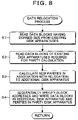
- FIG. 8 is a flowchart of a data relocation process of FIGS. 5A and 5B requiring a read from the existing disk apparatus for parity calculation;
- FIGS. 9A and 9B are illustrative diagrams of a process of increasing a volume size by adding a disk apparatus when the performance is determined as having been deteriorated;
- FIGS. 10A and 10B are illustrative diagrams of a relocation process for writing a part of data blocks of the existing disk corresponding to FIGS. 9A and 9B in an additional disk apparatus;
- FIGS. 11A and 11B are illustrative diagrams showing details of the relocation process of FIGS. 10A and 10B ;
- FIG. 12 is a flowchart of a data relocation process of FIGS. 5A and 5B allowing parity calculation by reading only a relocated data block from the existing disk;
- FIGS. 13A and 13B are illustrative diagrams of a data relocation process corresponding to FIG. 12 ;
- FIGS. 14A and 14B are illustrative diagrams showing details of the relocation process of FIGS. 13A and 13B .
- FIG. 1 is a block diagram of a disk array apparatus that functions as a storage control apparatus according to the present invention.
- a disk array apparatus 10 is connected via a network 14 to servers 12 - 1 and 12 - 2 .
- the disk array apparatus 10 according to the present invention is used as a storage in a storage area network (SAN).
- SAN storage area network
- the servers 12 - 1 and 12 - 2 and the disk array apparatus 10 serving as a storage are connected to each other via a dedicated network 14 , such as a fiber channel.
- the disk array apparatus 10 according to the present invention can be used as a network attached storage (NAS).
- NAS network attached storage
- the servers 12 - 1 and 12 - 2 function as file servers sharing the disk array apparatus 10 via the network 14 .
- the disk array apparatus 10 supports file access protocols by different OSes (Operation Systems) in the servers 12 - 1 and 12 - 2 , thereby allowing files to be shared among different OSes.
- OSes Operating Systems
- the OS of the server 12 - 1 is UNIX (R)
- the OS of the server 12 - 2 is WINDOWS (R).
- the disk array apparatus 10 is provided with a channel adaptor 16 , control modules 18 - 1 and 18 - 2 , and disk arrays 20 - 1 and 20 - 2 .
- the channel adaptor 16 executes, via the network 14 , a network process required for file access between the servers 12 - 1 and 12 - 2 .
- the control modules 18 - 1 and 18 - 2 are each provided with, as typically shown by the control module 18 - 1 , a CPU 22 .
- a communication adaptor 26 To a bus 24 of the CPU 22 , a communication adaptor 26 , a cache memory 28 , and device interfaces 30 - 1 and 30 - 2 are connected.
- the CPU 22 executes a file input/output process on a volume formed of the disk arrays 20 - 1 and 20 - 2 .
- the cache memory 28 operates as a write cache or read cache for the disk arrays 20 - 1 and 20 - 2 .
- the communication adaptor 26 processes communication with the redundant control module 18 - 2 .
- the device interfaces 30 - 1 and 30 - 2 are provided correspondingly to the disk arrays 20 - 1 and 20 - 2 , and are implemented by using, for example, SCSI disk drivers supporting a SCSI interface.
- the disk arrays 20 - 1 and 20 - 2 are each provided with disk apparatuses 36 - 1 to 36 - 4 , as typically shown by the disk array 20 - 1 .
- three disk apparatuses 36 - 1 to 36 - 3 form a volume having a RAID configuration while the disk array apparatus 10 is initially being operated in association with start-up.
- RAID 4 being taken as an exemplary RAID configuration
- the disk apparatuses 36 - 1 and 36 - 2 are for data
- the disk apparatus 36 - 3 is for parity.
- the disk apparatus 36 - 4 is an additional disk apparatus for expanding the volume size when the performance is determined through performance measurement according to the present invention as having been deteriorated.
- the number of disk apparatuses having a RAID configuration in the disk array 20 - 1 can be assumed to be arbitrary as required.
- disk apparatuses can be contained in advance, a required number of which can be added as required to increase the volume size.
- An example of the disk array apparatus 10 to which the present invention is applied includes ETERNUS NR1000F series manufactured by Fujitsu Limited.
- FIGS. 2A and 2B are block diagrams of a functional structure of the disk array apparatus 10 of FIG. 1 to which the present invention is applied.
- the disk array apparatus 10 according to the present invention connected via the network 14 to the servers 12 - 1 and 12 - 2 is provided with, in addition to the channel adaptor 16 , a resource processing unit 40 , a cache processing unit 42 , a RAID control unit 44 , and a device interface 30 , which achieve a function of the control module 18 - 1 .
- the channel adaptor 16 executes a network process on the servers 12 - 1 and 12 - 2 .
- the resource processing unit 40 , the cache processing unit 42 , the RAID control unit 44 , and the device interface 30 forming the control module 18 - 1 execute a file process on the volume 38 having a RAID configuration formed of the disk apparatuses for data 36 - 1 and 36 - 2 and the disk apparatus for parity 36 - 3 .
- the volume 38 having a configuration of RAID level 4together with the disk apparatuses for data 36 - 1 and 36 - 2 and the disk apparatus for parity 36 - 3 for the volume 38 is taken as an example. Therefore, the RAID control unit 44 executes an input/output process on the RAID level 4 of the volume 38 by taking a data block as a basic unit.
- data blocks transferred with the write request are assigned to a write logic block address of the disk apparatuses for data 36 - 1 and 36 - 2 .
- parity is calculated through an XOR from two pieces of block data assigned to the same logic block address to generate a parity block for the parity data apparatus 36 - 3 , and then the same logic block address is specified for the disk apparatuses for data 36 - 1 and 36 - 2 and the disk apparatus for parity 36 - 3 to concurrently write the data blocks and the parity.
- the cache processing unit 42 normally performs a cache write on a cache memory to respond a write end to the server side, and then performs a write-back of cache block data deleted through LRU (Least Recently Used) management or the like to the volume 38 side.
- LRU Least Recently Used
- the cache processing unit 42 when a cache hit does not occurs with the cache processing unit 42 , from the volume 38 side via the RAID control unit 44 and the device interface 30 , a logic block address and its corresponding data block through specification by the disk apparatus are read, and then a response is then made to the server.
- the RAID control unit 44 is provided with a performance measuring unit 46 , a performance-measurement-value storage unit 48 , a performance-measurement-value table 50 , a performance threshold table 52 , and a performance improving unit 54 .
- the performance measuring unit 46 periodically measures the performance of the disk apparatuses for data 36 - 1 and 36 - 2 and the disk apparatus for parity 36 - 3 forming the volume 38 while the disk array apparatus 10 is in operation.
- the performance-measurement-value storage unit 48 stores a performance measurement value measured by the performance measuring unit 46 in the performance-measurement-value table 50 . Items of performance measurement values obtained through measurement of the disk apparatus in the present invention include the following.
- a read/write performance represented by a data transfer amount (MB/s) per unit time.
- the performance improving unit 54 increases the volume size by adding the disk apparatus 36 - 4 to the volume 38 , thereby improving the performance.
- the volume 38 of RAID level 4 being formed of three disk apparatuses, that is, the disk apparatuses for data 36 - 1 and 36 - 2 and the disk apparatus for parity 36 - 3 , if the performance of any disk apparatus is determined as having been deteriorated, the disk apparatus 36 - 4 is added to expand the size of the volume 38 , thereby increasing the number of disk apparatuses for data from two to three.
- accesses are distributed to three apparatuses instead of two, thereby improving the input/output performance of the entire volume 38 .
- the number of disk apparatuses to be added at the time of deterioration in performance is one.
- the number of apparatuses to be added can be an arbitrary number n as required. For example, one or more disk apparatuses are added so that the number of disk apparatuses for data before deterioration in performance is doubled.
- FIG. 3 is an illustrative diagram of performance-measurement-value tables provided in FIGS. 2A and 2B .
- FIG. 3 shows the state in which, in this example, three performance-measurement-value tables 50 - 1 , 50 - 2 , and 50 - 3 are stored, and the number of tables stored can be up to a maximum number corresponding to the size of a file. If the number exceeds the maximum number, the oldest table is discarded, and a new measurement table is written.
- the performance-measurement-value tables each have stored therein performance measurement values for each of the disk apparatuses 36 - 1 to 36 - 3 .
- the performance measurement values have six items, that is, a read/write performance 56 , a response time 58 , a seek time 60 , a rotation latency time 62 , the number of times of error 64 , and a free space 66 .
- a read/write performance 56 a response time 58 , a seek time 60 , a rotation latency time 62 , the number of times of error 64 , and a free space 66 .
- FIGS. 4A and 4B are illustrative diagrams of the performance threshold table 52 of FIGS. 2A and 2B .
- the performance threshold table 52 has contained therein a minimum-performance-threshold table 52 - 1 shown in FIG. 4A and a relative-performance-threshold table 52 - 2 shown in FIG. 4B .
- the minimum-performance-threshold table 52 - 1 of FIG. 4A has contained therein a minimum-performance-threshold table 52 - 1 shown in FIG. 4A and a relative-performance-threshold table 52 - 2 shown in FIG. 4B .
- minimum performance thresholds TH[A 1 ], TH[B 1 ], TH[C 1 ], TH[D 1 ], TH[E 1 ], and TH[F 1 ] are set, respectively, as fixed values.
- relative performance thresholds TH[A 2 ], TH[B 2 ], TH[C 2 ], TH[D 2 ], TH[E 2 ], and TH[F 2 ] are calculated, respectively, when it is determined from the performance measurement values whether the performance has been deteriorated, and are then stored.
- the relative performance thresholds the relative performance values are calculated by the following equation based on the measurement values on the performance-measurement-value table 50 - 1 , for example, obtained through measurement shown in FIG. 3 .
- (relative performance threshold) [(a total of performance measurement values/the number of disks)] ⁇ relative efficiency N
- a value equal to the rate of each minimum performance threshold in the minimum-performance-threshold table 52 - 1 of FIG. 4A defined by the rated performance of the disk apparatus can be used.
- the relative performance threshold has a feature in which an average value of performance measurement values in each of the disk apparatuses 36 - 1 to 36 - 3 at the moment of each periodical measurement is found, and then the performance-measurement average value is multiplied by a predetermined relative performance rate N to find a relative performance threshold, thereby determining whether the performance is relatively deteriorated with respect to an average performance of the plurality of disk apparatuses forming the volume.
- the performance improving unit 54 can select either one of determining based on the minimum-performance-threshold table 52 - 1 of FIG. 4A whether the performance has been deteriorated and determining based on the relative-performance-threshold table 52 - 2 of FIG. 4B whether the performance has been deteriorated. Also, as required, both of the minimum-performance-threshold table 52 - 1 and the relative-performance-threshold table 52 - 2 can be used to determine whether the performance has been deteriorated.
- FIGS. 5A and 5B are flowcharts of a storage control process to be performed by the disk array apparatus according to the present invention in FIGS. 2A and 2B .
- step S 2 After an initialization process is performed in step S 1 in association with power-on, it is checked in step S 2 whether a server's input/output request is present.
- step S 2 Upon determination in step S 2 as to whether a server's input/output request, an input/output process according to RAID 4 is performed on the volume 38 in step S 3 . Then, it is checked in step S 4 whether a performance-value measuring timing has come.
- the performance-value measuring timing is set at predetermined constant time intervals.
- step S 4 Upon determination in step S 4 as to the performance-value measuring timing, the procedure goes to step S 5 , wherein it is checked whether a server's input/output request is present. If a server's input/output request is present, as with the case of FIGS. 2A and 2B , an input/output process is performed in step S 6 on the volume 38 according to the RAID level 4 . Then, in step S 7 , in association with the input/output process in step S 6 , the performance measuring unit 46 performs measurement on each disk apparatus for the respective measurement items of the read/write performance, the response time, the seek time, the rotation latency time, the number of times of errors, and the free spaces.
- the performance-measurement-value storage unit 48 then stores the measurement results in the performance-measurement-value table 50 as shown in FIG. 3 .
- the performance improving unit 54 performs a performance determination process by comparing the performance measurement value stored in the performance-measurement-value table 50 and the performance threshold set in the performance threshold table 52 .
- this performance determination process either one of the minimum-performance-threshold table 52 - 1 of FIG. 4A and the relative-performance-threshold table 52 - 2 of FIG. 4B is used.
- step S 9 it is checked in step S 9 , from the results of the performance determination process, whether the performance of any one of the disk apparatuses has been deteriorated.
- step S 10 it is checked in step S 10 whether adding a disk apparatus is possible. If adding a disk apparatus is possible, a present number of n disk apparatuses, which is one in the present embodiment, is added in step S 11 to increase the size of the volume 38 . Then in step S 12 , the data in the existing disk apparatus is relocated to the additional disk apparatus, thereby preventing accesses from being concentrated on the additional disk apparatus. On the other hand, if a process of adding a disk apparatus has already been completed and addition is not possible in step S 10 , an error report is issued in step S 13 indicating that the performance is determined as having been deteriorated.
- FIG. 6 is a flowchart showing details of the performance determination process in step S 8 of FIGS. 5A and 5B using the minimum performance threshold value set on the minimum-performance-threshold table 52 - 1 of FIG. 4A .
- the performance measurement value of a specific disk apparatus is read in step S 1 . For example, from the latest performance-measurement-value table 50 - 1 in FIG.
- a measurement result A 1 of the read/write performance 56 which is the first performance measurement value, is read for the disk apparatus 36 - 1 .
- step S 2 from the minimum-performance-threshold table 52 - 1 of FIG. 4 A, the minimum performance threshold TH[A 1 ] of the read/write performance is read.
- step S 3 the read/write performance A 1 and the minimum performance threshold TH[A 1 ] are compared. If the read/write performance A 1 is smaller than the minimum performance threshold TH[A 1 ], the performance is determined as having been deteriorated, a performance deterioration flag is turned on in step S 7 , and then the procedure returns to the main routine of FIGS. 5A and 5B .
- step S 5 it is checked whether determination has been made for all disk apparatuses, and if such determination has not been made, the procedure returns to step S 1 and a similar process is repeated for the next disk apparatus 36 - 2 . If it is determined in step S 5 that determination has been made for all disk apparatuses, the procedure goes to step S 6 , wherein it is checked whether determination has been made for all measurement items, and if such determination has not been made, the procedure returns to step S 1 and a similar process is repeated for the next performance measurement value, that is, the response time.
- the measurement value of each of the read/write performance, the response time, the seek time, the rotation latency time, the number of times of error, and the free space is compared with the relevant minimum performance threshold.
- the performance deterioration flag is turned on, and the procedure returns to the main routine of FIGS. 5A and 5B , wherein deterioration in performance is recognized in step S 9 and, on condition in step S 10 that adding a disk is possible, a disk apparatus is added in step S 11 , thereby increasing the volume size.
- FIG. 7 is a flowchart showing details of the performance determination process in step S 8 of FIGS. 5A and 5B using the relative performance threshold value.
- a relative threshold for each item is calculated from the performance measurement values for all disk apparatuses. For example, when the latest performance-measurement-value table 50 - 1 shown in FIG.
- the response time 58 the seek time 60 , the rotation latency time 62 , the number of times of error 64 , and the free space 66 , relative thresholds TH[B 2 ], TH[C 2 ], TH[D 2 ], TH[E 2 ], and TH[F 2 ] are calculated.
- step S 2 the performance measurement value of the disk apparatus is read. For example, from the latest performance-measurement-value table 50 in FIG. 3 , the measurement value A 1 of the read/write performance 56 of the disk apparatus 36 - 1 is read. Then in step S 3 , the relative performance threshold calculated in step S 1 is compared with the measurement performance value read in step S 2 . If the performance measurement value is equal to or smaller than the measurement performance threshold, the performance is determined in step S 4 as having been deteriorated, the performance deterioration flag is turned on in step S 7 , and the procedure returns to the main routine of FIGS. 5A and 5B .
- step S 5 If the performance measurement value is larger than the relative performance threshold, it is determined in step S 5 whether determination has been made for all disk apparatuses, and then a similar process can be repeated in step S 2 for the next disk apparatus. If it is determined in step S 5 that determination has been made for all disk apparatuses, it is checked in step S 6 whether determination has been made for all measurement items, and then the procedure can be returned to step S 2 for repeating a similar process for the next measurement item.
- the performance measurement values in the latest performance-measurement-value table 50 of FIG. 3 are each compared with the calculated relative thresholds in the relative-performance-threshold table 52 - 2 of FIG. 4B for determination. If the performance is determined as being deteriorated for any one of the items, a disk is added to the volume to increase the volume size, thereby improving the performance.
- FIG. 8 is a flowchart of a data relocation process in step S 12 of FIGS. 5A and 5B after a disk apparatus is added.
- the case where a read from the existing disk apparatus is required for parity calculation is taken as an example.
- data blocks having the size corresponding to the latest stored file are read in step S 1 from the existing disk apparatuses.
- step S 2 data blocks in the existing disk apparatuses required for parity calculation are read.
- step S 3 new parities are calculated in association with relocation for the additional disk apparatus.
- step S 4 block addresses of the additional disk apparatus are sequentially specified to write the data blocks in the additional disk apparatus and, at the same time, the parities are written in the disk apparatus for parity.
- FIGS. 9A and 9B are illustrative diagrams of a process of increasing a volume size by adding a disk apparatus when the performance is determined as having been deteriorated.
- FIG. 9A shows the volume 38 before addition, wherein the disk apparatuses for data 36 - 1 and 36 - 2 and the disk apparatus for parity 36 - 3 form the volume 38 at the RAID level 4.
- data blocks A 1 , B 1 , C 1 , and D 1 are stored in the data disk 36 - 1
- data blocks A 2 , B 2 , C 2 , and D 2 are stored in the disk apparatuses for data 36 - 2
- parities P 1 , P 2 , P 3 , and P 4 calculated through an XOR of both of the above are stored in the disk apparatus for parity 36 - 3 .
- the disk apparatus 36 - 4 is added as shown in FIG. 9B to expand the size of the volume 38 .
- FIGS. 10A and 10B the data relocation process according to the flowchart of FIG. 8 is performed.
- FIG. 10A from the existing disk apparatuses for data 36 - 1 and 36 - 2 , the data blocks A 1 , B 1 , C 1 and D 1 and the data blocks A 2 , B 2 , C 2 and D 2 forming a file 70 read on memory of the control module 18 .
- These data blocks read as the file 70 are written in the additional disk apparatus 36 - 4 in a free state in its entirety, as shown in FIG. 10B .
- parities P 1 ′ to P 8 ′ newly calculated in association with the write of the data blocks in the additional disk apparatus 36 - 4 are written.
- FIGS. 11A and 11B are illustrative diagrams showing details of the relocation process of FIGS. 10A and 10B , wherein data blocks are arranged in order of block address for each disk apparatus.
- FIG. 11A shows a storage state of the data blocks in the disk apparatuses 36 - 1 to 36 - 4 before data relocation. In this storage state, data relocation is performed such that, for example, read areas 72 - 1 and 72 - 2 each having four blocks from the head of the existing disk apparatuses 36 - 1 and 36 - 2 forming the file 70 are first read, and then data is relocated to relocation areas 74 - 1 and 74 - 2 of the additional disk apparatus 36 - 4 shown in FIG. 11B .
- parities P 1 ′ to P 8 ′ newly calculated in association with data relocation are stored.
- the parities P 1 ′ to P 4 ′ can be calculated only from the data blocks A 1 to D 1 of the read area 72 - 1 .
- the parity update area 76 - 2 an XOR of the data blocks A 2 , B 2 , C 2 , and D 2 of the data relocation area 74 - 2 and data blocks of the read areas 78 - 1 and 78 - 2 each having another four blocks of the existing disk apparatuses 36 - 1 and 36 - 2 is required.
- the read areas 78 - 1 and 78 - 2 of the existing disk apparatuses 36 - 1 and 36 - 2 are read, and then the parities P 5 ′ to P 8 ′ are calculated for updating between the relocation areas 74 - 1 and 74 - 2 from an XOR for each data block group of the same block address.
- FIG. 12 is a flowchart showing a data relocation process on the additional disk apparatus in step S 12 of FIGS. 5A and 5B according to another embodiment.
- this data relocation process only the relocation data blocks read from the existing disk apparatuses are required for parity calculation.
- data blocks having a defined size are read in step S 1 from the existing disk apparatuses.
- step S 2 new parities in association with data relocation to the additional disk apparatus are calculated.
- step S 3 free block addresses are sequentially specified, and the data blocks are written in all of the disk apparatuses for data including the existing disk apparatuses and the additional disk apparatus and, at the same time, the parities are written in the disk apparatus for parity.
- FIGS. 13A and 13B are illustrative diagrams of a data relocation process corresponding to the flowchart of FIG. 12 .
- FIG. 13A shows a read process from the existing disk apparatus for data relocation when the disk apparatus 36 - 4 is added.
- the data blocks A 1 , B 1 , C 1 , and D 1 and the data blocks A 2 , B 2 , C 2 , and D 2 forming the file 70 are read from the existing disk apparatuses 36 - 1 and 36 - 2 .
- the data blocks forming the file 70 are written equally in free areas of the existing disk apparatuses 36 - 1 and 36 - 2 and the additional disk apparatus 36 - 4 .
- the file 70 is formed of eight data blocks, three blocks from the head are sequentially written in each of the existing disk apparatuses 36 - 1 and 36 - 2 , and then the remaining two are written in the additional disk apparatus 36 - 4 .
- parities P′ 1 , P′ 2 , and P′ 3 have been calculated and stored based on the data forming the file 70 read from the existing disk apparatuses 36 - 1 and 36 - 2 . Therefore, unlike the data relocation of FIGS. 10A and 10B , other data blocks do not have to be newly read from the existing disk apparatuses 36 - 1 and 36 - 2 for parity calculation.
- FIGS. 14A and 14B are illustrative diagrams showing details of the relocation process of FIGS. 13A and 13B .
- FIG. 14A shows the state before data relocation, wherein, for example, read areas 72 - 1 and 72 - 2 forming the file 70 and each having four blocks from the head are read from the existing disk apparatuses 36 - 1 and 36 - 2 . Then, as shown in FIG.
- the read eight data blocks A 1 to D 1 and A 2 to D 2 are equally divided from the head into data blocks A 1 to C 1 , data blocks A 2 to C 2 , and data blocks D 1 and D 2 , and with free areas of the existing disk apparatuses 36 - 1 and 36 - 2 and the additional disk apparatus 36 - 4 being taken as relocation areas 82 - 1 , 82 - 2 , and 82 - 4 , then block addresses are read and sequentially read.
- a relocation area 82 - 3 of the disk apparatus for parity 36 - 3 parities P 1 ′, P 2 ′ and P 3 ′ are calculated and stored.
- the parities P 1 ′, P 2 ′ and P 3 ′ are calculated such that, in accordance with the allocation of the data blocks in the relocation areas 82 - 1 , 82 - 2 , and 82 - 4 in the disk apparatuses 36 - 1 , 36 - 2 , and 36 - 4 of FIG. 14B , an XOR calculation is performed for each of data blocks located at the same block address, that is, for each of (A 1 , A 2 , D 1 ), (B 1 , B 2 , D 2 ) and (C 1 , C 2 ), and then are stored. In such data relocation of FIGS.
- parity calculation at the time of data relocation can be performed only from the data blocks subjected to data relocation, and data blocks for parity calculation do not have to be newly read from the existing disk apparatuses, thereby reducing processing load.
- the present invention is to provide a program executed by the CPU 22 in the control module 18 - 1 provided in the disk array apparatus 10 of FIG. 1 .
- This program includes procedures according to the flowcharts of FIGS. 5A , 5 B, 6 , 7 , 8 , and 12 .
- the case of a volume formed of RAID level 4 is taken as an example.
- the present invention can also be applied to a volume formed of another RAID level by increasing the disk size so that the volume size is increased when the performance of a specific disk apparatus is determined as having been deteriorated.
- the measurement result on the latest performance-measurement-value table and the performance threshold are compared to determine whether the performance has been deteriorated.
- an average value of performance measurement values may be each calculated from a plurality of performance measurement tables including the latest performance measurement table to determine, by comparison with the performance threshold, whether the performance has been deteriorated. The same goes for calculation of the relative performance threshold on the relative-performance-threshold table 52 - 2 of FIG.
Abstract
Description
- [Patent Document 1] Japanese Patent Laid-Open Publication No. 2000-039970
- [Patent Document 2] Japanese Patent Laid-Open Publication No. 2000-293320
(relative performance threshold)=[(a total of performance measurement values/the number of disks)]×relative efficiency N
Here, the relative efficiency N takes an arbitrary value in the range of N=0% to 100%. Specifically, a value equal to the rate of each minimum performance threshold in the minimum-performance-threshold table 52-1 of
TH[A2]=[(A1+A2+A3)/3]×N.
Similarly, as for the
Claims (20)
Applications Claiming Priority (2)
| Application Number | Priority Date | Filing Date | Title |
|---|---|---|---|
| JP2005140780A JP4473175B2 (en) | 2005-05-13 | 2005-05-13 | Storage control method, program, and apparatus |
| JP2005-140780 | 2005-05-13 |
Publications (2)
| Publication Number | Publication Date |
|---|---|
| US20060259686A1 US20060259686A1 (en) | 2006-11-16 |
| US7502905B2 true US7502905B2 (en) | 2009-03-10 |
Family
ID=37420524
Family Applications (1)
| Application Number | Title | Priority Date | Filing Date |
|---|---|---|---|
| US11/214,838 Expired - Fee Related US7502905B2 (en) | 2005-05-13 | 2005-08-31 | Storage control method, program and apparatus for accessing disk array |
Country Status (2)
| Country | Link |
|---|---|
| US (1) | US7502905B2 (en) |
| JP (1) | JP4473175B2 (en) |
Cited By (2)
| Publication number | Priority date | Publication date | Assignee | Title |
|---|---|---|---|---|
| US20110231362A1 (en) * | 2010-03-16 | 2011-09-22 | Deepak Attarde | Extensible data deduplication system and method |
| US20120131586A1 (en) * | 2010-11-18 | 2012-05-24 | Electronics And Telecommunications Research Institute | Apparatus and method for controlling response time of application program |
Families Citing this family (50)
| Publication number | Priority date | Publication date | Assignee | Title |
|---|---|---|---|---|
| JP4949791B2 (en) * | 2006-09-29 | 2012-06-13 | 株式会社日立製作所 | Volume selection method and information processing system |
| US7913051B1 (en) * | 2006-12-22 | 2011-03-22 | Emc Corporation | Methods and apparatus for increasing the storage capacity of a zone of a storage system |
| US8046561B1 (en) * | 2006-12-22 | 2011-10-25 | Emc Corporation | Methods and apparatus for selecting a storage zone for a content unit |
| US8312214B1 (en) | 2007-03-28 | 2012-11-13 | Netapp, Inc. | System and method for pausing disk drives in an aggregate |
| US8006050B2 (en) | 2007-04-19 | 2011-08-23 | International Business Machines Corporation | System for determining allocation of tape drive resources for a secure data erase process |
| JP5203788B2 (en) * | 2007-04-19 | 2013-06-05 | インターナショナル・ビジネス・マシーンズ・コーポレーション | Method, computer program and system for determining tape drive allocation for secure data erasure process |
| JP4853375B2 (en) * | 2007-04-27 | 2012-01-11 | 富士ゼロックス株式会社 | Status detection device, status detection method, and status detection program |
| JP5013099B2 (en) * | 2007-12-14 | 2012-08-29 | 日本電気株式会社 | Disk bandwidth calculation system, method, and program |
| US7984259B1 (en) * | 2007-12-17 | 2011-07-19 | Netapp, Inc. | Reducing load imbalance in a storage system |
| JP5216463B2 (en) * | 2008-07-30 | 2013-06-19 | 株式会社日立製作所 | Storage device, storage area management method thereof, and flash memory package |
| JP2010049613A (en) * | 2008-08-25 | 2010-03-04 | Nec Corp | Storage device, and method and program for managing storage performance |
| JP5223602B2 (en) * | 2008-11-04 | 2013-06-26 | 日本電気株式会社 | Storage system, performance determination method thereof, disk array control unit |
| US8874867B2 (en) * | 2008-11-21 | 2014-10-28 | Lsi Corporation | Identification and containment of performance hot-spots in virtual volumes |
| US8291131B2 (en) | 2009-07-06 | 2012-10-16 | Micron Technology, Inc. | Data transfer management |
| JP5504936B2 (en) * | 2010-02-03 | 2014-05-28 | 富士通株式会社 | Storage apparatus and data storage control method |
| JP6255687B2 (en) * | 2013-03-26 | 2018-01-10 | 日本電気株式会社 | RAID construction device, RAID construction method, and RAID construction program |
| KR101694978B1 (en) * | 2013-04-29 | 2017-01-11 | 한국전자통신연구원 | Network option apparatus and the operating method |
| GB2517195A (en) * | 2013-08-15 | 2015-02-18 | Ibm | Computer system productivity monitoring |
| US9857974B2 (en) * | 2013-10-03 | 2018-01-02 | International Business Machines Corporation | Session execution decision |
| US11836369B1 (en) * | 2015-02-27 | 2023-12-05 | Pure Storage, Inc. | Storing data in an expanded storage pool of a vast storage network |
| US10437486B2 (en) | 2016-05-24 | 2019-10-08 | Samsung Electronics Co., Ltd. | Method and apparatus for tenant-aware storage sharing platform |
| US11194517B2 (en) * | 2016-05-24 | 2021-12-07 | Samsung Electronics Co., Ltd. | Method and apparatus for storage device latency/bandwidth self monitoring |
| US10474374B2 (en) * | 2016-05-24 | 2019-11-12 | Samsung Electronics Co., Ltd. | Method and apparatus for storage device latency/bandwidth self monitoring |
| US10439881B2 (en) | 2016-05-24 | 2019-10-08 | Samsung Electronics Co., Ltd. | Method and apparatus for predicting storage distance |
| JP6946716B2 (en) | 2017-04-28 | 2021-10-06 | 富士通株式会社 | Storage controller, storage control program and storage control method |
| US11947489B2 (en) | 2017-09-05 | 2024-04-02 | Robin Systems, Inc. | Creating snapshots of a storage volume in a distributed storage system |
| US11748203B2 (en) | 2018-01-11 | 2023-09-05 | Robin Systems, Inc. | Multi-role application orchestration in a distributed storage system |
| US11582168B2 (en) | 2018-01-11 | 2023-02-14 | Robin Systems, Inc. | Fenced clone applications |
| US11099937B2 (en) | 2018-01-11 | 2021-08-24 | Robin Systems, Inc. | Implementing clone snapshots in a distributed storage system |
| US11392363B2 (en) | 2018-01-11 | 2022-07-19 | Robin Systems, Inc. | Implementing application entrypoints with containers of a bundled application |
| US11023328B2 (en) | 2018-07-30 | 2021-06-01 | Robin Systems, Inc. | Redo log for append only storage scheme |
| US10976938B2 (en) | 2018-07-30 | 2021-04-13 | Robin Systems, Inc. | Block map cache |
| US10908848B2 (en) * | 2018-10-22 | 2021-02-02 | Robin Systems, Inc. | Automated management of bundled applications |
| US11036439B2 (en) | 2018-10-22 | 2021-06-15 | Robin Systems, Inc. | Automated management of bundled applications |
| US11086725B2 (en) | 2019-03-25 | 2021-08-10 | Robin Systems, Inc. | Orchestration of heterogeneous multi-role applications |
| US11256434B2 (en) | 2019-04-17 | 2022-02-22 | Robin Systems, Inc. | Data de-duplication |
| US11226847B2 (en) | 2019-08-29 | 2022-01-18 | Robin Systems, Inc. | Implementing an application manifest in a node-specific manner using an intent-based orchestrator |
| US11520650B2 (en) | 2019-09-05 | 2022-12-06 | Robin Systems, Inc. | Performing root cause analysis in a multi-role application |
| US11249851B2 (en) | 2019-09-05 | 2022-02-15 | Robin Systems, Inc. | Creating snapshots of a storage volume in a distributed storage system |
| US11113158B2 (en) | 2019-10-04 | 2021-09-07 | Robin Systems, Inc. | Rolling back kubernetes applications |
| US11347684B2 (en) | 2019-10-04 | 2022-05-31 | Robin Systems, Inc. | Rolling back KUBERNETES applications including custom resources |
| US11403188B2 (en) | 2019-12-04 | 2022-08-02 | Robin Systems, Inc. | Operation-level consistency points and rollback |
| US11108638B1 (en) * | 2020-06-08 | 2021-08-31 | Robin Systems, Inc. | Health monitoring of automatically deployed and managed network pipelines |
| US11528186B2 (en) | 2020-06-16 | 2022-12-13 | Robin Systems, Inc. | Automated initialization of bare metal servers |
| US11740980B2 (en) | 2020-09-22 | 2023-08-29 | Robin Systems, Inc. | Managing snapshot metadata following backup |
| US11743188B2 (en) | 2020-10-01 | 2023-08-29 | Robin Systems, Inc. | Check-in monitoring for workflows |
| US11271895B1 (en) | 2020-10-07 | 2022-03-08 | Robin Systems, Inc. | Implementing advanced networking capabilities using helm charts |
| US11456914B2 (en) | 2020-10-07 | 2022-09-27 | Robin Systems, Inc. | Implementing affinity and anti-affinity with KUBERNETES |
| US11750451B2 (en) | 2020-11-04 | 2023-09-05 | Robin Systems, Inc. | Batch manager for complex workflows |
| US11556361B2 (en) | 2020-12-09 | 2023-01-17 | Robin Systems, Inc. | Monitoring and managing of complex multi-role applications |
Citations (9)
| Publication number | Priority date | Publication date | Assignee | Title |
|---|---|---|---|---|
| JP2000039970A (en) | 1998-07-24 | 2000-02-08 | Nec Software Kobe Ltd | System for controlling double failure prevention of disk array system |
| US6058489A (en) * | 1995-10-13 | 2000-05-02 | Compaq Computer Corporation | On-line disk array reconfiguration |
| JP2000293320A (en) * | 1999-04-06 | 2000-10-20 | Toshiba Corp | Disk subsystem, inspection diagnosing method for disk subsystem and data restoring method for disk subsystem |
| US6275898B1 (en) * | 1999-05-13 | 2001-08-14 | Lsi Logic Corporation | Methods and structure for RAID level migration within a logical unit |
| US20030120864A1 (en) * | 2001-12-26 | 2003-06-26 | Lee Edward K. | High-performance log-structured RAID |
| US20030157896A1 (en) * | 2000-05-12 | 2003-08-21 | Jerome Mee | Controlling performance measurements in a telecommunications network |
| US7111147B1 (en) * | 2003-03-21 | 2006-09-19 | Network Appliance, Inc. | Location-independent RAID group virtual block management |
| US7185144B2 (en) * | 2003-11-24 | 2007-02-27 | Network Appliance, Inc. | Semi-static distribution technique |
| US20070055820A1 (en) * | 2004-02-26 | 2007-03-08 | Hitachi, Ltd. | Storage subsystem and performance tuning method |
-
2005
- 2005-05-13 JP JP2005140780A patent/JP4473175B2/en not_active Expired - Fee Related
- 2005-08-31 US US11/214,838 patent/US7502905B2/en not_active Expired - Fee Related
Patent Citations (9)
| Publication number | Priority date | Publication date | Assignee | Title |
|---|---|---|---|---|
| US6058489A (en) * | 1995-10-13 | 2000-05-02 | Compaq Computer Corporation | On-line disk array reconfiguration |
| JP2000039970A (en) | 1998-07-24 | 2000-02-08 | Nec Software Kobe Ltd | System for controlling double failure prevention of disk array system |
| JP2000293320A (en) * | 1999-04-06 | 2000-10-20 | Toshiba Corp | Disk subsystem, inspection diagnosing method for disk subsystem and data restoring method for disk subsystem |
| US6275898B1 (en) * | 1999-05-13 | 2001-08-14 | Lsi Logic Corporation | Methods and structure for RAID level migration within a logical unit |
| US20030157896A1 (en) * | 2000-05-12 | 2003-08-21 | Jerome Mee | Controlling performance measurements in a telecommunications network |
| US20030120864A1 (en) * | 2001-12-26 | 2003-06-26 | Lee Edward K. | High-performance log-structured RAID |
| US7111147B1 (en) * | 2003-03-21 | 2006-09-19 | Network Appliance, Inc. | Location-independent RAID group virtual block management |
| US7185144B2 (en) * | 2003-11-24 | 2007-02-27 | Network Appliance, Inc. | Semi-static distribution technique |
| US20070055820A1 (en) * | 2004-02-26 | 2007-03-08 | Hitachi, Ltd. | Storage subsystem and performance tuning method |
Cited By (3)
| Publication number | Priority date | Publication date | Assignee | Title |
|---|---|---|---|---|
| US20110231362A1 (en) * | 2010-03-16 | 2011-09-22 | Deepak Attarde | Extensible data deduplication system and method |
| US8732133B2 (en) * | 2010-03-16 | 2014-05-20 | Commvault Systems, Inc. | Extensible data deduplication system and method |
| US20120131586A1 (en) * | 2010-11-18 | 2012-05-24 | Electronics And Telecommunications Research Institute | Apparatus and method for controlling response time of application program |
Also Published As
| Publication number | Publication date |
|---|---|
| JP4473175B2 (en) | 2010-06-02 |
| JP2006318246A (en) | 2006-11-24 |
| US20060259686A1 (en) | 2006-11-16 |
Similar Documents
| Publication | Publication Date | Title |
|---|---|---|
| US7502905B2 (en) | Storage control method, program and apparatus for accessing disk array | |
| US8156381B2 (en) | Storage management apparatus and storage system | |
| US9081690B2 (en) | Storage system and management method of control information therein | |
| US6185639B1 (en) | System and method to reduce a computer system's interrupt processing overhead | |
| US7421535B2 (en) | Method for demoting tracks from cache | |
| US10346245B2 (en) | Data storage system and data storage method | |
| US8738963B2 (en) | Methods and apparatus for managing error codes for storage systems coupled with external storage systems | |
| US8046548B1 (en) | Maintaining data consistency in mirrored cluster storage systems using bitmap write-intent logging | |
| US7260679B2 (en) | Apparatus and method to manage a data cache using a first and second least recently used list | |
| US9015434B2 (en) | Storage system, and apparatus and method for controlling storage | |
| US20100023847A1 (en) | Storage Subsystem and Method for Verifying Data Using the Same | |
| US8010490B2 (en) | Apparatus for managing remote copying between storage systems | |
| US20040019821A1 (en) | Method and apparatus for reliable failover involving incomplete raid disk writes in a clustering system | |
| US8140811B2 (en) | Nonvolatile storage thresholding | |
| US8060707B2 (en) | Minimization of read response time | |
| JP5938965B2 (en) | Node device and processing speed management method of multi-node storage system | |
| CN112181298B (en) | Array access method, array access device, storage equipment and machine-readable storage medium | |
| US20120047511A1 (en) | Throttling storage initialization for data destage | |
| US9298397B2 (en) | Nonvolatile storage thresholding for ultra-SSD, SSD, and HDD drive intermix | |
| US20070277018A1 (en) | Storage area allocating apparatus, storage area allocating method, and computer product | |
| US20130019122A1 (en) | Storage device and alternative storage medium selection method | |
| US20140173337A1 (en) | Storage apparatus, control method, and control program | |
| Cisco | White Paper: Physical Storage Best Practices for Cisco Unity with Microsoft Exchange | |
| US20230342080A1 (en) | Storage management system and method | |
| JP2002116936A (en) | Disk array device |
Legal Events
| Date | Code | Title | Description |
|---|---|---|---|
| AS | Assignment |
Owner name: FUJITSU LIMITED, JAPAN Free format text: ASSIGNMENT OF ASSIGNORS INTEREST;ASSIGNOR:SONOBE, SATOSHI;REEL/FRAME:016948/0516 Effective date: 20050725 |
|
| STCF | Information on status: patent grant |
Free format text: PATENTED CASE |
|
| CC | Certificate of correction | ||
| FEPP | Fee payment procedure |
Free format text: PAYOR NUMBER ASSIGNED (ORIGINAL EVENT CODE: ASPN); ENTITY STATUS OF PATENT OWNER: LARGE ENTITY |
|
| FPAY | Fee payment |
Year of fee payment: 4 |
|
| FPAY | Fee payment |
Year of fee payment: 8 |
|
| FEPP | Fee payment procedure |
Free format text: MAINTENANCE FEE REMINDER MAILED (ORIGINAL EVENT CODE: REM.); ENTITY STATUS OF PATENT OWNER: LARGE ENTITY |
|
| LAPS | Lapse for failure to pay maintenance fees |
Free format text: PATENT EXPIRED FOR FAILURE TO PAY MAINTENANCE FEES (ORIGINAL EVENT CODE: EXP.); ENTITY STATUS OF PATENT OWNER: LARGE ENTITY |
|
| STCH | Information on status: patent discontinuation |
Free format text: PATENT EXPIRED DUE TO NONPAYMENT OF MAINTENANCE FEES UNDER 37 CFR 1.362 |
|
| FP | Lapsed due to failure to pay maintenance fee |
Effective date: 20210310 |