US7508417B2 - Wireless imaging apparatus and its control method - Google Patents
Wireless imaging apparatus and its control method Download PDFInfo
- Publication number
- US7508417B2 US7508417B2 US10/677,623 US67762303A US7508417B2 US 7508417 B2 US7508417 B2 US 7508417B2 US 67762303 A US67762303 A US 67762303A US 7508417 B2 US7508417 B2 US 7508417B2
- Authority
- US
- United States
- Prior art keywords
- imaging
- wireless communication
- devices
- lens
- wireless
- Prior art date
- Legal status (The legal status is an assumption and is not a legal conclusion. Google has not performed a legal analysis and makes no representation as to the accuracy of the status listed.)
- Expired - Fee Related, expires
Links
Images


Classifications
-
- H—ELECTRICITY
- H01—ELECTRIC ELEMENTS
- H01Q—ANTENNAS, i.e. RADIO AERIALS
- H01Q1/00—Details of, or arrangements associated with, antennas
- H01Q1/12—Supports; Mounting means
- H01Q1/22—Supports; Mounting means by structural association with other equipment or articles
-
- H—ELECTRICITY
- H04—ELECTRIC COMMUNICATION TECHNIQUE
- H04N—PICTORIAL COMMUNICATION, e.g. TELEVISION
- H04N1/00—Scanning, transmission or reproduction of documents or the like, e.g. facsimile transmission; Details thereof
- H04N1/00095—Systems or arrangements for the transmission of the picture signal
- H04N1/00103—Systems or arrangements for the transmission of the picture signal specially adapted for radio transmission, e.g. via satellites
-
- H—ELECTRICITY
- H04—ELECTRIC COMMUNICATION TECHNIQUE
- H04N—PICTORIAL COMMUNICATION, e.g. TELEVISION
- H04N23/00—Cameras or camera modules comprising electronic image sensors; Control thereof
- H04N23/50—Constructional details
- H04N23/55—Optical parts specially adapted for electronic image sensors; Mounting thereof
-
- H—ELECTRICITY
- H04—ELECTRIC COMMUNICATION TECHNIQUE
- H04N—PICTORIAL COMMUNICATION, e.g. TELEVISION
- H04N23/00—Cameras or camera modules comprising electronic image sensors; Control thereof
- H04N23/60—Control of cameras or camera modules
- H04N23/66—Remote control of cameras or camera parts, e.g. by remote control devices
- H04N23/661—Transmitting camera control signals through networks, e.g. control via the Internet
Definitions
- the present invention relates to a wireless imaging apparatus and its control method.
- a cellular phone using a magnetic wave in a 900 to 1900 MHz band is indispensable as an anytime-and-anywhere communicable wireless mobile communication tool.
- wireless communication using a radio wave in a 2.45 GHz band in conformity with wireless LAN (IEEE 802.11b or IEEE 802.11a) or Bluetooth standard is realized and widely used in offices and houses.
- a Suica (registered trademark) card adopted by East Japan Railway Company in 2001, realizes non-contact reading and writing of ticket at a station ticket gate.
- radio tags are used for personal identification (ID) purpose and the like.
- ID personal identification
- an anti-theft automobile key is realized by using a small radio tag of about 1 cm embedded in the key thereby enabling an authentication operation upon turning-on of the key.
- optical communication is employed for high-speed communication of images obtained by a camera.
- a value-added network incorporating a large number of sensors has been actively developed.
- a system as a precaution against earthquake constructed with an acceleration sensor and a strain sensor embedded into a steel frame of a building structure for measuring the degree of fatigue of the steel frame or concrete.
- Nikkei Electronics issued Jul. 15, 2002 introduces in pp 99 to 129, several sensing network systems. For example, a large number of sensors are distributed in a forest, and the amount of generated oxygen, the amount of absorbed CO 2 , the temperature, humidity of the forest and the like are grasped in detail, for the purpose of early detection of bush fire or CO 2 emission trading.
- an imaging network by optical sensing may be constructed.
- U.S. Pat. No. 5,004,328 discloses a spherical lens 1 including an aperture 2 in its central portion as shown in FIG. 11 . It is known that the aperture improves image formation characteristic of the imaging system.
- a wireless sensing network is constructed by arranging a large number of sensing devices (hereinbelow, each referred to as an “Mote”), to sense a slight environmental change in a wide range, the size of the Mote must be small. Further, in wireless communication, to perform communication with a place as far as possible, the size of antenna must be as large as possible.
- Mote sensing devices
- the size of the Mote increases, which disturbs construction of wireless sensing network for excellent sensitivity to environmental change. Further, as the structure of the Mote is complicated, a manufacturing process of the Mote becomes complicated.
- sensing Mote a sensing network system with distributed devices having sensing and communication functions
- the sensing function installed in the small sensing Mote is limited.
- the present invention has its object to solve the above-described problems individually or at once, and to simplify the structure of a wireless imaging apparatus without increasing the size of the apparatus.
- a wireless imaging device comprising: an imaging section, arranged to provide a function of imaging a subject; and a communication section, arranged to provide a wireless communication function, wherein the imaging section comprises an optical lens, an aperture to limit incident light on the optical lens, an optical sensor to convert the incident light passed through the aperture into an electric signal, and an antenna integrally provided with the aperture, to wireless-transmit the electric signal converted into a radio signal by the communication section.
- an image obtaining apparatus comprising a plurality of the above devices, wherein the plurality of devices and the wireless communication construct a network of the plural devices.
- Another object of the present invention is to simplify to functions of each wireless imaging apparatus and to provide a high-level imaging function by realizing co-operative work by plural wireless imaging apparatuses.
- an image obtaining apparatus comprising a plurality of imaging devices which provide a wireless communication function and a single imaging function, wherein the plurality of imaging devices provide, as a whole, one or more high-level imaging functions by co-operative work using the wireless communication function.
- FIGS. 1 and 2 are schematic diagrams showing a wireless imaging device included in a wireless imaging apparatus according to a first embodiment of the present invention
- FIGS. 3 to 5 are schematic diagrams showing an aperture of the wireless imaging device
- FIGS. 6 and 7 are explanatory views showing a manufacturing method of the wireless imaging device
- FIG. 8 is a schematic diagram showing the wireless imaging device included in the wireless imaging apparatus.
- FIGS. 9 and 10 are explanatory views showing the wireless imaging apparatus according to a second embodiment of the present invention.
- FIG. 11 is a schematic diagram showing a spherical lens
- FIG. 12 is a schematic diagram showing the construction of a wireless communication apparatus according to a third embodiment of the present invention.
- FIG. 13 is a schematic diagram showing the structure of an imaging Mote according to the third embodiment.
- FIGS. 14 to 17 are schematic diagrams showing the structure of the imaging Mote according to a fourth embodiment of the present invention.
- FIGS. 18A and 18B are schematic diagrams showing positional relation between the spherical lens of the imaging Mote and the aperture according to a fifth embodiment of the present invention.
- FIGS. 19A to 19C are schematic diagrams showing an example of aperture sizes of the imaging Mote according to a sixth embodiment of the present invention.
- FIG. 20 is a schematic diagram showing the structure of color filters of the imaging Mote according to a seventh embodiment of the present invention.
- FIG. 21 is a schematic diagram showing an example of lens refractivities of the imaging Mote according to an eighth embodiment of the present invention.
- FIGS. 22A to 22C are schematic diagrams showing an example of a junction position between the spherical lens and an optical sensor.
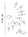
- FIG. 23 is a schematic diagram showing an example of an imaging network system according to a ninth embodiment of the present invention.
- FIG. 1 is a schematic diagram showing a wireless imaging device (imaging Mote) 100 included in the wireless imaging apparatus according to a first embodiment of the present invention.
- the imaging Mote 100 has a spherical lens 1 , an aperture 2 provided in a position of overlapped bottom parts of imaginary 2 hemispherical members divided from the center of the spherical lens 1 , to limit incident light in the imaging Mote 100 , a coil antenna 3 integrally provided with the aperture 2 , and an optical sensor 4 to convert the incident light passed through the aperture 2 into an electric signal in a position around a vertical point on the inner side of one hemispherical member. Further, a wireless communication circuit 4 a , to generate a high frequency signal from image data converted into the electric signal by the optical sensor 4 , is provided on the same substrate of the optical sensor.
- the coil antenna 3 has a terminal (not shown) electrically connected to the wireless communication circuit 4 a , to transmit the high frequency signal generated by the wireless communication circuit 4 a to the outside via the antenna 3 .
- FIG. 2 illustrates a case where the substrate holding the optical sensor 4 and the wireless communication circuit 4 a is provided separately from the spherical lens 1 .
- the aperture 2 has the coil antenna 3 .
- the antenna 3 or a light-emitting device for optical communication can be provided on the rear side of the substrate in FIG. 2 .
- the optical sensor 4 is provided on the inner spherical surface of the spherical lens 1 as shown in FIG. 1 .
- FIGS. 3 to 5 show other examples of the antenna 3 in FIGS. 1 and 2 .
- FIG. 3 shows a coil 31 of the antenna 3 , having an about 3 turns, for higher communication performance.
- FIG. 4 shows the antenna 3 having approximately the same structure as that in FIG. 1 .
- the coil of the antenna 3 having the same 1 turn, is arranged on the outer peripheral side of the aperture 2 , for improvement in communication performance.
- FIG. 5 shows an arrangement where the entire surface of the aperture 2 functions as an antenna 23 .
- the area of the aperture 2 can be most effectively utilized.
- the antenna 23 must be formed of a high-conductivity material as a high-performance antenna.
- the maximum diameter of the coil of the antenna 3 is 1 mm.
- the present invention includes, in its scope, management of image information by a sensing network system constructed with functional device group of plural imaging Motes 100 to perform imaging functions by co-operative work using wireless communication.
- FIG. 6 is an explanatory view showing the manufacturing method of the imaging Mote 100 according to the present embodiment.
- hemispherical resin mold lenses 20 are formed by using a metal mold 50 having plural hemispherical cavities 21 as shown in FIG. 6 .
- the imaging Mote 100 of the present embodiment provided with the aperture 2 and the antenna 3 is completed. Further, by the above manufacturing method, a large number of imaging Motes 100 can be formed at once.
- FIG. 9 is an explanatory view showing the wireless imaging apparatus where plural small spherical imaging Motes 100 are provided on a card substrate 42 .
- the wireless imaging apparatus of the present embodiment has a base 41 , to communicate with the plural imaging Motes 100 and control the imaging Motes 100 , on the substrate 42 .
- the wireless imaging apparatus shown in FIG. 9 has the imaging Motes 100 to receive light 43 from a subject, generate sensing image information from the light and transmit the information via the antenna 3 integrally formed with the internal aperture 2 to the outside, and the base 41 , provided on the card substrate 42 , to receive the sensing image information from the imaging Motes 100 .
- the base 41 performs high image quality processing based on the image information received from the plural imaging Motes 100 , and processing for obtaining 3-dimensional image information by calculation of depth information utilizing a parallax error between the small spherical imaging Motes 100 .
- FIG. 10 is an explanatory view showing another example of the wireless imaging apparatus where the plural small spherical imaging Motes 100 are provided along various directional optical axes so as to obtain a wide angle of image information.
- the wireless imaging apparatus in FIG. 10 has the imaging Motes 100 to receive light 43 a to 43 f from the respective directions, generate sensing image information from the light and transmit the information via the antenna 3 integrally formed with the internal aperture 2 to the outside, and the base 41 to receive the sensing image information from the imaging Motes 100 , combining the information from the respective directions and generate wide-angle image information.
- the base 41 has a function of transmitting a control signal to turn on/off a transmission operation of sensing image information of the wireless communication circuit 4 a of each imaging Mote 100 .
- the base can sequentially obtain image information by scanning the plural imaging Motes 100 by on-controlling the transmission operations in desired imaging Motes 100 .
- the base 41 may be arranged such that the base 41 has a control function of on/off controlling power supply to the wireless communication circuit 4 a of each imaging Mote 100 , and sequentially obtains the image information by scanning the plural imaging Motes 100 by on-controlling the power supply to the wireless communication circuits 4 a of desired imaging Motes 100 .
- it may be arranged such that frequencies of radio signals emitted from the plural imaging Motes 100 are different, and image information is sequentially obtained from the plural imaging Motes 100 by scanning reception frequencies by the base 41 .
- the antenna 3 for wireless communication is integrally formed with the aperture 2 , a predetermined size of the antenna 3 can be ensured without increasing the wireless imaging device in size, and a wireless imaging apparatus having excellent sensing sensitivity to an environmental change can be realized.
- the structure of the imaging device can be simplified and the manufacturing process can be facilitated.
- FIG. 12 is a schematic diagram showing the construction of a wireless communication apparatus according to the present invention.
- the wireless communication apparatus has plural functional devices (imaging Motes 1 ) having a wireless communication function and an imaging function as a functional device group.
- the imaging Motes 1 a to 1 j are provided at random in random directions.
- the imaging Mote 1 performs imaging by gathering light 113 incident on a spherical lens 111 by an optical sensor 112 .
- the obtained image information is wireless-transmitted using e.g. an electromagnetic wave 120 , to a base 10 .
- the optical sensor 112 as shown in FIG. 13 includes a wireless communication unit (not shown).
- FIG. 12 where imaging is performed on a subject 15 , video images obtained by the imaging Motes 1 a , 1 c , 1 e and 1 i directed to the subject 15 are combined by the base 10 .
- the respective imaging Motes 1 have a simple structure where the aperture and the lens position are fixed. That is, a general camera has mechanisms to change the depth of subject with a variable aperture and move the lens position to adjust focus of the lens, whereas the imaging Mote 1 of the present embodiment has a single imaging function without variable part, i.e., the structure is simplified with the respective fixed parts.
- each imaging Mote 1 has a simple structure, when a large number of imaging Motes 1 function as a group, the group functions as a high-performance imaging device.
- the electromagnetic wave 120 is used in wireless communication, however, optical communication may be used in the wireless communication.
- the imaging Mote 1 can be simplified by employing any one of R, G and B color filters as a single filter.
- the base 10 may have the same structure as that of other imaging Motes 1 .
- the wireless communication apparatus does not have an imaging Mote named “base”, but one of the imaging Motes 1 is connected to a network circuit thereby communication with the outside is performed.
- the base 10 is separately provided from the imaging Motes 1 as in the case of the above description.
- FIG. 14 is a schematic diagram showing the structure of the imaging Mote according to a fourth embodiment of the present invention.
- an imaging Mote 34 a small spherical lens 31 is employed, an optical sensor 32 for imaging is arranged around the surface of the spherical lens on the opposite side to the imaging light incident side, and further, a communication circuit 33 to receive a radio wave and transmit a signal from the optical sensor 32 is provided on the same substrate of the sensor around the surface of the spherical lens.
- the substrate has a spherical shape.
- Light 36 incident in parallel to an optical axis 35 is condensed by the small spherical lens 31 in a point 37 around the surface of the lens.
- Light 38 with a field angle is condensed by the small spherical lens 31 on a point 39 around the surface of the lens.
- images are formed on the surfaces of the small spherical lenses.
- the refractive index nd of the small spherical lens 31 is “2”
- collimated light i.e. light at infinity is image-focused around the surface of the lens on the opposite side to the incident side.
- the surface of the spherical lens 31 on the incident side is provided with a filter for selection of particular wavelength, thereby the chromatic aberration an be suppressed.
- photoreception devices having 1-cell diameter of 2 ⁇ m, can be provided.
- the photoreception devices are provided in a small sphere, a stable functional device unsusceptible to external environment can be obtained.
- FIG. 15 shows the small spherical lens 31 having a flat surface on the side of the optical sensor 32 of the sensing Mote 34 .
- the optical sensor 32 has a flat shape, the aberration is increased, however, the circuit can be easily formed on the flat substrate.
- This structure is available in an application in which image quality is not so important.
- the small spherical lens 31 is formed, then the imaging side is ground to a flat surface, and a separately-formed flat substrate is joined to the flat surface. In this manner, the lens can be easily manufactured. That is, the optical sensor 32 , the communication circuit 33 and the like are formed in advance on the flat substrate, thereafter, the substrate is joined to the small spherical lens 31 by adhesive bonding or the like. Further, a light emitting device for optical communication may be provided on the substrate.
- the refractive index of the small spherical lens 31 is not necessarily set to “2”, but the thickness of the flat substrate is set for image formation on the imaging surface.
- FIG. 16 shows an example where, different from the above case where the circuit system is directly formed on the surface of the small spherical lens 31 , a separately-formed substrate 30 , holding electronic circuits such as the optical sensor 32 and the communication circuit 33 , in contact with the small spherical lens 31 , is joined with the lens using adhesive 54 or the like.
- the adhesive 54 constructs a part of the lens system. Influence of aberration increases as the field angle is shifted from the optical axis, however, in some purposes, the image information can be utilized as high resolution image is not required. In this manufacturing, a very low-price sensing Mote 34 can be formed and used for a wide range of purposes.
- FIG. 17 shows an example where, different from the above-described spherical lens, the imaging Mote has an optical lens 6 which is a general convex lens. Incident light is passed through an aperture 7 and is gathered on an optical sensor 8 , and delivered as data by wireless communication from a communication circuit 9 .
- various types of lenses are designed for a wide field angle imaging optical system.
- the image screen size increases, which increases the size of the imaging optical system.
- the amount of ambient light is greatly reduced due to the well-known cosine forth power law.
- a spherical lens As a simple optical system to attain a wide field angle, a spherical lens is conventionally known. Generally, in a lens system having a small curvature and a flat image surface, the size of image surface is infinitely increased as the field angle becomes closer to 180°, and the amount of ambient light reaches to the image surface is greatly reduced. Accordingly, in a conventional fish-eye lens, a large negative curvature aberration is intentionally caused, to attain the 180° field angle and prevent the significant reduction of amount of ambient light. However, as the occurrence of negative curvature aberration equals compression of image in a peripheral portion of the image surface, the resolution is lowered and the image formation performance is degraded.
- the image surface is a spherical surface cocentric with the spherical lens due to spherical symmetric property of the lens. Accordingly, in the spherical lens, axial aberration and off-axial aberration are equal. If approximately excellent aberration correction is attained on the axis, the off-axial aberration can be similarly corrected.
- the focal distance of the spherical lens is f
- the photoreception area of the sensor is 2 ⁇ f 2
- a field angle of 180° can be obtained.
- the degradation of resolution in a lens peripheral portion due to spherical symmetric property of the spherical lens does not occur.
- the great reduction of the amount of ambient light due to the cosine forth-power law in a general lens system does not occur. The amount of ambient light is merely reduced in proportion to the power of the cosine of incident angle.
- this optical system which is smaller and simple in comparison with a general lens system, as reduction of the amount of ambient light is small by appropriate aberration correction, a wide field angle optical system with an entirely bright image surface and excellent image forming performance can be obtained.
- the downsizing of the imaging Mote is important.
- the imaging Mote is constructed with a spherical lens and an optical sensor.
- the aperture 77 is positioned on the incident light side of the spherical lens 66 or positioned inside the spherical lens 66 as shown in FIG. 18B . If the aperture 77 is positioned in the central portion of the spherical lens 66 , a high resolution image can be obtained, the field angle can be increased, and unnecessary light can be eliminated by reduction of coma aberration. Accordingly, more preferably, the aperture 77 is positioned in the central portion of the spherical lens 66 .
- the relation among the resolution R, the wavelength ⁇ , the lens numerical aperture NA, the lens refractive index n, and the aperture (lens effective aperture) D is as follows.
- R k
- ( ⁇ / NA ) k
- ( ⁇ / n tan ⁇ ) k
- [ ⁇ /n ⁇ ( D/ 2)/ L ⁇ ] k
- [2 ⁇ /( nD/L )] k
- the resolution R is improved in proportion to the aperture.
- the focal depth DOF is k2 ⁇ /(NA) 2 ⁇ , and becomes shorter in proportional to the second power of the aperture D.
- the influence of the aberration is greater, high resolution and long depth can be attained when the aperture is small.
- FIGS. 19A to 19C are schematic diagrams showing examples of the imaging Mote.
- the imaging Mote constructed with the spherical lens 66 and the aperture 77 , has different apertures as shown in FIGS. 19A to 19C .
- a large number of imaging Motes having different apertures are provided, and video image data obtained from the respective imaging Motes are transmitted to the base.
- the base selects only a video image from an imaging Mote having the aperture corresponding to an imaging subject and imaging environment and uses the selected video image.
- the same advantage as that obtained by changing the aperture in a single imaging Mote can be obtained.
- the aperture of the camera is normally changed in accordance with an imaging subject, a working distance between the lens and the subject, an imaging environment such as brightness.
- imaging Motes respectively set to several apertures are provided and imaging data is selected in correspondence with the circumstance, thus the aperture can be substantially changed.
- the aperture is changed by selection of imaging Mote.
- the filter of the optical lens can be changed by selection of imaging Mote.
- filters of red (R), blue (B) and green (G) as the 3 primary colors of color image may be provided. Any of the 3 color filters of a CCD sensor may be fixed to each imaging Mote. Otherwise, even in a case where a color optical sensor is not used, if each imaging Mote is constructed with a monochrome optical sensor and a spherical lens with a color-filter, each Mote can output an image of one of the respective colors.
- a filter of any one of cyan, magenta, yellow and green complementary colors may be employed.
- a polarizing filter may be provided.
- a linear polarization or circular polarization filter may be set in the respective imaging Motes, or a combination of these filters with an infrared filter may be used.
- the imaging Mote with a particular polarizing filter is effectively used upon imaging of a subsurface fish or the like.
- FIG. 21 is a schematic diagram showing an example where the refractive index n of the spherical lens is slightly changed in respective imaging Motes.
- a focused state can be obtained in different points in the respective imaging Motes.
- FIGS. 22A to 22C in a system where the small lens 66 and the substrate 30 as shown in FIG. 16 are joined, if imaging surfaces are arbitrarily defocused, a focused state can be obtained by any imaging Mote.
- the present invention is not limited to the spherical lens, but is applicable to imaging Motes using a concave lens, a convex lens and the like.
- images are obtained from a large number of imaging Motes and subjected to image processing, by previously controlling the positions and directions of the respective imaging Motes, or obtaining a mean from a large number of imaging Motes provided at random.
- the imaging Motes are provided at random, however, as shown in FIG. 23 , if the directions of the imaging Motes 1 are controlled to set the lenses toward the imaging subject 15 , the number of effective image data is increased. Further, it is more preferable that the positions of the imaging Motes 1 can be controlled. Note that it is necessary to install a direction control mechanism and/or a moving means into the imaging Mote 1 .
- each functional device has a simple structure, low electric consumption and low cost imaging apparatus can be realized, and a high-level imaging network can be constructed.
Abstract
Description
R=k|(λ/NA)=k|(λ/nsinθ)≅k|(λ/ntanθ) =k|[λ/n{(D/2)/L}]=k|[2λ/(nD/L)]=k|(2λ/Fno)
Claims (12)
Applications Claiming Priority (4)
| Application Number | Priority Date | Filing Date | Title |
|---|---|---|---|
| JP2002-295305(PAT.) | 2002-10-08 | ||
| JP2002295305A JP2004134892A (en) | 2002-10-08 | 2002-10-08 | Wireless imaging apparatus |
| JP2002296596A JP2004134982A (en) | 2002-10-09 | 2002-10-09 | Radio communication apparatus and its driving method |
| JP2002-296596(PAT.) | 2002-10-09 |
Publications (2)
| Publication Number | Publication Date |
|---|---|
| US20040071460A1 US20040071460A1 (en) | 2004-04-15 |
| US7508417B2 true US7508417B2 (en) | 2009-03-24 |
Family
ID=32072506
Family Applications (1)
| Application Number | Title | Priority Date | Filing Date |
|---|---|---|---|
| US10/677,623 Expired - Fee Related US7508417B2 (en) | 2002-10-08 | 2003-10-02 | Wireless imaging apparatus and its control method |
Country Status (2)
| Country | Link |
|---|---|
| US (1) | US7508417B2 (en) |
| CN (2) | CN100413328C (en) |
Cited By (1)
| Publication number | Priority date | Publication date | Assignee | Title |
|---|---|---|---|---|
| CN103104792A (en) * | 2013-01-22 | 2013-05-15 | Tcl集团股份有限公司 | Bionic camera, offset method for driving the bionic camera and media terminal |
Families Citing this family (23)
| Publication number | Priority date | Publication date | Assignee | Title |
|---|---|---|---|---|
| US20050256667A1 (en) * | 2004-05-12 | 2005-11-17 | Searete Llc, A Limited Liability Corporation Of The State Of Delaware | Federating mote-associated log data |
| US20060064402A1 (en) * | 2004-07-27 | 2006-03-23 | Jung Edward K Y | Using federated mote-associated indexes |
| US9261383B2 (en) * | 2004-07-30 | 2016-02-16 | Triplay, Inc. | Discovery of occurrence-data |
| US7929914B2 (en) * | 2004-03-31 | 2011-04-19 | The Invention Science Fund I, Llc | Mote networks using directional antenna techniques |
| US8200744B2 (en) * | 2004-03-31 | 2012-06-12 | The Invention Science Fund I, Llc | Mote-associated index creation |
| US7389295B2 (en) | 2004-06-25 | 2008-06-17 | Searete Llc | Using federated mote-associated logs |
| US7457834B2 (en) * | 2004-07-30 | 2008-11-25 | Searete, Llc | Aggregation and retrieval of network sensor data |
| US8346846B2 (en) | 2004-05-12 | 2013-01-01 | The Invention Science Fund I, Llc | Transmission of aggregated mote-associated log data |
| US20050227686A1 (en) * | 2004-03-31 | 2005-10-13 | Jung Edward K Y | Federating mote-associated index data |
| US9062992B2 (en) * | 2004-07-27 | 2015-06-23 | TriPlay Inc. | Using mote-associated indexes |
| US8161097B2 (en) * | 2004-03-31 | 2012-04-17 | The Invention Science Fund I, Llc | Aggregating mote-associated index data |
| US8275824B2 (en) * | 2004-03-31 | 2012-09-25 | The Invention Science Fund I, Llc | Occurrence data detection and storage for mote networks |
| US8335814B2 (en) * | 2004-03-31 | 2012-12-18 | The Invention Science Fund I, Llc | Transmission of aggregated mote-associated index data |
| US7941188B2 (en) * | 2004-03-31 | 2011-05-10 | The Invention Science Fund I, Llc | Occurrence data detection and storage for generalized sensor networks |
| US20050255841A1 (en) * | 2004-05-12 | 2005-11-17 | Searete Llc | Transmission of mote-associated log data |
| EP2592837A1 (en) * | 2011-11-10 | 2013-05-15 | Research In Motion Limited | Apparatus and associated method for forming color camera image |
| US9599787B2 (en) | 2011-12-27 | 2017-03-21 | Tera Xtal Technology Corporation | Using sapphire lens to protect the lens module |
| US9176602B2 (en) * | 2013-06-11 | 2015-11-03 | Thomson Licensing | Spherical remote control |
| WO2015075072A1 (en) | 2013-11-21 | 2015-05-28 | Sony Corporation | Surveillance apparatus having an optical camera and a radar sensor |
| CN105938244A (en) * | 2016-06-23 | 2016-09-14 | 无锡德斯凯动力科技有限公司 | Industrial endoscope |
| CN107734214A (en) * | 2016-08-10 | 2018-02-23 | 宁波舜宇光电信息有限公司 | With the multi-cam module of different size aperture and its application |
| CN109900393B (en) * | 2019-03-19 | 2021-07-09 | 中国十七冶集团有限公司 | Section steel concrete corridor and safety monitoring method for steel truss reinforced structure thereof |
| JP6798073B2 (en) * | 2019-06-04 | 2020-12-09 | エスゼット ディージェイアイ テクノロジー カンパニー リミテッドSz Dji Technology Co.,Ltd | Mobile body and sensor unit |
Citations (7)
| Publication number | Priority date | Publication date | Assignee | Title |
|---|---|---|---|---|
| US5004328A (en) | 1986-09-26 | 1991-04-02 | Canon Kabushiki Kaisha | Spherical lens and imaging device using the same |
| JPH10271469A (en) | 1997-03-24 | 1998-10-09 | Kyocera Corp | Private branch cordless image communication system |
| US6052509A (en) * | 1996-03-22 | 2000-04-18 | Canon Kabushiki Kaisha | Image pickup apparatus |
| US20020047910A1 (en) * | 1997-02-21 | 2002-04-25 | Motoi Tariki | Image transmission apparatus and method and image transmission system |
| US20030142032A1 (en) * | 2002-01-31 | 2003-07-31 | Lichtfuss Hans A. | Integrated wireless antenna for an image capturing device |
| US20050185195A1 (en) * | 2004-02-20 | 2005-08-25 | Fuji Xerox Co., Ltd. | Positional measurement system and lens for positional measurement |
| US20050219144A1 (en) * | 2002-05-02 | 2005-10-06 | Zhinong Ying | Integrated antenna assembly |
-
2003
- 2003-09-28 CN CNB2005100739917A patent/CN100413328C/en not_active Expired - Fee Related
- 2003-09-28 CN CNB031602266A patent/CN1241401C/en not_active Expired - Fee Related
- 2003-10-02 US US10/677,623 patent/US7508417B2/en not_active Expired - Fee Related
Patent Citations (7)
| Publication number | Priority date | Publication date | Assignee | Title |
|---|---|---|---|---|
| US5004328A (en) | 1986-09-26 | 1991-04-02 | Canon Kabushiki Kaisha | Spherical lens and imaging device using the same |
| US6052509A (en) * | 1996-03-22 | 2000-04-18 | Canon Kabushiki Kaisha | Image pickup apparatus |
| US20020047910A1 (en) * | 1997-02-21 | 2002-04-25 | Motoi Tariki | Image transmission apparatus and method and image transmission system |
| JPH10271469A (en) | 1997-03-24 | 1998-10-09 | Kyocera Corp | Private branch cordless image communication system |
| US20030142032A1 (en) * | 2002-01-31 | 2003-07-31 | Lichtfuss Hans A. | Integrated wireless antenna for an image capturing device |
| US20050219144A1 (en) * | 2002-05-02 | 2005-10-06 | Zhinong Ying | Integrated antenna assembly |
| US20050185195A1 (en) * | 2004-02-20 | 2005-08-25 | Fuji Xerox Co., Ltd. | Positional measurement system and lens for positional measurement |
Non-Patent Citations (1)
| Title |
|---|
| Nikkei Electronics, Jul. 15, 2002, pp. 99 to 129, with English Translation. (Fumitada Takahashi and Hiroki Hohda). |
Cited By (2)
| Publication number | Priority date | Publication date | Assignee | Title |
|---|---|---|---|---|
| CN103104792A (en) * | 2013-01-22 | 2013-05-15 | Tcl集团股份有限公司 | Bionic camera, offset method for driving the bionic camera and media terminal |
| CN103104792B (en) * | 2013-01-22 | 2016-01-27 | Tcl集团股份有限公司 | Bionical camera, the biasing means driving bionical camera and media termination |
Also Published As
| Publication number | Publication date |
|---|---|
| CN100413328C (en) | 2008-08-20 |
| CN1681298A (en) | 2005-10-12 |
| US20040071460A1 (en) | 2004-04-15 |
| CN1241401C (en) | 2006-02-08 |
| CN1497952A (en) | 2004-05-19 |
Similar Documents
| Publication | Publication Date | Title |
|---|---|---|
| US7508417B2 (en) | Wireless imaging apparatus and its control method | |
| US20220003906A1 (en) | Spectral filter, and image sensor and electronic device including the spectral filter | |
| US20220028909A1 (en) | Image sensor and image processing method, and electronic device including the image sensor | |
| US20220342130A1 (en) | Spectral filter, and image sensor and electronic device including spectral filter | |
| US20230176336A1 (en) | Lens assembly and electronic device including the same | |
| US20220342129A1 (en) | Spectral filter, and image sensor and electronic device including spectral filter | |
| US20230068298A1 (en) | Lens assembly and electronic device including same | |
| US20220276459A1 (en) | Camera module and electronic device including the same | |
| US20220128407A1 (en) | Spectral filter, and image sensor and electronic device including the spectral filter | |
| US11848343B2 (en) | Spectral filter, and image sensor and electronic device including the spectral filter | |
| US20230152558A1 (en) | Lens assembly and electronic device including the same | |
| US20240145508A1 (en) | Image sensor and electronic device | |
| JP2004134982A (en) | Radio communication apparatus and its driving method | |
| EP4354194A1 (en) | Lens assembly and electronic device including same | |
| US20240098352A1 (en) | Lens assembly and electronic device comprising same | |
| US20230154132A1 (en) | Method for providing image and electronic device supporting the same | |
| CN216772093U (en) | Imaging lens, imaging module and distance measuring sensor | |
| US20240126054A1 (en) | Lens assembly and electronic device including same | |
| US20240007732A1 (en) | Electronic device including plurality of cameras | |
| US20230139533A1 (en) | Optical sensor including nanophotonic microlens array and electronic device including the same | |
| US20230217122A1 (en) | Spectral filter, and image sensor and electronic device including the spectral filter | |
| EP4239387A1 (en) | Lens assembly and electronic device comprising same | |
| KR20240017688A (en) | Color filter, image sensor, and electronic apparatus having the same | |
| US20230131146A1 (en) | Lens assembly and electronic device including the same | |
| KR20240022950A (en) | Lens assembly and electronic device including the same |
Legal Events
| Date | Code | Title | Description |
|---|---|---|---|
| AS | Assignment |
Owner name: CANON KABUSHIKI KAISHA, JAPAN Free format text: ASSIGNMENT OF ASSIGNORS INTEREST;ASSIGNORS:NISHIMURA, NAOKI;SAITOH, KENJI;SHIBATA, MASAAKI;REEL/FRAME:014607/0485 Effective date: 20030930 |
|
| AS | Assignment |
Owner name: CANON KABUSHIKI KAISHA, JAPAN Free format text: RE-RECORD EXECUTION DATES TO 9/30/03, 9/29/03, 9/29/03 FOR REEL; 014607, 0485;ASSIGNORS:NISHIMURA, NAOKI;SAITOH, KENJI;SHIBATA, MASAAKI;REEL/FRAME:015413/0434;SIGNING DATES FROM 20030929 TO 20030930 |
|
| STCF | Information on status: patent grant |
Free format text: PATENTED CASE |
|
| FPAY | Fee payment |
Year of fee payment: 4 |
|
| FEPP | Fee payment procedure |
Free format text: PAYOR NUMBER ASSIGNED (ORIGINAL EVENT CODE: ASPN); ENTITY STATUS OF PATENT OWNER: LARGE ENTITY |
|
| FPAY | Fee payment |
Year of fee payment: 8 |
|
| FEPP | Fee payment procedure |
Free format text: MAINTENANCE FEE REMINDER MAILED (ORIGINAL EVENT CODE: REM.); ENTITY STATUS OF PATENT OWNER: LARGE ENTITY |
|
| LAPS | Lapse for failure to pay maintenance fees |
Free format text: PATENT EXPIRED FOR FAILURE TO PAY MAINTENANCE FEES (ORIGINAL EVENT CODE: EXP.); ENTITY STATUS OF PATENT OWNER: LARGE ENTITY |
|
| STCH | Information on status: patent discontinuation |
Free format text: PATENT EXPIRED DUE TO NONPAYMENT OF MAINTENANCE FEES UNDER 37 CFR 1.362 |
|
| FP | Lapsed due to failure to pay maintenance fee |
Effective date: 20210324 |