US7512159B2 - Method for variable performance in communication systems - Google Patents
Method for variable performance in communication systems Download PDFInfo
- Publication number
- US7512159B2 US7512159B2 US10/931,665 US93166504A US7512159B2 US 7512159 B2 US7512159 B2 US 7512159B2 US 93166504 A US93166504 A US 93166504A US 7512159 B2 US7512159 B2 US 7512159B2
- Authority
- US
- United States
- Prior art keywords
- data
- levels
- message header
- packet
- level
- Prior art date
- Legal status (The legal status is an assumption and is not a legal conclusion. Google has not performed a legal analysis and makes no representation as to the accuracy of the status listed.)
- Active, expires
Links
- 238000000034 method Methods 0.000 title claims abstract description 40
- 238000004891 communication Methods 0.000 title description 13
- 230000005540 biological transmission Effects 0.000 claims abstract description 34
- 238000012937 correction Methods 0.000 claims description 9
- 230000003068 static effect Effects 0.000 claims description 6
- 230000000007 visual effect Effects 0.000 claims description 5
- 230000010363 phase shift Effects 0.000 claims description 4
- 238000012544 monitoring process Methods 0.000 claims description 2
- 238000010586 diagram Methods 0.000 description 3
- 238000001514 detection method Methods 0.000 description 2
- 230000002452 interceptive effect Effects 0.000 description 2
- 238000001228 spectrum Methods 0.000 description 2
- 230000006978 adaptation Effects 0.000 description 1
- 230000015556 catabolic process Effects 0.000 description 1
- 238000006731 degradation reaction Methods 0.000 description 1
- 230000001419 dependent effect Effects 0.000 description 1
- 238000013461 design Methods 0.000 description 1
- 239000000284 extract Substances 0.000 description 1
- 238000005457 optimization Methods 0.000 description 1
- 238000012546 transfer Methods 0.000 description 1
Images


Classifications
-
- H—ELECTRICITY
- H04—ELECTRIC COMMUNICATION TECHNIQUE
- H04L—TRANSMISSION OF DIGITAL INFORMATION, e.g. TELEGRAPHIC COMMUNICATION
- H04L27/00—Modulated-carrier systems
- H04L27/32—Carrier systems characterised by combinations of two or more of the types covered by groups H04L27/02, H04L27/10, H04L27/18 or H04L27/26
- H04L27/34—Amplitude- and phase-modulated carrier systems, e.g. quadrature-amplitude modulated carrier systems
- H04L27/3488—Multiresolution systems
-
- H—ELECTRICITY
- H04—ELECTRIC COMMUNICATION TECHNIQUE
- H04H—BROADCAST COMMUNICATION
- H04H20/00—Arrangements for broadcast or for distribution combined with broadcast
- H04H20/44—Arrangements characterised by circuits or components specially adapted for broadcast
- H04H20/46—Arrangements characterised by circuits or components specially adapted for broadcast specially adapted for broadcast systems covered by groups H04H20/53-H04H20/95
- H04H20/51—Arrangements characterised by circuits or components specially adapted for broadcast specially adapted for broadcast systems covered by groups H04H20/53-H04H20/95 specially adapted for satellite broadcast systems
-
- H—ELECTRICITY
- H04—ELECTRIC COMMUNICATION TECHNIQUE
- H04H—BROADCAST COMMUNICATION
- H04H40/00—Arrangements specially adapted for receiving broadcast information
- H04H40/18—Arrangements characterised by circuits or components specially adapted for receiving
- H04H40/27—Arrangements characterised by circuits or components specially adapted for receiving specially adapted for broadcast systems covered by groups H04H20/53 - H04H20/95
- H04H40/90—Arrangements characterised by circuits or components specially adapted for receiving specially adapted for broadcast systems covered by groups H04H20/53 - H04H20/95 specially adapted for satellite broadcast receiving
-
- H—ELECTRICITY
- H04—ELECTRIC COMMUNICATION TECHNIQUE
- H04H—BROADCAST COMMUNICATION
- H04H60/00—Arrangements for broadcast applications with a direct linking to broadcast information or broadcast space-time; Broadcast-related systems
- H04H60/09—Arrangements for device control with a direct linkage to broadcast information or to broadcast space-time; Arrangements for control of broadcast-related services
- H04H60/11—Arrangements for counter-measures when a portion of broadcast information is unavailable
-
- H—ELECTRICITY
- H04—ELECTRIC COMMUNICATION TECHNIQUE
- H04L—TRANSMISSION OF DIGITAL INFORMATION, e.g. TELEGRAPHIC COMMUNICATION
- H04L1/00—Arrangements for detecting or preventing errors in the information received
- H04L1/0078—Avoidance of errors by organising the transmitted data in a format specifically designed to deal with errors, e.g. location
- H04L1/0083—Formatting with frames or packets; Protocol or part of protocol for error control
-
- H—ELECTRICITY
- H04—ELECTRIC COMMUNICATION TECHNIQUE
- H04L—TRANSMISSION OF DIGITAL INFORMATION, e.g. TELEGRAPHIC COMMUNICATION
- H04L1/00—Arrangements for detecting or preventing errors in the information received
- H04L2001/0098—Unequal error protection
Definitions
- the present invention generally relates to the transmission of digital data, and more particularly, to the transmission of digital data in a satellite digital audio radio (“SDAR”) system.
- SDAR satellite digital audio radio
- each satellite is at a specific longitude and at a specific latitude. Accordingly, the satellites always seem to be positioned above the same spot on the earth.
- the Sirius satellite system however, three communication satellites are present that orbit the earth along specific longitudes and latitudes and, relative to the northern hemisphere, rise and set once a day (geosynchronous). Consequently, two of the three satellites are “visible” to receivers in the United States at all times. Since both satellite systems provide audio data to mobile receivers in urban canyons and other high population density areas with limited line-of-sight satellite coverage, both systems use terrestrial repeaters to receive and re-broadcast the same user data that is transmitted by the respective satellite systems.
- the present invention provides a method and apparatus for optimizing the throughput (i.e. information) in a digital transmission system by transmitting the different services with different performance levels.
- throughput i.e. information
- Traditionally local communication was done over wires because this presented a cost-effective way of ensuring a reliable transfer of information. Transmission of information over radio waves was needed for long-distance communications. This type of transmission raised doubts over the corruption of the information and was often dependent on high-power transmitters to overcome weather conditions, large buildings, and interference from other sources.
- Modulation is the process of modifying one or more of the attributes of the radio wave (carrier) in accordance with the information to be conveyed.
- Demodulation is the reciprocal process carried out in the receiver in order to reconstruct the original information. This information could be, for example, computer data, audio data or a television program.
- modulation techniques such as A.M. (amplitude modulation), F.M. (frequency modulation), and P.M. (phase modulation), represent different ways to shape or form electromagnetic radio waves. There are many reasons to modulate a signal in a particular way.
- Amplitude modulation produces a simple, robust wave that doesn't use much spectrum or radio bandwidth and is simpler to demodulate. However, it is plagued by noise and requires high transmitting power.
- Frequency modulation such as analog cell phones use, provides better sound but it needs more bandwidth to achieve that quality and is technically more complex to produce.
- the various modulation techniques offered different solutions in terms of cost-effectiveness and quality of received signals but until recently were still largely analog.
- digital modulation techniques such as GSM and IS-136, come all the advantages that traditional microprocessor circuits have over their analog counterparts. Many shortfalls in the communications link can be compensated or eradicated by using digital techniques.
- the present invention addresses the need in the art to vary the performance of different services (i.e., levels of data). Because the performance of the primary level of data will not be equal to the performance of the secondary level of data, the primary level will need to be further protected.
- the primary level data may be streaming data.
- the secondary level data does not need as much protection because it may be rebroadcast repeatedly. The easiest and most cost effective solution is to integrate multiple symbols for a secondary level bit. Another method would be to use different forward error correction algorithms.
- the present invention provides a method and apparatus where the protection given can be varied by data packets or data frames. Although data can be transmitted one character at a time, it is more efficient to send information in larger blocks called data packets or frames.
- the present invention provides a method and apparatus unlike other systems today.
- the maximum data rate of a modem is limited by the available frequency range (bandwidth) and signal-to-noise ratio (SNR). Noise may be defined as the combination of unwanted interfering signal sources such as cross-talk or radio frequency interference. Noise impairs the detection of the smallest analog levels that may be resolved. If more bandwidth or SNR is available to the modem, more bits may be transferred per second.
- the present invention provides a method and apparatus in which the power level for the data levels can be set within each data packet providing the different services with different levels of performance.
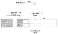
- FIG. 1 is a schematic diagram of a data packet
- FIG. 2 is a schematic diagram of a message header
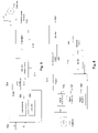
- FIG. 3 is a flow chart diagram of the inventive method for receiving
- FIG. 4 is a schematic representation of the inventive method for transmitting
- FIG. 5 is a diagrammatic representation of the inventive transmitting systems.
- FIG. 6 is a diagrammatic representation of the inventive receiving systems.
- “Hierarchical modulation” hereinafter describes when two separate data or bit streams are modulated onto a single transmission stream. Essentially, a “high priority” stream is superimposed upon, mapped on, or embedded within a “low priority” data stream (or vice versa). The high priority stream may have a lower data rate than the low priority stream while also being more robust. By using a lower code rate (i.e., the ratio of the transmitted bit rate to the useful bit rate) the bits of the high priority stream may also be transmitted with a greater error protection than those bits of the low priority stream. Broadcasters of SDAR services may also use the high and low priority streams to target different types of receivers.
- First level data refers to existing data that may be interpreted by current (i.e., “legacy”) SDAR receivers.
- First level, or primary, data may either perform the same as or differently from second level, or secondary, data.
- Second level data refers to the additional data that is superimposed on the first level data to create a hierarchical modulated data stream.
- Second level, or secondary, data may either perform the same as (e.g., lower data rate) or perform differently from (e.g., higher data rate) first level, or primary, data.
- FIG. 1 shows message header 102 and two levels of data 104 , 106 .
- Message header 102 is typically located at the beginning of data packet 100 and contains information regarding data packet 100 , which may include format and coding information.
- First level data 104 and second level data 106 are shown representing different types of required services.
- Message header 102 may be broken into separate first and second headers or the message header for 106 may be included in reserved bits in 104 .
- the present invention includes a method for receiving a data transmission signal and determining the beginning and end of a data packet.
- a digital transmission system is a transmission system in which all circuits carry digital (i.e. characterized by discreet states) signals and the signals are combined into one or more serial bit streams. Data is transmitted in blocks called data packets. Once the beginning and ending of the data packet have been determined, the data packet is then decoded.
- the decoding process involves differentiating between two levels of data and separately demodulating each of the two levels of data (demodulation may also include forward error correction (FEC) decoding). The two levels of data may be different types of required services.
- FEC forward error correction
- a method uses a message header.
- a message header (or packet header) is control information placed before data when encapsulating that data for network transmission.
- the process involves decoding the data packet by differentiating between a message header and two levels of data in the data packet.
- the message header may include information about the data packet and error checking information.
- the message header will also include instructions for decoding the two levels of data.
- the message header will be read according to an established protocol.
- the next step is demodulating the two levels of data according to the instructions given in the message header.
- FIG. 2 depicts message header 200 with two different types of information: data packet information 202 and data level information 204 .
- Data packet information 202 includes instructions about the data carried by the packet. These instructions may include: length of packet, packet number (which packet this is in a sequence of packets), protocol (on networks that carry multiple types of information, the protocol defines what type of packet is being transmitted), destination address (where the packet is going), and originating address (where the packet came from).
- Data level information 204 includes instructions on demodulating the two levels of data. The two levels of data may be provided with a different energy per symbol levels providing different service priorities for the respective levels.
- a method for decoding the two levels of data encoded with a different amount of energy per symbol is provided.
- each service can be optimized for the desired level of priority and performance. This optimization can be accomplished by using the same detection circuitry for each type of information.
- each piece of information can have a different energy level. This would work especially well for hierarchical modulation systems where the secondary level symbol energy is not as large as the primary level symbol energy. This allows adjustment of the secondary level symbol energy to minimize the degradation seen by legacy receivers that only process the primary level symbol energy.
- a method which further comprises the steps of monitoring periodically for symbols in one of the two levels of data and determining the receipt of specific information in the second level of data and transmitting the specific information in the second level of data to an information device, such as an SDAR receiver.
- the specific information may include static rebroadcast data such as current time, weather updates, and news updates. Puncture codes (a type of forward error correction) can be used to minimize the time required to receive rebroadcast data (Digital Fountain is one example of a Puncture code).
- FIG. 3 An embodiment of this inventive method of receiving and decoding such transmissions is shown in FIG. 3 .
- the data transmission signal is received ( 302 ).
- the beginning and ending of data packet is determined ( 304 ).
- the next step is to differentiate between the two levels of data and message header ( 306 ) and to demodulate the message header to determine the two levels of data and instructions for decoding the two levels of data ( 308 ).
- the two levels of data which are encoded with a different amount of energy per symbol, are demodulated according to instructions read from the message header ( 310 ).
- the next step is to monitor periodically for symbols in one of the two levels of data ( 312 ) and when receipt of the specific information is completed ( 314 ), the specific information is transmitted to an information device ( 316 ). In the case of streaming data, ( 312 ) passes the data directly to ( 316 ).
- an apparatus for receiving a data packet in a digital transmission system includes a digital transmission receiver, including a device for determining the beginning and end of a data packet.
- the apparatus further includes a signal decoder to differentiate between the two levels of data.
- the two levels of data may include different types of services.
- the apparatus further includes a device for demodulating each of the two levels of data.
- an apparatus with a signal decoder for differentiating between a message header and two levels of data in the data packet is provided.
- the signal decoder of the apparatus further includes a device for distinguishing the message header to determine the two levels of data and instructions for decoding the two levels of data.
- the apparatus further includes a device for demodulating the two levels of data according to the instructions read from the message header.
- an apparatus including a signal decoder with a device for decoding the two levels of data encoded with a different amount of energy per symbol.
- a level of data with more energy per symbol will have more protection from noise.
- Noise may be defined as the combination of unwanted interfering signal sources such as cross-talk or radio frequency interference.
- an apparatus including a monitor that periodically checks for a second level of data.
- the monitor includes programming that determines the receipt of specific information in the second level of data.
- Static second level data may include such things as the current time, weather updates, or news updates. The monitor will continue checking for the second level of data and determine the receipt of specific information in the second level of data.
- an apparatus including a transmitter adapted to transmit the specific information in the second level of data to an information device.
- a transmitter will transmit the specific information in the second level of data to an information device.
- the second level of data will be rebroadcast and may include such things as the current time, weather updates, and news updates.
- an apparatus including a signal discriminator.
- the signal discriminator includes circuitry for determining the beginning and ending of a data packet.
- the signal discriminator is the part of the receiver that extracts the desired signal from an incoming wave. In order to demodulate a data packet, the beginning and ending of the data packet must first be determined.
- an apparatus including a signal comparator.
- the signal comparator includes circuitry for determining the existence of a message header. If a message header exists, it will include instructions for demodulating the two levels of data.
- the transmitting system includes at least five components.
- the transmitting system includes coder 504 for encoding two levels of data (a and b, 502 ) with a different amount of energy per symbol (different levels of protection from noise).
- Header creator 506 includes circuitry adapted to create a message header (or packet header) including instructions for demodulating the data packets.
- Formatter 508 includes means for inserting instructions for demodulating the two levels of data into the message header 510 .
- Modulator 512 may receive inputs 502 from coder 504 or alternative means. Modulator 512 is adapted to combine message header 510 and inputs 502 using PSK modulation.
- Transmitter 514 is adapted to transmit the modulated signal 516 , possibly to antenna 518 .
- the receiving system of FIG. 6 includes at least seven components.
- Digital transmission receiver 520 is adapted to receive the modulated signal from a transmission, possibly utilizing antenna 519 .
- Receiver 520 includes signal discriminator 522 and signal detector 524 .
- Signal discriminator 522 includes circuitry for determining the beginning and ending of a data packet.
- Signal detector 524 includes circuitry for determining the existence of a message header coupled to signal discriminator.
- Receiver 520 also includes signal decoder 526 , including circuitry for differentiating between two levels of data, and circuitry for demodulating each of the two levels of data.
- Receiver 520 sends demodulated data 528 to speaker 530 .
- Monitor 532 periodically checks for a second level of data in the data packets received by the receiver.
- Monitor 532 includes programming which determines the completion of receipt of specific information in the second level of data. When the specific information data is fully received, the specific information is provided to information device 534 .
- a method for transmitting a data packet having two different inputs in a digital transmission system comprises the steps of combining the inputs by modulating the inputs into data structured and arranged as a data packet and transmitting the modulated data packet.
- the first input may be streaming audio/visual data and the second input may be static data such as the current time, weather updates, or news updates. Modulating the inputs into a data packet will combine the two inputs and the data packet will then be transmitted.
- a method further comprising steps of combining a message header and inputs by modulating the message header and inputs using phase shift keying (PSK) into data structured and arranged as a data packet, is provided.
- PSK involves changing the phase of the transmitted waveform instead of the frequency.
- a phase-modulated waveform can be generated by using the digital data to switch between signals of equal frequency but different phase.
- a method further comprising steps of encoding the inputs with a different amount of energy per symbol and inserting instructions for demodulating the two levels of data into the message header.
- the two levels of data may require different levels of protection.
- the primary level of data may be provided with a higher energy per symbol levels than the secondary level, giving the primary level more protection from noise (outside interferences).
- Two input data streams ( 402 , 404 ) are encoded with a different amount of energy per symbol ( 406 ).
- a message header is created including instructions for demodulating the data packets ( 408 ).
- the instructions for demodulating the two levels of data are inserted into the message header ( 410 ).
- the message header and inputs are combined using PSK modulation into a transmission packet ( 412 ).
- the packet is then transmitted ( 414 ).
- a method wherein the inputs include streaming audio/visual data as a first level of data and static data as a second level of data is provided.
- the primary level of data may include streaming audio/visual data deemed to require more protection. Since the assumption is the second level of data will be rebroadcast and is less important, it may be provided with a lower power level and, therefore, less protection.
- an apparatus further comprising circuitry adapted to create a message header including instructions for demodulating the data packets.
- the modulator is adapted to combine the message header and inputs using phase shift keying (PSK) into data structured and arranged as a transmission packet.
- PSK phase shift keying
- an apparatus further comprising a device for encoding each of the two levels of data with a different amount of energy per symbol, and with a device for inserting instructions for demodulating the two levels of data into message header is provided.
Abstract
Description
Claims (21)
Priority Applications (2)
| Application Number | Priority Date | Filing Date | Title |
|---|---|---|---|
| US10/931,665 US7512159B2 (en) | 2004-09-01 | 2004-09-01 | Method for variable performance in communication systems |
| EP05076984A EP1633070A3 (en) | 2004-09-01 | 2005-08-29 | Transmission of services with different performance levels |
Applications Claiming Priority (1)
| Application Number | Priority Date | Filing Date | Title |
|---|---|---|---|
| US10/931,665 US7512159B2 (en) | 2004-09-01 | 2004-09-01 | Method for variable performance in communication systems |
Publications (2)
| Publication Number | Publication Date |
|---|---|
| US20060045140A1 US20060045140A1 (en) | 2006-03-02 |
| US7512159B2 true US7512159B2 (en) | 2009-03-31 |
Family
ID=35478895
Family Applications (1)
| Application Number | Title | Priority Date | Filing Date |
|---|---|---|---|
| US10/931,665 Active 2026-10-10 US7512159B2 (en) | 2004-09-01 | 2004-09-01 | Method for variable performance in communication systems |
Country Status (2)
| Country | Link |
|---|---|
| US (1) | US7512159B2 (en) |
| EP (1) | EP1633070A3 (en) |
Families Citing this family (2)
| Publication number | Priority date | Publication date | Assignee | Title |
|---|---|---|---|---|
| DE102007053828B4 (en) * | 2007-11-12 | 2009-06-18 | Infineon Technologies Ag | Transmission of coded data |
| CN104081747B (en) * | 2013-01-17 | 2017-05-31 | 华为技术有限公司 | Transmit method, the encoding apparatus and decoding apparatus of HTTP message |
Citations (3)
| Publication number | Priority date | Publication date | Assignee | Title |
|---|---|---|---|---|
| US5757416A (en) * | 1993-12-03 | 1998-05-26 | Scientific-Atlanta, Inc. | System and method for transmitting a plurality of digital services including imaging services |
| US6885679B1 (en) * | 2000-09-29 | 2005-04-26 | Nortel Networks Limited | System and method for layer 2 frame delineation recovery |
| US20050180509A1 (en) * | 2002-01-18 | 2005-08-18 | Koninklijke Philips Electronics N.V. | Robust signal coding |
-
2004
- 2004-09-01 US US10/931,665 patent/US7512159B2/en active Active
-
2005
- 2005-08-29 EP EP05076984A patent/EP1633070A3/en not_active Withdrawn
Patent Citations (3)
| Publication number | Priority date | Publication date | Assignee | Title |
|---|---|---|---|---|
| US5757416A (en) * | 1993-12-03 | 1998-05-26 | Scientific-Atlanta, Inc. | System and method for transmitting a plurality of digital services including imaging services |
| US6885679B1 (en) * | 2000-09-29 | 2005-04-26 | Nortel Networks Limited | System and method for layer 2 frame delineation recovery |
| US20050180509A1 (en) * | 2002-01-18 | 2005-08-18 | Koninklijke Philips Electronics N.V. | Robust signal coding |
Non-Patent Citations (3)
| Title |
|---|
| "Digital Radio Mondiale (DRM): System Specification; ETSI ES 201 980", ETSI Standards, Lis, Sophia Antipolis, Cedex, France, vol. BC, No. V2.1.1, Jun. 1, 2004. |
| Bradley M J: "Digital Radio Mondiale: system and receivers", Ninth International Conference On JF Radio Systems and Techniques, 2003, pp. 198-202, XP002493874, London, UK. |
| Hansen C, et al: Digital radio mondiale (drm) digital sound broadcasting in the am bands, IEEE Transactions On Broadcasting, IEEE Service Center, Piscataway, NJ, US, vol. 40, No. 3, Sep. 1, 2003, pp. 319-328, XP011101427. |
Also Published As
| Publication number | Publication date |
|---|---|
| EP1633070A2 (en) | 2006-03-08 |
| US20060045140A1 (en) | 2006-03-02 |
| EP1633070A3 (en) | 2008-10-22 |
Similar Documents
| Publication | Publication Date | Title |
|---|---|---|
| US7778335B2 (en) | Method and system for hierarchical modulation and demodulation for digital radio | |
| US8369774B2 (en) | Terrestrial transmitting station for transmitting a terrestrial broadcast signal, satellite-aided broadcast system and receiver for a satellite-aided broadcast system | |
| US10110298B2 (en) | Techniques for providing broadcast services on spot beam satellites | |
| US7656966B2 (en) | Method to increase performance of secondary data in a heirarchial modulation scheme | |
| US8520756B2 (en) | PHY sub-channel processing | |
| EP1705853B1 (en) | Demodulation of amplitude information in differentially modulated OFDM signals | |
| US7386056B2 (en) | Method to increase performance of secondary data in a hierarchical modulation scheme | |
| EP1690341B1 (en) | Method to optimize hierarchical modulation for a diversity system | |
| US20060013120A1 (en) | Method and apparatus for providing local channels in a global satellite/terrestrial network | |
| US7830983B2 (en) | Method to minimize degradation in a D-MPSK hierarchical modulation system | |
| EP1633070A2 (en) | Transmission of services with different performance levels | |
| EP1729473B1 (en) | Single frequency network optimization by phase and amplitude offset | |
| Yi | TDM framing for gap filler operation in satellite digital multimedia broadcasting System A | |
| KR20040076906A (en) | Classifying method of gap filler signal in satellite DAB system |
Legal Events
| Date | Code | Title | Description |
|---|---|---|---|
| AS | Assignment |
Owner name: DELPHI TECHNOLOGIES, INC., MICHIGAN Free format text: ASSIGNMENT OF ASSIGNORS INTEREST;ASSIGNORS:WALKER, GLENN A.;DIBIASO, ERIC A.;HIATT, JR., MICHAEL L.;REEL/FRAME:015764/0651 Effective date: 20040827 |
|
| STCF | Information on status: patent grant |
Free format text: PATENTED CASE |
|
| FPAY | Fee payment |
Year of fee payment: 4 |
|
| FPAY | Fee payment |
Year of fee payment: 8 |
|
| AS | Assignment |
Owner name: APTIV TECHNOLOGIES LIMITED, BARBADOS Free format text: ASSIGNMENT OF ASSIGNORS INTEREST;ASSIGNOR:DELPHI TECHNOLOGIES INC.;REEL/FRAME:047143/0874 Effective date: 20180101 |
|
| MAFP | Maintenance fee payment |
Free format text: PAYMENT OF MAINTENANCE FEE, 12TH YEAR, LARGE ENTITY (ORIGINAL EVENT CODE: M1553); ENTITY STATUS OF PATENT OWNER: LARGE ENTITY Year of fee payment: 12 |
|
| AS | Assignment |
Owner name: APTIV TECHNOLOGIES (2) S.A R.L., LUXEMBOURG Free format text: ENTITY CONVERSION;ASSIGNOR:APTIV TECHNOLOGIES LIMITED;REEL/FRAME:066746/0001 Effective date: 20230818 Owner name: APTIV MANUFACTURING MANAGEMENT SERVICES S.A R.L., LUXEMBOURG Free format text: MERGER;ASSIGNOR:APTIV TECHNOLOGIES (2) S.A R.L.;REEL/FRAME:066566/0173 Effective date: 20231005 Owner name: APTIV TECHNOLOGIES AG, SWITZERLAND Free format text: ASSIGNMENT OF ASSIGNORS INTEREST;ASSIGNOR:APTIV MANUFACTURING MANAGEMENT SERVICES S.A R.L.;REEL/FRAME:066551/0219 Effective date: 20231006 |