US7525589B2 - Video outputting method and device - Google Patents
Video outputting method and device Download PDFInfo
- Publication number
- US7525589B2 US7525589B2 US10/926,061 US92606104A US7525589B2 US 7525589 B2 US7525589 B2 US 7525589B2 US 92606104 A US92606104 A US 92606104A US 7525589 B2 US7525589 B2 US 7525589B2
- Authority
- US
- United States
- Prior art keywords
- image
- standard
- aspect ratio
- video
- outputting
- Prior art date
- Legal status (The legal status is an assumption and is not a legal conclusion. Google has not performed a legal analysis and makes no representation as to the accuracy of the status listed.)
- Active, expires
Links
Images


Classifications
-
- H—ELECTRICITY
- H04—ELECTRIC COMMUNICATION TECHNIQUE
- H04N—PICTORIAL COMMUNICATION, e.g. TELEVISION
- H04N7/00—Television systems
- H04N7/01—Conversion of standards, e.g. involving analogue television standards or digital television standards processed at pixel level
-
- H—ELECTRICITY
- H04—ELECTRIC COMMUNICATION TECHNIQUE
- H04N—PICTORIAL COMMUNICATION, e.g. TELEVISION
- H04N7/00—Television systems
- H04N7/01—Conversion of standards, e.g. involving analogue television standards or digital television standards processed at pixel level
- H04N7/0117—Conversion of standards, e.g. involving analogue television standards or digital television standards processed at pixel level involving conversion of the spatial resolution of the incoming video signal
- H04N7/0122—Conversion of standards, e.g. involving analogue television standards or digital television standards processed at pixel level involving conversion of the spatial resolution of the incoming video signal the input and the output signals having different aspect ratios
-
- H—ELECTRICITY
- H04—ELECTRIC COMMUNICATION TECHNIQUE
- H04N—PICTORIAL COMMUNICATION, e.g. TELEVISION
- H04N5/00—Details of television systems
- H04N5/222—Studio circuitry; Studio devices; Studio equipment
- H04N5/262—Studio circuits, e.g. for mixing, switching-over, change of character of image, other special effects ; Cameras specially adapted for the electronic generation of special effects
- H04N5/2628—Alteration of picture size, shape, position or orientation, e.g. zooming, rotation, rolling, perspective, translation
Definitions
- the present invention relates to a video outputting method and device. More particularly, the present invention relates to a video outputting method and device capable of causing a display device to display images with acceptable quality without flickers.
- a standard image has a standard aspect ratio of 4/3
- a widescreen (wide) image has a widescreen (wide) aspect ratio of 16/9, which is horizontally longer than the standard aspect ratio.
- the format of the widescreen image is widely used in video software and broadcast of high-vision or wide clear vision.
- Video outputting devices such as suggested in JP-A 4-091572 and JP-A 6-268932, have compatibility, and output video signals to a camera, video player, and a widescreen (wide) display device of which a format is the widescreen aspect ratio.
- the use of the widescreen aspect ratio has remarkably been spread.
- the video outputting device can output video signal in a suitable form to a standard display device having the standard aspect ratio and the widescreen display device.
- a conventional type of the standard display device is not suitable for the use of the widescreen image. An error is likely to occur in the standard display device if receiving data of the widescreen image.
- outputting of a video signal of the widescreen image at the standard aspect ratio is effective in reception of the widescreen image by way of the standard image.
- the standard display device displays an image on its display region in an unchanged form of the video signal. Therefore, the aspect ratio of the display region for the standard image is equal to that of the standard image.
- the standard image is displayed fully by use of the display region of the standard display device.
- the widescreen image together with the upper and lower blank masked regions is displayed on the display region according to the video signal.
- the widescreen display device is constructed to check existence or lack of the upper and lower blank masked regions in response to a video signal, and discerns the widescreen image from the standard image.
- the upper and lower blank masked regions are cut away in the widescreen display device to set an aspect ratio according to the video signal equal to that of the display region. Therefore, the widescreen image appears fully in the display region.
- Each of the digital still camera is provided with a video output terminal, which outputs a video signal of an image to a display panel disposed on the rear of a camera body for displaying images on the display panel. If an external display device disconnected with the video output terminal, the camera user is enabled to observe various image by use of the display region of a large side on the external display device.
- the widescreen display device requires data processing for discernment of the widescreen image from the standard image for the purpose of the displaying operation. If a slide show is desired by outputting of a sequence of plural images including irregularly arranged sets of the standard image and the widescreen image, delay in the processing is likely to cause flickers on the display region, which cannot be watched in an acceptably comfortable manner during the intermediate periods between plural images.
- an object of the present invention is to provide a video outputting method and device capable of causing a display device to display images with acceptable quality without flickers.
- a video outputting method of outputting video signals to an external display device including a video signal of a standard image having a standard aspect ratio, and a video signal of a wide image having a wide aspect ratio that is horizontally longer than the standard aspect ratio.
- the video outputting method when outputting of the wide image is designated, upper and lower blank masked regions are added outside and along upper and lower edges of the wide image, to convert into a first processed image of the standard aspect ratio, for outputting a video signal associated therewith.
- a lateral blank masked region is added outside and along a lateral edge of the standard image maintained at the standard aspect ratio, to create an image of the wide aspect ratio, wherein the upper and lower blank masked regions are added outside and along upper and lower edges of the image, to create a second processed image, for outputting a video signal associated therewith.
- a video outputting method for displaying at least a first image having a first aspect ratio, and a second image having a second aspect ratio that is horizontally longer than the first aspect ratio.
- upper and lower blank masked regions are created along and outside upper and lower edges of the first and second images irrespective of the first and second aspect ratios being different, in order to create first and second processed images by addition of the upper and lower blank masked regions, for outputting to a display device.
- a lateral blank masked region is created along and outside at least one of first and second lateral edges of the first image, the first processed image being created further by addition of the lateral blank masked region.
- the first and second aspect ratios are respectively a standard aspect ratio and a wide aspect ratio
- the first and second images are respectively a standard image and a wide image.
- the first and second processed images have the first aspect ratio.
- the display device has a display region of the second aspect ratio, and in response to a video signal of the first and second processed images, cuts off the upper and lower blank masked regions, displays respectively the first and second images, and displays the lateral blank masked region together with the first image.
- a specific output mode and a normal output mode are predetermined in a selectively settable manner.
- the specific output mode is set, the first or second processed image is output, and when the normal output mode is set, the first and second images are output without use of the first or second processed image.
- mode information of the specific and normal output modes is displayed visually.
- a selected one of the specific and normal output modes is designated by use of the mode information.
- the lateral blank masked region is created along and outside each of the first and second lateral edges.
- the lateral blank masked region is created along and outside the first lateral edge.
- additional information is displayed in the lateral blank masked region in relation to the first image, the additional information having a form of a character, number, indicia and/or pattern.
- a video outputting device includes an image processing section for creating upper and lower blank masked regions along and outside upper and lower edges of the first and second images irrespective of the first and second aspect ratios being different, in order to create first and second processed images by addition of the upper and lower blank masked regions, for outputting to a display device.
- the image processing section creates a lateral blank masked region along and outside at least one of first and second lateral edges of the first image, the first processed image being created further by addition of the lateral blank masked region.
- the image processing section is set in a selected one of a specific output mode and a normal output mode, and when set in the specific output mode, transmits an output of the first or second processed image, and when set in the normal output mode, transmits an output of the first and second images without creation of the first or second processed image.
- the image processing section further produces additional information having a form of a character, number, indicia and/or pattern, in relation to the first or second image, and positioned in the lateral blank masked region.
- the video outputting device comprises a digital camera.
- an output mode selector is externally operable, for selectively designating one of the specific and normal output modes.
- the output mode selector includes a camera display panel for displaying a mode selection pattern constituted by information of the specific and normal output modes.
- a pointer selects one of the specific and normal output modes by use of the mode selection pattern.
- an aspect ratio selector selects one of the first and second aspect ratios, so as to create either of the first and second images according thereto.
- the output mode selector is constituted by the aspect ratio selector, and when the first aspect ratio is selected, selects the normal output mode, and when the second aspect ratio is selected, selects the specific output mode.
- FIG. 1 is a perspective view illustrating a digital still camera
- FIG. 2A is an explanatory view illustrating processed images of a normal output mode by use of a widescreen display device
- FIG. 2B is an explanatory view illustrating the same as FIG. 2A but by use of a standard display device;
- FIG. 3A is an explanatory view illustrating processed images of a specific output mode by use of the widescreen display device
- FIG. 3B is an explanatory view illustrating the same as FIG. 3A but by use of a standard display device
- FIG. 4 is an explanatory view illustrating a menu pattern of a mode selection menu of output modes
- FIG. 5A is an explanatory view illustrating one preferred embodiment in which a single lateral blank masked region is added
- FIG. 5B is an explanatory view illustrating a state of the widescreen display device displaying the standard image
- FIG. 5C is an explanatory view illustrating a state of the standard display device displaying the standard image
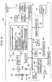
- FIG. 6 is a block diagram schematically illustrating circuitry of the digital camera
- FIG. 7 is a flow chart illustrating a process of producing processed images.
- FIG. 1 a digital still camera 10 as a video outputting device is illustrated.
- a lens barrel protrudes from a front of a camera body 11 , and constitutes an image pickup unit 12 .
- a top of the digital still camera 10 is provided with a power button 13 and a shutter button 14 .
- the rear of the digital still camera 10 is provided with an LCD display panel 15 , a viewfinder eyepiece window 16 , general-purpose keys 17 , a camera mode selector 18 , a menu button 19 , a canceling button 21 and an aspect ratio selector 22 .
- the camera mode selector 18 is used for a selective designation of an image pickup mode and a playing mode.
- photographed images are written to a memory card.
- playing mode images are read from the memory card, and displayed on a display panel.
- the LCD display panel 15 or camera display panel is used for displaying an image, and at the time of the image pickup mode, also operates as an electronic viewfinder for displaying a live image for being framed.
- the LCD display panel 15 further displays a menu pattern of a setting menu for determining settings or conditions.
- the menu button 19 When the menu button 19 is depressed, the digital still camera 10 is changed over to a setup mode from one of the image pickup mode and playing mode, for the LCD display panel 15 to display the setting menu. This makes it possible to determine various parameters, characteristics and conditions, including exposure amount, color hue, ISO sensitivity, pixel number of recording, setting of a self-timer, selection of photometric settings, existence or lack of use of the digital zoom.
- the digital still camera 10 is operated as conditioned by use of the menu pattern of the setting menu.
- the menu button 19 is operable for a confirming and executing button for a selected item or processing after entry.
- the canceling button 21 is used to cancel the item or processing being selected if a user wishes cancellation.
- the general-purpose keys 17 are operable as a pointer or cursor shifting key for moving a cursor (See FIG. 4 ) for selection of an image to be played, or selection of one of items in the menu pattern of the setting menu.
- the general-purpose keys 17 include left and right keys for moving the cursor horizontally, and vertical shifting key for moving the cursor vertically.
- the left and right keys are pushbuttons.
- the vertical shifting key is rotatable about a pivotal axis extending horizontally.
- the vertical shifting key is operable as a zoom button when an image pickup mode is set.
- the aspect ratio selector 22 is used to change over the aspect ratio of a frame of the photographed images, and sets a selected one of 4/3 as a standard aspect ratio and 16/9 as a widescreen aspect ratio. It is possible with the aspect ratio selector 22 for a user to select one of the two aspect ratios according to a scene to be picked up.
- the photographed images are respectively written as a standard image or widescreen image according to the selected aspect ratio.
- scanning of a CCD image sensor 58 in an image pickup unit in FIG. 6 can be changed over. Then the number of the pixels of the object image is adjusted to change the aspect ratio. Furthermore, image processing may be used after retrieval of an object image at a predetermined number of pixels. An image portion of a second one of the aspect ratios is extracted from the image of a first one of the aspect ratios.
- the digital still camera 10 has a construction of the use of the latter. Irrespective of a position of the aspect ratio selector 22 , the CCD image sensor 58 retrieves an object image constantly at a standard aspect ratio. If the aspect ratio selector 22 is positioned to set a widescreen aspect ratio, then an image portion with a format of 16/9 is extracted from the standard image. The digital still camera 10 records the extracted image portion as a widescreen image.
- a video output terminal 24 is disposed on a lateral face of the camera body 11 .
- the video output terminal 24 sends a composite video signal to a widescreen (wide) display device 31 or a standard display device 32 , the composite video signal being a combination of a brightness signal (Y) and a color difference signal (C).
- the video output terminal 24 outputs a video signal of a live image or through image.
- the video output terminal 24 outputs a video signal of a photographed image being read from a memory card 51 .
- the widescreen or standard display device 31 or 32 being external is connected with the video output terminal 24 , so it is possible on a large display area for a user to view photographed images or to monitor a live image.
- the digital still camera 10 operates in a selected one of two output modes for outputting a video signal from the video output terminal 24 .
- a first one of those is a normal output mode as illustrated in FIGS. 2A and 2B .
- a second one of them is a specific output mode as illustrated in FIGS. 3A and 3B .
- the normal output mode is a condition known in the prior art.
- a standard image NP is output as a processed image OPN 1 without changes.
- a widescreen image WP is provided with upper and lower blank masked regions 33 a and 33 b added to the outside of upper and lower edges, to produce a processed image OPW, which is converted to a video signal.
- FIG. 2A the use of the normal output mode is illustrated, in which a video signal is sent to the widescreen display device 31 for displaying an image.
- the processed images OPW and OPN 1 are checked for their video signals, to detect one of the aspect ratios according to existence or lack of the upper and lower blank masked regions 33 a and 33 b . If the video signal is associated with a processed image OPW, then the upper and lower blank masked regions 33 a and 33 b are cut away. This changes the processed image OPW to an image with an aspect ratio equal to 16/9, namely that of a widescreen (wide) display region 31 a . The widescreen image WP is displayed at the full extension. If the video signal is associated with the processed image OPN 1 , then two lateral blank masked portions are added to the outside of the lateral edges, to set the aspect ratio of the processed image OPN 1 equal to that of the widescreen display region 31 a.
- FIG. 2B the use of the normal output mode is illustrated, in which a video signal is sent to the standard display device 32 for displaying an image.
- a standard display region 32 a with a standard aspect ratio displays the processed images OPW and OPN 1 in the standard display device 32 without changes.
- An aspect ratio of the processed image OPN 1 is the standard aspect ratio of 4/3, and equal to that of the standard display device 32 .
- the processed image OPN 1 appears in the full area of the standard display region 32 a .
- the processed image OPW is displayed on the standard display region 32 a without cutting of the upper and lower blank masked regions 33 a and 33 b.
- the specific output mode is depicted.
- the specific output mode is the same as the normal output mode.
- lateral blank masked regions 33 c are added to lateral edges of the standard image NP.
- a format of the frame of the image is changed to a widescreen aspect ratio.
- the upper and lower blank masked regions 33 a and 33 b are added to the upper and lower edges of the standard image NP, to create a processed image OPN 2 , which is converted to a video signal.
- the widescreen display device 31 discerns a widescreen image WP from a standard image NP by checking existence or lack of the upper and lower blank masked regions 33 a and 33 b .
- the upper and lower blank masked regions 33 a and 33 b are added by the digital still camera 10 to both of the standard image NP and the widescreen image WP.
- the widescreen display device 31 effects control for display adapted to widescreen images WP.
- FIG. 3A the use of the specific output mode is illustrated, in which a video signal is output to the widescreen display device 31 .
- the widescreen display device 31 operates for cutting away the upper and lower blank masked regions 33 a and 33 b from the region of the processed image OPN 2 or OPW of the received video signal, so that aspect ratio of the image is changed to the widescreen aspect ratio before the displaying operation on the widescreen display region 31 a .
- the video signal is associated with the processed image OPW of the widescreen image WP, the upper and lower blank masked regions 33 a and 33 b are cut away.
- the side image WP is displayed fully on the widescreen display region 31 a .
- the upper and lower blank masked regions 33 a and 33 b are cut away so as to display the remaining portion in the widescreen display region 31 a .
- the lateral blank masked regions 33 c remain added to the processed image OPN 2 .
- the widescreen display region 31 a displays the lateral blank masked regions 33 c directly beside each of lateral edges of the standard image NP.
- the use of the specific output mode makes it unnecessary in the widescreen display device 31 to check the aspect ratio of a received image according to a supplied video signal, or to change the displaying process according to the plural aspect ratios.
- the load to the widescreen display device 31 in the displaying process can be reduced. Occurrence of delay in the processing is suppressed. Flickers of the displayed images are prevented. A smooth displaying process is possible even when images of plural aspect ratios are successively displayed one after another.
- the use of the specific output mode makes it unnecessary to provide the widescreen display device 31 with circuits for changing over the plural displaying processes according to the aspect ratios.
- the widescreen display device 31 can have a simplified arrangement of circuitry, and can have a reduced cost.
- FIG. 3B the use of the specific output mode is illustrated, in which a video signal is output to the standard display device 32 .
- the standard display device 32 displays the processed image OPN 2 in the standard display region 32 a exactly in the received form.
- the upper and lower blank masked regions 33 a and 33 b are displayed in addition to upper and lower edges of the standard image NP, the lateral blank masked regions 33 c being displayed in addition to one lateral edge of the same.
- the upper and lower blank masked regions 33 a and 33 b are displayed in addition to upper and lower edges of the widescreen image WP.
- FIG. 4 a mode selection pattern of a selection menu 36 in the LCD display panel 15 is illustrated, with which the output modes are selected.
- a mode information region 36 a in a box shape indicates two names of the output modes.
- a cursor 37 is shifted by use of a pointer, for example, the general-purpose keys 17 , and positioned to designate any of the modes as desired by a user.
- the specific output mode is to add the lateral blank masked region 33 c to each of the two lateral edges of the standard image NP, which is symmetrical at the center.
- the disposition of the standard image NP is eccentric.
- there is an advantage in that the single lateral blank masked region 33 c is larger than each of the two lateral blank masked regions 33 c .
- the larger area is easy to utilize for various purposes, such as indication of information.
- additional information 38 or indicator is illustrated.
- the lateral blank masked region 33 c is utilized as an information region of the additional information 38 , examples of which include various modes such as a flash mode, image pickup mode and the like, image pickup conditions, camera settings and the like.
- Forms of the additional information 38 are characters, letters, numbers, indicia and patterns as widely used, and are displayed on the standard display device 32 together with a live image. Should the lateral blank masked region 33 c not exist, it will be necessary to indicate the additional information 38 in an overlapped manner in the live image. It will be difficult to frame an object because of a considerable lapped area of the image being picked up and the additional information 38 .
- the standard image NP of the embodiment is kept offset in one direction so as to utilize the lateral blank masked region 33 c as a space for the additional information 38 . This facilitates a framing operation because of a separate form of the additional information 38 from the live image.
- a digital signal processor (DSP) 41 is constituted by a main CPU 42 and an image processing section or circuit 43 .
- the main CPU 42 responds to command signals entered from a key panel 44 , and controls various sections of the digital still camera 10 .
- a ROM 46 stores a control program run by the main CPU 42 , and control data of various kinds, and the like.
- a flash memory 47 as a well-known type is a non-volatile memory of which rewriting of data is impossible.
- a user initially sets up information of settings, such as customized output modes, and writes the information to the flash memory 47 at first.
- a speaker 48 generates acoustic signals of warning sound, and voice or sound associated with motion picture, and the like.
- An acoustic signal processing circuit 49 is controlled by the main CPU 42 to drive the speaker 48 .
- the memory card 51 stores image data of images being picked up, and is set on the camera body 11 in a removable manner.
- a media controller or memory card drive 52 accesses the memory card 51 , and reads an image file from, and writes an image file to, the memory card 51 .
- the image pickup unit 12 includes the image pickup optical system and an aperture stop mechanism.
- the image pickup optical system is constituted by a taking lens 53 .
- a lens moving mechanism 56 is driven by a motor, and moves the taking lens 53 .
- the taking lens 53 is caused by the lens moving mechanism 56 to move back and forth in the optical axis direction.
- a lens driver 57 is responsive to a command signal from the main CPU 42 , controls the lens moving mechanism 56 , and changes the magnification and adjusts the focusing.
- the CCD image sensor 58 is disposed behind the image pickup optical system as an image pickup element.
- the CCD image sensor 58 has a photoreceptor surface where a great number of photoreceptor elements are arranged in a matrix form. Object light from an object is passed through the image pickup optical system, and is photoelectrically converted by the CCD image sensor 58 in being focused on the photoreceptor surface.
- a color filter array is disposed, and includes small filters of red, green and blue colors are arranged regularly for regularized correspondence of the pixels.
- the CCD image sensor 58 has a great number of elements or pixels in a matrix form, of which the numbers of lines and rows are determined according to image pickup of an image at 4/3 aspect ratio.
- a CCD driver 59 sends the CCD image sensor 58 the vertical transfer clock and the horizontal transfer clock, in synchronism with which the CCD image sensor 58 outputs electrical charge as an image pickup signal in a serial form one line after another, the charge being stored for each of the pixels.
- Charge storing time or exposure time for each of the pixels is determined according to an electronic shutter driving signal generated by the CCD driver 59 .
- An analog signal processor 61 (CDS AGC ADC) is supplied with the image pickup signal in the analog form generated by the CCD image sensor 58 .
- the analog signal processor 61 eliminates electrical noise from the analog image pickup signal, and also adjusts the gain of the signal, and then converts the signal into a digital signal as image data.
- This image data is CCD-RAW data, and has density values of the red, green and blue colors for pixels.
- the CCD-RAW data is sent to the DSP 41 .
- the CCD image sensor 58 starts retrieval of a live image or through image.
- the shutter button 14 is depressed fully for a main photographing process, the retrieval of the live image is interrupted in a temporary manner. The main photographing process is conducted. After this, the retrieval of the live image is started again.
- the live image and mainly photographed image are transmitted by the DSP 41 , and written to a frame memory 62 .
- the frame memory 62 is used as a work memory when the image processing section or circuit 43 processes the image data by signal processing of various kinds.
- An example of the frame memory 62 is SDRAM (synchronous DRAM). Images written to the frame memory 62 are read and processed by the DSP 41 for image processing of various kinds.
- the image processing section or circuit 43 includes an image quality correction unit 64 , a YC processing unit 65 , a compression/expansion processing unit 66 , and a video signal generation unit 67 .
- the image quality correction unit 64 processes the image by correction processing, which includes gamma correction, sharpness correction, contrast correction and the like.
- the YC processing unit 65 converts the CCD-RAW data into YC data constituted by brightness data and color difference data.
- the compression/expansion processing unit 66 processes the YC data by the compression and expansion. Shortly before writing the image data to the memory card 51 , the image data is compressed by the compression/expansion processing unit 66 . In the playing mode, the DSP 41 responds to entry of image data read from the memory card 51 , and subjects the image data to the expansion processing.
- the video signal generation unit 67 creates processed images for causing the widescreen or standard display device 31 or 32 to display images in a selected one of the image pickup mode and the playing mode.
- the video signal generation unit 67 adds information of the upper and lower blank masked regions 33 a and 33 b and the lateral blank masked regions 33 c to the image data, to transmit a signal of a processed image to the LCD display panel 15 or externally to the widescreen or standard display device 31 or 32 through the video output terminal 24 .
- the video signal generation unit 67 detects an aspect ratio of an image according to image data. If the image is a widescreen image WP, the upper and lower blank masked regions 33 a and 33 b are added to the image to produce an output of a processed image OPW.
- an image is a standard image NP
- a processed image is produced by considering a designated one of the normal and specific output modes.
- the standard image NP is output as processed image OPN 1 without adding a blank masked portion.
- the upper and lower blank masked regions 33 a and 33 b and the lateral blank masked regions 33 c are added to the standard image NP, to create the processed image OPN 2 and send its video signal.
- a VRAM (video RAM) 69 is a memory for use in outputting images. Processed images are output by the video signal generation unit 67 and written to the VRAM 69 .
- a video encoder 71 reads processed images from the VRAM 69 , and converts those of the digital form into a video signal, which is a composite signal of an analog form.
- the video signal is output to an LCD driver 70 or to the video output terminal 24 .
- the LCD driver 70 drives the LCD display panel 15 according to the video signal.
- the LCD display panel 15 is caused to display a live image or through image.
- the video output terminal 24 sends a video signal of the live image to an external display apparatus.
- the DSP 41 processes the image data from the CCD image sensor 58 for image quality correction and YC processing, so a processed image is produced by image processing according to one of the normal and specific output modes being selected.
- the shutter button 14 is depressed, the main image is written to the memory card 51 .
- An aspect ratio of the live image or main image is according to the setting according to positioning the aspect ratio selector 22 .
- the DSP 41 processes the image data from the memory card 51 by expansion, and subjects the expanded image data to a video outputting process.
- This process is according to a selected one of the output modes, in a manner similar to the live image.
- the specific output mode the upper and lower blank masked regions 33 a and 33 b are added to each of the widescreen image WP and the standard image NP. If a sequence of plural images include widescreen images WP and standard images NP in an irregularly mixed manner, the widescreen display device 31 can process the received image signals all in a common manner of widescreen images. Accordingly, load applied in the displaying process is reduced. Images can be displayed smoothly without periods of considerable flickering on the display region.
- the selection of the output modes is effected by use of the mode selection pattern of the selection menu 36 .
- the digital still camera it is possible for the digital still camera to have a mode selection button or output mode selector similar to the aspect ratio selector. This is effective in facilitating the handling, because one of the output modes can be discerned visually according to the shifted position of the output mode selector.
- the selection of the aspect ratios and the selection of the output modes can be associated with one another.
- a user who regularly uses the widescreen display device 31 is supposed to have considerable frequency of selecting the widescreen aspect ratio in using the digital still camera 10 .
- a user who regularly uses the standard display device 32 is supposed to have considerable frequency of selecting the standard aspect ratio in using the digital still camera 10 .
- the aspect ratio selector 22 is also operable for output mode selector, sets the normal output mode when the standard aspect ratio is set, and sets the specific output mode when the widescreen aspect ratio is set.
- the video outputting device is the digital still camera.
- a video outputting device of the invention may be any type of electronic device for imaging.
- one of the normal output mode and specific output mode can be selected. However, it is possible to omit the normal output mode, and always to set the specific output mode in outputting a video signal.
Abstract
Description
Claims (17)
Applications Claiming Priority (2)
| Application Number | Priority Date | Filing Date | Title |
|---|---|---|---|
| JP2003-303517 | 2003-08-27 | ||
| JP2003303517A JP4152280B2 (en) | 2003-08-27 | 2003-08-27 | Video signal output method, video signal output device, and digital camera |
Publications (2)
| Publication Number | Publication Date |
|---|---|
| US20050046725A1 US20050046725A1 (en) | 2005-03-03 |
| US7525589B2 true US7525589B2 (en) | 2009-04-28 |
Family
ID=34213998
Family Applications (1)
| Application Number | Title | Priority Date | Filing Date |
|---|---|---|---|
| US10/926,061 Active 2026-04-02 US7525589B2 (en) | 2003-08-27 | 2004-08-26 | Video outputting method and device |
Country Status (5)
| Country | Link |
|---|---|
| US (1) | US7525589B2 (en) |
| JP (1) | JP4152280B2 (en) |
| KR (1) | KR100626685B1 (en) |
| CN (1) | CN1299496C (en) |
| TW (1) | TWI243601B (en) |
Cited By (4)
| Publication number | Priority date | Publication date | Assignee | Title |
|---|---|---|---|---|
| US20060023084A1 (en) * | 2004-07-27 | 2006-02-02 | Sony Corporation | Video signal processing apparatus |
| US20070097110A1 (en) * | 2005-10-13 | 2007-05-03 | Funai Electric Co., Ltd. | Image output device |
| US20070263013A1 (en) * | 2003-10-17 | 2007-11-15 | Casio Computer Co., Ltd. | Image display apparatus, image display controlling method, and image display program |
| US20130016257A1 (en) * | 2011-07-11 | 2013-01-17 | Canon Kabushiki Kaisha | Image capturing apparatus, image display apparatus, and image display system |
Families Citing this family (25)
| Publication number | Priority date | Publication date | Assignee | Title |
|---|---|---|---|---|
| JPH10304232A (en) * | 1997-05-01 | 1998-11-13 | Canon Inc | Camera apparatus and picture processing system |
| US8896725B2 (en) * | 2007-06-21 | 2014-11-25 | Fotonation Limited | Image capture device with contemporaneous reference image capture mechanism |
| JP4369263B2 (en) * | 2004-03-12 | 2009-11-18 | 富士フイルム株式会社 | Digital camera and image signal generation method |
| US20060044420A1 (en) * | 2004-08-26 | 2006-03-02 | Matsushita Electric Industrial Co., Ltd. | Image pickup apparatus |
| JP2006094145A (en) * | 2004-09-24 | 2006-04-06 | Casio Comput Co Ltd | Photographing device and its program |
| JP3982533B2 (en) * | 2004-11-04 | 2007-09-26 | ソニー株式会社 | Imaging device and method for controlling use of photographing auxiliary mark |
| JP2007110223A (en) * | 2005-10-11 | 2007-04-26 | Sony Corp | Image processor, imaging apparatus and image processing method, and computer program |
| JP2007336515A (en) * | 2006-05-15 | 2007-12-27 | Olympus Imaging Corp | Camera, image output apparatus, image output method, image recording method, program and recording medium |
| JP2008060731A (en) * | 2006-08-29 | 2008-03-13 | Olympus Imaging Corp | Camera, output image selection method, and program |
| KR101280038B1 (en) * | 2006-09-18 | 2013-07-01 | 삼성전자주식회사 | Method for display funtional information of image device and image device thereof |
| KR101317879B1 (en) * | 2006-12-04 | 2013-10-16 | 삼성전자주식회사 | A digital camera having a part of image area deleting function and the method thereof |
| JP5061631B2 (en) * | 2007-02-09 | 2012-10-31 | ソニー株式会社 | Imaging apparatus and imaging method |
| US8279299B2 (en) * | 2007-08-27 | 2012-10-02 | Sony Corporation | Imaging device and associated methodology of setting adjustable aspect ratios |
| JP4296213B2 (en) | 2007-12-21 | 2009-07-15 | 株式会社東芝 | Information processing device |
| JP4979610B2 (en) * | 2008-02-04 | 2012-07-18 | キヤノン株式会社 | Imaging device |
| JP5299912B2 (en) * | 2009-04-20 | 2013-09-25 | 株式会社ザクティ | Imaging device and data structure of image file |
| JP5711479B2 (en) * | 2010-08-17 | 2015-04-30 | キヤノン株式会社 | Display control apparatus and control method thereof |
| KR101756470B1 (en) * | 2010-08-30 | 2017-07-11 | 삼성전자주식회사 | Method and apparatus for capturing picture in a portable terminal |
| CN102402377B (en) * | 2010-09-17 | 2013-08-14 | 深圳Tcl新技术有限公司 | Display device for realizing screen saver and screen-saver method thereof |
| JP5960996B2 (en) * | 2012-01-31 | 2016-08-02 | キヤノン株式会社 | Imaging control device, image delivery method and program for imaging control device |
| CN104679385A (en) * | 2015-02-10 | 2015-06-03 | 深圳市金立通信设备有限公司 | Picture playing method |
| JP6514521B2 (en) * | 2015-02-19 | 2019-05-15 | オリンパス株式会社 | Display controller |
| CN106506932A (en) * | 2015-09-08 | 2017-03-15 | 中兴通讯股份有限公司 | The acquisition methods and device of image |
| WO2017169001A1 (en) * | 2016-03-29 | 2017-10-05 | ソニー株式会社 | Information processing device, information processing method, and program |
| CN112419999A (en) * | 2019-08-21 | 2021-02-26 | 京东方科技集团股份有限公司 | Image processing method and device, content sharing method and terminal equipment |
Citations (7)
| Publication number | Priority date | Publication date | Assignee | Title |
|---|---|---|---|---|
| JPH0491572A (en) | 1990-08-07 | 1992-03-25 | Victor Co Of Japan Ltd | Image pickup device |
| JPH06268932A (en) | 1993-03-11 | 1994-09-22 | Nippon Television Network Corp | Television camera |
| US5699123A (en) * | 1993-10-20 | 1997-12-16 | Victor Company Of Japan, Ltd. | Television receiver with an adjustable frame size |
| US6463102B1 (en) * | 1998-09-11 | 2002-10-08 | Harmonic, Inc. | Digital video compressor with border processor |
| US20040090556A1 (en) * | 2002-11-12 | 2004-05-13 | John Kamieniecki | Video output signal format determination in a television receiver |
| US6765612B1 (en) * | 1996-12-09 | 2004-07-20 | Flashpoint Technology, Inc. | Method and system for naming images captured by a digital camera |
| US20040201764A1 (en) * | 1995-06-21 | 2004-10-14 | Tsutomu Honda | Dual mode image shooting apparatus with still image and motion video image recording and reproduction |
Family Cites Families (7)
| Publication number | Priority date | Publication date | Assignee | Title |
|---|---|---|---|---|
| JPH07121108B2 (en) * | 1990-03-24 | 1995-12-20 | 日本テレビ放送網株式会社 | Television system |
| US5097332A (en) * | 1990-05-02 | 1992-03-17 | Faroudja Y C | Processing method for wide-aspect-ratio television signal for standards-compatible transmission and display |
| DE69124142T2 (en) * | 1990-06-06 | 1997-07-10 | Philips Electronics Nv | Extended television system with letterbox process |
| US5068728A (en) * | 1990-06-22 | 1991-11-26 | Albert Macovski | Compatible increased aspect ratio television system |
| US5367334A (en) * | 1991-05-20 | 1994-11-22 | Matsushita Electric Industrial Co., Ltd. | Video signal encoding and decoding apparatus |
| JPH05292401A (en) * | 1992-04-08 | 1993-11-05 | Hitachi Ltd | Superimpose device |
| JP3219144B2 (en) * | 1998-04-01 | 2001-10-15 | 日本ビクター株式会社 | Wide television receiver |
-
2003
- 2003-08-27 JP JP2003303517A patent/JP4152280B2/en not_active Expired - Fee Related
-
2004
- 2004-06-29 TW TW093119022A patent/TWI243601B/en not_active IP Right Cessation
- 2004-08-26 US US10/926,061 patent/US7525589B2/en active Active
- 2004-08-27 KR KR1020040067857A patent/KR100626685B1/en not_active IP Right Cessation
- 2004-08-27 CN CNB2004100573279A patent/CN1299496C/en active Active
Patent Citations (7)
| Publication number | Priority date | Publication date | Assignee | Title |
|---|---|---|---|---|
| JPH0491572A (en) | 1990-08-07 | 1992-03-25 | Victor Co Of Japan Ltd | Image pickup device |
| JPH06268932A (en) | 1993-03-11 | 1994-09-22 | Nippon Television Network Corp | Television camera |
| US5699123A (en) * | 1993-10-20 | 1997-12-16 | Victor Company Of Japan, Ltd. | Television receiver with an adjustable frame size |
| US20040201764A1 (en) * | 1995-06-21 | 2004-10-14 | Tsutomu Honda | Dual mode image shooting apparatus with still image and motion video image recording and reproduction |
| US6765612B1 (en) * | 1996-12-09 | 2004-07-20 | Flashpoint Technology, Inc. | Method and system for naming images captured by a digital camera |
| US6463102B1 (en) * | 1998-09-11 | 2002-10-08 | Harmonic, Inc. | Digital video compressor with border processor |
| US20040090556A1 (en) * | 2002-11-12 | 2004-05-13 | John Kamieniecki | Video output signal format determination in a television receiver |
Cited By (7)
| Publication number | Priority date | Publication date | Assignee | Title |
|---|---|---|---|---|
| US20070263013A1 (en) * | 2003-10-17 | 2007-11-15 | Casio Computer Co., Ltd. | Image display apparatus, image display controlling method, and image display program |
| US20060023084A1 (en) * | 2004-07-27 | 2006-02-02 | Sony Corporation | Video signal processing apparatus |
| US7649552B2 (en) * | 2004-07-27 | 2010-01-19 | Sony Corporation | Video signal processing apparatus |
| US20070097110A1 (en) * | 2005-10-13 | 2007-05-03 | Funai Electric Co., Ltd. | Image output device |
| US8130316B2 (en) * | 2005-10-13 | 2012-03-06 | Funai Electric Co., Ltd. | Image output device for outputting moving images in a plurality of display modes |
| US20130016257A1 (en) * | 2011-07-11 | 2013-01-17 | Canon Kabushiki Kaisha | Image capturing apparatus, image display apparatus, and image display system |
| US8941769B2 (en) * | 2011-07-11 | 2015-01-27 | Canon Kabushiki Kaisha | Image capturing apparatus, image display apparatus, and image display system |
Also Published As
| Publication number | Publication date |
|---|---|
| KR20050021896A (en) | 2005-03-07 |
| TWI243601B (en) | 2005-11-11 |
| CN1592364A (en) | 2005-03-09 |
| US20050046725A1 (en) | 2005-03-03 |
| JP4152280B2 (en) | 2008-09-17 |
| CN1299496C (en) | 2007-02-07 |
| JP2005073164A (en) | 2005-03-17 |
| KR100626685B1 (en) | 2006-09-21 |
| TW200511842A (en) | 2005-03-16 |
Similar Documents
| Publication | Publication Date | Title |
|---|---|---|
| US7525589B2 (en) | Video outputting method and device | |
| EP1429290B1 (en) | Image correction apparatus and image pickup apparatus | |
| EP0987885B1 (en) | Image pickup apparatus | |
| US7508438B2 (en) | Digital camera having a bracketing capability | |
| JP4135100B2 (en) | Imaging device | |
| US8085333B2 (en) | Digital camera | |
| US5699109A (en) | Film image input method and system thereof | |
| JP2000350071A (en) | Electronic still camera | |
| US7511742B2 (en) | Digital camera and image signal generating method | |
| JP2006064737A (en) | Camera provided with display function | |
| US7423682B2 (en) | Digital camera | |
| JPH0923375A (en) | Digital still camera and video conference system | |
| JP2009033223A (en) | Imaging apparatus | |
| JP2007274661A (en) | Imaging apparatus, image reproducing device and program | |
| JP4769116B2 (en) | Camera shake warning display device | |
| JP3015773B2 (en) | Digital camera | |
| JP2002051250A (en) | Electronic camera | |
| JPH11298765A (en) | Image-pickup device | |
| JP2005278003A (en) | Image processing apparatus | |
| JP2008160290A (en) | Imaging apparatus, and imaging method | |
| JP4170866B2 (en) | Imaging device | |
| JP2007251896A (en) | Digital camera | |
| JP2003087647A (en) | Digital still camera | |
| JP2005101951A (en) | Digital camera with display section | |
| JPWO2004014068A1 (en) | Camera and image correction apparatus |
Legal Events
| Date | Code | Title | Description |
|---|---|---|---|
| AS | Assignment |
Owner name: FUJI PHOTO FILM CO., LTD., JAPAN Free format text: ASSIGNMENT OF ASSIGNORS INTEREST;ASSIGNOR:SASAGAWA, MIKIO;REEL/FRAME:015736/0518 Effective date: 20040813 |
|
| AS | Assignment |
Owner name: FUJIFILM HOLDINGS CORPORATION, JAPAN Free format text: CHANGE OF NAME;ASSIGNOR:FUJI PHOTO FILM CO., LTD.;REEL/FRAME:018898/0872 Effective date: 20061001 Owner name: FUJIFILM HOLDINGS CORPORATION,JAPAN Free format text: CHANGE OF NAME;ASSIGNOR:FUJI PHOTO FILM CO., LTD.;REEL/FRAME:018898/0872 Effective date: 20061001 |
|
| AS | Assignment |
Owner name: FUJIFILM CORPORATION, JAPAN Free format text: ASSIGNMENT OF ASSIGNORS INTEREST;ASSIGNOR:FUJIFILM HOLDINGS CORPORATION;REEL/FRAME:018934/0001 Effective date: 20070130 Owner name: FUJIFILM CORPORATION,JAPAN Free format text: ASSIGNMENT OF ASSIGNORS INTEREST;ASSIGNOR:FUJIFILM HOLDINGS CORPORATION;REEL/FRAME:018934/0001 Effective date: 20070130 |
|
| FEPP | Fee payment procedure |
Free format text: PAYOR NUMBER ASSIGNED (ORIGINAL EVENT CODE: ASPN); ENTITY STATUS OF PATENT OWNER: LARGE ENTITY |
|
| STCF | Information on status: patent grant |
Free format text: PATENTED CASE |
|
| FPAY | Fee payment |
Year of fee payment: 4 |
|
| FPAY | Fee payment |
Year of fee payment: 8 |
|
| MAFP | Maintenance fee payment |
Free format text: PAYMENT OF MAINTENANCE FEE, 12TH YEAR, LARGE ENTITY (ORIGINAL EVENT CODE: M1553); ENTITY STATUS OF PATENT OWNER: LARGE ENTITY Year of fee payment: 12 |