US7529441B2 - Wavelength routing optical switch - Google Patents
Wavelength routing optical switch Download PDFInfo
- Publication number
- US7529441B2 US7529441B2 US11/824,904 US82490407A US7529441B2 US 7529441 B2 US7529441 B2 US 7529441B2 US 82490407 A US82490407 A US 82490407A US 7529441 B2 US7529441 B2 US 7529441B2
- Authority
- US
- United States
- Prior art keywords
- switch
- free
- port
- wavelength
- wavelengths
- Prior art date
- Legal status (The legal status is an assumption and is not a legal conclusion. Google has not performed a legal analysis and makes no representation as to the accuracy of the status listed.)
- Active
Links
- 230000003287 optical effect Effects 0.000 title claims abstract description 102
- 239000000835 fiber Substances 0.000 claims abstract description 120
- 238000006243 chemical reaction Methods 0.000 claims 1
- 239000013307 optical fiber Substances 0.000 abstract description 12
- 238000003491 array Methods 0.000 description 13
- 238000000034 method Methods 0.000 description 7
- 238000000926 separation method Methods 0.000 description 5
- 239000006185 dispersion Substances 0.000 description 4
- XUIMIQQOPSSXEZ-UHFFFAOYSA-N Silicon Chemical compound [Si] XUIMIQQOPSSXEZ-UHFFFAOYSA-N 0.000 description 3
- 230000000903 blocking effect Effects 0.000 description 3
- 238000005530 etching Methods 0.000 description 3
- 229910052710 silicon Inorganic materials 0.000 description 3
- 239000010703 silicon Substances 0.000 description 3
- 239000000758 substrate Substances 0.000 description 3
- 230000002950 deficient Effects 0.000 description 2
- 238000007516 diamond turning Methods 0.000 description 2
- 229920002120 photoresistant polymer Polymers 0.000 description 2
- 230000000644 propagated effect Effects 0.000 description 2
- 230000007423 decrease Effects 0.000 description 1
- 230000000694 effects Effects 0.000 description 1
- 238000005516 engineering process Methods 0.000 description 1
- 239000004973 liquid crystal related substance Substances 0.000 description 1
- 238000001459 lithography Methods 0.000 description 1
- 238000004519 manufacturing process Methods 0.000 description 1
- 239000000463 material Substances 0.000 description 1
- 238000012986 modification Methods 0.000 description 1
- 230000004048 modification Effects 0.000 description 1
- 230000001902 propagating effect Effects 0.000 description 1
- 239000004065 semiconductor Substances 0.000 description 1
- 230000035945 sensitivity Effects 0.000 description 1
- 239000007787 solid Substances 0.000 description 1
- 235000012431 wafers Nutrition 0.000 description 1
Images


Classifications
-
- G—PHYSICS
- G02—OPTICS
- G02B—OPTICAL ELEMENTS, SYSTEMS OR APPARATUS
- G02B6/00—Light guides; Structural details of arrangements comprising light guides and other optical elements, e.g. couplings
- G02B6/24—Coupling light guides
- G02B6/26—Optical coupling means
- G02B6/28—Optical coupling means having data bus means, i.e. plural waveguides interconnected and providing an inherently bidirectional system by mixing and splitting signals
- G02B6/293—Optical coupling means having data bus means, i.e. plural waveguides interconnected and providing an inherently bidirectional system by mixing and splitting signals with wavelength selective means
- G02B6/29379—Optical coupling means having data bus means, i.e. plural waveguides interconnected and providing an inherently bidirectional system by mixing and splitting signals with wavelength selective means characterised by the function or use of the complete device
- G02B6/2938—Optical coupling means having data bus means, i.e. plural waveguides interconnected and providing an inherently bidirectional system by mixing and splitting signals with wavelength selective means characterised by the function or use of the complete device for multiplexing or demultiplexing, i.e. combining or separating wavelengths, e.g. 1xN, NxM
- G02B6/29382—Optical coupling means having data bus means, i.e. plural waveguides interconnected and providing an inherently bidirectional system by mixing and splitting signals with wavelength selective means characterised by the function or use of the complete device for multiplexing or demultiplexing, i.e. combining or separating wavelengths, e.g. 1xN, NxM including at least adding or dropping a signal, i.e. passing the majority of signals
- G02B6/29383—Adding and dropping
-
- G—PHYSICS
- G02—OPTICS
- G02B—OPTICAL ELEMENTS, SYSTEMS OR APPARATUS
- G02B6/00—Light guides; Structural details of arrangements comprising light guides and other optical elements, e.g. couplings
- G02B6/24—Coupling light guides
- G02B6/26—Optical coupling means
- G02B6/28—Optical coupling means having data bus means, i.e. plural waveguides interconnected and providing an inherently bidirectional system by mixing and splitting signals
- G02B6/293—Optical coupling means having data bus means, i.e. plural waveguides interconnected and providing an inherently bidirectional system by mixing and splitting signals with wavelength selective means
- G02B6/29304—Optical coupling means having data bus means, i.e. plural waveguides interconnected and providing an inherently bidirectional system by mixing and splitting signals with wavelength selective means operating by diffraction, e.g. grating
- G02B6/29305—Optical coupling means having data bus means, i.e. plural waveguides interconnected and providing an inherently bidirectional system by mixing and splitting signals with wavelength selective means operating by diffraction, e.g. grating as bulk element, i.e. free space arrangement external to a light guide
- G02B6/29311—Diffractive element operating in transmission
-
- G—PHYSICS
- G02—OPTICS
- G02B—OPTICAL ELEMENTS, SYSTEMS OR APPARATUS
- G02B6/00—Light guides; Structural details of arrangements comprising light guides and other optical elements, e.g. couplings
- G02B6/24—Coupling light guides
- G02B6/26—Optical coupling means
- G02B6/28—Optical coupling means having data bus means, i.e. plural waveguides interconnected and providing an inherently bidirectional system by mixing and splitting signals
- G02B6/293—Optical coupling means having data bus means, i.e. plural waveguides interconnected and providing an inherently bidirectional system by mixing and splitting signals with wavelength selective means
- G02B6/29304—Optical coupling means having data bus means, i.e. plural waveguides interconnected and providing an inherently bidirectional system by mixing and splitting signals with wavelength selective means operating by diffraction, e.g. grating
- G02B6/29305—Optical coupling means having data bus means, i.e. plural waveguides interconnected and providing an inherently bidirectional system by mixing and splitting signals with wavelength selective means operating by diffraction, e.g. grating as bulk element, i.e. free space arrangement external to a light guide
- G02B6/29313—Optical coupling means having data bus means, i.e. plural waveguides interconnected and providing an inherently bidirectional system by mixing and splitting signals with wavelength selective means operating by diffraction, e.g. grating as bulk element, i.e. free space arrangement external to a light guide characterised by means for controlling the position or direction of light incident to or leaving the diffractive element, e.g. for varying the wavelength response
-
- G—PHYSICS
- G02—OPTICS
- G02B—OPTICAL ELEMENTS, SYSTEMS OR APPARATUS
- G02B6/00—Light guides; Structural details of arrangements comprising light guides and other optical elements, e.g. couplings
- G02B6/24—Coupling light guides
- G02B6/26—Optical coupling means
- G02B6/28—Optical coupling means having data bus means, i.e. plural waveguides interconnected and providing an inherently bidirectional system by mixing and splitting signals
- G02B6/293—Optical coupling means having data bus means, i.e. plural waveguides interconnected and providing an inherently bidirectional system by mixing and splitting signals with wavelength selective means
- G02B6/29371—Optical coupling means having data bus means, i.e. plural waveguides interconnected and providing an inherently bidirectional system by mixing and splitting signals with wavelength selective means operating principle based on material dispersion
- G02B6/29373—Optical coupling means having data bus means, i.e. plural waveguides interconnected and providing an inherently bidirectional system by mixing and splitting signals with wavelength selective means operating principle based on material dispersion utilising a bulk dispersive element, e.g. prism
-
- H—ELECTRICITY
- H04—ELECTRIC COMMUNICATION TECHNIQUE
- H04J—MULTIPLEX COMMUNICATION
- H04J14/00—Optical multiplex systems
- H04J14/02—Wavelength-division multiplex systems
- H04J14/0201—Add-and-drop multiplexing
- H04J14/0202—Arrangements therefor
- H04J14/0204—Broadcast and select arrangements, e.g. with an optical splitter at the input before adding or dropping
-
- H—ELECTRICITY
- H04—ELECTRIC COMMUNICATION TECHNIQUE
- H04J—MULTIPLEX COMMUNICATION
- H04J14/00—Optical multiplex systems
- H04J14/02—Wavelength-division multiplex systems
- H04J14/0201—Add-and-drop multiplexing
- H04J14/0202—Arrangements therefor
- H04J14/0205—Select and combine arrangements, e.g. with an optical combiner at the output after adding or dropping
-
- H—ELECTRICITY
- H04—ELECTRIC COMMUNICATION TECHNIQUE
- H04J—MULTIPLEX COMMUNICATION
- H04J14/00—Optical multiplex systems
- H04J14/02—Wavelength-division multiplex systems
- H04J14/0201—Add-and-drop multiplexing
- H04J14/0202—Arrangements therefor
- H04J14/0209—Multi-stage arrangements, e.g. by cascading multiplexers or demultiplexers
-
- H—ELECTRICITY
- H04—ELECTRIC COMMUNICATION TECHNIQUE
- H04J—MULTIPLEX COMMUNICATION
- H04J14/00—Optical multiplex systems
- H04J14/02—Wavelength-division multiplex systems
- H04J14/0201—Add-and-drop multiplexing
- H04J14/0202—Arrangements therefor
- H04J14/021—Reconfigurable arrangements, e.g. reconfigurable optical add/drop multiplexers [ROADM] or tunable optical add/drop multiplexers [TOADM]
- H04J14/0212—Reconfigurable arrangements, e.g. reconfigurable optical add/drop multiplexers [ROADM] or tunable optical add/drop multiplexers [TOADM] using optical switches or wavelength selective switches [WSS]
-
- H—ELECTRICITY
- H04—ELECTRIC COMMUNICATION TECHNIQUE
- H04J—MULTIPLEX COMMUNICATION
- H04J14/00—Optical multiplex systems
- H04J14/02—Wavelength-division multiplex systems
- H04J14/0201—Add-and-drop multiplexing
- H04J14/0202—Arrangements therefor
- H04J14/0213—Groups of channels or wave bands arrangements
-
- H—ELECTRICITY
- H04—ELECTRIC COMMUNICATION TECHNIQUE
- H04Q—SELECTING
- H04Q11/00—Selecting arrangements for multiplex systems
- H04Q11/0001—Selecting arrangements for multiplex systems using optical switching
- H04Q11/0005—Switch and router aspects
-
- G—PHYSICS
- G02—OPTICS
- G02B—OPTICAL ELEMENTS, SYSTEMS OR APPARATUS
- G02B6/00—Light guides; Structural details of arrangements comprising light guides and other optical elements, e.g. couplings
- G02B6/24—Coupling light guides
- G02B6/26—Optical coupling means
- G02B6/28—Optical coupling means having data bus means, i.e. plural waveguides interconnected and providing an inherently bidirectional system by mixing and splitting signals
- G02B6/293—Optical coupling means having data bus means, i.e. plural waveguides interconnected and providing an inherently bidirectional system by mixing and splitting signals with wavelength selective means
- G02B6/29346—Optical coupling means having data bus means, i.e. plural waveguides interconnected and providing an inherently bidirectional system by mixing and splitting signals with wavelength selective means operating by wave or beam interference
- G02B6/29361—Interference filters, e.g. multilayer coatings, thin film filters, dichroic splitters or mirrors based on multilayers, WDM filters
-
- G—PHYSICS
- G02—OPTICS
- G02B—OPTICAL ELEMENTS, SYSTEMS OR APPARATUS
- G02B6/00—Light guides; Structural details of arrangements comprising light guides and other optical elements, e.g. couplings
- G02B6/24—Coupling light guides
- G02B6/26—Optical coupling means
- G02B6/35—Optical coupling means having switching means
- G02B6/351—Optical coupling means having switching means involving stationary waveguides with moving interposed optical elements
- G02B6/3512—Optical coupling means having switching means involving stationary waveguides with moving interposed optical elements the optical element being reflective, e.g. mirror
-
- G—PHYSICS
- G02—OPTICS
- G02B—OPTICAL ELEMENTS, SYSTEMS OR APPARATUS
- G02B6/00—Light guides; Structural details of arrangements comprising light guides and other optical elements, e.g. couplings
- G02B6/24—Coupling light guides
- G02B6/26—Optical coupling means
- G02B6/35—Optical coupling means having switching means
- G02B6/354—Switching arrangements, i.e. number of input/output ports and interconnection types
- G02B6/3554—3D constellations, i.e. with switching elements and switched beams located in a volume
- G02B6/3556—NxM switch, i.e. regular arrays of switches elements of matrix type constellation
-
- G—PHYSICS
- G02—OPTICS
- G02B—OPTICAL ELEMENTS, SYSTEMS OR APPARATUS
- G02B6/00—Light guides; Structural details of arrangements comprising light guides and other optical elements, e.g. couplings
- G02B6/24—Coupling light guides
- G02B6/26—Optical coupling means
- G02B6/35—Optical coupling means having switching means
- G02B6/354—Switching arrangements, i.e. number of input/output ports and interconnection types
- G02B6/356—Switching arrangements, i.e. number of input/output ports and interconnection types in an optical cross-connect device, e.g. routing and switching aspects of interconnecting different paths propagating different wavelengths to (re)configure the various input and output links
-
- H—ELECTRICITY
- H04—ELECTRIC COMMUNICATION TECHNIQUE
- H04Q—SELECTING
- H04Q11/00—Selecting arrangements for multiplex systems
- H04Q11/0001—Selecting arrangements for multiplex systems using optical switching
- H04Q11/0005—Switch and router aspects
- H04Q2011/0007—Construction
- H04Q2011/0016—Construction using wavelength multiplexing or demultiplexing
-
- H—ELECTRICITY
- H04—ELECTRIC COMMUNICATION TECHNIQUE
- H04Q—SELECTING
- H04Q11/00—Selecting arrangements for multiplex systems
- H04Q11/0001—Selecting arrangements for multiplex systems using optical switching
- H04Q11/0005—Switch and router aspects
- H04Q2011/0007—Construction
- H04Q2011/0024—Construction using space switching
-
- H—ELECTRICITY
- H04—ELECTRIC COMMUNICATION TECHNIQUE
- H04Q—SELECTING
- H04Q11/00—Selecting arrangements for multiplex systems
- H04Q11/0001—Selecting arrangements for multiplex systems using optical switching
- H04Q11/0005—Switch and router aspects
- H04Q2011/0007—Construction
- H04Q2011/0026—Construction using free space propagation (e.g. lenses, mirrors)
- H04Q2011/003—Construction using free space propagation (e.g. lenses, mirrors) using switches based on microelectro-mechanical systems [MEMS]
-
- H—ELECTRICITY
- H04—ELECTRIC COMMUNICATION TECHNIQUE
- H04Q—SELECTING
- H04Q11/00—Selecting arrangements for multiplex systems
- H04Q11/0001—Selecting arrangements for multiplex systems using optical switching
- H04Q11/0005—Switch and router aspects
- H04Q2011/0007—Construction
- H04Q2011/0032—Construction using static wavelength routers (e.g. arrayed waveguide grating router [AWGR] )
-
- H—ELECTRICITY
- H04—ELECTRIC COMMUNICATION TECHNIQUE
- H04Q—SELECTING
- H04Q2213/00—Indexing scheme relating to selecting arrangements in general and for multiplex systems
- H04Q2213/1301—Optical transmission, optical switches
Definitions
- the present invention relates generally to optical switches and, in particular, to the switching of multiple signals carried on different wavelengths within multiple optical fibers of a telecommunications network.
- Telecommunications systems typically using rings of optical fibers, where each optical fiber is able to carry a number of digital signals at different optical wavelengths. These fibers are connected to multiplexing and demultiplexing equipment that combine and separate the optical wavelengths. These fibers are interconnected into networks. Typically these networks have been arranged in rings, each fiber carrying approximately forty wavelengths.
- a method for optical wavelength multiplexing and demultiplexing to provide free-space collimated optical beams at separate wavelengths that interface directly with a free-space optical switch is disclosed in Patel and Silverberg “Liquid Crystal and Grating-Based Multiple-Wavelength Cross-Connect Switch”, IEEE Photonics Technology Letters, Vol. 7, pp. 514-516, 1995(hereinafter “Patel”), using grating dispersion to separate the optical beams from two input and two output fibers.
- the number of optical input and outputs ports can be increased over the wavelength dispersive switch method discussed in Patel using an optical switch comprised of a two-dimensional array of micromirrors between two gratings discussed in U.S. Pat. No.
- Belser Another optical switch discussed in U.S. Pat. No. 6,549,699 of Belser (hereinafter “Belser”) provides the ability to add and drop fiber ports using a single mirror to select the add-port fiber, which also determines the drop-port fiber and, therefore, does not allow for independent selection of add and drop ports.
- Such a switching configuration may not be useful in existing mesh telecommunications networks.
- the switching configuration of Belser may only be scaleable to a few add-ports and drop-ports. The more add-ports and drop-ports that are required by a network, the larger the spacing between the mirror and the grating of Belser, which leads to mechanical drift over temperature. As a result, the optical switch discussed in Belser may not operate with large numbers of add and drop ports over a need temperature range.
- FIG. 1 illustrates one embodiment of an optical wavelength switch.
- FIG. 2 illustrates an alternate embodiment of a wavelength switch using a wavelength blocker and wavelength switching of the add-ports and drop-ports.
- FIG. 3 illustrates one embodiment of a free-space portion of the optical wavelength switch.
- FIG. 4 a illustrates one embodiment of the relative position of the add-port and drop-port beams within a free-space portion of the optical wavelength switch, relative to input and output beams and a reflective prism.
- FIG. 4 b illustrates simultaneous adding and dropping wavelengths with a single mirror control.
- FIG. 5 illustrates one embodiment of a dispersive grating device used to convert the wavelength separation of optical beams into angular separation.
- FIG. 6 illustrates one embodiment of a lens array and reflective prism used to spatially separate the different wavelengths.
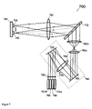
- FIG. 7 illustrates an alternate embodiment of a free-space portion of the optical wavelength switch.
- FIG. 8 a illustrates the relative position of the add-port and drop-port beams within a free-space portion of an alternate embodiment of an optical wavelength switch, relative to the input and output beams.
- FIG. 8 b illustrates resulting positions of input and output beams relative to columns of add-port and drop-port beams at a mirror array.
- FIG. 9 a illustrates one embodiment of a reflective spatially-dispersive element.
- FIG. 9 b illustrates an alternate embodiment of a transmissive spatially-dispersive element.
- FIG. 10 illustrates one embodiment of external fiber demultiplexers and multiplexers to ease the yield requirement of the free-space demultiplexers and multiplexers.
- FIG. 11 illustrates one embodiment of an apparatus to accommodate finite mirror yield by matching deflection angles of the spatially dispersive device to working mirrors.
- Coupled means coupled directly to, or indirectly through one or more intervening components.
- Coupled may mean physically and/or optically coupled as used herein.
- a line used in a figure may represent a single beam or multiple individual wavelength beams as provided herein. It should also be noted that embodiments of the present invention may be discussed herein in relation to specific frequencies, wavelengths, inputs, outputs, switches, etc., and numbers thereof, only for ease of illustration and are not so limited.
- optical switch for routing arbitrary wavelengths between optical fibers in optical networks.
- the optical switch routes wavelengths using a highly wavelength dispersive element together with a spatially dispersive element to separate the wavelengths.
- broadband switch inputs and outputs may be provided for adding and dropping arbitrary wavelengths at each node of the network.
- Fiber demultiplexers and multiplexers may also used to reduce the impact of mirror array yield on switch functionality.
- FIG. 1 illustrates one embodiment of an optical wavelength switch.
- Switch 100 is a fiber coupled wavelength switch that switches any wavelength from one or more input fibers to one or more output fibers, while allowing more than one wavelengths to be dropped to fiber-coupled drop ports 101 dd and more than one wavelengths to be added from fiber coupled add-ports 101 aa .
- the majority of the wavelength switching is performed in a free-space wavelength switch 149 .
- fiber coupled demultiplexers 151 and fiber-coupled multiplexers 161 drop and add individual wavelengths corresponding to non-working ports of free-space wavelength switch 149 .
- switch 100 has a single fiber input 150 carrying 40 wavelengths spaced in wavelength by 100 GHz on the standard ITU grid.
- Input fiber 150 is single mode fiber, for example, SMF-28 from Corning of Corning, N.Y.
- Input demultiplexer 151 separates one wavelength 141 i corresponding to a non-working wavelength of free-space optical switch 149 . The remaining 39 wavelengths are sent to free-space wavelength switch 149 by fiber 152 , or 40 wavelengths if all wavelengths of switch 149 are fully functional.
- Free-space switch 149 converts all fiber inputs 141 a , 152 , and forty add-ports 101 aa - 140 aa to free-space optical beams, and couples all output free-space beam into output optical fibers 141 d , 162 , and forty drop-ports 101 dd - 140 dd using lenses 153 and 163 and lens arrays 156 and 166 .
- Optical beams propagate in free-space if they propagate without confinement of a dielectric waveguide such as optical fiber.
- Input 152 carrying up to 40 wavelengths is converted to a free-space collimated beam by input lens 153 .
- a collimated optical beam maintains an approximately constant optical beam cross-section, except for a slow variation in cross-section due to optical diffraction.
- the effect of optical diffraction can be minimized by using sufficiently large optical beams that propagate as Gaussian beams.
- Design of optical switches using Gaussian beams is well known to those skilled in the art, for example, as described in L. Y. Lin et al., J. LightwaveTechnol., vol. 18, pp. 482-489, April 2000 and X. Zheng et al., “3D MEMS Photonic cross-connect switch design and performance”, IEEE Journal of Selected Topics in Quantum Electronics, 9(2), 571-578 (2003).
- other fibers, numbers of wavelengths, frequency spacings, ports and wavelength bands may be used.
- free-space wavelength switch 149 is configured to separate all 40 input wavelengths from fiber 150 into 40 separate optical beams 101 i - 140 i using free-space demultiplexer 154 .
- An array of 40 independent 2 ⁇ 2 free-space optical switches select whether to send input beams 101 i - 140 i to output beams 101 o - 140 o or to send any of input beams 101 i - 140 i to any of drop-port free-space beams 101 d - 140 d .
- Output beams 101 o - 140 o are combined using free-space multiplexer 164 . If any input free-space beams 101 i are propagated to any of drop-port free-space beams 101 d , the corresponding add-port beam 101 a is propagated to free-space output beam 101 o.
- two 40 ⁇ 41 cross-bar optical switches 155 and 165 are used to provide independent interconnectivity, allowing any input wavelength from input fiber 150 to be sent to any drop-port output fiber 101 dd , and allowing any wavelength from add-port input fiber 101 aa to be sent to an output wavelength on output fiber 160 .
- Using optical switches 155 and 165 allows any add-port connection to be changed without interrupting any drop-port connection, and any drop-port connection to be changed without interrupting any add-port connection.
- Any wavelength that is not operational in free-space optical switch 149 due to the yield of internal elements is routed from input fiber to output fiber using 2 ⁇ 2 fiber-coupled switch 180 .
- This input-output wavelength routing is set up by connecting fiber input 141 i to fiber output 141 o through switch 180 .
- a drop path can be set up through switch 180 , by directing input 141 i to drop port 141 a , which simultaneously connects drop path 141 d to output 141 o.
- crossbar switches 155 and/or 165 are external fiber-coupled switches, rather than free-space optical switches within free-space wavelength switch 149 .
- crossbar switches 155 and/or 165 are omitted.
- optical switch 300 can still add 40 add-port wavelengths and drop 40 drop-port wavelengths. In this case, the selection of the drop-port fiber determines which fiber the add-port wavelength is incident from. Similarly, selection of the add-port fiber determines which fiber the drop-port wavelength is directed to. If only one of crossbar switches 155 or 165 is implemented, arbitrary add-port fibers and drop-port connections still can be obtained. However, the add-port connection would be interrupted temporarily when the drop-port fiber is changed, or the drop-port connection would be interrupted temporarily when the add-port fiber is changed.
- FIG. 2 illustrates an alternative embodiment where the direct wavelength switching from input fiber 245 to output fiber 275 is provided by a fiber-coupled wavelength blocker 270 , that can pass or block any wavelength of the 40 input wavelengths from fiber 245 .
- Wavelength blockers are commercially available from manufacturers such as JDS Uniphase of Ottawa, Canada and Avanex of Fremont, Calif., USA. Most of the optical power from input fiber 245 carrying 40 wavelengths is directed to wavelength blocker 270 through optical power splitter 246 and optical fiber 247 . A smaller fraction of the optical power carrying 40 wavelengths from input fiber 245 is sent to drop fiber 250 . Wavelength blocker 270 passes the desired input wavelengths to fiber output 277 , and blocks the other wavelengths.
- optical power splitter 276 Most of the output power from fiber 277 is coupled to the output 275 carrying 40 wavelengths by optical power splitter 276 . A smaller fraction of the signals from add-fiber 260 are send to output port 275 by optical power splitter 276 .
- circulators may be used for optical power splitters 246 and 276 instead of optical power splitters, and drop-port fiber wavelengths 250 may be obtained by reflection from wavelength blocker 270 .
- Free-space switch 249 converts all fiber inputs 241 d , 252 , and forty add-ports 201 aa - 240 aa to free-space optical beams, and couples all output free-space beam into output optical fibers 241 a , 262 , and forty drop-ports 201 dd - 240 dd using lenses 253 and 263 and lens arrays 256 and 266 .
- Free-space optical switch 249 connects input wavelengths from drop-port fiber 250 to drop-port fibers 201 a - 240 a using free-space demultiplexer 254 and switch 255 , and connects add-ports 201 d - 240 d to output add-port fiber 260 using switch 265 and free-space multiplexer 264 .
- fiber coupled demultiplexers 251 and fiber-coupled multiplexers 261 drop and add individual wavelengths 241 d and 241 a corresponding to non-working ports of free-space wavelength switch 149 .
- the remaining input wavelengths and output wavelengths are directed too and from switch 249 using fibers 252 and 262 .
- two 40 ⁇ 41 cross-bar optical switches 255 and 265 that can propagate any free-space input optical beam to any free-space output optical beam are used to provide independent interconnectivity, allowing any input wavelength from drop-port fiber 250 to be sent to any drop-port output fiber 201 d - 240 d , and allows any wavelength from add-port input fibers 201 a - 240 a to be sent to an output wavelength on add-port fiber 260 .
- Fiber-coupled demultiplexer 251 drops any wavelength corresponding to a non-working wavelength of free-space switch 249 .
- Optical cross-bar switch 255 has an additional input 241 d that allows the drop-port wavelength 241 d to be send to any drop-port fiber 250 .
- Fiber-coupled multiplexer 261 allows an add-port input 201 a at a non-working wavelength of free-space switch 249 to be added to add-port fiber 260 through optical cross-bar switch 265 .
- Free-space optical switch 249 may be constructed in a similar manner to free-space optical switch 149 . However, free-space optical switch 249 is simpler than free-space optical switch 149 , as wavelength blocker 270 provides low-loss interconnect between wavelengths from input fiber 245 to output fiber 275 , easing the loss and interconnectivity requirements of free-space switch 249 compared to free-space switch 149 .
- FIG. 3 illustrates one embodiment of a free-space portion of the optical wavelength switch.
- free-space optical switch 300 may correspond to free-space optical switch 149 or free-space optical switch 249 .
- Lens array 353 collimates fiber input 352 , corresponding to fiber 152 , to form a free-space collimated input beam.
- Lens array 353 also couples an output collimated beam into output fiber 362 corresponding to output fiber 162 .
- Lens arrays fabricated from silicon wafers are available from manufacturers such as Advanced Microoptic Systems of Germany.
- mirror array 342 includes 40 micromirrors formed on a silicon substrate, each micromirror able to rotate in two axes and each directing a single input wavelength. Micromirrors of this type have been developed, for example, as discussed in Tsai, J. C. et al. “1 ⁇ N2 Wavelength-selective switches with high fill-factor two-axis analog micromirror arrays”, OFC 2004, Los Angeles, Paper MF42 (2004).
- Each micromirror 301 - 340 can direct its corresponding wavelength back through lens 381 and grating 372 to lens array 353 and output fiber 362 .
- each mirror of array 342 can direct an input wavelength to a drop port, by steering the beam to folding prism 371 .
- the diameter of each drop-port free-space optical beam is reduced by reverse propagation through a beam expander comprising an array of lenses 382 a and an array of lenses 382 b .
- the Gaussian beam parameters of the free-space optical beams can be chosen such that the second array of lenses 382 b is not needed in order to adjust the free-space optical beam diameter.
- Each wavelength that is directed to a drop port is first steered by mirror array 342 to one of four drop-port positions 401 d - 404 d shown in FIG. 4 a .
- the position of the free-space add-port beams 401 a - 404 a and drop-port beams 401 d - 404 d are shown relative to the folding prism 471 corresponding to folding prism 371 of FIG. 3 .
- the add-ports and drop ports reflect around the prism vertex 474 corresponding to vertex 374 , to form another set of add-port positions 411 a - 414 a and drop-port positions 411 d - 414 d.
- Ten wavelengths having every fourth wavelength including wavelengths 1 , 5 , 9 , and higher are sent to drop-port position 401 d .
- the next set of ten wavelengths including wavelengths 2 , 6 , 10 , and higher are sent to position 402 d .
- the next set of ten wavelengths are sent to position 403 d
- the final set of ten wavelengths are sent to position 404 d .
- mirror array 342 acts as a wavelength interleaver for drop-port wavelengths, and each drop-port position has up to 10 wavelengths at 400 GHz wavelength spacing.
- the drop-port optical beams pass through dispersive grating 372 a second time, to lens array 383 , and then to spatially dispersive element 373 .
- Spatially dispersive element 373 has ten facets that increase the angular dispersion from the ten wavelengths in each drop-port position 401 d - 404 d .
- the facets on spatially dispersive element 373 producing discontinuous changes in optical beam angle as a function of optical beam position.
- Each wavelength reflects back from spatially dispersive element 373 and passes back through lens array 383 at a different angle, arriving at grating 372 at a different position.
- switch 300 is illustrated with a single grating 372 through which optical signals pass through different times at different positions, in an alternative embodiment, grating 372 (and the other gratings discussed below) may be composed of two or more distinct grating elements.
- Each drop port beam, now carrying a single wavelength, is incident on mirror array 365 containing 40 mirrors for the 40 drop-port wavelengths, where each mirror in array 365 is able to rotate in two axes.
- Mirror array 355 also contains 40 mirrors for the drop-port wavelengths.
- Mirror arrays 355 and 365 together with lens 384 form a nonblocking optical cross-connect switch 360 , allowing any drop-port wavelength to be connected to any of 40 drop-port fibers 301 d - 340 d , although only one drop port 301 d is shown for clarity.
- Lens array 356 couples the free-space collimated drop-port beams into drop-port fibers 301 d - 340 d .
- Lens array 384 counteracts Gaussian beam diffraction through the switch, and reduces optical clipping loss by reducing the optical beam size at each mirror of mirror arrays 355 and 365 .
- the spatial separation of wavelengths from drop-port beams may be performed by arrays of interference filters, rather than by grating 372 and spatially dispersive element 373 .
- Interference filters pass a band of wavelengths, and reflect the other wavelengths. Interference filters are commercially available from manufacturers such as AOC of Pleasanton, Calif.
- there would be an additional beam expander between grating 372 and mirror array 365 in order to change the size of the beams from the beam size leaving grating 372 to the beam size at mirror array 365 .
- mirror arrays 355 and 365 may be replaced by a single larger mirror array containing both input and output mirrors, and lens 384 may be replaced by a curved fixed mirror to form a reflective optical switch.
- the 40 add-port optical fibers 301 a - 340 a are connected to optical switch 300 in the same way as the drop-port optical fibers 301 d - 340 d , although only one add-port optical fiber 301 a is shown for clarity.
- Lens array 356 collimates fiber inputs 301 a - 340 a to form free-space collimated input beams.
- Mirror arrays 355 and 365 each contain an additional 40 mirrors for switching any add-port fiber to any add-port wavelength.
- the add-port collimated beams pass from mirror array 365 through lens array 383 to spatially dispersive element 373 .
- Fixed mirror 375 routes signals 141 a and 141 d to the opposite sides of switches 155 and 165 of FIG. 1 , to allow bypassing a non-working wavelength of wavelength switch 300 .
- Fixed mirror 375 allows an add-port (not shown) corresponding to add-port 141 a of FIG. 1 to connect to any drop point 301 d - 340 d , and allows any add-port 301 a - 340 a to connect to a drop port (not shown) corresponding to drop port 141 d of FIG. 1 .
- the add-port beams reflect off of spatially dispersive element 373 , through lens array 383 to grating 372 , then to lens arrays 382 b and 382 a that act as beam expanders when propagating in this direction.
- Prism 371 folds the add-port optical beams, and directs them to grating 372 .
- the add-port optical beams pass through lens 381 to mirror array 342 .
- the add-port beams reflect off of mirror array 342 , and can be steered back through lens 381 to grating 372 by mirrors 301 - 340 , and over folding prism 371 to output fiber 362 .
- Lens array 353 couples the free-space optical beam containing up to 40 wavelengths to output fiber 362 .
- FIG. 4 b The use of a single mirror to steer the input beam to a drop port and simultaneously steer an add-port to an output beam is illustrated in FIG. 4 b .
- This simultaneous switching can be achieved with a single mirror by precise positioning of the add-port free-space beams relative to the drop-port free-space beams.
- Two of the add-port beams 423 a and 424 a corresponding to add-port beams 403 a and 404 a are shown relative to prism 473 corresponding to prism 471 .
- two of the drop-port beams 423 d and 424 d corresponding to drop-port beams 403 d and 404 d are shown.
- a wavelength in input beam 453 corresponding to input beam 452 is connected to drop-port position 424 d .
- This mirror position simultaneously connects a wavelength from add-port 424 a to output port 463 as illustrated in FIG. 4 b with the solid arrows showing the interconnection of ports.
- a wavelength in input beam 453 corresponding to input beam 452 is connected to drop-port 423 d .
- This mirror position simultaneously connects a wavelength from add-port 423 a to output port 463 .
- a wavelength in input beam 453 corresponding to input beam 452 is connected to output beam 463 corresponding to output beam 462 .
- FIG. 5 illustrates one embodiment of a dispersive grating device used to convert the wavelength separation of optical beams 552 into angular separation of optical output beams 581 .
- the dispersive grating element 500 corresponds to grating 372 .
- a grating 573 is placed in the middle of a prism 570 .
- the combination of grating 573 and prism 570 produces a larger angular dispersion than a grating along.
- This type of grating-prism structure is available from manufacturers such as Wasatch of Logan, Utah and Kaiser Optical Systems of Ann Arbor, Mich.
- FIG. 6 illustrates one embodiment of a lens array and reflective prism used to spatially separate the different wavelengths from input beams 652 to output beams 662 .
- lens array 683 corresponding to lens array 383 has four elements, corresponding to the four rows of add-port and drop-port optical beams.
- Spatially dispersive element 673 corresponding to spatially dispersion element 373 has ten reflective surfaces, of which four are shown, and is made by a process similar to diamond-turning diffraction gratings.
- FIG. 7 An alternative embodiment 700 of free-space wavelength switch 149 or 249 is shown in FIG. 7 .
- Input fiber 752 and output fiber 762 correspond to input fiber 352 and output fiber 362 , and each carry 40 wavelengths.
- Lens array 753 produces collimated beams from input fiber 753 and from up to 40 add-port fibers 701 a - 740 a , although only one add-port fiber 701 a is shown for clarity.
- Lens array 753 also couples the output beam into fiber 762 and up to 40 output wavelengths into 40 drop fibers 701 d - 740 d , although only one drop-port fiber 701 d is shown for clarity.
- Two-dimensional arrays of mirror 755 and 765 together with lens 784 form a cross-connect switch 760 for free-space optical beams to allow any input wavelength to switch to any drop fiber 701 d - 740 d , and any add-port fiber 701 a - 740 a to connect to the output fiber 762 .
- Fixed mirror 775 routes signals 141 a and 141 d to the opposite sides of switches 155 and 165 of FIG. 1 , to allow bypassing a non-working wavelength of wavelength switch 300 .
- Cross-connect switch 760 may also be used to correct mechanical drift of beam angle and position changes over temperature.
- mirror arrays 755 and 765 are replaced by a single larger mirror array with input and output mirrors, and lens 784 is replaced by a curved fixed mirror to form a reflective optical switch configuration.
- the input beam from fiber 752 passes through beam expander comprising lenses 782 a and 782 b in order to expand the free-space input beam from small optical beams in switch 760 to a larger optical beams incident on grating 772 .
- Grating 772 separates different wavelengths of the input beam in angle.
- Lens 781 focuses each wavelength to a different mirror of mirror array 742 .
- Mirror array 742 includes a linear array of 40 mirrors 701 - 740 , with each mirror rotating in two axes. Each mirror 701 - 740 can steer a particular wavelength back through lens 781 , grating 772 , and beam expander 782 b - 782 a to the output fiber 762 or to a drop-port fiber 701 d - 740 d.
- free-space switch 700 is simpler than free-space switch 300 , as the second pass through grating 372 and spatially dispersive element 373 is eliminated.
- the distance from grating 772 to mirror array 742 is significantly longer than the distance from grating 372 to mirror array 342 in order to achieve the required switching.
- This increased distance in free-space switch 700 decreases the alignment tolerance and other optical tolerances for achieving low optical loss from the input fiber to the output fiber.
- the mirrors corresponding to the input fiber 752 and output fiber 762 are larger than the mirror corresponding to add-ports and drop-ports, which have higher rotation angle requirements.
- the position of the free-space optical beams of the add-ports and drop-ports at mirror array 765 relative to the input and output port is shown in FIG. 8 a .
- the input port 852 corresponding to the beam from input fiber 752 is surrounded in the illustration by five columns of add-port beams 801 a
- the output port beam 862 is surrounded in the illustration by five columns of drop-port beams 801 d .
- the input beam and output beam may be surrounded by at least 40 add-port beams or drop-port beams.
- the positions of the input port beam and output port beam at mirror array 755 are chosen to minimize the required deflection angle of the input port mirror and output port mirror in mirror array 765 .
- the optimum positions of the input and output beams are near the center of mirror array 755 .
- the resulting positions of the input beam 853 and output beam 863 relative to five columns of add-port beams 802 a and five columns of drop-port beams 802 d at mirror array 755 are illustrated in FIG. 8 b.
- FIG. 9 a illustrates an alternate embodiment spatially dispersive element 973 corresponding to reflective spatially dispersive element 373 of FIG. 3 .
- spatially dispersive element 973 includes of number of reflective prisms equal to the number of input wavelengths, each prism using its angled surface to reflect the output beam at a given wavelength to a desired angle.
- Inputs 901 and 903 diverge in angle due to wavelength dispersive grating 372 of FIG. 3 .
- Spatially dispersive element 973 increases the divergence between output beams 911 and 913 by reflecting these beams at different angles.
- the prism faces of spatially dispersive elements 373 and 973 can be formed, for example, by diamond turning multiple faces on a cylinder blank, or other known means of fabricating multiple reflective surfaces.
- the prism faces can formed, for example, by selective etching of the substrate, followed by high temperature mass transport to smooth the prism surface.
- the mass transport method is well known in the art for fabrication of arbitrary lens shapes, and a prism is a special case of a lens.
- the prisms may also be formed, for example, by gray-scale lithography of photoresist material, then transferring the resulting prism from the photoresist to the semiconductor substrate by etching, or other known methods.
- dispersive elements 373 and 973 may be formed by etching mirrors in silicon, with mirrors latching in angle so that each mirror is permanently set to a predetermined angle.
- FIG. 9 b illustrates a transmissive spatially dispersive element 974 corresponding to reflective spatially dispersive element 373 of FIG. 3 .
- spatially dispersive element 974 includes of a number of prisms equal to the number of input wavelengths, each prism face using its angled surface to refract the output beam at a given wavelength to a desired angle.
- the divergence of input optical beams 921 - 925 is increased by spatially dispersive element 974 to produce output optical beams 931 - 935 with higher divergence angles.
- One difficulty in fabricating prior art wavelength-selective optical switches is that they require 100% mirror yield within the array, and any mirror yield fallout produces wavelength blocking.
- One embodiment of the present invention that reduces the impact of mirror yield involves dividing the input wavelengths 1050 into subbands external to the free-space switch 1049 as illustrated in FIG. 10 . This results in multiple free-space demultiplexers 1054 and 1055 having fewer output wavelengths that reduces the sensitivity to mirror yield. In one embodiment, four demultiplexers 1054 need ten working mirrors in a set, rather than 40 working mirrors required if a subband approach was not used.
- demultiplexer 1051 is a wavelength interleaver, which separates 40 wavelengths separated by 100 GHz to two fibers each carrying 20 wavelengths separated by 200 GHz.
- Finite yield of mirror array 365 of FIG. 3 also can be accommodated by appropriate design of spatially dispersive element 373 of FIG. 3 .
- This method of accommodating finite mirror yield is illustrated in FIG. 11 using a transmissive spatially dispersive element corresponding to 974 of FIG. 9 b.
- FIG. 11 illustrates one embodiment of an apparatus to accommodate finite mirror yield by matching deflection angles of the spatially dispersive device to working mirrors.
- spatially dispersive element 1174 is custom fabricated to match the measured mirror yield of mirror array 1155 .
- Spatially dispersive element 1174 directs optical beam 1103 to working mirror 1152 rather than nonworking mirror 1151 .
- the fibers, numbers of wavelengths, frequency spacings, ports, wavelength bands, etc. provided herein are only exemplary and the present invention is not intended to be limited thereto.
Abstract
Description
Claims (12)
Priority Applications (1)
| Application Number | Priority Date | Filing Date | Title |
|---|---|---|---|
| US11/824,904 US7529441B2 (en) | 2003-06-30 | 2007-07-02 | Wavelength routing optical switch |
Applications Claiming Priority (3)
| Application Number | Priority Date | Filing Date | Title |
|---|---|---|---|
| US48411203P | 2003-06-30 | 2003-06-30 | |
| US10/879,639 US7254293B1 (en) | 2003-06-30 | 2004-06-28 | Wavelength routing optical switch |
| US11/824,904 US7529441B2 (en) | 2003-06-30 | 2007-07-02 | Wavelength routing optical switch |
Related Parent Applications (1)
| Application Number | Title | Priority Date | Filing Date |
|---|---|---|---|
| US10/879,639 Division US7254293B1 (en) | 2003-06-30 | 2004-06-28 | Wavelength routing optical switch |
Publications (2)
| Publication Number | Publication Date |
|---|---|
| US20070258679A1 US20070258679A1 (en) | 2007-11-08 |
| US7529441B2 true US7529441B2 (en) | 2009-05-05 |
Family
ID=38324407
Family Applications (2)
| Application Number | Title | Priority Date | Filing Date |
|---|---|---|---|
| US10/879,639 Active 2024-12-01 US7254293B1 (en) | 2003-06-30 | 2004-06-28 | Wavelength routing optical switch |
| US11/824,904 Active US7529441B2 (en) | 2003-06-30 | 2007-07-02 | Wavelength routing optical switch |
Family Applications Before (1)
| Application Number | Title | Priority Date | Filing Date |
|---|---|---|---|
| US10/879,639 Active 2024-12-01 US7254293B1 (en) | 2003-06-30 | 2004-06-28 | Wavelength routing optical switch |
Country Status (1)
| Country | Link |
|---|---|
| US (2) | US7254293B1 (en) |
Cited By (2)
| Publication number | Priority date | Publication date | Assignee | Title |
|---|---|---|---|---|
| US20100221004A1 (en) * | 2009-02-27 | 2010-09-02 | Thomas Haslam | Method for auto-configuration of a wavelength selective switch in an optical network |
| US8639069B1 (en) | 2003-06-30 | 2014-01-28 | Calient Technologies, Inc. | Wavelength dependent optical switch |
Families Citing this family (8)
| Publication number | Priority date | Publication date | Assignee | Title |
|---|---|---|---|---|
| JP4530821B2 (en) * | 2004-08-16 | 2010-08-25 | 富士通株式会社 | Optical add / drop device |
| US7573918B1 (en) * | 2006-08-07 | 2009-08-11 | Calmar Optcom, Inc. | Dispersion compensated mode-locked pulsed lasers and optical amplifiers |
| US7702194B2 (en) * | 2006-11-07 | 2010-04-20 | Olympus Corporation | Beam steering element and associated methods for manifold fiberoptic switches |
| WO2011048599A1 (en) * | 2009-10-22 | 2011-04-28 | Yissum Research Development Company Of The Hebrew University Of Jerusalem Ltd. | Method and system for switching optical channels |
| US20180017735A1 (en) * | 2016-07-13 | 2018-01-18 | Futurewei Technologies, Inc. | Wavelength Division Multiplexer/Demultiplexer with Flexibility of Optical Adjustment |
| EP3291000B1 (en) * | 2016-08-30 | 2020-12-16 | Accelink Technologies Co., Ltd. | Wavelength selective switch |
| US10715270B2 (en) | 2016-10-25 | 2020-07-14 | Nec Corporation | Optical branching/coupling device and optical branching/coupling method |
| US11733468B2 (en) * | 2021-12-08 | 2023-08-22 | Viavi Solutions Inc. | Photonic structure using optical heater |
Citations (16)
| Publication number | Priority date | Publication date | Assignee | Title |
|---|---|---|---|---|
| US4244045A (en) | 1978-01-31 | 1981-01-06 | Nippon Telegraph And Telephone Public Corporation | Optical multiplexer and demultiplexer |
| US5859717A (en) | 1997-02-14 | 1999-01-12 | Corning Oca Corporation | Multiplexing device with precision optical block |
| US5960133A (en) | 1998-01-27 | 1999-09-28 | Tellium, Inc. | Wavelength-selective optical add/drop using tilting micro-mirrors |
| US6097859A (en) | 1998-02-12 | 2000-08-01 | The Regents Of The University Of California | Multi-wavelength cross-connect optical switch |
| WO2001057902A2 (en) | 2000-02-03 | 2001-08-09 | Calient Networks, Inc. | Electrostatic actuator for microelectromechanical systems and methods of fabrication |
| US6285500B1 (en) | 1999-06-29 | 2001-09-04 | Corning Incorporated | Wavelength selective switch |
| US6501877B1 (en) | 1999-11-16 | 2002-12-31 | Network Photonics, Inc. | Wavelength router |
| US20030031406A1 (en) | 2001-08-08 | 2003-02-13 | Takashi Saida | Optical filter |
| US6549699B2 (en) | 2001-03-19 | 2003-04-15 | Capella Photonics, Inc. | Reconfigurable all-optical multiplexers with simultaneous add-drop capability |
| US20030215179A1 (en) | 2001-03-30 | 2003-11-20 | Mcguire James P. | Programmable optical add/drop multiplexer |
| US20040067014A1 (en) | 2002-10-04 | 2004-04-08 | Hollars Dennis R. | Miniature optical multiplexer/de-multiplexer DWDM device, and method of aligning components thereof |
| US6750995B2 (en) | 2001-07-09 | 2004-06-15 | Dickson Leroy David | Enhanced volume phase grating with high dispersion, high diffraction efficiency and low polarization sensitivity |
| US20050063641A1 (en) | 2001-06-29 | 2005-03-24 | Neilson David Thomas | Imaging technique for use with optical mems devices |
| US7058253B1 (en) * | 2002-08-13 | 2006-06-06 | Novotny Vlad J | Integrated fiber, sensor and lens arrays and their applications for optical networks |
| US7072539B2 (en) | 2002-08-08 | 2006-07-04 | The Regents Of The University Of California | Wavelength-selective 1×N2 switches with two-dimensional input/output fiber arrays |
| US7088882B2 (en) | 2002-05-20 | 2006-08-08 | Metconnex Canada, Inc. | Wavelength cross-connect |
-
2004
- 2004-06-28 US US10/879,639 patent/US7254293B1/en active Active
-
2007
- 2007-07-02 US US11/824,904 patent/US7529441B2/en active Active
Patent Citations (17)
| Publication number | Priority date | Publication date | Assignee | Title |
|---|---|---|---|---|
| US4244045A (en) | 1978-01-31 | 1981-01-06 | Nippon Telegraph And Telephone Public Corporation | Optical multiplexer and demultiplexer |
| US6389190B2 (en) | 1997-02-13 | 2002-05-14 | The Regents Of The University Of California | Multi-wavelength cross-connect optical switch |
| US5859717A (en) | 1997-02-14 | 1999-01-12 | Corning Oca Corporation | Multiplexing device with precision optical block |
| US5960133A (en) | 1998-01-27 | 1999-09-28 | Tellium, Inc. | Wavelength-selective optical add/drop using tilting micro-mirrors |
| US6097859A (en) | 1998-02-12 | 2000-08-01 | The Regents Of The University Of California | Multi-wavelength cross-connect optical switch |
| US6285500B1 (en) | 1999-06-29 | 2001-09-04 | Corning Incorporated | Wavelength selective switch |
| US6501877B1 (en) | 1999-11-16 | 2002-12-31 | Network Photonics, Inc. | Wavelength router |
| WO2001057902A2 (en) | 2000-02-03 | 2001-08-09 | Calient Networks, Inc. | Electrostatic actuator for microelectromechanical systems and methods of fabrication |
| US6549699B2 (en) | 2001-03-19 | 2003-04-15 | Capella Photonics, Inc. | Reconfigurable all-optical multiplexers with simultaneous add-drop capability |
| US20030215179A1 (en) | 2001-03-30 | 2003-11-20 | Mcguire James P. | Programmable optical add/drop multiplexer |
| US20050063641A1 (en) | 2001-06-29 | 2005-03-24 | Neilson David Thomas | Imaging technique for use with optical mems devices |
| US6750995B2 (en) | 2001-07-09 | 2004-06-15 | Dickson Leroy David | Enhanced volume phase grating with high dispersion, high diffraction efficiency and low polarization sensitivity |
| US20030031406A1 (en) | 2001-08-08 | 2003-02-13 | Takashi Saida | Optical filter |
| US7088882B2 (en) | 2002-05-20 | 2006-08-08 | Metconnex Canada, Inc. | Wavelength cross-connect |
| US7072539B2 (en) | 2002-08-08 | 2006-07-04 | The Regents Of The University Of California | Wavelength-selective 1×N2 switches with two-dimensional input/output fiber arrays |
| US7058253B1 (en) * | 2002-08-13 | 2006-06-06 | Novotny Vlad J | Integrated fiber, sensor and lens arrays and their applications for optical networks |
| US20040067014A1 (en) | 2002-10-04 | 2004-04-08 | Hollars Dennis R. | Miniature optical multiplexer/de-multiplexer DWDM device, and method of aligning components thereof |
Non-Patent Citations (8)
| Title |
|---|
| D.M. Marom, D.M. et al., "Wavelength-selective 1x4 switch for 128 WDM channels at 50 GHz spacing," OFC 2002 PostDeadline papers, FB7-1, (2002). |
| J.I. Dadap et al. "Modular MEMS-Based Optical Cross-Connect With Large Port-Count", IEEE Photonics Technology Letters, vol. 15, No. 12, Dec. 2003, pp. 1773-1775. |
| Jay S. Patel and Yaron Silberberg, "Liquid Crystal and Grating-Based Multiple-Wavelength Cross-Connect Switch", IEEE Photonics Technology Letters, vol. 7, No. 5, pp. 514-516 (May 1995). |
| Lin, L.Y. et al., "On the expandability of free-space micromachined optical cross connects," J. Lightwave Technol., vol. 18, pp. 482-489, Apr. 2000. |
| Suzuki, S. et al., "Integrated Multichannel Optical Wavelength Selective Switchse Incorporating an Arrayed-Waveguide Grating Multiplexer and Thermooptic Switches," J. of Lightware Technology, 16(4), pp. 650-655 (Apr. 1998). |
| Tsai, J.C. et al. "1xN2 Wavelength-selective switches with high fill-factor two axis analog micromirror arrays", OFC 2004, Los Angeles, Paper MF42 (2004). nttp://www.Photonics.ucla.edu/pdf/IPL-UCLA-JCTsai-OFC-2004-idl55.pdf. |
| Tsai, J.C. et al., "Open-Loop Operation of MEMS-Based 1xNWavelength-Selective Switch With Long-Term Stability and Repeatability" IEEE Photonics Technology Letters, 16(4), pp. 1041-1043 (Apr. 2004). http://www.photonics.ucla.edu/pdf/IPL-UCLA-JCTsai-PhotonicsTechnologyLetters-2004-id157.pdf. |
| Zheng, X. et al., "Three-Dimensional MEMS Photonic cross-connect switch design and performance", IEEE Journal of Selected Topics in Quantum Electronics, 9(2), 571-578 (Mar./Apr. 2003). |
Cited By (4)
| Publication number | Priority date | Publication date | Assignee | Title |
|---|---|---|---|---|
| US8639069B1 (en) | 2003-06-30 | 2014-01-28 | Calient Technologies, Inc. | Wavelength dependent optical switch |
| US20100221004A1 (en) * | 2009-02-27 | 2010-09-02 | Thomas Haslam | Method for auto-configuration of a wavelength selective switch in an optical network |
| US8948592B2 (en) * | 2009-02-27 | 2015-02-03 | Jds Uniphase Corporation | Method for auto-configuration of a wavelength selective switch in an optical network |
| US9706273B2 (en) | 2009-02-27 | 2017-07-11 | Lumentum Operations Llc | Method for auto-configuration of a wavelength selective switch in an optical network |
Also Published As
| Publication number | Publication date |
|---|---|
| US7254293B1 (en) | 2007-08-07 |
| US20070258679A1 (en) | 2007-11-08 |
Similar Documents
| Publication | Publication Date | Title |
|---|---|---|
| US7529441B2 (en) | Wavelength routing optical switch | |
| USRE47906E1 (en) | Reconfigurable optical add-drop multiplexers with servo control and dynamic spectral power management capabilities | |
| USRE42521E1 (en) | Reconfigurable optical add-drop multiplexers employing polarization diversity | |
| US6549699B2 (en) | Reconfigurable all-optical multiplexers with simultaneous add-drop capability | |
| US6826349B2 (en) | Wavelength router | |
| JP4043693B2 (en) | Optical device | |
| US6631222B1 (en) | Reconfigurable optical switch | |
| AU2002255773B2 (en) | Reconfigurable optical add-drop multiplexers | |
| US20030035168A1 (en) | Spectrum division multiplexing for high channel count optical networks | |
| US20070041683A1 (en) | Tunable Optical Filter | |
| US6449407B1 (en) | Optical switch having equalized beam spreading in all connections | |
| US6956987B2 (en) | Planar lightwave wavelength blocker devices using micromachines | |
| US8639069B1 (en) | Wavelength dependent optical switch | |
| WO2017088115A1 (en) | Reconfigurable optical add-drop multiplexer | |
| JP5651904B2 (en) | N × N wavelength selective switch | |
| WO2019203307A1 (en) | Wavelength-selective optical switch | |
| CN117031636B (en) | Wavelength selective switch with Tain structure and intelligent optical network device | |
| US6950571B1 (en) | Optical switchable component | |
| Chi et al. | Silicon-based monolithic 4× 4 wavelength-selective cross connect with on-chip micromirrors |
Legal Events
| Date | Code | Title | Description |
|---|---|---|---|
| STCF | Information on status: patent grant |
Free format text: PATENTED CASE |
|
| FPAY | Fee payment |
Year of fee payment: 4 |
|
| AS | Assignment |
Owner name: CALIENT NETWORKS, INC., CALIFORNIA Free format text: ASSIGNMENT OF ASSIGNORS INTEREST;ASSIGNORS:HELKEY, ROGER JONATHAN;YUAN, SHIFU;ZHENG, XUEZHE;SIGNING DATES FROM 20040726 TO 20040727;REEL/FRAME:030035/0906 |
|
| AS | Assignment |
Owner name: CALIENT TECHNOLOGIES, INC., CALIFORNIA Free format text: CHANGE OF NAME;ASSIGNOR:RIVIERA SYSTEMS, INC.;REEL/FRAME:030077/0566 Effective date: 20100916 Owner name: RIVIERA SYSTEMS, INC., CALIFORNIA Free format text: CHANGE OF NAME;ASSIGNOR:CALIENT NETWORKS, INC.;REEL/FRAME:030126/0257 Effective date: 20100916 |
|
| FEPP | Fee payment procedure |
Free format text: PAT HOLDER CLAIMS SMALL ENTITY STATUS, ENTITY STATUS SET TO SMALL (ORIGINAL EVENT CODE: LTOS); ENTITY STATUS OF PATENT OWNER: SMALL ENTITY Free format text: PAYOR NUMBER ASSIGNED (ORIGINAL EVENT CODE: ASPN); ENTITY STATUS OF PATENT OWNER: SMALL ENTITY Free format text: PAYER NUMBER DE-ASSIGNED (ORIGINAL EVENT CODE: RMPN); ENTITY STATUS OF PATENT OWNER: SMALL ENTITY |
|
| AS | Assignment |
Owner name: SILICON VALLEY BANK, CALIFORNIA Free format text: SECURITY INTEREST;ASSIGNOR:CALIENT TECHNOLOGIES, INC.;REEL/FRAME:040503/0218 Effective date: 20160826 |
|
| REMI | Maintenance fee reminder mailed | ||
| FPAY | Fee payment |
Year of fee payment: 8 |
|
| SULP | Surcharge for late payment |
Year of fee payment: 7 |
|
| AS | Assignment |
Owner name: CALIENT HOLDINGS, LLC, CALIFORNIA Free format text: SECURITY INTEREST;ASSIGNOR:CALIENT TECHNOLOGIES, INC.;REEL/FRAME:044914/0972 Effective date: 20171215 |
|
| AS | Assignment |
Owner name: CALIENT TECHNOLOGIES, INC., CALIFORNIA Free format text: RELEASE BY SECURED PARTY;ASSIGNOR:SILICON VALLEY BANK;REEL/FRAME:052921/0551 Effective date: 20200611 |
|
| AS | Assignment |
Owner name: CALIENT TECHNOLOGIES, INC., CALIFORNIA Free format text: RELEASE BY SECURED PARTY;ASSIGNOR:CALIENT HOLDINGS, LLC;REEL/FRAME:053251/0224 Effective date: 20200720 |
|
| MAFP | Maintenance fee payment |
Free format text: PAYMENT OF MAINTENANCE FEE, 12TH YR, SMALL ENTITY (ORIGINAL EVENT CODE: M2553); ENTITY STATUS OF PATENT OWNER: SMALL ENTITY Year of fee payment: 12 |