US7537171B2 - Thermostat control system providing power saving transmissions - Google Patents
Thermostat control system providing power saving transmissions Download PDFInfo
- Publication number
- US7537171B2 US7537171B2 US10/990,897 US99089704A US7537171B2 US 7537171 B2 US7537171 B2 US 7537171B2 US 99089704 A US99089704 A US 99089704A US 7537171 B2 US7537171 B2 US 7537171B2
- Authority
- US
- United States
- Prior art keywords
- signals
- remote
- control system
- power level
- thermostat
- Prior art date
- Legal status (The legal status is an assumption and is not a legal conclusion. Google has not performed a legal analysis and makes no representation as to the accuracy of the status listed.)
- Active, expires
Links
Images


Classifications
-
- G—PHYSICS
- G05—CONTROLLING; REGULATING
- G05D—SYSTEMS FOR CONTROLLING OR REGULATING NON-ELECTRIC VARIABLES
- G05D23/00—Control of temperature
- G05D23/19—Control of temperature characterised by the use of electric means
- G05D23/1902—Control of temperature characterised by the use of electric means characterised by the use of a variable reference value
- G05D23/1905—Control of temperature characterised by the use of electric means characterised by the use of a variable reference value associated with tele control
-
- F—MECHANICAL ENGINEERING; LIGHTING; HEATING; WEAPONS; BLASTING
- F23—COMBUSTION APPARATUS; COMBUSTION PROCESSES
- F23N—REGULATING OR CONTROLLING COMBUSTION
- F23N5/00—Systems for controlling combustion
- F23N5/20—Systems for controlling combustion with a time programme acting through electrical means, e.g. using time-delay relays
- F23N5/203—Systems for controlling combustion with a time programme acting through electrical means, e.g. using time-delay relays using electronic means
-
- F—MECHANICAL ENGINEERING; LIGHTING; HEATING; WEAPONS; BLASTING
- F23—COMBUSTION APPARATUS; COMBUSTION PROCESSES
- F23N—REGULATING OR CONTROLLING COMBUSTION
- F23N2223/00—Signal processing; Details thereof
- F23N2223/38—Remote control
Definitions
- the present invention relates generally to climate control systems, and more particularly to a thermostat control system for controlling transmission power between thermostat control system devices, including remote units.
- Thermostat control systems typically include a thermostat unit for sensing climate conditions (e.g., temperature) and controlling an associated Heating Ventilating and Air Conditioning (HVAC) system.
- HVAC Heating Ventilating and Air Conditioning
- Multiple thermostat units may be provided with each controlling a separate climate zone using a single HVAC system or separate HVAC systems.
- a separate thermostat unit may be provided on each floor of a home for separately controlling (i.e., monitoring and activating) the heating and cooling on each floor (usually, but not necessarily) using separate heating and air conditioning units.
- thermostat units Even with multiple thermostat units or separate climate zones, maintaining a comfortable temperature level in different portions of a building during different times of day is very difficult.
- a programmable thermostat unit may be used to provide additional climate control (e.g., different set point temperatures during different time periods).
- additional climate control e.g., different set point temperatures during different time periods.
- the thermostat unit is installed in a location (e.g., kitchen hallway) that is not desirable for temperature measurements relative to other rooms in a building (e.g., a house). Also, individuals in a house usually occupy different rooms at different times of the day. Thus, the thermostat unit fails to accommodate the climate control needs of occupants at various times of the day. Further, outdoor conditions, including for example, the angle of the sun, may affect internal house temperature in different rooms. This further increases the problem of maintaining comfortable climate levels in different rooms of a house throughout the day.
- thermostat unit may be programmed to use the transmitted sensed temperature information from the sensor in that particular room to activate cooling and/or heating.
- the thermostat unit may be configured for processing sensed transmitted climate conditions from more than one remote sensor to thereby control an HVAC system to heat and/or cool a building.
- a thermostat unit is the 1F95-479 model thermostat, manufactured and sold by the White-Rodgers Division of Emerson Electric Co.
- Remote sensors are usually more desirable than wired sensors because of the ease of installation (i.e., no hard wiring required).
- remote sensors are typically powered by replaceable internal power supplies (e.g., batteries), making power conservation (i.e., reducing power consumption and usage) a larger concern.
- conserveing power is also a concern in battery powered thermostat units. For example, if a climate control system is replaced, with the associated thermostat unit also replaced, additional sources of power (e.g., an internal power supply) for the thermostat unit may be required to control the new system, such as when replacing a single stage system with a multi-stage system.
- Systems and devices are known that attempt to conserve or save power in order to extend the life of the replaceable power supplies within specific devices of a thermostat control system. Some of these systems transmit only at lower power levels, which may result in a failure to provide reliable transmissions depending upon the distance between the thermostat unit and sensors, as well as other interference.
- the number of transmissions from a remote sensor may be reduced, for example, by transmitting temperature information only after a predetermined time period. Although this may conserve power, unnecessary transmissions can occur during extended periods in which temperature variations do not exceed a fraction of a degree in temperature. For example, if the temperature in a house remains relatively constant at 70 degrees for a two hour period, a sensor that transmits on a periodic basis would waste power transmitting the same temperature value to the thermostat, which would accordingly hold the heating and cooling systems in an off state.
- Still other systems include devices having different types of low-power transmitters, which are typically costly, and again may fail to provide reliable transmissions.
- multiple sensors or transmitting units may be required to transmit sensed temperature information from the remote sensing unit to the main thermostat unit located a distance from the remote sensor (i.e., transmit from one unit to the next).
- the present invention provides a low-cost system and method for reducing power consumption in climate control systems having remote and/or other internally powered components, while maintaining reliability in transmissions.
- transmissions are provided at one of two power levels, with climate control data or information transmitted at one of two different data transfer rates (i.e., data transmission speeds).
- a transmitting device e.g. a transmitter or transceiver
- corresponding receiving device e.g., receiver or transceiver
- a thermostat control system is provided that transmits and receives climate information preferably using radio frequency (RF) signals at the different power levels and data transfer rates.
- the transmitter and receiver may be provided separately in different system components.
- a transmitter constructed according to the present invention may be provided in a remote sensor, with a receiver constructed according to the present invention adapted to receive transmissions from the transmitter provided in a thermostat unit, or vice versa.
- a transmitter and receiver may be provided in both the thermostat unit and each remote sensor, and may be implemented either as separate component parts or as a single unit (e.g., a transceiver).
- a transceiver allows for bidirectional communication between the thermostat unit and the remote sensors.
- a transmitting device of the present invention within, for example, a thermostat unit or remote sensor powered by an internal replaceable power supply (e.g., batteries), preferably transmits a lower power signal more frequently than a higher power signal.
- the remote sensor may transmit multiple times at the lower power level followed by a single higher power level transmission.
- a higher power level transmission may occur at a predetermined time interval to ensure that a corresponding receiving device receives at least this higher power transmission (e.g., every thirty minutes if no higher power level transmission occurs).
- the periodic higher power transmissions ensure that, for example, the thermostat unit receives climate control information at least once during a predetermined time period. Reliability of climate information is thereby maintained during normal operation of the thermostat control system.
- the higher power level transmission is preferably provided at a lower data transfer rate and the lower power transmission is preferably provided at higher data transfer rate.
- a transmitting device of the present invention may be configured to transmit only at a higher power level. This provides the user with time to select a new location for the transmitting device while maintaining reliable transmissions until a new location is selected.
- a setup or learn mode and a normal operating mode are preferably provided.
- remote sensors may be adjusted (i.e., relocated) depending upon the thermostat unit requirements. For example, the placement of remote sensor units may be changed to maximize or optimize transmission signal reception strength (ensure low power level transmissions are received).
- the signal reception strength may be displayed on the thermostat unit as a signal strength indicator for each remote sensor.
- Each sensor comprises a device serial number unique to the particular sensor.
- each sensor is prompted to transmit a “flag” within the transmission signal that provides a unique identification of the serial number of the sensor, which is used by the thermostat's transceiver unit later to recognize a signal from that sensor.
- the transceiver unit will only recognize signals that include the serial numbers of the sensors that were identified and saved during the set-up mode, and will ignore any signals from other nearby sensors in neighboring households.
- the thermostat can also distinguish between transmissions from multiple remote sensors in the same household.
- the user may assign each sensor with a designation, such as the letters A, B, C etc. that is included in the transmission signal, so that the user can relate the temperature displayed on the thermostat for sensor “A” with the room that sensor “A” is in, and likewise for sensors B, C, etc.
- the present invention provides a system and method for use with climate control systems having remote components and other internally powered devices, to extend the power supply life of these components, while ensuring reliability in transmission. Control of transmissions between system components is provided using different power levels in combination with different data transfer rates.
- FIG. 1 is a building floor plan showing a preferred embodiment of a climate control system in which a transmitter and receiver constructed according to the principles of the present invention may be implemented;
- FIG. 2 is a perspective view of a preferred embodiment of a thermostat unit having a receiving device constructed according to the principles of the present invention therein;
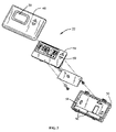
- FIG. 3 is a perspective view of a preferred embodiment of a remote sensor having a transmitting device constructed according to the principles of the present invention therein;
- FIG. 4 is a flow chart showing a preferred embodiment of a process for controlling transmission power according to the present invention.
- the present invention provides for conserving power in a thermostat control system using power saving transmissions.
- a system within which the present invention may be implemented may be implemented.
- this may be further understood with respect to the climate control system shown by example in FIGS. 1 and 2 , and the thermostat unit and remote sensor shown by example in FIGS. 3 and 4 .
- FIG. 1 A preferred embodiment of a climate control system including a thermostat control system having remote internally powered components is shown generally in FIG. 1 .
- the thermostat control system having remote components typically includes a thermostat unit 20 that may be in communication with a plurality of sensors, such as remote sensors 22 .
- the remote sensors 22 may be provided in different rooms of a building 24 (e.g., a residential house) for sensing climate conditions in those rooms and transmitting information relating to the climate conditions to the thermostat unit 20 .
- the climate information may include, for example, the sensed temperature or temperature change, the measured humidity and identification information (e.g., device type ID, unique sensor ID and/or channel number) uniquely identifying the particular remote sensor 22 .
- the measured humidity and identification information e.g., device type ID, unique sensor ID and/or channel number
- Bi-directional communication may also be provided, such that the remote sensors 22 may be configured for receiving control information from the thermostat unit 20 .
- One particular remote climate control system for use with the present invention includes the 1F95-479 thermostat and F0148-1328 remote sensor, both manufactured and sold by the White-Rodgers Division of Emerson Electric Co.
- thermostat unit 20 may be provided within the building 24 and/or a plurality of remote sensors 22 may be provided on different floors or levels of the building 24 .
- Each remote sensor 22 is preferably configured for use with a specific thermostat unit 20 , with the thermostat unit 20 recognizing transmissions from each remote sensor 22 associated therewith as described herein. Also, information may be transmitted from the remote sensors 22 to the thermostat unit 20 or from the thermostat unit 20 to the remote sensors 22 , depending upon climate control system requirements.
- a thermostat unit 20 communicates wirelessly with a plurality of remote sensors 22 to determine climate conditions, as shown in FIG. 1 .
- the thermostat unit 20 processes the climate condition information and controls (e.g., starts heating or cooling cycle) an HVAC system 28 based upon predetermined system settings (e.g., user programmed set-point temperatures stored in a digital programmable thermostat unit 20 ).
- predetermined system settings e.g., user programmed set-point temperatures stored in a digital programmable thermostat unit 20 .
- the thermostat unit 20 may be provided with a local sensor (not shown) for sensing climate conditions near the thermostat unit 20 .
- the thermostat unit 20 may also process information from the local sensor, in addition to the sensors 22 to control the HVAC system 28 .
- a thermostat unit 20 in which the present invention may be implemented includes a base 32 and a removable face or cover 34 adapted for connection to the base 32 .
- the removable face or cover 34 may include an opening 36 for viewing a liquid crystal display used for programming the thermostat unit 20 and obtaining climate control information (e.g., current temperature, set-point temperature, etc.).
- climate control information e.g., current temperature, set-point temperature, etc.
- Buttons 38 provide for programming the thermostat unit 20 (e.g., selecting the set-point temperature).
- the thermostat unit 20 may be provided with an internal compartment (not shown) or similar member having a replaceable power supply (i.e., depletable), which preferably comprises a plurality of batteries (e.g., two AA batteries) for powering components within the thermostat unit 20 .
- the internal replaceable power supply may be utilized when power is temporarily unavailable from an external power source (e.g., main power to thermostat unit 20 fails) to preserve the system or programmed settings of the thermostat unit 20 .
- An example of such a thermostat unit 20 in which the present invention may be implemented is the 1F95 Series thermostat manufactured and sold by the White-Rodgers Division of Emerson Electric Co.
- the internal replaceable power supply may also be used when external power to the thermostat unit 20 is permanently unavailable, such as in a retrofit installation with power to internal components provided by the internal replaceable power supply (e.g., when replacing a single stage system with a multi-stage system having a multi-stage thermostat requiring more than one power source).
- An example of such a thermostat unit 20 in which the present invention may be implemented is the 1F95 Series thermostat manufactured and sold by the White-Rodgers Division of Emerson Electric Co.
- thermostat unit 20 With respect to powering the thermostat unit 20 , power may be needed for a microprocessor 44 or a receiver 46 provided in accordance with the present invention. It should be noted that power for the microprocessor 44 and receiver 46 may be provided from an external source connected directly to the thermostat unit 20 . Further, the thermostat unit 20 preferably includes a controller as part of the microprocessor 44 for controlling operation of the thermostat unit 20 (e.g., activating cooling and/or heating).
- a remote sensor 22 in which the present invention may be implemented includes a removable face or cover 48 adapted for connection to a base 50 .
- An opening 58 may be provided in the face or cover 48 for viewing a liquid crystal display.
- the liquid crystal display may provide system and/or climate control information (e.g., current sensed temperature).
- Buttons 59 are preferably provided for use in obtaining information from and programming the remote sensor 22 .
- the remote sensor 22 is powered by an internal replaceable power supply 56 (i.e., depletable), shown as replaceable batteries (e.g., two AAA batteries), which are provided within an internal compartment 54 .
- Components within the remote sensor 22 preferably include a temperature sensor 60 (eg. temperature sensor circuit), which may be provided in any known manner, and a transmitter 62 adapted for communication with the receiver 46 in accordance with the present invention, and as described herein.
- the remote sensor 22 alternately may be powered by an external power supply.
- An example of such a remote sensor 22 in which the present invention may be implemented is the F0145-1328 remote temperature sensor.
- a transmitter 62 may be provided therewith. Further, in addition to the transmitter 62 in the remote sensor 22 , a receiver 46 may be provided therewith.
- the transmitter 62 and receiver 46 may be provided as a single unit (e.g., a transceiver).
- the transceiver unit 70 of the thermostat 20 comprises an antenna 64 , a transceiver chip 66 , and a processor 68 .
- the transceiver chip 66 receives signals from the antenna, and compares the signal to a reference signal. For example, in the preferred embodiment, the signal is compared to a local oscillator having a frequency of 418 Mhz, and is demodulated into a digital data stream.
- This data is output through a communication link to the processor 68 , which loads the data into a software buffer for protocol verification.
- the processor 68 strips the data and analyzes the synchronization bit at the beginning of the signal to synchronize the transmitted signal and the transceiver chip 66 , and also analyzes the unique serial number within the transmission to verify the signal protocol with stored sensor serial numbers.
- protocol verification of the transmitted signal is completed and the signal verified to be valid, the received data stream is transferred from the processor 68 to the thermostat's microprocessor 44 using synchronized serial communication.
- the transmitted information is not identified or stored by the processor 68 , but rather by the thermostat's microprocessor 44 .
- the microprocessor 44 of the thermostat receives the transmitted data and identifies the sensor letter designation A, B, C etc., to uniquely identify and store the data pertaining to the appropriate sensor unit.
- the transmitter in the temperature sensor 22 is adapted to transmit climate and control information to the transceiver 66 at a plurality of power levels, and preferably at one of two power levels as follows: (1) a lower power level or (2) a higher power level.
- the temperature sensor transmitter transmits at a lower power level more frequently than at a higher power level.
- the transmitted signal is preferably configured as a carrier present/carrier absent continuous Surface Acoustic Wave (SAW) type of transmission.
- SAW Surface Acoustic Wave
- the temperature sensor transmitter is preferably also adapted for transmitting the climate and control information to the transceiver 70 at a plurality of data transfer rates, and more preferably at one of two transfer rates as follows: (1) a lower transfer rate of preferably about 2000 bits per second (bps); or (2) a higher transfer rate of preferably about 4000 bps. More preferably, the lower power transmission is provided at the higher data transfer rate and the higher power transmission is provided at the lower data transfer rate. However, in some embodiments this can also be reversed so that at the lower power the transmission is at the lower data transfer rate, and at higher power the transmission is at the higher data transfer rate.
- the base frequency of the transmitter may be configured as required, and for residential uses, may be provided at about 418 MHz.
- the transmitter in the temperature sensor for transmitting climate or control information at one of two power levels and one of two data transfer rates may be provided by a programmable transmitter chip, such as, for example, a Chipcon Chip #CC1070 manufactured and sold by Chipcon.
- the transceiver chip 66 for receiving climate or control information at one of two power levels and one of two data transfer rates from the transmitter may be provided, for example, by a Chipcon #CC1020 sold and manufactured by Chipcon. It should be noted that if the transmitter is adapted for transmitting at a frequency at which the transceiver is not adapted to receive, the received signal is preferably frequency shifted in a known manner. Further, depending upon the transmission requirements of the particular thermostat control system, a different transmitter or receiver may be provided having different power levels and data transfer rates.
- a remote sensor 22 is activated in a setup or learn mode upon installation.
- the transmitter 62 preferably transmits at predetermined time intervals (e.g., every eleven seconds) a lower power/higher data transfer rate test signal for reception by a receiver 46 or transceiver 70 in a thermostat unit 20 that is also activated in a setup or learn mode.
- the test signal preferably includes a leader to indicate the transfer rate of the signal, which will be included with transmissions during the normal operating mode, and also includes a “flag” or a serial number identification of the particular sensor unit, for use by the thermostat's transceiver unit 46 ′ in identifying future transmissions from the specific remote sensor 22 during the normal operating mode.
- the sensor 22 also prompts the user to assign each sensor with a designation letter A, B, C etc. that is included in the transmission signal, so that the user can relate the temperature displayed on the thermostat for sensor “A” with the room that sensor “A” is in, and likewise for sensors B, C, etc.
- the thermostat unit 20 may be provided with a visual indicator to show the strength of the signal received from the remote sensor 22 in the setup or learn mode in order to determine whether the remote sensor 22 should be installed in a different location to provide better signal transmission strength.
- a visual indicator to show the strength of the signal received from the remote sensor 22 in the setup or learn mode in order to determine whether the remote sensor 22 should be installed in a different location to provide better signal transmission strength.
- An example of such a thermostat unit 20 in which the present invention may be implemented is the 1F95-479 Series thermostat manufactured and sold by the White-Rodgers Division of Emerson Electric Co.
- the transmitter 62 is adapted to transmit once at a higher power/lower data transfer rate after a predetermined number of transmissions.
- the frequency of higher power/lower data rate transmissions may alternatively be based on a time period, and is preferably any suitable means for providing a frequency of reliable higher power transmissions.
- one or more light emitting diodes (LEDs) 70 may be provided in connection with the thermostat unit 20 to preferably indicate signal strength as follows: (1) green indicates strong signal strength; (2) yellow indicates adequate signal strength and the user should consider moving the remote sensor 22 or setting the transmitter 62 to a higher power level only mode; or (3) red indicates unacceptable signal strength requiring moving the remote sensor 22 or setting the transmitter 62 to a higher power level only mode. It should be noted that the setup or learn mode is activated for each remote sensor 22 that will transmit data to the thermostat unit 20 during the normal operating mode.
- the remote sensor 22 and thermostat unit 20 are returned to a normal operating mode. If in the normal operating mode a user determines that the thermostat unit 20 is not properly controlling climate conditions, such as, for example, if a room having a remote sensor 22 therein becomes too warm, this may indicate that signal strength has become weak.
- the weak signal strength may result from, for example, an electronic device that may have been moved in close proximity to the remote sensor 22 and is causing interference.
- the remote sensor 22 and thermostat unit 20 may again be placed in the setup or learn mode in order to identify a better location for the remote sensor 22 or to select a higher power level only transmission mode for operation.
- the transmitter In the normal operating mode (i.e., remote sensor 22 set to transmit at lower power/higher transfer rate more frequently), the transmitter preferably periodically transmits climate and control information to the receiver or transceiver of the thermostat 20 . In this mode, the temperature sensor transmitter preferably transmits only on a sensed temperature change of a predetermined amount.
- the remote sensors 22 sense climate conditions at step 100 at predetermined time intervals. For example, sensing may occur every 30 seconds. Upon sensing a change in climate conditions (e.g., temperature change) that exceeds a predetermined amount (e.g., 3/16° F. temperature change in the normal transmission mode or 6/16° F.
- a predetermined amount e.g., 3/16° F. temperature change in the normal transmission mode or 6/16° F.
- the transmitter transmits a lower power/higher data transfer rate signal to the thermostat transceiver or receiver at 108 , unless a predetermined number of transmissions (e.g., 10 transmissions) since the last higher power/lower data transfer rate transmission has been exceeded at step 106 . If the predetermined number of transmissions has occurred, a higher power/lower data transfer rate signal is transmitted at 110 . If the sensed temperature does not exceed the predetermined temperature change amount, the sensors 22 continue to sense climate conditions at 100 to obtain climate information for use in the next transmission.
- a predetermined number of transmissions e.g. 10 transmissions
- the sensors 22 may be configured to sense temperature conditions at, for example, random time intervals, fixed time intervals, or a time intervals dependent upon a variable number or value (e.g., last sensed temperature value) at 100 .
- thermostat unit 20 As part of a climate control system 26 , including a thermostat unit 20 and remote sensors 22 , it should be appreciated that different or additional components may be provided as part of the climate control system 26 . This may include different thermostat units and sensing devices. Further, a different transmitter may be provided for transmitting a Surface Acoustic Wave carrier present/carrier absent signal, a different type of signal or a different type of carrier wave. Further, more than two power levels and two data transfer rates may be provided in connection with the present invention. Also, transmissions between the various devices of the thermostat control system may be modified, including the time periods and conditions for transmitting information.
Abstract
Description
Claims (20)
Priority Applications (2)
| Application Number | Priority Date | Filing Date | Title |
|---|---|---|---|
| US10/990,897 US7537171B2 (en) | 2004-11-17 | 2004-11-17 | Thermostat control system providing power saving transmissions |
| US12/471,957 US20090236433A1 (en) | 2004-11-17 | 2009-05-26 | Thermostat control system providing power saving transmissions |
Applications Claiming Priority (1)
| Application Number | Priority Date | Filing Date | Title |
|---|---|---|---|
| US10/990,897 US7537171B2 (en) | 2004-11-17 | 2004-11-17 | Thermostat control system providing power saving transmissions |
Related Child Applications (1)
| Application Number | Title | Priority Date | Filing Date |
|---|---|---|---|
| US12/471,957 Division US20090236433A1 (en) | 2004-11-17 | 2009-05-26 | Thermostat control system providing power saving transmissions |
Publications (2)
| Publication Number | Publication Date |
|---|---|
| US20060102731A1 US20060102731A1 (en) | 2006-05-18 |
| US7537171B2 true US7537171B2 (en) | 2009-05-26 |
Family
ID=36385218
Family Applications (2)
| Application Number | Title | Priority Date | Filing Date |
|---|---|---|---|
| US10/990,897 Active 2026-08-16 US7537171B2 (en) | 2004-11-17 | 2004-11-17 | Thermostat control system providing power saving transmissions |
| US12/471,957 Abandoned US20090236433A1 (en) | 2004-11-17 | 2009-05-26 | Thermostat control system providing power saving transmissions |
Family Applications After (1)
| Application Number | Title | Priority Date | Filing Date |
|---|---|---|---|
| US12/471,957 Abandoned US20090236433A1 (en) | 2004-11-17 | 2009-05-26 | Thermostat control system providing power saving transmissions |
Country Status (1)
| Country | Link |
|---|---|
| US (2) | US7537171B2 (en) |
Cited By (66)
| Publication number | Priority date | Publication date | Assignee | Title |
|---|---|---|---|---|
| WO2013052901A2 (en) * | 2011-10-06 | 2013-04-11 | Nest Labs, Inc. | Strategic reduction of power usage in multi-sensing, wirelessly communicating learning thermostat |
| US8478447B2 (en) | 2010-11-19 | 2013-07-02 | Nest Labs, Inc. | Computational load distribution in a climate control system having plural sensing microsystems |
| US8489243B2 (en) | 2010-11-19 | 2013-07-16 | Nest Labs, Inc. | Thermostat user interface |
| US8511577B2 (en) | 2011-02-24 | 2013-08-20 | Nest Labs, Inc. | Thermostat with power stealing delay interval at transitions between power stealing states |
| US8511576B2 (en) | 2011-02-24 | 2013-08-20 | Nest Labs, Inc. | Power management in energy buffered building control unit |
| US8523083B2 (en) | 2011-02-24 | 2013-09-03 | Nest Labs, Inc. | Thermostat with self-configuring connections to facilitate do-it-yourself installation |
| US8539567B1 (en) | 2012-09-22 | 2013-09-17 | Nest Labs, Inc. | Multi-tiered authentication methods for facilitating communications amongst smart home devices and cloud-based servers |
| WO2013149160A1 (en) * | 2012-03-29 | 2013-10-03 | Nest Labs, Inc. | Enclosure cooling using early compressor turn-off with extended fan operation |
| US8594850B1 (en) | 2012-09-30 | 2013-11-26 | Nest Labs, Inc. | Updating control software on a network-connected HVAC controller |
| US8620841B1 (en) | 2012-08-31 | 2013-12-31 | Nest Labs, Inc. | Dynamic distributed-sensor thermostat network for forecasting external events |
| US8627127B2 (en) | 2011-02-24 | 2014-01-07 | Nest Labs, Inc. | Power-preserving communications architecture with long-polling persistent cloud channel for wireless network-connected thermostat |
| US8630741B1 (en) | 2012-09-30 | 2014-01-14 | Nest Labs, Inc. | Automated presence detection and presence-related control within an intelligent controller |
| US8635373B1 (en) | 2012-09-22 | 2014-01-21 | Nest Labs, Inc. | Subscription-Notification mechanisms for synchronization of distributed states |
| US20140051350A1 (en) * | 2007-12-18 | 2014-02-20 | Gilat Satellite Networks Ltd. | Multi-Dimensional Adaptive Transmission Technique |
| US8659302B1 (en) | 2012-09-21 | 2014-02-25 | Nest Labs, Inc. | Monitoring and recoverable protection of thermostat switching circuitry |
| US20140085092A1 (en) * | 2012-09-21 | 2014-03-27 | Nest Labs, Inc. | Cover plate for a hazard detector having improved air flow and other characteristics |
| US8695888B2 (en) | 2004-10-06 | 2014-04-15 | Nest Labs, Inc. | Electronically-controlled register vent for zone heating and cooling |
| US8708242B2 (en) | 2012-09-21 | 2014-04-29 | Nest Labs, Inc. | Thermostat system with software-repurposable wiring terminals adaptable for HVAC systems of different ranges of complexity |
| US8843239B2 (en) | 2010-11-19 | 2014-09-23 | Nest Labs, Inc. | Methods, systems, and related architectures for managing network connected thermostats |
| US8918219B2 (en) | 2010-11-19 | 2014-12-23 | Google Inc. | User friendly interface for control unit |
| US9007222B2 (en) | 2012-09-21 | 2015-04-14 | Google Inc. | Detector unit and sensing chamber therefor |
| US9046414B2 (en) | 2012-09-21 | 2015-06-02 | Google Inc. | Selectable lens button for a hazard detector and method therefor |
| US9092039B2 (en) | 2010-11-19 | 2015-07-28 | Google Inc. | HVAC controller with user-friendly installation features with wire insertion detection |
| US9098096B2 (en) | 2012-04-05 | 2015-08-04 | Google Inc. | Continuous intelligent-control-system update using information requests directed to user devices |
| US9122283B2 (en) | 2013-04-19 | 2015-09-01 | Emerson Electric Co. | Battery power management in a thermostat with a wireless transceiver |
| US9175871B2 (en) | 2011-10-07 | 2015-11-03 | Google Inc. | Thermostat user interface |
| US9208676B2 (en) | 2013-03-14 | 2015-12-08 | Google Inc. | Devices, methods, and associated information processing for security in a smart-sensored home |
| US9268344B2 (en) | 2010-11-19 | 2016-02-23 | Google Inc. | Installation of thermostat powered by rechargeable battery |
| US9298196B2 (en) | 2010-11-19 | 2016-03-29 | Google Inc. | Energy efficiency promoting schedule learning algorithms for intelligent thermostat |
| US9342082B2 (en) | 2010-12-31 | 2016-05-17 | Google Inc. | Methods for encouraging energy-efficient behaviors based on a network connected thermostat-centric energy efficiency platform |
| US9396633B1 (en) | 2015-06-14 | 2016-07-19 | Google Inc. | Systems, methods, and devices for managing coexistence of multiple transceiver devices by optimizing component layout |
| US9448567B2 (en) | 2010-11-19 | 2016-09-20 | Google Inc. | Power management in single circuit HVAC systems and in multiple circuit HVAC systems |
| US9453655B2 (en) | 2011-10-07 | 2016-09-27 | Google Inc. | Methods and graphical user interfaces for reporting performance information for an HVAC system controlled by a self-programming network-connected thermostat |
| US9459018B2 (en) | 2010-11-19 | 2016-10-04 | Google Inc. | Systems and methods for energy-efficient control of an energy-consuming system |
| US9513642B2 (en) | 2010-11-19 | 2016-12-06 | Google Inc. | Flexible functionality partitioning within intelligent-thermostat-controlled HVAC systems |
| US9543998B2 (en) | 2015-06-14 | 2017-01-10 | Google Inc. | Systems, methods, and devices for managing coexistence of multiple transceiver devices using bypass circuitry |
| US9568201B2 (en) | 2014-03-28 | 2017-02-14 | Google Inc. | Environmental control system retrofittable with multiple types of boiler-based heating systems |
| US9581342B2 (en) | 2014-03-28 | 2017-02-28 | Google Inc. | Mounting stand for multi-sensing environmental control device |
| US9595070B2 (en) | 2013-03-15 | 2017-03-14 | Google Inc. | Systems, apparatus and methods for managing demand-response programs and events |
| US9609462B2 (en) | 2014-03-28 | 2017-03-28 | Google Inc. | Facilitating radio frequency communications among environmental control system components |
| US9612031B2 (en) | 2015-01-07 | 2017-04-04 | Google Inc. | Thermostat switching circuitry robust against anomalous HVAC control line conditions |
| US9639100B2 (en) | 2011-12-06 | 2017-05-02 | Trane International Inc. | Power-sensing circuit for wireless zone sensors |
| US9679454B2 (en) | 2015-02-06 | 2017-06-13 | Google Inc. | Systems, methods, and devices for managing coexistence of multiple transceiver devices using control signals |
| US9794522B2 (en) | 2015-02-06 | 2017-10-17 | Google Inc. | Systems, methods, and devices for managing coexistence of multiple transceiver devices by optimizing component layout |
| US9791839B2 (en) | 2014-03-28 | 2017-10-17 | Google Inc. | User-relocatable self-learning environmental control device capable of adapting previous learnings to current location in controlled environment |
| US9807099B2 (en) | 2013-03-15 | 2017-10-31 | Google Inc. | Utility portals for managing demand-response events |
| US9810442B2 (en) | 2013-03-15 | 2017-11-07 | Google Inc. | Controlling an HVAC system in association with a demand-response event with an intelligent network-connected thermostat |
| US9810590B2 (en) | 2010-09-14 | 2017-11-07 | Google Inc. | System and method for integrating sensors in thermostats |
| US9851728B2 (en) | 2010-12-31 | 2017-12-26 | Google Inc. | Inhibiting deleterious control coupling in an enclosure having multiple HVAC regions |
| US9890970B2 (en) | 2012-03-29 | 2018-02-13 | Google Inc. | Processing and reporting usage information for an HVAC system controlled by a network-connected thermostat |
| US9952573B2 (en) | 2010-11-19 | 2018-04-24 | Google Llc | Systems and methods for a graphical user interface of a controller for an energy-consuming system having spatially related discrete display elements |
| US10078319B2 (en) | 2010-11-19 | 2018-09-18 | Google Llc | HVAC schedule establishment in an intelligent, network-connected thermostat |
| US20180287385A1 (en) * | 2009-07-30 | 2018-10-04 | Lutron Electronics Co., Inc. | Load Control System Providing Manual Override of an Energy Savings Mode |
| US10145577B2 (en) | 2012-03-29 | 2018-12-04 | Google Llc | User interfaces for HVAC schedule display and modification on smartphone or other space-limited touchscreen device |
| US10333810B2 (en) * | 2017-06-09 | 2019-06-25 | Johnson Controls Technology Company | Control system with asynchronous wireless data transmission |
| US10346275B2 (en) | 2010-11-19 | 2019-07-09 | Google Llc | Attributing causation for energy usage and setpoint changes with a network-connected thermostat |
| US10443879B2 (en) | 2010-12-31 | 2019-10-15 | Google Llc | HVAC control system encouraging energy efficient user behaviors in plural interactive contexts |
| US10613213B2 (en) | 2016-05-13 | 2020-04-07 | Google Llc | Systems, methods, and devices for utilizing radar with smart devices |
| US10687184B2 (en) | 2016-05-13 | 2020-06-16 | Google Llc | Systems, methods, and devices for utilizing radar-based touch interfaces |
| US10739028B2 (en) | 2017-06-09 | 2020-08-11 | Johnson Controls Technology Company | Thermostat with efficient wireless data transmission |
| US10771868B2 (en) | 2010-09-14 | 2020-09-08 | Google Llc | Occupancy pattern detection, estimation and prediction |
| US10868857B2 (en) | 2017-04-21 | 2020-12-15 | Johnson Controls Technology Company | Building management system with distributed data collection and gateway services |
| US10992175B2 (en) | 2018-06-15 | 2021-04-27 | Google Llc | Communication circuit for 2-wire protocols between HVAC systems and smart-home devices |
| US20210180815A1 (en) * | 2004-11-18 | 2021-06-17 | Ubiquitous Connectivity, Lp | Ubiquitous Connectivity and Control System for Remote Locations |
| US11334034B2 (en) | 2010-11-19 | 2022-05-17 | Google Llc | Energy efficiency promoting schedule learning algorithms for intelligent thermostat |
| US11570685B2 (en) * | 2018-10-24 | 2023-01-31 | Carrier Corporation | Power savings for wireless sensors |
Families Citing this family (24)
| Publication number | Priority date | Publication date | Assignee | Title |
|---|---|---|---|---|
| US8029608B1 (en) * | 2006-12-13 | 2011-10-04 | BD Technology Partners | Furnace filter indicator |
| GB0710087D0 (en) * | 2007-05-25 | 2007-07-04 | Heat Energy And Associated Tec | Multi-zone heating system |
| US7764171B2 (en) * | 2007-09-24 | 2010-07-27 | Computime, Ltd. | Adjusting a communications channel between control unit and remote sensor |
| CN102575191A (en) * | 2009-10-07 | 2012-07-11 | 宝洁公司 | Detergent composition |
| US8421647B2 (en) * | 2009-12-10 | 2013-04-16 | General Electric Company | Use of one LED to represent various utility rates and system status by varying frequency and/or duty cycle of LED |
| DE102010001199A1 (en) * | 2010-01-26 | 2011-07-28 | Robert Bosch GmbH, 70469 | Control device for a heating device and system for controlling a heating system |
| US9329903B2 (en) * | 2010-05-12 | 2016-05-03 | Emerson Electric Co. | System and method for internet based service notification |
| US9098279B2 (en) | 2010-09-14 | 2015-08-04 | Google Inc. | Methods and systems for data interchange between a network-connected thermostat and cloud-based management server |
| CN102011640A (en) * | 2010-10-19 | 2011-04-13 | 韩培洲 | Primary-cylinder four-stroke intercooled regenerative internal-combustion engine |
| EP2521426B1 (en) * | 2011-04-28 | 2015-09-16 | Helvar Oy Ab | Device and method for controlling lighting control system |
| US9940884B1 (en) * | 2012-08-31 | 2018-04-10 | Sergey Musolin | Automated dimmer wall switch with a color multi-touch LCD/LED display |
| CN106471869B (en) * | 2014-06-30 | 2019-12-10 | 飞利浦照明控股有限公司 | Device management |
| AU2015349615A1 (en) * | 2014-11-18 | 2017-06-29 | Station Innovation Pty Ltd | Remote monitoring system |
| CN104808718B (en) * | 2015-03-10 | 2017-06-06 | 广东美的暖通设备有限公司 | The temprature control method of heat pump water-heating machine, temperature control equipment |
| JP6409629B2 (en) | 2015-03-11 | 2018-10-24 | オムロン株式会社 | Sensor system |
| US9552715B2 (en) | 2015-04-27 | 2017-01-24 | BD Technology Partners | Networked filter condition indicator |
| US20170051931A1 (en) * | 2015-08-17 | 2017-02-23 | Joseph A Logan | Method for Scheduling Heating/ Cooling for a Climate Controlled Area |
| CN105867463A (en) * | 2016-05-24 | 2016-08-17 | 桂林市思奇通信设备有限公司 | Wireless temperature control system of broadcast transmitter |
| US10989419B2 (en) * | 2017-10-02 | 2021-04-27 | Ademco Inc. | Hydronic floor heating systems with features |
| US10739030B2 (en) | 2018-03-06 | 2020-08-11 | Google Llc | Self-learning temperature monitor and control system and methods for making and using same |
| US10895509B2 (en) | 2018-03-06 | 2021-01-19 | Google Llc | Dynamic scanning of remote temperature sensors |
| EP3557365B1 (en) * | 2018-04-16 | 2021-06-02 | Google LLC | Dynamic scanning of remote temperature sensors |
| US11236923B2 (en) * | 2018-10-10 | 2022-02-01 | Ademco Inc. | Thermostat with sensor priority screen |
| CN113849019B (en) * | 2021-09-14 | 2022-04-08 | 至誉科技(武汉)有限公司 | Intelligent management system and method based on CFexpress card reader |
Citations (10)
| Publication number | Priority date | Publication date | Assignee | Title |
|---|---|---|---|---|
| US3883368A (en) * | 1972-10-26 | 1975-05-13 | Union Carbide Corp | Alkaline aluminum-air/zinc-manganese dioxide hybrid battery |
| US5390206A (en) | 1991-10-01 | 1995-02-14 | American Standard Inc. | Wireless communication system for air distribution system |
| US5596313A (en) * | 1995-05-16 | 1997-01-21 | Personal Security & Safety Systems, Inc. | Dual power security location system |
| US5595342A (en) | 1993-05-24 | 1997-01-21 | British Gas Plc | Control system |
| US5711480A (en) | 1996-10-15 | 1998-01-27 | Carrier Corporation | Low-cost wireless HVAC systems |
| US5927599A (en) | 1997-03-12 | 1999-07-27 | Marley Electric Heating | Wireless air conditioning control system |
| US6213404B1 (en) * | 1993-07-08 | 2001-04-10 | Dushane Steve | Remote temperature sensing transmitting and programmable thermostat system |
| US6453689B2 (en) * | 2000-03-02 | 2002-09-24 | Sanyo Electric Co., Ltd | Refrigerating/air-conditioning apparatus and control method therefor |
| US6513723B1 (en) * | 2000-09-28 | 2003-02-04 | Emerson Electric Co. | Method and apparatus for automatically transmitting temperature information to a thermostat |
| US20030228890A1 (en) * | 2002-06-06 | 2003-12-11 | Nec Corporation | Measurement technique for a radio access telecommunications terminal |
Family Cites Families (6)
| Publication number | Priority date | Publication date | Assignee | Title |
|---|---|---|---|---|
| US3833368A (en) * | 1972-12-04 | 1974-09-03 | Polaroid Corp | Photographic products incorporating anti-reflection coatings |
| US5602758A (en) * | 1993-01-22 | 1997-02-11 | Gas Research Institute | Installation link-up procedure |
| US7298748B2 (en) * | 2001-09-28 | 2007-11-20 | Kabushiki Kaisha Toshiba | Method of packet transmission and wireless communication device |
| US6983889B2 (en) * | 2003-03-21 | 2006-01-10 | Home Comfort Zones, Inc. | Forced-air zone climate control system for existing residential houses |
| US6902117B1 (en) * | 2003-04-21 | 2005-06-07 | Howard Rosen | Wireless transmission of temperature determining signals to a programmable thermostat |
| US7151264B2 (en) * | 2004-12-21 | 2006-12-19 | Ranco Incorporated Of Delaware | Inline air handler system and associated method of use |
-
2004
- 2004-11-17 US US10/990,897 patent/US7537171B2/en active Active
-
2009
- 2009-05-26 US US12/471,957 patent/US20090236433A1/en not_active Abandoned
Patent Citations (10)
| Publication number | Priority date | Publication date | Assignee | Title |
|---|---|---|---|---|
| US3883368A (en) * | 1972-10-26 | 1975-05-13 | Union Carbide Corp | Alkaline aluminum-air/zinc-manganese dioxide hybrid battery |
| US5390206A (en) | 1991-10-01 | 1995-02-14 | American Standard Inc. | Wireless communication system for air distribution system |
| US5595342A (en) | 1993-05-24 | 1997-01-21 | British Gas Plc | Control system |
| US6213404B1 (en) * | 1993-07-08 | 2001-04-10 | Dushane Steve | Remote temperature sensing transmitting and programmable thermostat system |
| US5596313A (en) * | 1995-05-16 | 1997-01-21 | Personal Security & Safety Systems, Inc. | Dual power security location system |
| US5711480A (en) | 1996-10-15 | 1998-01-27 | Carrier Corporation | Low-cost wireless HVAC systems |
| US5927599A (en) | 1997-03-12 | 1999-07-27 | Marley Electric Heating | Wireless air conditioning control system |
| US6453689B2 (en) * | 2000-03-02 | 2002-09-24 | Sanyo Electric Co., Ltd | Refrigerating/air-conditioning apparatus and control method therefor |
| US6513723B1 (en) * | 2000-09-28 | 2003-02-04 | Emerson Electric Co. | Method and apparatus for automatically transmitting temperature information to a thermostat |
| US20030228890A1 (en) * | 2002-06-06 | 2003-12-11 | Nec Corporation | Measurement technique for a radio access telecommunications terminal |
Cited By (198)
| Publication number | Priority date | Publication date | Assignee | Title |
|---|---|---|---|---|
| US9273879B2 (en) | 2004-10-06 | 2016-03-01 | Google Inc. | Occupancy-based wireless control of multiple environmental zones via a central controller |
| US10215437B2 (en) | 2004-10-06 | 2019-02-26 | Google Llc | Battery-operated wireless zone controllers having multiple states of power-related operation |
| US9182140B2 (en) | 2004-10-06 | 2015-11-10 | Google Inc. | Battery-operated wireless zone controllers having multiple states of power-related operation |
| US9194600B2 (en) | 2004-10-06 | 2015-11-24 | Google Inc. | Battery charging by mechanical impeller at forced air vent outputs |
| US9194599B2 (en) | 2004-10-06 | 2015-11-24 | Google Inc. | Control of multiple environmental zones based on predicted changes to environmental conditions of the zones |
| US9222692B2 (en) | 2004-10-06 | 2015-12-29 | Google Inc. | Wireless zone control via mechanically adjustable airflow elements |
| US9618223B2 (en) | 2004-10-06 | 2017-04-11 | Google Inc. | Multi-nodal thermostat control system |
| US9303889B2 (en) | 2004-10-06 | 2016-04-05 | Google Inc. | Multiple environmental zone control via a central controller |
| US9316407B2 (en) | 2004-10-06 | 2016-04-19 | Google Inc. | Multiple environmental zone control with integrated battery status communications |
| US9995497B2 (en) | 2004-10-06 | 2018-06-12 | Google Llc | Wireless zone control via mechanically adjustable airflow elements |
| US9353964B2 (en) | 2004-10-06 | 2016-05-31 | Google Inc. | Systems and methods for wirelessly-enabled HVAC control |
| US9353963B2 (en) | 2004-10-06 | 2016-05-31 | Google Inc. | Occupancy-based wireless control of multiple environmental zones with zone controller identification |
| US8695888B2 (en) | 2004-10-06 | 2014-04-15 | Nest Labs, Inc. | Electronically-controlled register vent for zone heating and cooling |
| US10126011B2 (en) | 2004-10-06 | 2018-11-13 | Google Llc | Multiple environmental zone control with integrated battery status communications |
| US20210180815A1 (en) * | 2004-11-18 | 2021-06-17 | Ubiquitous Connectivity, Lp | Ubiquitous Connectivity and Control System for Remote Locations |
| US20140051350A1 (en) * | 2007-12-18 | 2014-02-20 | Gilat Satellite Networks Ltd. | Multi-Dimensional Adaptive Transmission Technique |
| US8818446B2 (en) * | 2007-12-18 | 2014-08-26 | Gilat Satellite Networks Ltd. | Multi-dimensional adaptive transmission technique |
| US11293223B2 (en) | 2009-07-30 | 2022-04-05 | Lutron Technology Company Llc | Load control system providing manual override of an energy savings mode |
| US10756541B2 (en) * | 2009-07-30 | 2020-08-25 | Lutron Technology Company Llc | Load control system providing manual override of an energy savings mode |
| US20180287385A1 (en) * | 2009-07-30 | 2018-10-04 | Lutron Electronics Co., Inc. | Load Control System Providing Manual Override of an Energy Savings Mode |
| US9605858B2 (en) | 2010-09-14 | 2017-03-28 | Google Inc. | Thermostat circuitry for connection to HVAC systems |
| US9810590B2 (en) | 2010-09-14 | 2017-11-07 | Google Inc. | System and method for integrating sensors in thermostats |
| US9494332B2 (en) | 2010-09-14 | 2016-11-15 | Google Inc. | Thermostat wiring connector |
| US10771868B2 (en) | 2010-09-14 | 2020-09-08 | Google Llc | Occupancy pattern detection, estimation and prediction |
| US9279595B2 (en) | 2010-09-14 | 2016-03-08 | Google Inc. | Methods, systems, and related architectures for managing network connected thermostats |
| US9702579B2 (en) | 2010-09-14 | 2017-07-11 | Google Inc. | Strategic reduction of power usage in multi-sensing, wirelessly communicating learning thermostat |
| US9715239B2 (en) | 2010-09-14 | 2017-07-25 | Google Inc. | Computational load distribution in an environment having multiple sensing microsystems |
| US9804610B2 (en) | 2010-09-14 | 2017-10-31 | Google Inc. | Thermostat user interface |
| US9026254B2 (en) | 2010-09-14 | 2015-05-05 | Google Inc. | Strategic reduction of power usage in multi-sensing, wirelessly communicating learning thermostat |
| US9261287B2 (en) | 2010-09-14 | 2016-02-16 | Google Inc. | Adaptive power stealing thermostat |
| US9684317B2 (en) | 2010-09-14 | 2017-06-20 | Google Inc. | Thermostat facilitating user-friendly installation thereof |
| US9223323B2 (en) | 2010-09-14 | 2015-12-29 | Google Inc. | User friendly interface for control unit |
| US10309672B2 (en) | 2010-09-14 | 2019-06-04 | Google Llc | Thermostat wiring connector |
| US9696734B2 (en) | 2010-09-14 | 2017-07-04 | Google Inc. | Active power stealing |
| US10082307B2 (en) | 2010-09-14 | 2018-09-25 | Google Llc | Adaptive power-stealing thermostat |
| US9612032B2 (en) | 2010-09-14 | 2017-04-04 | Google Inc. | User friendly interface for control unit |
| US9459018B2 (en) | 2010-11-19 | 2016-10-04 | Google Inc. | Systems and methods for energy-efficient control of an energy-consuming system |
| US9995499B2 (en) | 2010-11-19 | 2018-06-12 | Google Llc | Electronic device controller with user-friendly installation features |
| US10627791B2 (en) | 2010-11-19 | 2020-04-21 | Google Llc | Thermostat user interface |
| US9026232B2 (en) | 2010-11-19 | 2015-05-05 | Google Inc. | Thermostat user interface |
| US10175668B2 (en) | 2010-11-19 | 2019-01-08 | Google Llc | Systems and methods for energy-efficient control of an energy-consuming system |
| US9766606B2 (en) | 2010-11-19 | 2017-09-19 | Google Inc. | Thermostat user interface |
| US10606724B2 (en) | 2010-11-19 | 2020-03-31 | Google Llc | Attributing causation for energy usage and setpoint changes with a network-connected thermostat |
| US9851729B2 (en) | 2010-11-19 | 2017-12-26 | Google Inc. | Power-preserving communications architecture with long-polling persistent cloud channel for wireless network-connected thermostat |
| US10481780B2 (en) | 2010-11-19 | 2019-11-19 | Google Llc | Adjusting proximity thresholds for activating a device user interface |
| US9092040B2 (en) | 2010-11-19 | 2015-07-28 | Google Inc. | HVAC filter monitoring |
| US9092039B2 (en) | 2010-11-19 | 2015-07-28 | Google Inc. | HVAC controller with user-friendly installation features with wire insertion detection |
| US10452083B2 (en) | 2010-11-19 | 2019-10-22 | Google Llc | Power management in single circuit HVAC systems and in multiple circuit HVAC systems |
| US8478447B2 (en) | 2010-11-19 | 2013-07-02 | Nest Labs, Inc. | Computational load distribution in a climate control system having plural sensing microsystems |
| US10732651B2 (en) | 2010-11-19 | 2020-08-04 | Google Llc | Smart-home proxy devices with long-polling |
| US9127853B2 (en) | 2010-11-19 | 2015-09-08 | Google Inc. | Thermostat with ring-shaped control member |
| US8489243B2 (en) | 2010-11-19 | 2013-07-16 | Nest Labs, Inc. | Thermostat user interface |
| US9952573B2 (en) | 2010-11-19 | 2018-04-24 | Google Llc | Systems and methods for a graphical user interface of a controller for an energy-consuming system having spatially related discrete display elements |
| US11372433B2 (en) | 2010-11-19 | 2022-06-28 | Google Llc | Thermostat user interface |
| US10346275B2 (en) | 2010-11-19 | 2019-07-09 | Google Llc | Attributing causation for energy usage and setpoint changes with a network-connected thermostat |
| US9448567B2 (en) | 2010-11-19 | 2016-09-20 | Google Inc. | Power management in single circuit HVAC systems and in multiple circuit HVAC systems |
| US9575496B2 (en) | 2010-11-19 | 2017-02-21 | Google Inc. | HVAC controller with user-friendly installation features with wire insertion detection |
| US8924027B2 (en) | 2010-11-19 | 2014-12-30 | Google Inc. | Computational load distribution in a climate control system having plural sensing microsystems |
| US8918219B2 (en) | 2010-11-19 | 2014-12-23 | Google Inc. | User friendly interface for control unit |
| US8868219B2 (en) | 2010-11-19 | 2014-10-21 | Google Inc. | Thermostat user interface |
| US10241482B2 (en) | 2010-11-19 | 2019-03-26 | Google Llc | Thermostat user interface |
| US10078319B2 (en) | 2010-11-19 | 2018-09-18 | Google Llc | HVAC schedule establishment in an intelligent, network-connected thermostat |
| US8843239B2 (en) | 2010-11-19 | 2014-09-23 | Nest Labs, Inc. | Methods, systems, and related architectures for managing network connected thermostats |
| US9268344B2 (en) | 2010-11-19 | 2016-02-23 | Google Inc. | Installation of thermostat powered by rechargeable battery |
| US11334034B2 (en) | 2010-11-19 | 2022-05-17 | Google Llc | Energy efficiency promoting schedule learning algorithms for intelligent thermostat |
| US9513642B2 (en) | 2010-11-19 | 2016-12-06 | Google Inc. | Flexible functionality partitioning within intelligent-thermostat-controlled HVAC systems |
| US10747242B2 (en) | 2010-11-19 | 2020-08-18 | Google Llc | Thermostat user interface |
| US8706270B2 (en) | 2010-11-19 | 2014-04-22 | Nest Labs, Inc. | Thermostat user interface |
| US9298196B2 (en) | 2010-11-19 | 2016-03-29 | Google Inc. | Energy efficiency promoting schedule learning algorithms for intelligent thermostat |
| US8757507B2 (en) | 2010-11-19 | 2014-06-24 | Nest Labs, Inc. | Thermostat facilitating user-friendly installation thereof |
| US8752771B2 (en) | 2010-11-19 | 2014-06-17 | Nest Labs, Inc. | Thermostat battery recharging during HVAC function active and inactive states |
| US10151501B2 (en) | 2010-11-19 | 2018-12-11 | Google Llc | Thermostat facilitating user-friendly installation thereof |
| US10191727B2 (en) | 2010-11-19 | 2019-01-29 | Google Llc | Installation of thermostat powered by rechargeable battery |
| US9342082B2 (en) | 2010-12-31 | 2016-05-17 | Google Inc. | Methods for encouraging energy-efficient behaviors based on a network connected thermostat-centric energy efficiency platform |
| US10443879B2 (en) | 2010-12-31 | 2019-10-15 | Google Llc | HVAC control system encouraging energy efficient user behaviors in plural interactive contexts |
| US9851728B2 (en) | 2010-12-31 | 2017-12-26 | Google Inc. | Inhibiting deleterious control coupling in an enclosure having multiple HVAC regions |
| US8944338B2 (en) | 2011-02-24 | 2015-02-03 | Google Inc. | Thermostat with self-configuring connections to facilitate do-it-yourself installation |
| US9933794B2 (en) | 2011-02-24 | 2018-04-03 | Google Llc | Thermostat with self-configuring connections to facilitate do-it-yourself installation |
| US9046898B2 (en) | 2011-02-24 | 2015-06-02 | Google Inc. | Power-preserving communications architecture with long-polling persistent cloud channel for wireless network-connected thermostat |
| US9086703B2 (en) | 2011-02-24 | 2015-07-21 | Google Inc. | Thermostat with power stealing delay interval at transitions between power stealing states |
| US9116529B2 (en) | 2011-02-24 | 2015-08-25 | Google Inc. | Thermostat with self-configuring connections to facilitate do-it-yourself installation |
| US8511577B2 (en) | 2011-02-24 | 2013-08-20 | Nest Labs, Inc. | Thermostat with power stealing delay interval at transitions between power stealing states |
| US8770491B2 (en) | 2011-02-24 | 2014-07-08 | Nest Labs Inc. | Thermostat with power stealing delay interval at transitions between power stealing states |
| US8511576B2 (en) | 2011-02-24 | 2013-08-20 | Nest Labs, Inc. | Power management in energy buffered building control unit |
| US8627127B2 (en) | 2011-02-24 | 2014-01-07 | Nest Labs, Inc. | Power-preserving communications architecture with long-polling persistent cloud channel for wireless network-connected thermostat |
| US8788103B2 (en) | 2011-02-24 | 2014-07-22 | Nest Labs, Inc. | Power management in energy buffered building control unit |
| US8523083B2 (en) | 2011-02-24 | 2013-09-03 | Nest Labs, Inc. | Thermostat with self-configuring connections to facilitate do-it-yourself installation |
| US9435559B2 (en) | 2011-02-24 | 2016-09-06 | Google Inc. | Power management in energy buffered building control unit |
| US9952608B2 (en) | 2011-02-24 | 2018-04-24 | Google Llc | Thermostat with power stealing delay interval at transitions between power stealing states |
| US10684633B2 (en) | 2011-02-24 | 2020-06-16 | Google Llc | Smart thermostat with active power stealing an processor isolation from switching elements |
| WO2013052901A3 (en) * | 2011-10-06 | 2014-05-22 | Nest Labs, Inc. | Strategic reduction of power usage in multi-sensing, wirelessly communicating learning thermostat |
| WO2013052901A2 (en) * | 2011-10-06 | 2013-04-11 | Nest Labs, Inc. | Strategic reduction of power usage in multi-sensing, wirelessly communicating learning thermostat |
| US9453655B2 (en) | 2011-10-07 | 2016-09-27 | Google Inc. | Methods and graphical user interfaces for reporting performance information for an HVAC system controlled by a self-programming network-connected thermostat |
| US9175871B2 (en) | 2011-10-07 | 2015-11-03 | Google Inc. | Thermostat user interface |
| US9920946B2 (en) | 2011-10-07 | 2018-03-20 | Google Llc | Remote control of a smart home device |
| US10873632B2 (en) | 2011-10-17 | 2020-12-22 | Google Llc | Methods, systems, and related architectures for managing network connected devices |
| US9910577B2 (en) | 2011-10-21 | 2018-03-06 | Google Llc | Prospective determination of processor wake-up conditions in energy buffered HVAC control unit having a preconditioning feature |
| US9234668B2 (en) * | 2011-10-21 | 2016-01-12 | Google Inc. | User-friendly, network connected learning thermostat and related systems and methods |
| US9175868B2 (en) | 2011-10-21 | 2015-11-03 | Google Inc. | Thermostat user interface |
| CN103890667A (en) * | 2011-10-21 | 2014-06-25 | 耐斯特实验公司 | User-friendly, network connected learning thermostat and related systems and methods |
| US8942853B2 (en) | 2011-10-21 | 2015-01-27 | Google Inc. | Prospective determination of processor wake-up conditions in energy buffered HVAC control unit |
| US20130173064A1 (en) * | 2011-10-21 | 2013-07-04 | Nest Labs, Inc. | User-friendly, network connected learning thermostat and related systems and methods |
| US9291359B2 (en) | 2011-10-21 | 2016-03-22 | Google Inc. | Thermostat user interface |
| US9720585B2 (en) | 2011-10-21 | 2017-08-01 | Google Inc. | User friendly interface |
| US9740385B2 (en) | 2011-10-21 | 2017-08-22 | Google Inc. | User-friendly, network-connected, smart-home controller and related systems and methods |
| US10678416B2 (en) | 2011-10-21 | 2020-06-09 | Google Llc | Occupancy-based operating state determinations for sensing or control systems |
| US8532827B2 (en) | 2011-10-21 | 2013-09-10 | Nest Labs, Inc. | Prospective determination of processor wake-up conditions in energy buffered HVAC control unit |
| US8998102B2 (en) | 2011-10-21 | 2015-04-07 | Google Inc. | Round thermostat with flanged rotatable user input member and wall-facing optical sensor that senses rotation |
| WO2013058820A1 (en) * | 2011-10-21 | 2013-04-25 | Nest Labs, Inc. | User-friendly, network connected learning thermostat and related systems and methods |
| US9639100B2 (en) | 2011-12-06 | 2017-05-02 | Trane International Inc. | Power-sensing circuit for wireless zone sensors |
| US9890970B2 (en) | 2012-03-29 | 2018-02-13 | Google Inc. | Processing and reporting usage information for an HVAC system controlled by a network-connected thermostat |
| US9091453B2 (en) | 2012-03-29 | 2015-07-28 | Google Inc. | Enclosure cooling using early compressor turn-off with extended fan operation |
| US11781770B2 (en) | 2012-03-29 | 2023-10-10 | Google Llc | User interfaces for schedule display and modification on smartphone or other space-limited touchscreen device |
| US9534805B2 (en) | 2012-03-29 | 2017-01-03 | Google Inc. | Enclosure cooling using early compressor turn-off with extended fan operation |
| US10443877B2 (en) | 2012-03-29 | 2019-10-15 | Google Llc | Processing and reporting usage information for an HVAC system controlled by a network-connected thermostat |
| US10145577B2 (en) | 2012-03-29 | 2018-12-04 | Google Llc | User interfaces for HVAC schedule display and modification on smartphone or other space-limited touchscreen device |
| WO2013149160A1 (en) * | 2012-03-29 | 2013-10-03 | Nest Labs, Inc. | Enclosure cooling using early compressor turn-off with extended fan operation |
| US9098096B2 (en) | 2012-04-05 | 2015-08-04 | Google Inc. | Continuous intelligent-control-system update using information requests directed to user devices |
| US10151503B2 (en) | 2012-04-05 | 2018-12-11 | Google Llc | Continuous intelligent-control-system update using information requests directed to user devices |
| US11118803B2 (en) | 2012-04-05 | 2021-09-14 | Google Llc | Continuous intelligent-control-system update using information requests directed to user devices |
| US10502444B2 (en) | 2012-04-05 | 2019-12-10 | Google Llc | Continuous intelligent-control-system update using information requests directed to user devices |
| US9286781B2 (en) | 2012-08-31 | 2016-03-15 | Google Inc. | Dynamic distributed-sensor thermostat network for forecasting external events using smart-home devices |
| US10433032B2 (en) | 2012-08-31 | 2019-10-01 | Google Llc | Dynamic distributed-sensor network for crowdsourced event detection |
| US8620841B1 (en) | 2012-08-31 | 2013-12-31 | Nest Labs, Inc. | Dynamic distributed-sensor thermostat network for forecasting external events |
| US8659302B1 (en) | 2012-09-21 | 2014-02-25 | Nest Labs, Inc. | Monitoring and recoverable protection of thermostat switching circuitry |
| US8708242B2 (en) | 2012-09-21 | 2014-04-29 | Nest Labs, Inc. | Thermostat system with software-repurposable wiring terminals adaptable for HVAC systems of different ranges of complexity |
| US9046414B2 (en) | 2012-09-21 | 2015-06-02 | Google Inc. | Selectable lens button for a hazard detector and method therefor |
| US9007222B2 (en) | 2012-09-21 | 2015-04-14 | Google Inc. | Detector unit and sensing chamber therefor |
| US9746859B2 (en) | 2012-09-21 | 2017-08-29 | Google Inc. | Thermostat system with software-repurposable wiring terminals adaptable for HVAC systems of different ranges of complexity |
| US8994540B2 (en) * | 2012-09-21 | 2015-03-31 | Google Inc. | Cover plate for a hazard detector having improved air flow and other characteristics |
| US9568370B2 (en) | 2012-09-21 | 2017-02-14 | Google Inc. | Selectable lens button for a smart home device and method therefor |
| US10298009B2 (en) | 2012-09-21 | 2019-05-21 | Google Llc | Monitoring and recoverable protection of switching circuitry for smart-home devices |
| US9875631B2 (en) | 2012-09-21 | 2018-01-23 | Google Llc | Detector unit and sensing chamber therefor |
| US20140085092A1 (en) * | 2012-09-21 | 2014-03-27 | Nest Labs, Inc. | Cover plate for a hazard detector having improved air flow and other characteristics |
| US9935455B2 (en) | 2012-09-21 | 2018-04-03 | Google Llc | Monitoring and recoverable protection of thermostat switching circuitry |
| US9349273B2 (en) | 2012-09-21 | 2016-05-24 | Google Inc. | Cover plate for a hazard detector having improved air flow and other characteristics |
| US9460600B2 (en) | 2012-09-21 | 2016-10-04 | Google Inc. | Detector unit and sensing chamber therefor |
| US11102334B2 (en) | 2012-09-22 | 2021-08-24 | Google Llc | Subscription-notification mechanisms for synchronization of distributed states |
| US10356218B2 (en) | 2012-09-22 | 2019-07-16 | Google Llc | Subscription-notification mechanisms for synchronization of distributed states |
| US11516275B2 (en) | 2012-09-22 | 2022-11-29 | Google Llc | Subscription-notification mechanisms for synchronization of distributed states |
| US9584520B2 (en) | 2012-09-22 | 2017-02-28 | Google Inc. | Multi-tiered authentication methods for facilitating communications amongst smart home devices and cloud-based servers |
| US9237141B2 (en) | 2012-09-22 | 2016-01-12 | Google Inc. | Multi-tiered authentication methods for facilitating communications amongst smart home devices and cloud-based servers |
| US8539567B1 (en) | 2012-09-22 | 2013-09-17 | Nest Labs, Inc. | Multi-tiered authentication methods for facilitating communications amongst smart home devices and cloud-based servers |
| US8635373B1 (en) | 2012-09-22 | 2014-01-21 | Nest Labs, Inc. | Subscription-Notification mechanisms for synchronization of distributed states |
| US10761833B2 (en) | 2012-09-30 | 2020-09-01 | Google Llc | Updating control software on a network-connected HVAC controller |
| US9189751B2 (en) | 2012-09-30 | 2015-11-17 | Google Inc. | Automated presence detection and presence-related control within an intelligent controller |
| US10690369B2 (en) | 2012-09-30 | 2020-06-23 | Google Llc | Automated presence detection and presence-related control within an intelligent controller |
| US9002525B2 (en) | 2012-09-30 | 2015-04-07 | Google Inc. | Updating control software on a network-connected HVAC controller |
| US10387136B2 (en) | 2012-09-30 | 2019-08-20 | Google Llc | Updating control software on a network-connected HVAC controller |
| US10030880B2 (en) | 2012-09-30 | 2018-07-24 | Google Llc | Automated presence detection and presence-related control within an intelligent controller |
| US8630741B1 (en) | 2012-09-30 | 2014-01-14 | Nest Labs, Inc. | Automated presence detection and presence-related control within an intelligent controller |
| US11359831B2 (en) | 2012-09-30 | 2022-06-14 | Google Llc | Automated presence detection and presence-related control within an intelligent controller |
| US8594850B1 (en) | 2012-09-30 | 2013-11-26 | Nest Labs, Inc. | Updating control software on a network-connected HVAC controller |
| US9208676B2 (en) | 2013-03-14 | 2015-12-08 | Google Inc. | Devices, methods, and associated information processing for security in a smart-sensored home |
| US10853733B2 (en) | 2013-03-14 | 2020-12-01 | Google Llc | Devices, methods, and associated information processing for security in a smart-sensored home |
| US9798979B2 (en) | 2013-03-14 | 2017-10-24 | Google Inc. | Devices, methods, and associated information processing for security in a smart-sensored home |
| US10832266B2 (en) | 2013-03-15 | 2020-11-10 | Google Llc | Streamlined utility portals for managing demand-response events |
| US9807099B2 (en) | 2013-03-15 | 2017-10-31 | Google Inc. | Utility portals for managing demand-response events |
| US9595070B2 (en) | 2013-03-15 | 2017-03-14 | Google Inc. | Systems, apparatus and methods for managing demand-response programs and events |
| US9810442B2 (en) | 2013-03-15 | 2017-11-07 | Google Inc. | Controlling an HVAC system in association with a demand-response event with an intelligent network-connected thermostat |
| US10438304B2 (en) | 2013-03-15 | 2019-10-08 | Google Llc | Systems, apparatus and methods for managing demand-response programs and events |
| US11282150B2 (en) | 2013-03-15 | 2022-03-22 | Google Llc | Systems, apparatus and methods for managing demand-response programs and events |
| US9998475B2 (en) | 2013-03-15 | 2018-06-12 | Google Llc | Streamlined utility portals for managing demand-response events |
| US10367819B2 (en) | 2013-03-15 | 2019-07-30 | Google Llc | Streamlined utility portals for managing demand-response events |
| US11739968B2 (en) | 2013-03-15 | 2023-08-29 | Google Llc | Controlling an HVAC system using an optimal setpoint schedule during a demand-response event |
| US11308508B2 (en) | 2013-03-15 | 2022-04-19 | Google Llc | Utility portals for managing demand-response events |
| US10718539B2 (en) | 2013-03-15 | 2020-07-21 | Google Llc | Controlling an HVAC system in association with a demand-response event |
| US10581862B2 (en) | 2013-03-15 | 2020-03-03 | Google Llc | Utility portals for managing demand-response events |
| US9618225B2 (en) | 2013-04-19 | 2017-04-11 | Emerson Electric Co. | Battery power management in a thermostat with a wireless transceiver |
| US9122283B2 (en) | 2013-04-19 | 2015-09-01 | Emerson Electric Co. | Battery power management in a thermostat with a wireless transceiver |
| US9568201B2 (en) | 2014-03-28 | 2017-02-14 | Google Inc. | Environmental control system retrofittable with multiple types of boiler-based heating systems |
| US10041690B2 (en) | 2014-03-28 | 2018-08-07 | Google Llc | Detection-facilitating mounting stand for multi-sensing smart home device |
| US9791839B2 (en) | 2014-03-28 | 2017-10-17 | Google Inc. | User-relocatable self-learning environmental control device capable of adapting previous learnings to current location in controlled environment |
| US9609462B2 (en) | 2014-03-28 | 2017-03-28 | Google Inc. | Facilitating radio frequency communications among environmental control system components |
| US10678200B2 (en) | 2014-03-28 | 2020-06-09 | Google Llc | User-relocatable self-learning environmental control device capable of adapting previous learnings to current location in controlled environment |
| US9581342B2 (en) | 2014-03-28 | 2017-02-28 | Google Inc. | Mounting stand for multi-sensing environmental control device |
| US10088189B2 (en) | 2015-01-07 | 2018-10-02 | Google Llc | Smart-home device robust against anomalous electrical conditions |
| US9612031B2 (en) | 2015-01-07 | 2017-04-04 | Google Inc. | Thermostat switching circuitry robust against anomalous HVAC control line conditions |
| US9794522B2 (en) | 2015-02-06 | 2017-10-17 | Google Inc. | Systems, methods, and devices for managing coexistence of multiple transceiver devices by optimizing component layout |
| US10812762B2 (en) | 2015-02-06 | 2020-10-20 | Google Llc | Systems, methods, and devices for managing coexistence of multiple transceiver devices by optimizing component layout |
| US10375356B2 (en) | 2015-02-06 | 2019-08-06 | Google Llc | Systems, methods, and devices for managing coexistence of multiple transceiver devices by optimizing component layout |
| US9679454B2 (en) | 2015-02-06 | 2017-06-13 | Google Inc. | Systems, methods, and devices for managing coexistence of multiple transceiver devices using control signals |
| US9396633B1 (en) | 2015-06-14 | 2016-07-19 | Google Inc. | Systems, methods, and devices for managing coexistence of multiple transceiver devices by optimizing component layout |
| US9923589B2 (en) | 2015-06-14 | 2018-03-20 | Google Llc | Systems, methods, and devices for managing coexistence of multiple transceiver devices using bypass circuitry |
| US9543998B2 (en) | 2015-06-14 | 2017-01-10 | Google Inc. | Systems, methods, and devices for managing coexistence of multiple transceiver devices using bypass circuitry |
| US11122398B2 (en) | 2016-05-13 | 2021-09-14 | Google Llc | Systems, methods, and devices for utilizing radar-based touch interfaces |
| US10613213B2 (en) | 2016-05-13 | 2020-04-07 | Google Llc | Systems, methods, and devices for utilizing radar with smart devices |
| US11272335B2 (en) | 2016-05-13 | 2022-03-08 | Google Llc | Systems, methods, and devices for utilizing radar with smart devices |
| US10687184B2 (en) | 2016-05-13 | 2020-06-16 | Google Llc | Systems, methods, and devices for utilizing radar-based touch interfaces |
| US10798539B2 (en) | 2016-05-13 | 2020-10-06 | Google Llc | Systems, methods, and devices for utilizing radar with smart devices |
| US11516630B2 (en) | 2016-05-13 | 2022-11-29 | Google Llc | Techniques for adjusting operation of an electronic device |
| US10868857B2 (en) | 2017-04-21 | 2020-12-15 | Johnson Controls Technology Company | Building management system with distributed data collection and gateway services |
| US10333810B2 (en) * | 2017-06-09 | 2019-06-25 | Johnson Controls Technology Company | Control system with asynchronous wireless data transmission |
| US10739028B2 (en) | 2017-06-09 | 2020-08-11 | Johnson Controls Technology Company | Thermostat with efficient wireless data transmission |
| US11032172B2 (en) * | 2017-06-09 | 2021-06-08 | Johnson Controls Technology Company | Asynchronous wireless data transmission system and method for asynchronously transmitting samples of a measured variable by a wireless sensor |
| US11664679B2 (en) | 2018-06-15 | 2023-05-30 | Google Llc | Communication circuit for 2-wire protocols between HVAC systems and smart-home devices |
| US10992175B2 (en) | 2018-06-15 | 2021-04-27 | Google Llc | Communication circuit for 2-wire protocols between HVAC systems and smart-home devices |
| US11570685B2 (en) * | 2018-10-24 | 2023-01-31 | Carrier Corporation | Power savings for wireless sensors |
Also Published As
| Publication number | Publication date |
|---|---|
| US20090236433A1 (en) | 2009-09-24 |
| US20060102731A1 (en) | 2006-05-18 |
Similar Documents
| Publication | Publication Date | Title |
|---|---|---|
| US7537171B2 (en) | Thermostat control system providing power saving transmissions | |
| EP2790081B1 (en) | Security system with integrated HVAC control | |
| US7130720B2 (en) | Radio frequency enabled control of environmental zones | |
| US6213404B1 (en) | Remote temperature sensing transmitting and programmable thermostat system | |
| US10088820B2 (en) | Occupancy based demand controlled utility system | |
| US8199005B2 (en) | System and methods for using a wireless sensor in conjunction with a host controller | |
| US10060643B2 (en) | Air-conditioning apparatus and air-conditioning system executing a precooling operation or a preheating operation | |
| US10359747B2 (en) | Controlling device, controlling system and controlling method for indoor apparatus | |
| US10013873B2 (en) | Connecting split HVAC systems to the internet and/or smart utility meters | |
| US7354005B2 (en) | Variable capacity climate control system for multi-zone space | |
| US9213342B2 (en) | Wireless control of a heating or cooling unit | |
| US20100250009A1 (en) | Control of conditioned environment by remote sensor | |
| CN103917830B (en) | Air conditioner | |
| KR101395784B1 (en) | auto control type temperature control apparatus | |
| US20060097063A1 (en) | Modular HVAC control system | |
| KR101395802B1 (en) | auto control type temperature control apparatus | |
| NO309879B1 (en) | Apparatus and method for automatic climate control | |
| US20030040279A1 (en) | Wireless thermostat system | |
| US20150136378A1 (en) | Air-conditioning system | |
| CN101178242A (en) | Apparatus to operate air conditioner system and method of controlling the same | |
| WO2007120275A2 (en) | Thermostat adjustment system | |
| CN101561174A (en) | Air conditioning remote controller, air conditioner and temperature adjusting method | |
| US20110049252A1 (en) | Temperature Moderation System with Temperature Difference Considerations Between Indoors and Outdoors, Its Device, Its Air Condition Device, and Its Method Thereof | |
| US20100127837A1 (en) | Passive wireless system | |
| JP2014107762A (en) | Sensor data collection system |
Legal Events
| Date | Code | Title | Description |
|---|---|---|---|
| AS | Assignment |
Owner name: EMERSON ELECTRIC CO., MISSOURI Free format text: ASSIGNMENT OF ASSIGNORS INTEREST;ASSIGNORS:MUELLER, CARL J.;TOTH, BARTHOLOMEW L.;REEL/FRAME:016001/0028 Effective date: 20041104 |
|
| STCF | Information on status: patent grant |
Free format text: PATENTED CASE |
|
| FPAY | Fee payment |
Year of fee payment: 4 |
|
| FPAY | Fee payment |
Year of fee payment: 8 |
|
| MAFP | Maintenance fee payment |
Free format text: PAYMENT OF MAINTENANCE FEE, 12TH YEAR, LARGE ENTITY (ORIGINAL EVENT CODE: M1553); ENTITY STATUS OF PATENT OWNER: LARGE ENTITY Year of fee payment: 12 |
|
| AS | Assignment |
Owner name: COPELAND COMFORT CONTROL LP, MISSOURI Free format text: SUPPLEMENTAL IP ASSIGNMENT AGREEMENT;ASSIGNOR:EMERSON ELECTRIC CO.;REEL/FRAME:063804/0611 Effective date: 20230426 |
|
| AS | Assignment |
Owner name: ROYAL BANK OF CANADA, AS COLLATERAL AGENT, CANADA Free format text: SECURITY INTEREST;ASSIGNOR:COPELAND COMFORT CONTROL LP;REEL/FRAME:064278/0165 Effective date: 20230531 Owner name: U.S. BANK TRUST COMPANY, NATIONAL ASSOCIATION, AS NOTES COLLATERAL AGENT, MINNESOTA Free format text: SECURITY INTEREST;ASSIGNOR:COPELAND COMFORT CONTROL LP;REEL/FRAME:064280/0333 Effective date: 20230531 Owner name: WELLS FARGO BANK, NATIONAL ASSOCIATION, AS COLLATERAL AGENT, CALIFORNIA Free format text: SECURITY INTEREST;ASSIGNOR:COPELAND COMFORT CONTROL LP;REEL/FRAME:064286/0001 Effective date: 20230531 |