US7538978B2 - Heat assisted magnetic recording head and heat assisted magnetic recording apparatus for heating a recording region in a magnetic recording medium during magnetic recording - Google Patents

Heat assisted magnetic recording head and heat assisted magnetic recording apparatus for heating a recording region in a magnetic recording medium during magnetic recording Download PDF

Info

Publication number
US7538978B2
US7538978B2 US11/319,164 US31916405A US7538978B2 US 7538978 B2 US7538978 B2 US 7538978B2 US 31916405 A US31916405 A US 31916405A US 7538978 B2 US7538978 B2 US 7538978B2
Authority
US
United States
Prior art keywords
recording
magnetic
optical waveguide
magnetic pole
laser beam
Prior art date
Legal status (The legal status is an assumption and is not a legal conclusion. Google has not performed a legal analysis and makes no representation as to the accuracy of the status listed.)
Active, expires
Application number
US11/319,164
Other versions
US20060187564A1 (en
Inventor
Isamu Sato
Taro Oike
Naoki Hanashima
Current Assignee (The listed assignees may be inaccurate. Google has not performed a legal analysis and makes no representation or warranty as to the accuracy of the list.)
TDK Corp
Original Assignee
TDK Corp
Priority date (The priority date is an assumption and is not a legal conclusion. Google has not performed a legal analysis and makes no representation as to the accuracy of the date listed.)
Filing date
Publication date
Application filed by TDK Corp filed Critical TDK Corp
Assigned to TDK CORPORATION reassignment TDK CORPORATION ASSIGNMENT OF ASSIGNORS INTEREST (SEE DOCUMENT FOR DETAILS). Assignors: SATO, ISAMU, OIKE, TARO, HANASHIMA, NAOKI
Publication of US20060187564A1 publication Critical patent/US20060187564A1/en
Application granted granted Critical
Publication of US7538978B2 publication Critical patent/US7538978B2/en
Active legal-status Critical Current
Adjusted expiration legal-status Critical

Links

Images

Classifications

    • GPHYSICS
    • G11INFORMATION STORAGE
    • G11BINFORMATION STORAGE BASED ON RELATIVE MOVEMENT BETWEEN RECORD CARRIER AND TRANSDUCER
    • G11B5/00Recording by magnetisation or demagnetisation of a record carrier; Reproducing by magnetic means; Record carriers therefor
    • G11B5/127Structure or manufacture of heads, e.g. inductive
    • G11B5/1278Structure or manufacture of heads, e.g. inductive specially adapted for magnetisations perpendicular to the surface of the record carrier
    • GPHYSICS
    • G11INFORMATION STORAGE
    • G11BINFORMATION STORAGE BASED ON RELATIVE MOVEMENT BETWEEN RECORD CARRIER AND TRANSDUCER
    • G11B5/00Recording by magnetisation or demagnetisation of a record carrier; Reproducing by magnetic means; Record carriers therefor
    • G11B2005/0002Special dispositions or recording techniques
    • G11B2005/0005Arrangements, methods or circuits
    • G11B2005/0021Thermally assisted recording using an auxiliary energy source for heating the recording layer locally to assist the magnetization reversal
    • GPHYSICS
    • G11INFORMATION STORAGE
    • G11BINFORMATION STORAGE BASED ON RELATIVE MOVEMENT BETWEEN RECORD CARRIER AND TRANSDUCER
    • G11B5/00Recording by magnetisation or demagnetisation of a record carrier; Reproducing by magnetic means; Record carriers therefor
    • G11B2005/0002Special dispositions or recording techniques
    • G11B2005/0026Pulse recording
    • G11B2005/0029Pulse recording using magnetisation components of the recording layer disposed mainly perpendicularly to the record carrier surface

Landscapes

  • Engineering & Computer Science (AREA)
  • Manufacturing & Machinery (AREA)
  • Recording Or Reproducing By Magnetic Means (AREA)
  • Magnetic Heads (AREA)

Abstract

A heat assisted magnetic recording head is provided, which can prevent an effect of a heat in a laser diode when a magnetic recording region is heated by a heating laser beam and which can reduce its size and weight. In the heat assisted magnetic recording head, a recording magnetic pole, a magnetic recording element, a magnetic read element, an optical waveguide, and an irradiating optical waveguide are attached to a floating slider provided below a suspension. The laser diode is arranged on an opposite side of the suspension to the floating slider. The heating laser beam emitted from the laser diode is directed to the irradiating optical waveguide through the optical waveguide, so that a magnetic recording medium is irradiated with the heating laser beam exiting from the irradiating optical waveguide.

Description

BACKGROUND OF THE INVENTION
1. Field of the Invention
The present invention relates to a heat assisted magnetic recording head that is included in a magnetic recording apparatus and heats a recording region in a magnetic recording medium during magnetic recording, and also relates to a heat assisted magnetic recording apparatus using the same.
2. Description of the Related Art
Information is recorded onto a magnetic recording medium such as HDD (Hard Disk Drive) and DASD (Direct Access Storage Device) by using a recording element of a magnetic head that moves above the magnetic recording medium while floating. Moreover, digital information recorded on the magnetic recording medium is detected by using a reproduction element of the magnetic head. It is necessary to increase coercivity Hc of a recording layer and make a grain diameter (D) of crystals of a material forming the recording layer smaller in order to increase a recording density of the magnetic recording medium. However, when the crystal grain diameter is made smaller, thermal disturbance may make magnetization of crystal grains in which information is recorded unstable or disappearance of recorded magnetization, for example.
It is desirable that a value of Ku·V/k·T is 70 or more in accordance with a guideline for showing a state of stability of magnetization, where Ku is an anisotropic energy, V is a volume of a crystal grain, k is Boltzmann constant, and T is an absolute temperature.
Thus, development of a recording film having an anisotropic energy that is on the order of 107 erg/cc, such as FeCo and CoPt, has been advanced in order to achieve high-density recording in which a recording density is several hundreds of gigabits per square inch.
However, Ku and Hc have a relationship that Hc nearly equals to 2 Ku/Ms under primary approximation, where Ms is saturated magnetization of a crystal grain. Thus, when Ku is made larger, Hc also becomes larger and may exceed 10 kOe that is twice or more Hc (3 to 4 kOe) of an actual magnetic recording medium.
Recording of information onto a magnetic recording medium is achieved by a recording magnetic field generated by a recording element of a magnetic head, as described above, and it is believed that the recording usually requires application of the recording magnetic field that is about twice as large as the aforementioned coercivity Hc. The intensity of the recording magnetic field is determined by the shape of a recording element, the saturated magnetic flux density Bs of a material for the recording element, and the like. Especially, the saturated magnetic flux density Bs largely affects the intensity of the recording magnetic field.
At the present day, a recording element material having Bs nearly equal to 2 T (tesla) is at a leading edge of practically usable recording element materials. Moreover, it is shown in a Slater-Pauling curve that 2.4 T is a limit of a practical level of Bs. Therefore, it is very difficult to record digital information onto a recording film having Hc larger than 10 kOe.
In order to overcome the above problem, a method called as heat assisted recording has been proposed, in which a light beam that can form a converged spot is made incident on a magnetic recording medium so as to heat a recording film while a recording magnetic field is applied to the magnetic recording medium by means of a magnetic head. In this manner, while Hc of the recording film is lowered, information is recorded onto the recording film. Japanese Patent No. 3471285 proposes a magnetic head with a heat source and/or a heat sink mounted thereon in conjunction with the principle of the above heat assisted recording. Japanese Patent No. 3441417 proposes a magnetic head including an opening for near-field emission. Japanese Patent No. 2665022 proposes a method in which an arc-like recording pattern is formed.
However, Japanese Patent Nos. 3471285 and 3441417 do not disclose how to mount various members for achieving assist with a heat, such as a heat source, an optical path, and a heat sink on a small magnetic head having a slider length of 1 mm or less that is actually needed in a compact manner. Moreover, in an actual use, a power of a light beam is not sufficient for heating the recording film to a high temperature and it is necessary to separate a magnetic system and an optical system from each other as measures for a heat. However, Japanese Patent Nos. 3471285 and 3441417 do not disclose how to overcome those problems.
Furthermore, the technique of Japanese Patent No. 2665022 has a problem that the arc-like recording pattern is largely affected by an edge noise and crosstalk.
SUMMARY OF THE INVENTION
In view of the foregoing problems, various exemplary embodiments of this invention provide a heat assisted magnetic recording head that can achieve compact mounting of members for achieving assist with a heat such as a heat source, an optical path, and a heat sink.
Various exemplary embodiments of this invention further provide a heat assisted magnetic recording head that can use a laser diode having a sufficient emission power for heating a recording film to a high temperature and can separate a magnetic system and an optical system from each other.
Various exemplary embodiments of this invention further provide a heat assisted magnetic recording head that enables magnetic recording with a small edge noise and less crosstalk.
various exemplary embodiments of this invention further provide a magnetic recording apparatus using the aforementioned heat assisted magnetic recording head.
various exemplary embodiments of the present invention described below can achieve the above objects.
(1) A heat assisted magnetic recording head includes: a magnetic recording element including a recording magnetic pole and a magnetic read element that are mounted on a floating slider; a laser diode serving as a light source of a heating laser beam; and an irradiating optical waveguide, arranged close to the magnetic recording element, for directing the heating laser beam from the irradiating optical waveguide at the front side thereof to a minute magnetizing region of a magnetic recoding medium in which recording is performed by the recording magnetic pole, wherein an optical waveguide for directing the heating laser beam to the irradiating optical waveguide is provided on a rear side of the irradiating optical waveguide.
(2) In the heat assisted magnetic recording head recited in (1), at least part of the optical waveguide near a connection to the irradiating optical waveguide is a mode-conversion type waveguide that converts the heating laser beam into a TM wave.
(3) In the heat assisted magnetic recording head recited in (2), the mode-conversion type waveguide has a flat shape in a plane that is perpendicular to a top end face of the magnetic read element and recording magnetic pole and extends in a direction from the recording magnetic pole to the magnetic read element, the flat shape being elongate in the direction, and a thickness of the mode-conversion type waveguide in a direction perpendicular to the direction is the same as that of the irradiating optical waveguide.
(4) In the heat assisted magnetic recording head recited in (3), a tapered top end face is formed at an end of the mode-conversion type waveguide on a side close to the irradiating optical waveguide, the tapered top end face tapering toward the connection to the irradiating optical waveguide in the plane.
(5) In the heat assisted magnetic recording head recited in any one of (1) to (4), at least a part of the optical waveguide is formed on the floating slider.
(6) In the heat assisted magnetic recording head recited in any one of (1) to (5), the laser diode is attached on a rear side of the floating slider in such a manner that the heating laser beam emitted from the laser diode is incident on an incident surface of the optical waveguide, the incident surface being located on an opposite side to the irradiating optical waveguide.
(7) In the heat assisted magnetic recording head recited in (6), the floating slider is supported by a surface of a suspension, a heat sink is supported by another surface of the suspension, the laser diode is supported by the heat sink, and the heating laser beam emitted from the laser diode is incident on the incident surface of the optical waveguide via the suspension.
(8) In the heat assisted magnetic recording head recited in (6), the floating slider is supported by a suspension via a heat sink, the laser diode is supported by the heat sink, and the heating laser beam emitted from the laser diode is incident on the incident surface of the optical waveguide through the suspension.
(9) In the heat assisted magnetic recording head recited in (6), the floating slider is supported by a surface of a suspension, and a second optical waveguide is provided on another surface of the suspension, the second optical waveguide being optically connected to the incident surface of the optical waveguide at its top end and to a surface of the laser diode from which the heating laser beam is emitted, at its base end.
(10) In the heat assisted magnetic recording head recited in (9), the top end of the second optical waveguide is optically connected to the incident surface of the optical waveguide via a V-shaped groove mirror that is provided on the other surface of the suspension.
(11) In the heat assisted magnetic recording head recited in (9) or (10), the second optical waveguide is a polymer waveguide.
(12) In the heat assisted magnetic recording head recited in any one of (1) to (11), the irradiating optical waveguide is formed from a dielectric material having a dielectric constant ε of 1 or more, the dielectric material including air, a front shape of the irradiating optical waveguide is one of a C-shape, a D-shape, an E-shape, a trapezoidal shape, a modified H-shape, and an L-shape, and the irradiating optical waveguide is configured in such a manner that the heating laser beam is emitted along a long side extending in a direction perpendicular to a relative movement direction of the recording magnetic pole and a recording medium with respect to each other, and the heating laser beam is flat in the direction.
(13) In the heat assisted magnetic recording head recited in any one of (1) to (12), the recording magnetic pole has a magnetic monopole structure for perpendicular magnetic recording, the pole being formed from a soft magnetic metal, the recording magnetic pole is isolated by shields for the recording magnetic pole arranged on both sides of the recording magnetic pole in a thickness direction that is a relative movement direction of the recording magnetic pole with respect to a magnetic recording medium, a front shape of the recording magnetic pole is trapezoidal or rectangular, and a thickness Pt of the recording magnetic pole in the thickness direction and a width Pw thereof in a width direction perpendicular to the thickness direction are 20 nm or more and 200 nm or less.
(14) In the heat assisted magnetic recording head recited in (13), a width Gw of the irradiating optical waveguide in the width direction and a height Gt thereof in the thickness direction each are 100 nm or less and satisfy Gw≦Pw and Gt≦Pt.
(15) In the heat assisted magnetic recording head recited in (14), the irradiating optical waveguide is arranged in one of a region located on a trailing side of a center of the recording magnetic pole and a region adjacent to a trailing edge of the recording magnetic pole in such a manner that the heating laser beam exiting from the irradiating optical waveguide is an evanescent wave having a beam diameter of 100 nm or less and a position irradiated with the evanescent wave of a maximum power is located within ±20 to 40 nm from the trailing edge in the relative movement direction.
(16) In the heat assisted magnetic recording head recited in any one of (1) to (12), the recording magnetic pole is formed from a soft magnetic metal and has a ring structure for longitudinal recording that includes a trailing side recording magnetic pole and a leading side recording magnetic pole, the leading recording magnetic pole being trimmed, a front shape of the trailing side recording magnetic pole is rectangular, and a thickness Pt of the recording magnetic pole in a thickness direction and a width Pw thereof in a width direction perpendicular to the thickness direction each are 200 nm or less, the thickness direction being a relative movement direction of the recording magnetic pole with respect to the magnetic recording medium.
(17) In the heat assisted magnetic recording head recited in (16), a width Gw of the irradiating optical waveguide in the width direction and a height Gt thereof in the thickness direction each are 100 nm or less and satisfy Gw≦Pw and Gt≦Pt.
(18) In the heat assisted magnetic recording head recited in (16) or (17), the irradiating optical waveguide is arranged in one of a region located on a trailing side of a center of the recording magnetic pole and a region adjacent to a trailing edge of the recording magnetic pole in such a manner that the heating laser beam exiting from the irradiating optical waveguide is an evanescent wave having a beam diameter of 100 nm or less and a position irradiated with the evanescent wave of a maximum power is within ±20 to 40 nm from the trailing edge in the relative movement direction.
(19) The heat assisted magnetic recording head recited in any one of (1) to (18) includes a laser controller for controlling a timing of emission of the heating laser beam by the laser diode, and the laser controller performs control in such a manner that the minute magnetizing region is irradiated with the heating laser beam within ±3 nS from a timing at which the minute magnetizing region is magnetized by the recording magnetic pole when L/v<3 nS, where L is a distance between the recording magnetic pole and the magnetic read element and v is a relative movement speed of the magnetic recoding medium with respect to the recording magnetic pole and the magnetic read element in a vicinity of the recording magnetic pole and the magnetic read element.
(20) The heat assisted magnetic recording head recited in any one of (1) to (28) includes a laser controller for controlling a timing of emission of the heating laser beam by the laser diode, and the laser controller performs control in such a manner that the minute magnetizing region is irradiated with the heating laser beam prior to a timing at which the minute magnetizing region is magnetized by the recording magnetic pole when L/v≧3 nS, where L is a distance between the recording magnetic pole and the magnetic read element and v is a relative movement speed of the magnetic recording medium with respect to the recording magnetic pole and the magnetic read element in a vicinity of the recording magnetic pole and the magnetic read element.
(21) In the heat assisted magnetic recording head recited in (19) or (20), the laser controller is arranged to control the laser diode to make pulse oscillation in synchronization with the recording magnetic pole.
(22) A magnetic recording apparatus includes the heat assisted magnetic recording head recited in any one of (1) to (21), and the magnetic recording medium, wherein the magnetic recording medium includes a recording layer having an anisotropic property in a thickness direction, and the recording layer is formed from one of a magnetic material and a magnetooptical material in which coercivity Hc lowered by temperature increase caused by irradiation with the heating laser beam is 10 kOe or less during recording.
(23) A magnetic recording apparatus includes the heat assisted magnetic recording head recited in any one of (1) to (21), and the magnetic recording medium, wherein the magnetic recording medium includes a recording layer having an anisotropic property in a relative movement direction of the magnetic recording medium with respect to the recording magnetic pole, and the recording layer is formed from a magnetic material in which coercivity Hc lowered by temperature increase caused by irradiation with the heating laser beam is 8 kOe or less during recording.
(24) In the magnetic recording apparatus recited in (22) or (23), the magnetic recording medium includes a plurality of layers, and in at least one of the plurality of layers, at least a region that is adjacent to the minute magnetizing region or an overlapping region overlapping the minute magnetizing region in the thickness direction in a direction perpendicular to a relative movement direction of the magnetic recording medium with respect to the recording magnetic pole is formed from a nonmagnetic layer having a lower thermal conductivity than that of the minute magnetizing region or the overlapping region.
In the above exemplary embodiments, the heating laser beam emitted from the laser diode is directed toward the rear side of the irradiating optical waveguide by using the optical waveguide and is made incident on the magnetic recording medium through the irradiating optical waveguide. Therefore, even when a slider length is 1 mm or less, it is possible to achieve compact mounting of the laser diode or other necessary parts such as the heat sink. Moreover, the use of the optical waveguide can allow the laser diode to be provided away from the recording magnetic pole. Therefore, even if an output of the laser diode is made larger, the magnetic system is not affected by a heat.
BRIEF DESCRIPTION OF THE DRAWINGS
FIG. 1 is an enlarged cross-sectional view of a heat assisted magnetic recording head according to a first exemplary embodiment of the present invention;
FIG. 2 is an enlarged front view schematically showing a front shape of the heat assisted magnetic recording head of the first exemplary embodiment;
FIG. 3 is an enlarged cross-sectional view schematically showing a region including a recording magnetic pole, a reproducing element, and an optical waveguide in the heat assisted magnetic recording head of the first exemplary embodiment;
FIGS. 4A to 4F are enlarged front views generally showing a positional relationship between the recording magnetic pole and an irradiating optical waveguide in the heat assisted magnetic recording head of the first exemplary embodiment;
FIG. 5 is an enlarged cross-sectional view schematically showing a discrete type magnetic recording medium suitable for perpendicular magnetic recording;
FIGS. 6A to 6F are cross-sectional views schematically showing a shape of a spot of a heating laser beam in the irradiating optical waveguide of the heat assisted magnetic recording head of the first exemplary embodiment;
FIG. 7 is an enlarged front view schematically showing a modified example of the irradiating optical waveguide;
FIG. 8 is an enlarged cross-sectional view schematically showing a heat assisted magnetic recording head according to a second exemplary embodiment of the present invention;
FIG. 9 is an enlarged cross-sectional view schematically showing a heat assisted magnetic recording head according to a third exemplary embodiment of the present invention;
FIG. 10 is an enlarged cross-sectional view schematically showing a region including a recording magnetic pole, a reproducing element, and an optical waveguide in the heat assisted magnetic recording head according to a fourth exemplary embodiment of the present invention;
FIGS. 11A to 11D are enlarged front views schematically showing a relationship between the recording magnetic pole and an irradiating optical waveguide in the heat assisted magnetic recording head of the fourth exemplary embodiment; and
FIG. 12 is an enlarged cross-sectional view schematically showing a magnetic recording medium in which a continuous thin film forms a recording layer.
DETAILED DESCRIPTION OF THE PREFERRED EMBODIMENTS
A heat assisted magnetic recording head of the best mode for carrying out the present invention includes: a magnetic recording element including a recording magnetic pole and a magnetic read element for detecting a reproduction signal that are mounted on a floating slider; a laser diode serving as a light source of a heating laser diode; an irradiating optical waveguide, arranged close to the magnetic recording element, for directing the heating laser beam to a minute magnetizing region of a magnetic recording medium in which recording is performed by the recording magnetic pole; and an optical waveguide, provided on a rear side of the irradiating optical waveguide, for directing the heating light beam to the irradiating optical waveguide. At least part of the optical waveguide near a connection to the irradiating optical waveguide is a mode-conversion type waveguide that converts the heating laser beam into a TM wave. The mode-conversion type waveguide is arranged to have a flat shape in a plane that is perpendicular to a top end face of the magnetic recording element and recording magnetic pole and extends in a direction from the recording magnetic pole to the magnetic read element, the flat shape being elongate in the direction. A thickness of the waveguide in a direction perpendicular to the direction is the same as that of the irradiating optical waveguide. The irradiating optical waveguide is formed from a dielectric material having a dielectric constant ε of 1 or more, the dielectric material including an air. A front shape of the irradiating optical waveguide is one of a C-shape, a D-shape, an E-shape, a trapezoidal shape, a modified H-shape, and an L-shape. The irradiating optical waveguide is arranged in such a manner that the heating laser beam is emitted along a long side extending in a direction perpendicular to a relative movement direction of the recording magnetic pole and the magnetic recording medium and the heating laser beam is flat in the direction perpendicular to the relative movement direction.
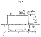
A heat assisted magnetic recording head 10 according to a first exemplary embodiment of the present invention is now described with reference to FIG. 1.
The heat assisted magnetic recording head 10 is used for perpendicular magnetic recording and includes: a magnetic recording element 18 including a recording magnetic pole 16 (see FIGS. 2 and 3) and a magnetic read element 20 for detecting a reproduction signal, these elements 18 and 20 being mounted on a floating slider 14 attached to a side face (a lower side face in FIG. 1) of a suspension 12 of HDD (which is not shown entirely in FIG. 1); a laser diode 22 serving as a light source of a heating laser beam; an irradiating optical waveguide 24 for irradiating a magnetic recording medium with the heating laser beam; and an optical waveguide 26 for directing the heating laser beam toward a rear side of the irradiating optical waveguide 24.
The irradiating optical waveguide 24 is formed by a hole (i.e., a space) or is formed from a transparent dielectric material having a dielectric constant ε of 1 or more, such as SiO2 or Al2O3. The irradiating optical waveguide 24 is arranged in the vicinity of the magnetic recording element 18 so as to allow a heating laser beam to be incident on a minute magnetizing region (described later in detail) of a magnetic recording medium 28 in which recording is performed by means of the recording magnetic pole 16.
The optical waveguide 26 is also formed from a dielectric material having a dielectric constant ε equal to or larger than 1 such as an air, SiO2, or Al2O3 like the irradiating optical waveguide 24. The optical waveguide 26 is arranged to form a mode-conversion type waveguide that converts a heating laser beam incident on an incident surface 26A located at an upper end thereof in FIG. 1 into a TM wave.
The laser diode 22 is arranged to emit laser light downward in FIG. 1 and make the emitted laser light as a heating laser beam incident on the incident surface 26A of the optical waveguide 26 through a through hole 13A formed in the suspension 12.
The laser diode 22 is supported by a side face of a heat sink 30 that is supported by the suspension 12 on an opposite side to the floating slider 14. The numeral 32 in FIG. 1 denotes a bonding wire for supplying a driving current to the laser diode 22.
The detailed structure of the heat assisted magnetic recording head 10 is described, referring to FIGS. 2 and 3.
The irradiating optical waveguide 24 is provided in the recording magnetic pole 16 that is a magnetic monopole, as shown in FIGS. 2 and 3. In a front surface (i.e., a surface seen from the magnetic recording medium 28 side; ABS surface) of the heat assisted magnetic recording head 10, a nonmagnetic layer 18A surrounds the recording magnetic pole 16 and shield layers 18B and 18C for the recording magnetic pole shield both sides of the nonmagnetic layer 18A in a vertical direction in FIGS. 2 and 3, i.e., a direction of relative movement between the heat assisted magnetic recording head 10 and the magnetic recording medium 28 (hereinafter, referred to as a relative movement direction). Moreover, an upper shied layer 21A and a lower shield layer 21B shield both sides of the magnetic read element 20 in the relative movement direction. The reference alphanumerals 11A and 11B denote a substrate and a cover layer, respectively, in FIGS. 2 and 3.
Moreover, the numeral 19 denotes a coil for forming a recording magnetic field and the numeral 27 denotes a lower cladding core serving as a buffer layer in FIG. 3.
As shown in FIG. 3, the mode-conversion type optical waveguide 26 has a flat shape in a plane that is perpendicular to top end faces of the magnetic read element 20 and the recording magnetic pole 16 and extends in a direction from the recording magnetic pole 16 toward the magnetic read element 20, i.e., the relative movement direction. The flat shape is elongate in the relative movement direction. The thickness of the optical waveguide 26 in a direction perpendicular to the relative movement direction is the same as that of the irradiating optical waveguide 24.
A tapered end face 26B is formed at a top end of the mode-conversion type optical waveguide 26 on a side close to the irradiating optical waveguide 24. The tapered end face 26B tapers toward a connection to the irradiating optical waveguide 24 in the aforementioned plane.
The optical waveguide 26 can serve as a mode-conversion type waveguide when the irradiating optical waveguide 24 has a diameter of 100 nm seen from its front side, the wavelength λ of the heating laser beam incident on the optical waveguide 26 is 700 nm, and a difference of a refractive index Δn between materials respectively forming the optical waveguide 26 and the irradiating optical waveguide 24 satisfies 0.2<Δn<0.7, for example.
A length of the optical waveguide 26 in the relative movement direction is 300 μm or more and the thickness thereof is 5 to 10 μm. The irradiating optical waveguide 24 is arranged to extend to the right in FIG. 3 so as to be in contact with a lower side of the optical waveguide 26 over a long length.
In the first exemplary embodiment, the recording magnetic pole 16 has a magnetic monopole structure for perpendicular magnetic recording that is formed from a soft magnetic metal mainly containing FeNi or FeCo. A front shape of the recording magnetic pole 16 is trapezoidal or rectangular. A thickness Pt of the recording magnetic pole 16 in the relative movement direction and a width Pw thereof in a direction perpendicular to the relative movement direction each are 20 nm or more and 200 nm or less. FIG. 4A shows a positional relationship between the irradiating optical waveguide 24 and the recording magnetic pole 16 that is a magnetic monopole. As shown in FIG. 4A, the irradiating optical waveguide 24 is arranged in the inside of a trailing edge 16D of the recording magnetic pole 16 having an approximately trapezoidal shape, when seen from a front side.
The arrangement of the irradiating optical waveguide 24 with respect to the recording magnetic pole 16 is not limited to the arrangement shown in FIG. 4A. The irradiating optical waveguide 24 may be arranged next to the trailing edge 16D, as shown in FIG. 4B. Alternatively, the irradiating optical waveguide 24 may be arranged in the inside of the trailing edge 16D of the recording magnetic pole 16, while being surrounded by a metal 25, as shown in FIG. 4C, or may be arranged next to the trailing edge 16D in the inside of the trailing edge 16D, while being surrounded by a metal 25, as shown in FIG. 4D. Alternatively, the irradiating optical waveguide 24 may be arranged next to the trailing edge 16D in the outside of the recording magnetic pole 16, as shown in FIG. 4E. In this case, the irradiating optical waveguide 24 may be arranged in a region of the floating slider 14, as shown in FIG. 4F.
The dimensions of the irradiating optical waveguide 24 shown in FIGS. 4A and 4C are described, for example. A width Gw in a width direction perpendicular to the relative movement direction and a height Gt in a thickness direction are 100 nm or less and satisfy Gw≦Pw and Gt≦Pt.
The irradiating optical waveguide 24 is arranged in one of a region located on the trailing side of a center of the recording magnetic pole 16 or the region adjacent to the trailing edge, as described above, in such a manner that the heating laser beam exiting from the irradiating optical waveguide 24 is an evanescent wave having a beam diameter of 100 nm or less and a position irradiated with the evanescent wave of a maximum power is located within ±20 to 40 nm from the trailing edge 16D in the relative movement direction.
A laser controller 34 controls the laser diode 22 to make pulse oscillation. An emission timing of the heating laser beam from the laser diode 22 is also controlled by the laser controller 34. Moreover, the laser controller 34 performs control in such a manner that a minute magnetizing region (described later) of the magnetic recording medium 28 that is to be magnetized by the recording magnetic pole 16 is irradiated with the pulsed heating laser beam in synchronization with magnetic recording performed by a magnetic recording driving circuit 36 that drives the magnetic recording element 18.
More specifically, the laser controller 34 performs control in such a manner that the minute magnetizing region is irradiated with the heating laser beam within ±3 nS from a timing at which the recording magnetic pole 16 magnetizes the minute magnetizing region when L/v<3 nS is satisfied where L is a distance between (the center of) the magnetic recording pole 16 and the irradiating optical waveguide 24 and v is a relative movement speed of the magnetic recording medium 28 in the vicinity of the recording magnetic pole 16 and the irradiating optical waveguide 24.
For example, the magnetic recording medium 28 has a structure in which an underlayer 28C of a soft magnetic material, an intermediate layer 28D of a nonmagnetic material, a recording layer 28A, a protective layer 28E, and a surface lubrication layer 28F are formed on a substrate 28B in that order, as shown in FIG. 5. In the recording layer 28A, the minute magnetizing region 29A and a nonmagnetic region 29B that is adjacent to the minute magnetizing region 29A in a direction perpendicular to the relative movement direction and has a lower thermal conductivity than the minute magnetizing region 29A are repeatedly arranged. The surfaces thereof are flush with each other.
The minute magnetizing region 29A has an anisotropic property in a thickness direction and is formed from one of a magnetic material and a magnetooptical material in which coercivity Hc lowered by temperature increase caused by irradiation with the heating laser beam is 10 kOe or less during recording. Examples of the magnetic material include CoCrPt, FePt, TbFeCo, and PtCo. Examples of the magnetooptical material include TbFeCo and DyFeCo.
Next, a process for recording information onto the magnetic recording medium 28 by the heat assisted magnetic recording head 10 is described.
The magnetic recording driving circuit 36 determines a timing at which magnetic recording is performed for the recording layer 28A of the magnetic recording medium 28 by the recording magnetic pole 16. At this timing, the laser controller 34 drives the laser diode 22 by a driving signal from the magnetic recording driving circuit 36 so as to cause pulse emission.
A pulsed heating laser beam emitted from the laser diode 22 passes through the through hole 13A in the suspension 12 and is incident on the incident surface 26A of the optical waveguide 26. The incident heating laser beam is converted into a TM wave in the optical waveguide 26 and enters the irradiating optical waveguide 24. From the irradiating optical waveguide 24, the TM mode heating laser beam exits toward the magnetic recording medium 28.
In the first exemplary embodiment, the irradiating optical waveguide 24 is configured such that the minute magnetizing region 29A of the recording layer 28A is irradiated with the laser beam prior to magnetic recording by the recording magnetic pole 16. After being heated by the irradiation of the laser beam, magnetic recording by the recording magnetic pole 16 is performed for the same minute magnetizing region 29A.
The irradiating optical waveguide 24 has a C-shape and the heating laser beam forms an elliptical or oblong beam spot BS in which a horizontal side 24A of the irradiating optical waveguide 24 is a major axis, as shown in FIG. 6A.
The major axis of the flat beam spot BS is elongate in a direction perpendicular to the relative movement direction, i.e., a width direction of a track in the case where the magnetic recording medium 28 has a rotating disc shape.
In the first exemplary embodiment, the minute magnetizing regions 29A and the nonmagnetic regions 29B are alternately formed in the recording layer 28A of the magnetic recording medium 28. When the beam spot BS is incident on one minute magnetizing region 29A, a part of the major axis of the beam spot BS is also incident on the nonmagnetic regions 29B on both sides of that minute magnetizing region 29A. However, if a length of the major axis is appropriately selected, it is possible to prevent the next minute magnetizing region 29A from being irradiated with that beam spot BS.
Therefore, it is possible to accurately irradiate a range having a minute length with the laser beam in a traveling direction of the track. When being irradiated, the minute magnetizing region 29A is efficiently heated because the nonmagnetic regions 29B having a lower thermal conductivity are located on both sides of that minute magnetizing region 29A. Thus, it is possible to make the minute magnetizing region 29A smaller so as to improve a recording density.
A timing at which magnetic recording is performed for the minute magnetizing region 29A in the recording layer by means of the recording magnetic pole 16 and a timing at which that minute magnetizing region 29A is irradiated with the heating laser beam are determined considering the distance L between the recording magnetic pole 16 and the irradiating optical waveguide 24, the relative movement speed v of the magnetic recording medium 28 with respect to the recording magnetic pole 16 and the irradiating optical waveguide 24, a power of the heating laser beam, a cooling rate of the minute magnetizing region 29A, and so on in a comprehensive manner. For example, in the case where a time required for moving of a certain minute magnetizing region 29A between the irradiating optical waveguide 24 and the magnetic recording element 18 is shorter than 3 nS, it is only necessary to irradiate the minute magnetizing region 29A with the heating laser beam within ±3 nS from the timing at which the minute magnetizing region 29A is magnetized by the recording magnetic pole 16.
When the time required for moving between the irradiating optical waveguide 24 and the recording magnetic pole 16 is 3 nS or more, it is necessary to irradiate the minute magnetizing region with the heating laser beam from the irradiating optical waveguide 24 prior to the timing at which the minute magnetizing region is magnetized by the recording magnetic pole 16.
In this case, a time difference between the magnetizing timing and the timing of the irradiation with the heating laser beam can be made larger as the power of the heating laser beam is higher.
In the heat assisted magnetic recording head 10 of the first exemplary embodiment and the heat assisted magnetic recording apparatus, the laser diode 22 is arranged on the opposite side of the suspension 12 to the floating slider 14 and the heating laser beam is directed to the irradiating optical waveguide 24 via the optical waveguide 26. Therefore, it is possible to suppress an effect of a heat generated in the laser diode 22 on the recording magnetic pole 16 or the magnetic recording element 18. Thus, the output of the laser diode 22 can be made higher.
The optical waveguide 26 is a mode-conversion type, and the heating laser beam is entirely converted into a TM mode and is then emitted from the irradiating optical waveguide 24. Thus, there is no waste of the heating laser beam. Therefore, it is possible to make the output and efficiency of the heating laser beam emitted from the irradiating optical waveguide 24 higher. Moreover, the front shape of the irradiating optical waveguide 24 is a C-shape. Therefore, the shape of the beam spot BS of the heating laser beam can be made flat and elongate in a direction perpendicular to the relative movement direction, thus making the beam spot BS smaller and achieving a higher output. Since the irradiating optical waveguide 24 is provided in a region of the recording magnetic pole 16 or a region adjacent to that region, it is possible to make the heat assisted magnetic recording head compact and make manufacturing of the heat assisted magnetic recording head easier.
In the first exemplary embodiment, the distance L between the recording magnetic pole 16 and the irradiating optical waveguide 24 and the time difference between the timing at which the minute magnetizing region 29A is magnetized by the recording magnetic pole 16 and the timing at which the same minute magnetizing region 29A is irradiated with the heating laser beam can be appropriately controlled. Therefore, it is possible to achieve high-density recording.
The irradiating optical waveguide 24 has a C-shape, as shown in FIGS. 4A to 4F or FIG. 6A in the first exemplary embodiment. However, the present invention can be configured in such a manner that, as shown in FIGS. 6B to 6F, a D-shaped irradiating optical waveguide 24B, an E-shaped irradiating optical waveguide 24C, a trapezoidal irradiating optical waveguide 24D, an irradiating optical waveguide having a modified H-shape 24E, and a L-shaped irradiating optical waveguide 24F may be employed.
In any of those cases, the major axis in the flat and elongate shape of the spot of the heating laser beam is located on the central horizontal side.
Moreover, outer corners 25 other than corners around the center of the irradiating optical waveguide 24, 24B, 24C, 24D, 24E, or 24F may be formed in an arc shape or be chamfered, as shown in FIG. 7. In this case, a convergence efficiency of an electric field can be improved.
Next, a heat assisted magnetic recording head 40 according to a second exemplary embodiment of the present invention is described with reference to FIG. 8.
The heat assisted magnetic recording head 40 has the same structure as that in the first exemplary embodiment except that in the heat assisted magnetic recording head 10 shown in FIG. 1 a heat sink 42 and a laser diode 44 supported by the heat sink 42 are arranged below the suspension 12 in FIG. 8. Therefore, in the second exemplary embodiment, the floating slider 14 is arranged below the heat sink 42 attached below the suspension 12 in FIG. 8.
It is not necessary to form a through hole for passing a heating laser beam emitted from the laser diode 44 therethrough in the suspension 12 in the heat assisted magnetic recording heed 40 of the second exemplary embodiment. Except for that, a structure, an operation, and advantages of the second exemplary embodiment are the same as those of the first exemplary embodiment. Therefore, the description thereof is omitted here.
Next, a heat assisted magnetic recording head 50 according to a third exemplary embodiment of the present invention is described with reference to FIG. 9.
The heat assisted magnetic recording head 50 is the same as the heat assisted magnetic recording head 10 of the first exemplary embodiment in that the arrangement of the suspension 12, the floating slider 14 supported below the suspension 12 in FIG. 9, the recording magnetic pole 16, the irradiating optical waveguide 24, and the optical waveguide 26, but is different in that a laser diode 52 is arranged at a base end side of the suspension 12 and a heating laser beam is directed from the laser diode 52 to the incident surface 26A of the optical waveguide 26 via a second optical waveguide 54.
More specifically, the second optical waveguide 54 is a polymer waveguide. A base end of the polymer waveguide is arranged to face a portion of the laser diode 52 from which the laser beam is emitted. A 45-degree V-shaped groove mirror 56 is formed at a top end (right end in FIG. 9) of the second optical waveguide 54.
The V-shaped groove mirror 56 is provided with a reflection film, and reflects the heating laser beam, that travels through a core 54A of the second optical waveguide 54 as the polymer waveguide to the V-shaped groove mirror 56, downward at an angle of 45 degrees, thereby making the heating laser beam incident on the incident surface 26A of the optical waveguide 26. The through hole 13A formed in the suspension 12 is arranged between the V-shaped groove mirror 56 and the incident surface 26A.
In the third exemplary embodiment, the second optical waveguide 54 largely separates the laser diode 52 from the magnetic recording element 18 and other parts. Therefore, almost all the effect of the heat from the laser diode 52 can be eliminated. Moreover, the laser diode 52 that has a relatively large mass is arranged on the base end side of the suspension 12. Therefore, mass and inertia of a top end portion including the floating slider 14 and the magnetic recording element 18 and other parts that are mounted on the floating slider 14 can be reduced, thus suppressing lowering of a floating performance of the floating slider 14.
Next, a heat assisted magnetic recording head 60 according to a fourth exemplary embodiment of the present invention is described with reference to FIG. 10.
The heat assisted magnetic recording head 60 is a ring type magnetic head for longitudinal recording. In the heat assisted magnetic recording head 60, a trailing side recording magnetic pole 62A in which a front shape is rectangular and a leading side recording magnetic pole 62B that is trimmed are provided with a recording gap 63 interposed therebetween, as shown in FIGS. 11A to 11D that are enlarged views. The numeral 64 denotes a yoke in FIG. 10.
An irradiating optical waveguide 66 is arranged in the inside of an edge of the trailing side recording magnetic pole 62A, which faces the recording gap 63, while being surrounded by a metal 67, as shown in FIG. 11A. The irradiating optical waveguide 66 may be arranged along the edge in the region of the trailing side recording magnetic pole 62A, while being surrounded by the metal 67, as shown in FIG. 11B. Moreover, without providing the metal 67 surrounding the irradiating optical waveguide 66, the irradiating optical waveguide 66 may be provided to be adjacent to the recording gap 63 in the region of the trailing side recording magnetic pole 62A, as shown in FIG. 11C, or in the region of the trailing side recording magnetic pole 62A, as shown in FIG. 1D. In the cases shown in FIGS. 11A to 11D, it is preferable to form a dielectric material first when the irradiating optical waveguide 66 is formed.
Except for the above, the structure of the heat assisted magnetic recording head 60 of the fourth exemplary embodiment is the same as the heat assisted magnetic recording head 10 shown in FIG. 3. Thus, the same parts are labeled with the same reference numerals as those in FIG. 3 and the description thereof is omitted.
Magnetic recording using the ring type heat assisted magnetic recording head 60 for longitudinal recording according to the fourth exemplary embodiment is performed for a magnetic recording medium 70 in which a continuous thin film forms a recording layer 72, as shown in FIG. 12. Except for the above, the same parts of the magnetic recording medium 70 as those in the magnetic recording medium 28 in FIG. 5 are labeled with the same reference numerals as those in FIG. 5 and the description thereof is omitted.
A manner of performing magnetic recording and an operation and advantages of heating by the heating laser beam during magnetic recording in the fourth exemplary embodiment are the same as those in the first exemplary embodiment. Therefore, the description of the magnetic recording and the heating by the heating laser beam can be omitted.

Claims (18)

1. A heat assisted magnetic recording head comprising:
a magnetic recording element including a recording magnetic pole and a magnetic read element that are mounted on a floating slider;
a laser diode serving as a light source of a heating laser beam; and
an irradiating optical waveguide, arranged close to the magnetic recording element, for directing the heating laser beam to a minute magnetizing region of a magnetic recording medium in which recording is performed by the recording magnetic pole, wherein
an optical waveguide for directing the heating laser beam to the irradiating optical waveguide is provided on a rear side of the irradiating optical waveguide;
the floating slider is supported by a surface of a suspension;
a heat sink is supported by another surface of the suspension;
the laser diode is supported by a side surface of the heat sink; and
the heating laser beam emitted from the laser diode is incident on an incident surface being located on an opposite side of the irradiating optical waveguide through a through hole formed in the suspension.
2. A magnetic recording apparatus comprising:
the heat assisted magnetic recording head according to claim 1; and
the magnetic recording medium, wherein
the magnetic recording medium includes a recording layer having an anisotropic property in a thickness direction, and the recording layer is formed from one of a magnetic material and a magnetooptical material in which coercivity Hc lowered by temperature increase caused by irradiation with the heating laser beam is 10 kOe or less during recording.
3. The magnetic recording apparatus according to claim 2, wherein:
the magnetic recording medium includes a plurality of layers, and in at least one of the plurality of layers, at least a region that is adjacent to the minute magnetizing region or an overlapping region overlapping the minute magnetizing region in the thickness direction in a direction perpendicular to a relative movement direction of the magnetic recording medium with respect to the recording magnetic pole is formed from a nonmagnetic layer having a lower thermal conductivity than that of the minute magnetizing region or the overlapping region.
4. A magnetic recording apparatus comprising:
the heat assisted magnetic recording head according to claim 1; and
the magnetic recording medium, wherein
the magnetic recording medium includes a recording layer having an anisotropic property in a relative movement direction of the magnetic recording medium with respect to the recording magnetic pole, and the recording layer is formed from a magnetic material in which coercivity Hc lowered by temperature increase caused by irradiation with the heating laser beam is 8 kOe or less during recording.
5. The magnetic recording apparatus according to claim 4, wherein:
the magnetic recording medium includes a plurality of layers, and in at least one of the plurality of layers, at least a region that is adjacent to the minute magnetizing region or an overlapping region overlapping the minute magnetizing region in the thickness direction in a direction perpendicular to a relative movement direction of the magnetic recording medium with respect to the recording magnetic pole is formed from a nonmagnetic layer having a lower thermal conductivity than that of the minute magnetizing region or the overlapping region.
6. A heat assisted magnetic recording head comprising:
a magnetic recording element including a recording magnetic pole and a magnetic read element that are mounted on a floating slider;
a laser diode serving as a light source of a heating laser beam; and
an irradiating optical waveguide, arranged close to the magnetic recording element, for directing the heating laser beam to a minute magnetizing region of a magnetic recording medium in which recording is performed by the recording magnetic pole, wherein
an optical waveguide for directing the heating laser beam to the irradiating optical waveguide is provided on a rear side of the irradiating optical waveguide;
the floating slider is supported by a surface of a suspension;
the laser diode is attached on a rear side of the floating slider in such a manner that the heating laser beam emitted from the laser diode is incident on an incident surface of the optical waveguide, the incident surface being located on an opposite side to the irradiating optical waveguide; and
a second optical waveguide is provided on another surface of the suspension, the second optical waveguide being optically connected to the incident surface of the optical waveguide at its top end and to a surface of the laser diode from which the heating laser beam is emitted, at its base end.
7. The heat assisted magnetic recording head according to claim 6, wherein the top end of the second optical waveguide is optically connected to the incident surface of the optical waveguide via a V-shaped groove mirror that is provided on the other surface of the suspension.
8. The heat assisted magnetic recording head according to claim 6, wherein the second optical waveguide is a polymer waveguide.
9. A heat assisted magnetic recording head comprising:
a magnetic recording element including a recording magnetic pole and a magnetic read element that are mounted on a floating slider;
a laser diode serving as a light source of a heating laser beam: and
an irradiating optical waveguide, arranged close to the magnetic recording element, for directing the heating laser beam to a minute magnetizing region of a magnetic recoding medium in which recording is performed by the recording magnetic pole, wherein
an optical waveguide for directing the heating laser beam to the irradiating optical waveguide is provided on a rear side of the irradiating optical waveguide;
the irradiating optical waveguide is formed from a dielectric material having a dielectric constant ε of 1 or more, the dielectric material including air;
a front shape of the irradiating optical waveguide is one of a C-shape, a D-shape, an E-shape, a trapezoidal shape, a modified H-shape, and an L-shape; and
the irradiating optical waveguide is configured in such a manner that the heating laser beam is emitted along a long side extending in a direction perpendicular to a relative movement direction of the recording magnetic pole and a recording medium with respect to each other, and the heating laser beam is flat in the direction.
10. A heat assisted magnetic recording head comprising:
a magnetic recording element including a recording magnetic pole and a magnetic read element that are mounted on a floating slider;
a laser diode serving as a light source of a heating laser beam; and
an irradiating optical waveguide, arranged close to the magnetic recording element, for directing the heating laser beam to a minute magnetizing region of a magnetic recoding medium in which recording is performed by the recording magnetic pole, wherein
an optical waveguide for directing the heating laser beam to the irradiating optical waveguide is provided on a rear side of the irradiating optical waveguide;
the recording magnetic pole has a magnetic monopole structure for perpendicular magnetic recording, the pole being formed from a soft magnetic metal;
the recording magnetic pole is isolated by shields for the recording magnetic pole arranged on both sides of the recording magnetic pole in a thickness direction that is a relative movement direction of the recording magnetic pole with respect to a magnetic recording medium;
a front shape of the recording magnetic pole is trapezoidal or rectangular; and
a thickness Pt of the recording magnetic pole in the thickness direction and a width Pw thereof in a width direction perpendicular to the thickness direction are 20 nm or more and 200 nm or less.
11. The heat assisted magnetic recording head according to claim 10, wherein a width Gw of the irradiating optical waveguide in the width direction and a height Gt thereof in the thickness direction each are 100 nm or less and satisfy Gw ≦ Pw and Gt ≦ Pt.
12. The heat assisted magnetic recording head according to claim 11, wherein: the irradiating optical waveguide is arranged in one of a region located on a trailing side of a center of the recording magnetic pole and a region adjacent to a trailing edge of the recording magnetic pole in such a manner that the heating laser beam exiting from the irradiating optical waveguide is an evanescent wave having a beam diameter of 100 nm or less and a position irradiated with the evanescent wave of a maximum power is located within +20 to 40 nm from the trailing edge in the relative movement direction.
13. heat assisted magnetic recording head comprising:
a magnetic recording element including a recording magnetic pole and a magnetic read element that are mounted on a floating slider;
a laser diode serving as a light source of a heating laser beam; and
an irradiating optical waveguide, arranged close to the magnetic recording element, for directing the heating laser beam to a minute magnetizing region of a magnetic recoding medium in which recording is performed by the recording magnetic pole, wherein
an optical waveguide for directing the heating laser beam to the irradiating optical waveguide is provided on a rear side of the irradiating optical waveguide;
the recording magnetic pole is formed from a soft magnetic metal and has a ring structure for longitudinal recording that includes a trailing side recording magnetic pole and a leading side recording magnetic pole, the leading recording magnetic pole being trimmed;
a front shape of the trailing side recording magnetic pole is rectangular; and
a thickness Pt of the recording magnetic pole in a thickness direction and a width Pw thereof in a width direction perpendicular to the thickness direction each are 200 nm or less, the thickness direction being a relative movement direction of the recording magnetic pole with respect to the magnetic recording medium.
14. The heat assisted magnetic recording head according to claim 13, Wherein: a width Gw of the irradiating optical waveguide in the width direction and a height Gt thereof in the thickness direction each are 100 nm or less and satisfy Gw ≦ Pw and Gt ≦ Pt.
15. The heat assisted magnetic recording head according to claim 13, wherein: the irradiating optical waveguide is arranged in one of a region located on a trailing side of a center of the recording magnetic pole and a region adjacent to a trailing edge of the recording magnetic pole in such a manner that the heating laser beam exiting from the irradiating optical waveguide is an evanescent wave having a beam diameter of 100 nm or less and a position irradiated with the evanescent wave of a maximum power is within +20 to 40 nm from the trailing edge in the relative movement direction.
16. A heat assisted magnetic recording head comprising:
a magnetic recording element including a recording magnetic pole and a magnetic read element that are mounted on a floating slider;
a laser diode serving as a light source of a heating laser beam; and
a laser controller for controlling a timing of emission of the heating laser beam by the laser diode,
an irradiating optical waveguide, arranged close to the magnetic recording element, for directing the heating laser beam to a minute magnetizing region of a magnetic recoding medium in which recording is performed by the recording magnetic pole, wherein
an optical waveguide for directing the heating laser beam to the irradiating optical waveguide is provided on a rear side of the irradiating optical waveguide; and
the laser controller performs control in such a manner that the minute magnetizing region is irradiated with the heating laser beam within +3 nS from a timing at which the minute magnetizing region is magnetized by the recording magnetic pole when L/v <3 nS, where L is a distance between the recording magnetic pole and the magnetic read element and v is a relative movement speed of the magnetic recoding medium with respect to the recording magnetic pole and the magnetic read element in a vicinity of the recording magnetic pole and the magnetic read element.
17. The heat assisted magnetic recording head according to claim 16, wherein the laser controller is arranged to control the laser diode to make pulse oscillation in synchronization with the recording magnetic pole.
18. A heat assisted magnetic recording head comprising:
a magnetic recording element including a recording magnetic pole and a magnetic read element that are mounted on a floating slider;
a laser diode serving as a light source of a heating laser beam; and
a laser controller for controlling a timing of emission of the heating laser beam by the laser diode,
an irradiating optical waveguide, arranged close to the magnetic recording element, for directing the heating laser beam to a minute magnetizing region of a magnetic recoding medium in which recording is performed by the recording magnetic pole, wherein
an optical waveguide for directing the heating laser beam to the irradiating optical waveguide is provided on a rear side of the irradiating optical waveguide; and
the laser controller performs control in such a manner that the minute magnetizing region is irradiated with the heating laser beam prior to a timing at which the minute magnetizing region is magnetized by the recording magnetic pole when L/v ≧ 3 nS, where L is a distance between the recording magnetic pole and the magnetic read element and v is a relative movement speed of the magnetic recording medium with respect to the recording magnetic pole and the magnetic read element in a vicinity of the recording magnetic pole and the magnetic read element.
US11/319,164 2004-12-28 2005-12-28 Heat assisted magnetic recording head and heat assisted magnetic recording apparatus for heating a recording region in a magnetic recording medium during magnetic recording Active 2027-07-20 US7538978B2 (en)

Applications Claiming Priority (2)

Application Number Priority Date Filing Date Title
JP2004380527A JP4635607B2 (en) 2004-12-28 2004-12-28 Thermally assisted magnetic recording head and thermally assisted magnetic recording apparatus
JP2004-380527 2004-12-28

Publications (2)

Publication Number Publication Date
US20060187564A1 US20060187564A1 (en) 2006-08-24
US7538978B2 true US7538978B2 (en) 2009-05-26

Family

ID=36738535

Family Applications (1)

Application Number Title Priority Date Filing Date
US11/319,164 Active 2027-07-20 US7538978B2 (en) 2004-12-28 2005-12-28 Heat assisted magnetic recording head and heat assisted magnetic recording apparatus for heating a recording region in a magnetic recording medium during magnetic recording

Country Status (2)

Country Link
US (1) US7538978B2 (en)
JP (1) JP4635607B2 (en)

Cited By (49)

* Cited by examiner, † Cited by third party
Publication number Priority date Publication date Assignee Title
US20080055784A1 (en) * 2006-08-31 2008-03-06 Tdk Corporation Thermally assisted magnetic head
US20080055762A1 (en) * 2006-08-31 2008-03-06 Tdk Corporation Thermally assisted magnetic head, head gimbal assembly, and hard disk drive
US20080192376A1 (en) * 2006-08-31 2008-08-14 Tdk Corporation Thermally assisted magnetic head
US20090052076A1 (en) * 2007-08-23 2009-02-26 Tdk Corporation Thermally assisted magnetic head with optical waveguide
US20090052077A1 (en) * 2007-08-23 2009-02-26 Tdk Corporation Thermally assisted magnetic head with optical waveguide and light shield
US20090116804A1 (en) * 2007-11-05 2009-05-07 Seagate Technology Llc Integrated Device For Heat Assisted Magnetic Recording
US20100163521A1 (en) * 2008-12-30 2010-07-01 Hitachi Global Storage Technologies Netherlands Bv System, method and apparatus for fabricating a c-aperture or e-antenna plasmonic near field source for thermal assisted recording applications
US20100315736A1 (en) * 2009-06-11 2010-12-16 Tdk Corporation Multilayered Waveguide Having Protruded Light-Emitting End
US20110122737A1 (en) * 2009-11-20 2011-05-26 Tdk Corporation Thermally-Assisted Magnetic Recording Head with Light Detector in Element-Integration Surface
US20110128827A1 (en) * 2009-12-01 2011-06-02 Tdk Corporation Light source unit for thermally-assisted magnetic recording
US20110149698A1 (en) * 2008-06-02 2011-06-23 Hitachi, Ltd. Thermally assisted magnetic recording head and head assembly
US20110157738A1 (en) * 2009-12-28 2011-06-30 Tdk Corporation Method for manufacturing thermally-assisted magnetic recording head by semi-active alignment
US20110228653A1 (en) * 2010-03-22 2011-09-22 Tdk Corporation Light source unit for thermally-assisted magnetic recording capable of monitoring of light output
US20110228416A1 (en) * 2010-03-17 2011-09-22 Headway Technologies, Inc. A method of manufacturing a thermally assisted magnetic head
US20110228650A1 (en) * 2010-03-18 2011-09-22 Tdk Corporation Method for manufacturing thermally-assisted magnetic recording head comprising light source unit and slider
US20110228652A1 (en) * 2010-03-19 2011-09-22 Edward Charles Gage Slider For Heat Assisted Magnetic Recording Including A Photo Detector For Monitoring Laser Power
US20110228649A1 (en) * 2010-03-18 2011-09-22 Tdk Corporation Method for manufacturing thermally-assisted magnetic recording head comprising light source unit and slider
US20120099407A1 (en) * 2010-10-20 2012-04-26 Seagate Technology Llc Method and apparatus for coupling a laser diode to a magnetic writer
US8240025B2 (en) 2010-09-23 2012-08-14 Tdk Corporation Method for manufacturing head including light source unit for thermal assist
US8248892B2 (en) 2010-08-20 2012-08-21 Tdk Corporation Head gimbal assembly with two wiring layers comprising thermally-assisted head
US8250737B2 (en) 2010-10-14 2012-08-28 Tdk Corporation Method for manufacturing head including light source unit for thermal assist
US8274867B2 (en) 2010-03-31 2012-09-25 Tdk Corporation Method for aligning the light source unit and the slider of thermally-assisted magnetic recording head
US8289821B1 (en) 2010-12-21 2012-10-16 Western Digital (Fremont), Llc Method and system for pulsing EAMR disk drives
US8351151B2 (en) 2010-11-02 2013-01-08 Hitachi Global Storage Technologies Netherlands B.V. Thermally assisted magnetic write head employing a near field transducer (NFT) having a diffusion barrier layer between the near field transducer and a magnetic lip
US8384405B2 (en) 2011-04-20 2013-02-26 Tdk Corporation Method for performing burn-in test
US8406091B2 (en) 2010-07-08 2013-03-26 Tdk Corporation Thermal assisted magnetic recording head having integral mounted of photo-detector and laser diode
US8411535B1 (en) 2011-11-30 2013-04-02 HGST Netherlands B.V. Electrical connection for a laser diode in a tar head
US8437237B2 (en) 2011-01-07 2013-05-07 Tdk Corporation Light source unit including a photodetector, and thermally-assisted magnetic recording head
US8472287B1 (en) 2012-02-22 2013-06-25 Tdk Corporation Thermally-assisted magnetic recording head having a groove for inserting into suspension
US20130230279A1 (en) * 2009-11-05 2013-09-05 Seagate Technology Llc Light delivery waveguide
US8631561B2 (en) 2011-11-30 2014-01-21 HGST Netherlands B.V. Method for electrically connecting an energy source to a head of a disk drive
US8654617B2 (en) 2012-03-21 2014-02-18 Tdk Corporation Thermally-assisted magnetic recording head with optically isolating waveguide, head gimbal assembly, head arm assembly, magnetic disk unit, and light transmission unit
US8891341B1 (en) 2013-03-11 2014-11-18 Western Digital Technologies, Inc. Energy assisted magnetic recording disk drive using modulated laser light
US8908480B1 (en) 2012-09-28 2014-12-09 Western Digital Technologies, Inc. Method and system for providing an energy assisted magnetic recording disk drive using a pulsed laser light
US8957692B2 (en) 2010-12-02 2015-02-17 Tdk Corporation Method for performing burn-in test
US8997832B1 (en) 2010-11-23 2015-04-07 Western Digital (Fremont), Llc Method of fabricating micrometer scale components
US9064525B2 (en) 2013-11-26 2015-06-23 Western Digital Technologies, Inc. Disk drive comprising laser transmission line optimized for heat assisted magnetic recording
US9065236B2 (en) 2010-04-30 2015-06-23 Seagate Technology Method and apparatus for aligning a laser diode on a slider
US9202499B2 (en) 2013-03-13 2015-12-01 Seagate Technology Llc Contact detection using laser modulation
US9218836B2 (en) 2014-02-28 2015-12-22 Seagate Technology Llc Heat assisted magnetic recording head having dual waveguides
US9245573B2 (en) 2013-06-24 2016-01-26 Seagate Technology Llc Methods of forming materials for at least a portion of a NFT and NFTs formed using the same
US9318142B2 (en) 2012-04-25 2016-04-19 Seagate Technology Llc Laser modulation for magnetic recording apparatus
US9502070B2 (en) 2013-06-24 2016-11-22 Seagate Technology Llc Materials for near field transducers, near field tranducers containing same, and methods of forming
US9570098B2 (en) 2013-12-06 2017-02-14 Seagate Technology Llc Methods of forming near field transducers and near field transducers formed thereby
US9697856B2 (en) 2013-12-06 2017-07-04 Seagate Techology LLC Methods of forming near field transducers and near field transducers formed thereby
US9805757B2 (en) 2010-02-23 2017-10-31 Seagate Technology Llc HAMR NFT materials with improved thermal stability
US9822444B2 (en) 2014-11-11 2017-11-21 Seagate Technology Llc Near-field transducer having secondary atom higher concentration at bottom of the peg
US10510364B2 (en) 2014-11-12 2019-12-17 Seagate Technology Llc Devices including a near field transducer (NFT) with nanoparticles
US11749302B1 (en) * 2022-05-12 2023-09-05 Sae Magnetics (H.K.) Ltd. Method of manufacturing head gimbal assembly, head gimbal assembly and hard disk drive

Families Citing this family (86)

* Cited by examiner, † Cited by third party
Publication number Priority date Publication date Assignee Title
JP4317119B2 (en) * 2004-11-30 2009-08-19 富士通株式会社 Thermally assisted magnetic recording method and test recording / reproducing method
JP2007134004A (en) * 2005-11-14 2007-05-31 Fujitsu Ltd Heat assisted magnetic recording medium and heat assisted magnetic recording device
JP2008047268A (en) 2006-08-21 2008-02-28 Tdk Corp Thermally assisted magnetic head
JP2008059695A (en) 2006-08-31 2008-03-13 Tdk Corp Heat assisted magnetic head, head gimbal assembly, and hard disk drive
KR100803215B1 (en) * 2006-08-31 2008-02-14 삼성전자주식회사 Metal layer having aperture, method of forming the same, light delivery module comprising metal layer having aperture and heat assisted magnetic recording head comprising the same
KR100851973B1 (en) * 2006-11-02 2008-08-12 삼성전자주식회사 waveguide, method of fabricating the same, light delivery module employing the waveguide and heat assisted magnetic recording head employing the bending waveguide
JP4782660B2 (en) * 2006-11-21 2011-09-28 株式会社日立製作所 Head, head gimbal assembly and information recording apparatus
CN101578660A (en) * 2006-12-27 2009-11-11 富士通株式会社 Head suspension assembly, carriage assembly and method for manufacturing head slider assembly
JP2008165922A (en) 2006-12-28 2008-07-17 Tdk Corp Heat assisted magnetic head, head gimbal assembly, and hard disk drive
KR100842898B1 (en) * 2007-01-29 2008-07-03 삼성전자주식회사 Structure for light coupling in heat assisted magnetic recording
JP4364912B2 (en) 2007-02-26 2009-11-18 Tdk株式会社 Thermally assisted magnetic head, head gimbal assembly, and hard disk drive
KR100846515B1 (en) * 2007-03-19 2008-07-17 삼성전자주식회사 90° bent metallic waveguide having tapered c-shaped aperture, method of fabricating the same, light delivery module employing the waveguide and heat assisted magnetic recording head employing the bending waveguide
JP4539672B2 (en) * 2007-03-27 2010-09-08 Tdk株式会社 Thermally assisted magnetic head, head gimbal assembly, and hard disk drive
JP5085988B2 (en) * 2007-06-21 2012-11-28 株式会社日立製作所 Manufacturing method of optical element integrated head
JP4552983B2 (en) 2007-08-10 2010-09-29 Tdk株式会社 Thermally assisted magnetic head, head gimbal assembly, and hard disk drive
JP4450032B2 (en) 2007-08-23 2010-04-14 Tdk株式会社 Thermally assisted magnetic head, head gimbal assembly, and hard disk drive
JP2009054867A (en) 2007-08-28 2009-03-12 Tdk Corp Semiconductor laser element structure, and thermal assist magnetic head, and manufacturing method thereof
JP5134310B2 (en) * 2007-08-31 2013-01-30 エイチジーエスティーネザーランドビーブイ Magnetic head slider
US8289650B2 (en) * 2007-09-19 2012-10-16 Seagate Technology Llc HAMR recording head having a sloped wall pole
JP4497201B2 (en) 2007-12-28 2010-07-07 Tdk株式会社 Manufacturing method of heat-assisted magnetic head
JP4462346B2 (en) 2007-12-28 2010-05-12 Tdk株式会社 Thermally assisted magnetic head
JP4836966B2 (en) 2008-01-18 2011-12-14 株式会社日立製作所 Head gimbal assembly and information recording apparatus
JP4518158B2 (en) 2008-02-08 2010-08-04 Tdk株式会社 Thermally assisted magnetic head, head gimbal assembly, and hard disk drive
US8677607B2 (en) 2008-03-07 2014-03-25 Tdk Corporation Method of manufacturing magnetoresistive element
US7986592B2 (en) * 2008-03-10 2011-07-26 Hitachi Global Storage Technologies, Netherlands B.V. Components and assembly procedure for thermal assisted recording
JP2009230812A (en) * 2008-03-24 2009-10-08 Furukawa Electric Co Ltd:The Glass base and heat assist magnetic recording disk
US20090258186A1 (en) * 2008-04-10 2009-10-15 Hitachi Global Storage Technologies Netherlands B. V. Wafer-level method for fabricating an optical channel and aperture structure in magnetic recording head sliders for use in thermally-assisted recording (tar)
US8243388B2 (en) * 2008-04-22 2012-08-14 Tdk Corporation Heat-assisted magnetic head constituted of slider and light source unit, and manufacturing method of the head
US8065786B2 (en) * 2008-04-23 2011-11-29 Tdk Corporation Manufacturing method of heat-assisted magnetic head constituted of slider and light source unit
JP4928499B2 (en) 2008-05-14 2012-05-09 日東電工株式会社 Suspension board with circuit
JP5017184B2 (en) 2008-06-10 2012-09-05 株式会社日立製作所 Thermally assisted magnetic recording head
JP2009301619A (en) 2008-06-11 2009-12-24 Nitto Denko Corp Suspension substrate with circuit and producing method thereof
JP2009301620A (en) 2008-06-11 2009-12-24 Nitto Denko Corp Suspension substrate with circuit
DE102008028070A1 (en) * 2008-06-12 2009-12-17 Bayer Technology Services Gmbh Catalyst and process for the hydrogenation of organic compounds
JP2010015618A (en) 2008-07-01 2010-01-21 Nitto Denko Corp Suspension board with circuit, and method for manufacturing the same
JP2010015641A (en) * 2008-07-04 2010-01-21 Nitto Denko Corp Suspension board with circuit, and manufacturing method thereof
JP4989572B2 (en) 2008-07-07 2012-08-01 日東電工株式会社 Suspension board with circuit and manufacturing method thereof
JP5150403B2 (en) 2008-08-06 2013-02-20 株式会社日立製作所 Thermally assisted magnetic recording head
JP5330757B2 (en) * 2008-08-06 2013-10-30 エイチジーエスティーネザーランドビーブイ Magnetic recording method and magnetic recording apparatus
US7852587B2 (en) * 2008-09-11 2010-12-14 Hitachi Global Storage Technologies Netherlands B.V. Thermal assisted recording (TAR) disk drive capable of controlling the write pulses
US7821732B2 (en) 2008-09-25 2010-10-26 Tdk Corporation Thermally assisted magnetic head having an asymmetric plasmon antenna and manufacturing method thereof
US8335052B2 (en) 2008-09-25 2012-12-18 Tdk Corporation Plasmon antenna for thermally assisted magnetic head
US7924658B2 (en) * 2008-10-06 2011-04-12 Tdk Corporation Heat-assisted magnetic recording head constituted of slider and light source unit, and manufacturing method of the head
US8018685B2 (en) * 2008-10-16 2011-09-13 Tdk Corporation Head gimbal assembly for heat-assisted magnetic recording
JP5138549B2 (en) 2008-10-31 2013-02-06 日東電工株式会社 Suspension board with circuit
US7936531B2 (en) 2008-11-07 2011-05-03 Tdk Corporation Thermally assisted magnetic head having an asymmetric plasmon antenna and manufacturing method thereof
JP5002574B2 (en) 2008-11-11 2012-08-15 日東電工株式会社 Suspension board with circuit and manufacturing method thereof
JP4951609B2 (en) 2008-11-11 2012-06-13 日東電工株式会社 Suspension board with circuit
US7880996B2 (en) 2008-12-31 2011-02-01 Hitachi Global Storage Technologies Netherlands B.V. Ridge wave-guide for thermal assisted magnetic recording
US8472286B2 (en) * 2008-12-31 2013-06-25 HGST Netherlands B.V. Near field transducer having main body and wings extending therefrom and only electrically coupled thereby
JP2010160867A (en) * 2009-01-09 2010-07-22 Fujitsu Ltd Magnetic recording and reproducing device, magnetic recording medium, and method of manufacturing magnetic recording medium
JP5204679B2 (en) 2009-01-23 2013-06-05 日東電工株式会社 Suspension board with circuit
US8000175B2 (en) 2009-01-30 2011-08-16 Tdk Corporation Thermally assisted magnetic head having a semiconductor surface-emitting laser
US7936643B2 (en) 2009-02-03 2011-05-03 Tdk Corporation Thermal assisted magnetic recording head having surface-emitting semiconductor laser
US8116172B2 (en) 2009-02-09 2012-02-14 Tdk Corporation Near-field light generating device including surface plasmon generating element
US7898909B2 (en) 2009-02-12 2011-03-01 Tdk Corporation Thermal-assisted magnetic recording head having substrate and light reflection section
JP5361474B2 (en) * 2009-03-17 2013-12-04 エイチジーエスティーネザーランドビーブイ Head gimbal assembly and disk drive
US8325566B2 (en) * 2009-03-19 2012-12-04 Tdk Corporation Thermally-assisted magnetic recording head having a light source at least inclined from an opposed-to-medium surface
US8233358B2 (en) * 2009-06-15 2012-07-31 Headway Technologies, Inc. Plasmon antenna with magnetic core for thermally assisted magnetic recording
US8254212B2 (en) * 2009-06-25 2012-08-28 Seagate Technology Llc Integrated heat assisted magnetic recording device
US8194509B2 (en) * 2009-07-30 2012-06-05 Tdk Corporation Thermally-assisted magnetic recording head comprising light source with photonic-band layer
JP5515703B2 (en) * 2009-09-18 2014-06-11 ソニー株式会社 Thermally assisted magnetic head and information recording apparatus
JP5204738B2 (en) 2009-10-16 2013-06-05 日東電工株式会社 Suspension board with circuit and manufacturing method thereof
US8031561B2 (en) * 2009-10-28 2011-10-04 Hitachi Global Storage Technologies Netherlands B.V. Joint design of thermally-assisted magnetic recording head and patterned media for high optical efficiency
JP5322898B2 (en) * 2009-11-25 2013-10-23 株式会社日立製作所 Thermally assisted magnetic head slider and head gimbal assembly
JP5227940B2 (en) 2009-11-26 2013-07-03 日東電工株式会社 Suspension board with circuit
US8532157B2 (en) 2010-02-23 2013-09-10 Seagate Technology Llc Capping method for laser diode protection
US8345517B2 (en) * 2010-04-30 2013-01-01 Seagate Technology Llc Method and apparatus for aligning a laser diode on a slider
US8179628B2 (en) * 2010-07-08 2012-05-15 Headway Technologies, Inc. Magnetic core plasmon antenna with improved coupling efficiency
US9053731B2 (en) * 2010-07-09 2015-06-09 HGST Netherlands B.V. Extended cavity VCSEL mounted to substrate with electrical and thermal contact to substrate and optical power directed toward substrate
JP5439316B2 (en) * 2010-08-30 2014-03-12 株式会社日立製作所 Thermally assisted recording head and magnetic recording apparatus
US8339739B2 (en) * 2010-08-31 2012-12-25 Hitachi Global Storage Technologies Netherlands B.V. Thermally assisted recording head with near field transducer having integral heatsink
US8107326B1 (en) 2010-11-15 2012-01-31 Hitachi Global Storage Technologies Netherlands B.V. Slider with integrated thermally-assisted recording (TAR) head and integrated long laser diode
JP5323802B2 (en) 2010-12-13 2013-10-23 ローム株式会社 Semiconductor laser element
US8139448B1 (en) 2010-12-15 2012-03-20 Hitachi Global Storage Technologies Netherlands B.V. Slider with integrated thermally-assisted recording (TAR) head and vertical-cavity surface-emitting laser (VCSEL) with angled external cavity
US8184507B1 (en) 2010-12-15 2012-05-22 Hitachi Global Storage Technologies Netherlands B.V. Slider with integrated thermally-assisted recording (TAR) head and long laser diode with optical body for directing laser radiation
JP5323879B2 (en) 2011-01-27 2013-10-23 ローム株式会社 Semiconductor laser element
JP5966296B2 (en) * 2011-09-27 2016-08-10 大日本印刷株式会社 Flexure substrate for suspension, suspension, suspension with head, and hard disk drive
US8787126B2 (en) * 2011-10-10 2014-07-22 Seagate Technology Llc Waveguide with blocking layer
JP2013097819A (en) 2011-10-27 2013-05-20 Hitachi Ltd Apparatus and method for inspecting thermally assisted magnetic head
US8750081B1 (en) 2012-12-20 2014-06-10 Seagate Technology Llc Light delivery
JP6084305B2 (en) 2013-01-31 2017-02-22 ヒューレット パッカード エンタープライズ デベロップメント エル ピーHewlett Packard Enterprise Development LP Magnetic tape processing
US8971159B2 (en) 2013-05-08 2015-03-03 Seagate Technology Llc Light delivery apparatus
US20160300592A1 (en) * 2013-10-17 2016-10-13 Sharp Kabushiki Kaisha Heat-assisted-magnetic-recording head, semiconductor laser element, and method for manufacturing semiconductor laser element
JP6123843B2 (en) * 2015-05-21 2017-05-10 大日本印刷株式会社 Flexure substrate for suspension, suspension, suspension with head, and hard disk drive
US10629236B1 (en) * 2018-11-12 2020-04-21 Western Digital Technologies, Inc. Slider gas-bearing surface designs to mitigate effects of smear in heat-assisted magnetic recording

Citations (6)

* Cited by examiner, † Cited by third party
Publication number Priority date Publication date Assignee Title
JP2665022B2 (en) 1990-06-13 1997-10-22 シャープ株式会社 Magnetic head and method of manufacturing the same
US20030128452A1 (en) * 2002-01-07 2003-07-10 Seagate Technology Llc Write head and method for recording information on a data storage medium
JP3441417B2 (en) 2000-03-30 2003-09-02 株式会社東芝 Magnetic recording head and magnetic recording device using the same
JP3471285B2 (en) 2000-03-30 2003-12-02 株式会社東芝 Thermally assisted magnetic recording head and thermally assisted magnetic recording device
US20040001420A1 (en) * 2002-06-28 2004-01-01 Seagate Technology Llc Heat assisted magnetic recording head with a planar waveguide
US20050135008A1 (en) * 2003-09-05 2005-06-23 Seagate Technology Llc Diffraction grating

Family Cites Families (3)

* Cited by examiner, † Cited by third party
Publication number Priority date Publication date Assignee Title
JP3492270B2 (en) * 2000-01-31 2004-02-03 株式会社東芝 Thermally assisted magnetic recording head and thermally assisted magnetic recording apparatus
JP3903365B2 (en) * 2001-03-29 2007-04-11 株式会社東芝 Optically assisted magnetic recording head and optically assisted magnetic recording apparatus
JP2003045004A (en) * 2001-07-27 2003-02-14 Fuji Xerox Co Ltd Optical assist magnetic head and optical assist magnetic disk device

Patent Citations (7)

* Cited by examiner, † Cited by third party
Publication number Priority date Publication date Assignee Title
JP2665022B2 (en) 1990-06-13 1997-10-22 シャープ株式会社 Magnetic head and method of manufacturing the same
JP3441417B2 (en) 2000-03-30 2003-09-02 株式会社東芝 Magnetic recording head and magnetic recording device using the same
JP3471285B2 (en) 2000-03-30 2003-12-02 株式会社東芝 Thermally assisted magnetic recording head and thermally assisted magnetic recording device
US20030128452A1 (en) * 2002-01-07 2003-07-10 Seagate Technology Llc Write head and method for recording information on a data storage medium
US6714370B2 (en) * 2002-01-07 2004-03-30 Seagate Technology Llc Write head and method for recording information on a data storage medium
US20040001420A1 (en) * 2002-06-28 2004-01-01 Seagate Technology Llc Heat assisted magnetic recording head with a planar waveguide
US20050135008A1 (en) * 2003-09-05 2005-06-23 Seagate Technology Llc Diffraction grating

Cited By (84)

* Cited by examiner, † Cited by third party
Publication number Priority date Publication date Assignee Title
US20080055784A1 (en) * 2006-08-31 2008-03-06 Tdk Corporation Thermally assisted magnetic head
US20080055762A1 (en) * 2006-08-31 2008-03-06 Tdk Corporation Thermally assisted magnetic head, head gimbal assembly, and hard disk drive
US20080192376A1 (en) * 2006-08-31 2008-08-14 Tdk Corporation Thermally assisted magnetic head
US7974043B2 (en) * 2006-08-31 2011-07-05 Tdk Corporation Thermally assisted magnetic head
US7940486B2 (en) * 2006-08-31 2011-05-10 Tdk Corporation Thermally assisted magnetic head, head gimbal assembly, and hard disk drive
US20090052076A1 (en) * 2007-08-23 2009-02-26 Tdk Corporation Thermally assisted magnetic head with optical waveguide
US20090052077A1 (en) * 2007-08-23 2009-02-26 Tdk Corporation Thermally assisted magnetic head with optical waveguide and light shield
US8023225B2 (en) * 2007-08-23 2011-09-20 Tdk Corporation Thermally assisted magnetic head with optical waveguide
US7957099B2 (en) * 2007-08-23 2011-06-07 Tdk Corporation Thermally assisted magnetic head with optical waveguide and light shield
US7706654B2 (en) * 2007-11-05 2010-04-27 Seagate Technology Llc Integrated device for heat assisted magnetic recording
US20090116804A1 (en) * 2007-11-05 2009-05-07 Seagate Technology Llc Integrated Device For Heat Assisted Magnetic Recording
US8270262B2 (en) 2008-06-02 2012-09-18 Hitachi, Ltd. Thermally assisted magnetic recording head and head assembly
US20110149698A1 (en) * 2008-06-02 2011-06-23 Hitachi, Ltd. Thermally assisted magnetic recording head and head assembly
US8486289B2 (en) * 2008-12-30 2013-07-16 HGST Netherlands B.V. System, method and apparatus for fabricating a C-aperture or E-antenna plasmonic near field source for thermal assisted recording applications
US20100163521A1 (en) * 2008-12-30 2010-07-01 Hitachi Global Storage Technologies Netherlands Bv System, method and apparatus for fabricating a c-aperture or e-antenna plasmonic near field source for thermal assisted recording applications
US20120070784A1 (en) * 2008-12-30 2012-03-22 Hitachi Global Storage Technologies Netherlands B.V. System, method and apparatus for fabricating a c-aperture or e-antenna plasmonic near field source for thermal assisted recording applications
US8092704B2 (en) * 2008-12-30 2012-01-10 Hitachi Global Storage Technologies Netherlands B.V. System, method and apparatus for fabricating a c-aperture or E-antenna plasmonic near field source for thermal assisted recording applications
US20100315736A1 (en) * 2009-06-11 2010-12-16 Tdk Corporation Multilayered Waveguide Having Protruded Light-Emitting End
US8213272B2 (en) * 2009-06-11 2012-07-03 Tdk Corporation Multilayered waveguide having protruded light-emitting end
US8730780B2 (en) * 2009-11-05 2014-05-20 Seagate Technology Light delivery waveguide
US20130230279A1 (en) * 2009-11-05 2013-09-05 Seagate Technology Llc Light delivery waveguide
US8441895B2 (en) 2009-11-20 2013-05-14 Tdk Corporation Thermally-assisted magnetic recording head with light detector in element-integration surface
US20110122737A1 (en) * 2009-11-20 2011-05-26 Tdk Corporation Thermally-Assisted Magnetic Recording Head with Light Detector in Element-Integration Surface
US8254214B2 (en) 2009-12-01 2012-08-28 Tdk Corporation Light source unit for thermally-assisted magnetic recording including dual electrode layers connected to a unit electrode
US20110128827A1 (en) * 2009-12-01 2011-06-02 Tdk Corporation Light source unit for thermally-assisted magnetic recording
US20110157738A1 (en) * 2009-12-28 2011-06-30 Tdk Corporation Method for manufacturing thermally-assisted magnetic recording head by semi-active alignment
US8424191B2 (en) 2009-12-28 2013-04-23 Tdk Corporation Method for manufacturing thermally-assisted magnetic recording head by semi-active alignment
US9805757B2 (en) 2010-02-23 2017-10-31 Seagate Technology Llc HAMR NFT materials with improved thermal stability
US20110228416A1 (en) * 2010-03-17 2011-09-22 Headway Technologies, Inc. A method of manufacturing a thermally assisted magnetic head
US8065787B2 (en) * 2010-03-17 2011-11-29 Headway Technologies Method of manufacturing a thermally assisted magnetic head
US8395972B2 (en) 2010-03-17 2013-03-12 Headway Technologies, Inc. Thermally assisted magnetic head, head gimbal assembly, and hard disk drive
US8248895B2 (en) 2010-03-18 2012-08-21 Tdk Corporation Method for manufacturing thermally-assisted magnetic recording head comprising light source unit and slider
US8248897B2 (en) 2010-03-18 2012-08-21 Tdk Corporation Method for manufacturing thermally-assisted magnetic recording head comprising light source unit and slider
US20110228649A1 (en) * 2010-03-18 2011-09-22 Tdk Corporation Method for manufacturing thermally-assisted magnetic recording head comprising light source unit and slider
US20110228650A1 (en) * 2010-03-18 2011-09-22 Tdk Corporation Method for manufacturing thermally-assisted magnetic recording head comprising light source unit and slider
US20110228652A1 (en) * 2010-03-19 2011-09-22 Edward Charles Gage Slider For Heat Assisted Magnetic Recording Including A Photo Detector For Monitoring Laser Power
US8391107B2 (en) * 2010-03-19 2013-03-05 Seagate Technology Llc Slider for heat assisted magnetic recording including a photo detector for monitoring laser power
US8149653B2 (en) 2010-03-22 2012-04-03 Tdk Corporation Light source unit for thermally-assisted magnetic recording capable of monitoring of light output
US20110228653A1 (en) * 2010-03-22 2011-09-22 Tdk Corporation Light source unit for thermally-assisted magnetic recording capable of monitoring of light output
US8274867B2 (en) 2010-03-31 2012-09-25 Tdk Corporation Method for aligning the light source unit and the slider of thermally-assisted magnetic recording head
US9065236B2 (en) 2010-04-30 2015-06-23 Seagate Technology Method and apparatus for aligning a laser diode on a slider
US9489967B2 (en) 2010-04-30 2016-11-08 Seagate Technology Llc Method and apparatus for aligning a laser diode on a slider
US8406091B2 (en) 2010-07-08 2013-03-26 Tdk Corporation Thermal assisted magnetic recording head having integral mounted of photo-detector and laser diode
US8248892B2 (en) 2010-08-20 2012-08-21 Tdk Corporation Head gimbal assembly with two wiring layers comprising thermally-assisted head
US8240025B2 (en) 2010-09-23 2012-08-14 Tdk Corporation Method for manufacturing head including light source unit for thermal assist
US8250737B2 (en) 2010-10-14 2012-08-28 Tdk Corporation Method for manufacturing head including light source unit for thermal assist
US20120099407A1 (en) * 2010-10-20 2012-04-26 Seagate Technology Llc Method and apparatus for coupling a laser diode to a magnetic writer
US8873348B2 (en) 2010-10-20 2014-10-28 Seagate Technology Llc Method and apparatus for coupling a laser diode to a magnetic writer
US8611193B2 (en) * 2010-10-20 2013-12-17 Seagate Technology Llc Method and apparatus for coupling a laser diode to a magnetic writer
US8351151B2 (en) 2010-11-02 2013-01-08 Hitachi Global Storage Technologies Netherlands B.V. Thermally assisted magnetic write head employing a near field transducer (NFT) having a diffusion barrier layer between the near field transducer and a magnetic lip
US8997832B1 (en) 2010-11-23 2015-04-07 Western Digital (Fremont), Llc Method of fabricating micrometer scale components
US9159345B1 (en) 2010-11-23 2015-10-13 Western Digital (Fremont), Llc Micrometer scale components
US9672847B2 (en) 2010-11-23 2017-06-06 Western Digital (Fremont), Llc Micrometer scale components
US8957692B2 (en) 2010-12-02 2015-02-17 Tdk Corporation Method for performing burn-in test
US8289821B1 (en) 2010-12-21 2012-10-16 Western Digital (Fremont), Llc Method and system for pulsing EAMR disk drives
US8437237B2 (en) 2011-01-07 2013-05-07 Tdk Corporation Light source unit including a photodetector, and thermally-assisted magnetic recording head
US8384405B2 (en) 2011-04-20 2013-02-26 Tdk Corporation Method for performing burn-in test
US8411535B1 (en) 2011-11-30 2013-04-02 HGST Netherlands B.V. Electrical connection for a laser diode in a tar head
US8631561B2 (en) 2011-11-30 2014-01-21 HGST Netherlands B.V. Method for electrically connecting an energy source to a head of a disk drive
US8472287B1 (en) 2012-02-22 2013-06-25 Tdk Corporation Thermally-assisted magnetic recording head having a groove for inserting into suspension
US8654617B2 (en) 2012-03-21 2014-02-18 Tdk Corporation Thermally-assisted magnetic recording head with optically isolating waveguide, head gimbal assembly, head arm assembly, magnetic disk unit, and light transmission unit
US9318142B2 (en) 2012-04-25 2016-04-19 Seagate Technology Llc Laser modulation for magnetic recording apparatus
US8908480B1 (en) 2012-09-28 2014-12-09 Western Digital Technologies, Inc. Method and system for providing an energy assisted magnetic recording disk drive using a pulsed laser light
US8891341B1 (en) 2013-03-11 2014-11-18 Western Digital Technologies, Inc. Energy assisted magnetic recording disk drive using modulated laser light
US9202499B2 (en) 2013-03-13 2015-12-01 Seagate Technology Llc Contact detection using laser modulation
US9245573B2 (en) 2013-06-24 2016-01-26 Seagate Technology Llc Methods of forming materials for at least a portion of a NFT and NFTs formed using the same
US10014011B2 (en) 2013-06-24 2018-07-03 Seagate Technology Llc Methods of forming materials for at least a portion of a NFT and NFTs formed using the same
US11107499B2 (en) 2013-06-24 2021-08-31 Seagate Technology Llc Materials for near field transducers and near field transducers containing same
US10964347B2 (en) 2013-06-24 2021-03-30 Seagate Technology Llc Materials for near field transducers, near field tranducers containing same, and methods of forming
US10482914B2 (en) 2013-06-24 2019-11-19 Seagate Technology Llc Materials for near field transducers and near field transducers containing same
US9728208B2 (en) 2013-06-24 2017-08-08 Seagate Technology Llc Methods of forming materials for at least a portion of a NFT and NFTs formed using the same
US9502070B2 (en) 2013-06-24 2016-11-22 Seagate Technology Llc Materials for near field transducers, near field tranducers containing same, and methods of forming
US9064525B2 (en) 2013-11-26 2015-06-23 Western Digital Technologies, Inc. Disk drive comprising laser transmission line optimized for heat assisted magnetic recording
US9899043B2 (en) 2013-12-06 2018-02-20 Seagate Technology Llc Methods of forming near field transducers and near field transducers formed thereby
US9697856B2 (en) 2013-12-06 2017-07-04 Seagate Techology LLC Methods of forming near field transducers and near field transducers formed thereby
US10971180B2 (en) 2013-12-06 2021-04-06 Seagate Technology Llc Methods of forming near field transducers and near field transducers formed thereby
US9570098B2 (en) 2013-12-06 2017-02-14 Seagate Technology Llc Methods of forming near field transducers and near field transducers formed thereby
US9218836B2 (en) 2014-02-28 2015-12-22 Seagate Technology Llc Heat assisted magnetic recording head having dual waveguides
US9822444B2 (en) 2014-11-11 2017-11-21 Seagate Technology Llc Near-field transducer having secondary atom higher concentration at bottom of the peg
US10190210B2 (en) 2014-11-11 2019-01-29 Seagate Technology Llc Near-field transducer having at least one secondary atom
US10519540B2 (en) 2014-11-11 2019-12-31 Seagate Technology Llc Near field transducer having secondary atom higher concentration at bottom of the peg
US11162169B2 (en) 2014-11-11 2021-11-02 Seagate Technology Llc Near-field transducer having secondary atom higher concentration at bottom of the peg
US10510364B2 (en) 2014-11-12 2019-12-17 Seagate Technology Llc Devices including a near field transducer (NFT) with nanoparticles
US11749302B1 (en) * 2022-05-12 2023-09-05 Sae Magnetics (H.K.) Ltd. Method of manufacturing head gimbal assembly, head gimbal assembly and hard disk drive

Also Published As

Publication number Publication date
JP4635607B2 (en) 2011-02-23
US20060187564A1 (en) 2006-08-24
JP2006185548A (en) 2006-07-13

Similar Documents

Publication Publication Date Title
US7538978B2 (en) Heat assisted magnetic recording head and heat assisted magnetic recording apparatus for heating a recording region in a magnetic recording medium during magnetic recording
KR100738096B1 (en) Heat assisted magnetic recording head and method of fabricating the same
US9355661B2 (en) Integrated head for heat assisted magnetic recording
US8711662B2 (en) Near-field transducers for focusing light
US6714370B2 (en) Write head and method for recording information on a data storage medium
JP6041419B2 (en) Head structure for thermal assist recording (TAR) disk drive
US7880996B2 (en) Ridge wave-guide for thermal assisted magnetic recording
US8270260B2 (en) Optically assisted magnetic recording head having a waveguide core with a plate-shaped portion protruding from an air bearing surface side of the core
US8472286B2 (en) Near field transducer having main body and wings extending therefrom and only electrically coupled thereby
JP5719184B2 (en) TAMR head
KR20040075919A (en) Heat assisted magnetic recording head with hybrid write pole
US8116175B2 (en) Heat-assisted magnetic recording head including plasmon generator
US8264788B2 (en) Discrete track media (DTM) design and fabrication for heat assisted magnetic recording (HAMR)
JP2007184075A (en) Heat assisted magnetic recording head
JP2003534622A (en) Temperature assisted data recording method and recording device
JP4685625B2 (en) Diffraction grating
US9202494B1 (en) Split-ring resonator (SRR) NFT design for use in HAMR
US10978102B1 (en) Thermally assisted magnetic head, head gimbal assembly and hard disk drive
US8817581B1 (en) Thermally-assisted magnetic recording head using near-field light
JP2004273021A (en) Information recording and reproducing head and information recording and reproducing device
US10468058B1 (en) Magnetic write head with a tapered return pole
JP3950440B2 (en) Magnetic recording head, magnetic recording apparatus, and magnetic recording method
JP4294211B2 (en) Magnetic recording device

Legal Events

Date Code Title Description
AS Assignment

Owner name: TDK CORPORATION, JAPAN

Free format text: ASSIGNMENT OF ASSIGNORS INTEREST;ASSIGNORS:SATO, ISAMU;OIKE, TARO;HANASHIMA, NAOKI;REEL/FRAME:017351/0097;SIGNING DATES FROM 20060121 TO 20060126

FEPP Fee payment procedure

Free format text: PAYOR NUMBER ASSIGNED (ORIGINAL EVENT CODE: ASPN); ENTITY STATUS OF PATENT OWNER: LARGE ENTITY

STCF Information on status: patent grant

Free format text: PATENTED CASE

FPAY Fee payment

Year of fee payment: 4

FPAY Fee payment

Year of fee payment: 8

MAFP Maintenance fee payment

Free format text: PAYMENT OF MAINTENANCE FEE, 12TH YEAR, LARGE ENTITY (ORIGINAL EVENT CODE: M1553); ENTITY STATUS OF PATENT OWNER: LARGE ENTITY

Year of fee payment: 12