US7539100B2 - Optical recording medium, method of managing defective area thereof, recording method thereof, and recording/reproducing apparatus thereof - Google Patents

Optical recording medium, method of managing defective area thereof, recording method thereof, and recording/reproducing apparatus thereof Download PDF

Info

Publication number
US7539100B2
US7539100B2 US10/891,029 US89102904A US7539100B2 US 7539100 B2 US7539100 B2 US 7539100B2 US 89102904 A US89102904 A US 89102904A US 7539100 B2 US7539100 B2 US 7539100B2
Authority
US
United States
Prior art keywords
recording
area
speed
defective area
defective
Prior art date
Legal status (The legal status is an assumption and is not a legal conclusion. Google has not performed a legal analysis and makes no representation as to the accuracy of the status listed.)
Expired - Fee Related, expires
Application number
US10/891,029
Other versions
US20050210319A1 (en
Inventor
Jin Yong Kim
Sang Woon Suh
Current Assignee (The listed assignees may be inaccurate. Google has not performed a legal analysis and makes no representation or warranty as to the accuracy of the list.)
LG Electronics Inc
Original Assignee
LG Electronics Inc
Priority date (The priority date is an assumption and is not a legal conclusion. Google has not performed a legal analysis and makes no representation as to the accuracy of the date listed.)
Filing date
Publication date
Application filed by LG Electronics Inc filed Critical LG Electronics Inc
Assigned to LG ELECTRONICS INC. reassignment LG ELECTRONICS INC. ASSIGNMENT OF ASSIGNORS INTEREST (SEE DOCUMENT FOR DETAILS). Assignors: KIM, JIN YONG, SUH, SANG WOON
Publication of US20050210319A1 publication Critical patent/US20050210319A1/en
Application granted granted Critical
Publication of US7539100B2 publication Critical patent/US7539100B2/en
Expired - Fee Related legal-status Critical Current
Adjusted expiration legal-status Critical

Links

Images

Classifications

    • GPHYSICS
    • G11INFORMATION STORAGE
    • G11BINFORMATION STORAGE BASED ON RELATIVE MOVEMENT BETWEEN RECORD CARRIER AND TRANSDUCER
    • G11B7/00Recording or reproducing by optical means, e.g. recording using a thermal beam of optical radiation by modifying optical properties or the physical structure, reproducing using an optical beam at lower power by sensing optical properties; Record carriers therefor
    • G11B7/007Arrangement of the information on the record carrier, e.g. form of tracks, actual track shape, e.g. wobbled, or cross-section, e.g. v-shaped; Sequential information structures, e.g. sectoring or header formats within a track
    • GPHYSICS
    • G11INFORMATION STORAGE
    • G11BINFORMATION STORAGE BASED ON RELATIVE MOVEMENT BETWEEN RECORD CARRIER AND TRANSDUCER
    • G11B20/00Signal processing not specific to the method of recording or reproducing; Circuits therefor
    • G11B20/10Digital recording or reproducing
    • G11B20/18Error detection or correction; Testing, e.g. of drop-outs
    • G11B20/1883Methods for assignment of alternate areas for defective areas
    • GPHYSICS
    • G11INFORMATION STORAGE
    • G11BINFORMATION STORAGE BASED ON RELATIVE MOVEMENT BETWEEN RECORD CARRIER AND TRANSDUCER
    • G11B2220/00Record carriers by type
    • G11B2220/20Disc-shaped record carriers

Definitions

  • the present invention relates to a method of managing a defective area of an optical recording medium recordable at high speed, recording/reproducing method thereof, and recording/reproducing apparatus thereof.
  • BD-RE rewritable Blu-ray disc
  • the BD-RE as shown in FIG. 1 , is divided to allocate a lead-in area, data area, and lead-out area thereto. And, an inner spare area (ISA) and outer spare area (OSA) are allocated to a front end rear end of the data area, respectively.
  • ISA inner spare area
  • OSA outer spare area
  • the BD-RE records data thereon by cluster unit corresponding to a predetermined record unit. Due to the characteristics of a rewritable disc, the BD-RE enables to record data in a specific area repeatedly. In this case so, it is able to detect whether a defective area, as shown in FIG. 1 , exists on the data area during recording data.
  • location information (address-A, address-B) for the defective area and another position information (address-a, address-b) recorded in the spare area by replacement as management information are recorded and stored in a defect list (DFL) of a defect management area (DMA) within the lead-in area as well as a series of replacement record operation of performing replacement recording of data, which is supposed to be recorded in the corresponding defective area, on the spare area, e.g., inner spare area (ISA) is carried out.
  • DFL defect list
  • DMA defect management area
  • ISA inner spare area
  • high-speed recording tends to produce more defective areas than low-speed recording (ex., 1 ⁇ -speed recording) in general.
  • Such a defective area lowers overall performance of the corresponding disc and results in an excessive load of a corresponding system.
  • the present invention is directed to a method of managing a defective area of an optical disc recordable at high speed, recording/reproducing method thereof, and recording/reproducing apparatus thereof that substantially obviate one or more problems due to limitations and disadvantages of the related art.
  • An object of the present invention is to provide a new method of managing a defective area by specified information coping with high speed, by which information for the defective area is efficiently recorded and managed and by which recording/reproducing of an optical disc is efficiently performed via new defective area management scheme.
  • Another object of the present invention is to provide a new defective area managing scheme coping with a recording speed, by which management of defective area information is performed on a management area within a disc according to a specified method to provide reciprocal compatibility between discs.
  • a further object of the present invention is to provide a recording/reproducing method and apparatus thereof using the defective area management scheme.
  • a method of managing a defective area in an optical recording medium comprising the steps of checking whether a defective area is found at second recording speed, the defective area found at first recoding speed, the second recording speed lower than the first recording speed and determining whether to replace the defective area with a replacement area based on the checking step.
  • a method of managing a defective area of an optical recording medium comprising the steps of recording first entry including a first location information of a first area decided as the defective area at first recording speed but as a non-defective area at second speed, the second speed lower than the first speed and recording second entry including a second location information of a second area decided as the defective area at both of the first speed and second speeds.
  • a method of managing a defective area of an optical recording medium verifying whether the defective area is generated in performing a recording at an applicable maximum speed; re-verifying presence or non-presence of defect of a corresponding area by changing a recording speed into an intermediate speed lower than the applicable maximum speed at least one time if the defective area is generated at the applicable maximum speed; re-verifying the presence or non-presence of the defect of the corresponding area by changing the recording speed into a minimum speed if the defective area is generated at the intermediate speed; and recording a location information of an area decided as the defective area at a specific area of the optical recording medium according to a result of each of the first to third steps.
  • a recording medium comprising: a defect management area for managing a defective area; and a data area recording data therein, wherein the defect management area includes at least first entry to record location information decided as a defective area at a first speed but as a non-defective area at a second speed, the first speed higher than the second speed.
  • a method for recording data on an optical recording medium comprising the steps of: receiving a recording command for a specific area; verifying whether a defective area is generated on the specific area at a first speed; re-verifying presence or non-presence of defect of a corresponding area by changing a recording speed into a second speed if the defective area is generated at the high speed, the second speed lower than the first speed; recording data to be recorded in a first area decided as the defective area at both of the first and second speeds in a replacement area as a result of re-verifying step; and recording data at the second speed on a second area decided as the defective area at the first speed but as a non-defective area at the second speed.
  • a method for recording data on an optical recording medium comprising the steps of: deciding a recording speed applicable to a specific area within the optical recording medium by reading a location information of a defective area and a recording speed information of the corresponding defective area from a defect management area within the optical recording medium; and performing the recording of data at the decided recording speed if receiving a recording command for the specific area.
  • an apparatus for recording or reproducing data on or from the optical recording medium comprising: a pickup unit recording or reading data on or from the optical recording medium; and a controller verifying whether a defective area is generated on the specific area at a first speed, re-verifying presence or non-presence of defect of a corresponding area by changing a recording speed into a second speed if the defective area is generated at the first speed, controlling the pickup to record data to be recorded in a first area decided as the defective area at both of the first and second speeds in a replacement area, and controlling the pickup to record data at the second speed on a second area decided as the defective area at the first speed but as a non-defective area at the second speed.
  • FIG. 1 is a schematic diagram of a rewritable optical disc
  • FIG. 2 is a diagram of an optical disc for explaining a defect management method coping with a recording speed according to the present invention
  • FIG. 3 is a conceptional flowchart for explaining a defect management method coping with a recording speed according to the present invention
  • FIG. 4 and FIG. 5 are diagrams for explaining a defect management method coping with a recording speed according to a first embodiment of the present invention
  • FIG. 6 and FIG. 7 are diagrams for explaining a defect management method coping with a recording speed according to a second embodiment of the present invention.
  • FIG. 8 and FIG. 9 are diagrams for explaining a defect management method coping with a recording speed according to a third embodiment of the present invention.
  • FIG. 10 is a schematic structural diagram of a defect list applicable to the present invention.
  • FIG. 11 is another conceptional flowchart for explaining a defect management method coping with a recording speed according to the present invention.
  • FIG. 12 is a block diagram of a recording/reproducing apparatus applicable to defect management coping with recording speed of the present invention.
  • BD Blu-ray disc
  • BD series a Blu-ray disc (BD) of the BD series is taken as an example of a high-speed recordable disc. Yet, it is apparent that the concept of the present invention be applicable to various kinds of high-density high-speed recordable optical discs.
  • the present invention is characterized in proposing a new defective area management scheme in a high-speed recordable optical disc.
  • ‘defective area’ and ‘defective area management’ used in the following description are explained as follows.
  • ‘defective area’ in the present invention means a specific area within a disc that is highly probable to develop into an uncorrectable area due to a specific reason later.
  • the ‘defective area’ means an area where data of the corresponding area are sufficiently reserved.
  • ‘Managing a defective area’ means a sort of management scheme enhancing reliance of data recorded within a disc in a manner of designating a specific area, in which the corresponding data are recorded or to be recorded, as a defective area prior to becoming an uncorrectable area and transferring the data to a replacement area within the disc. Specifically, in case of recording or reproducing information that data themselves are significantly meaningful such as PC data, defective area management will be highly needed.
  • Such a reference can be made to lower occurrence of the ‘defective area’ by applying a somewhat higher criterion to reduce a load of system designed by a system designer (for the prevention of frequent replacement recordings) or, on the contrary, to designate more ‘defective areas’ by applying a somewhat lower criterion to secure more reliance of data so that data are safely transferred to a replacement area.
  • a quantity of errors occurring within recording unit is generally taken as the reference. For instance, if errors exceeding a specific number take place, it is decided as ‘defective area’ and replacement recording is performed to record data in a replacement area. If errors fail to occur to exceed the specific number, it is not decided as ‘defective area’ and the corresponding errors are corrected using ECC (error correction code), etc.
  • ECC error correction code
  • the present invention intends to propose a defective area deciding method additionally coping with a recording speed by adopting the above-explained defective area deciding method (e.g., how much is the ‘error quantity amounting to a specific number within recording unit?). This is because there exists a difference in the error quantity occurring within the recording unit according to a recording speed difference to affect the decision of ‘defective area’. More ‘defective areas’ are generally generated in recording at high speed, which is because an error quantity occurring within recording unit at high speed increases more than that at low speed since an overall system becomes unstable at high speed.
  • FIG. 2 and FIG. 3 are schematic diagrams of an optical disc structure and flowchart for explaining a concept of a defective area management method coping with a recording speed according to the present invention.
  • FIG. 2 shows a flow of performing recording on an optical disc according to the present invention.
  • the specific section is named ‘verify unit’ and is one verify unit, as shown in FIG. 2 , includes about nine recording units. Yet, the number of the recording units, which is nine, is set up for convenience of explanation and can be further set up differently.
  • a defective area fails to be generated at the corresponding high speed like the verify unit( 1 ) in FIG. 2 , the above procedure is repeated for a next verify unit( 2 ). If a defective area is generated from the verify unit( 2 ), the recording speed is lowered at low speed and the presence or non-presence of the defective area is then verified again. If the corresponding area is decided as the defective area in case of performing recording at low speed, the corresponding area is decided as a previous defective area for performing replacement recording with a spare area and defective area management is then performed thereon.
  • a verify unit(n) if an area is decided as a non-defective area at low speed despite being decided as a defective area at high speed, the corresponding area is not replaced by a spare area, recording is performed at low speed on the corresponding area regarded as non-defective, and location information and speed information of the corresponding area are recorded in a defect management area DMA to be managed.
  • the area decided as a non-defective area according to a variation of recording speed is handled as a normal area but the corresponding recording speed information for the decision of the non-defective area is managed altogether.
  • the corresponding area enables to be recorded at the corresponding recording speed, whereby a system load due to the replacement recording can be reduced as well as data reliance is maintained.
  • the defective area verifying method can be performed in various ways. If data reliance security is important, ‘verify after write’ is adopted. The ‘verify after write’ is an optional system item. And, it is apparent that various verifying schemes be applicable to the present invention.
  • FIG. 3 shows the technical background of the present invention.
  • defect information (RAD type: re-allocatable-defect) is recorded as information meaning normal replacement recording in a defect list DFL within a defect management area. If it is not decided as a defective area at the low speed, replacement recording is not performed but another defect information of which type is different from that of the normally replaced defect information is recorded in the defect list DFL within the defect management area (NDR type: non defective at low recording speed).
  • FIGS. 4 to 12 a defective area management method and defect information recording method supporting the technical background of the present invention are explained in detail as follows.
  • DFL defect-list
  • a defect list includes a list, and the list includes a plurality of entries one of which is constructed with 8-bytes recording location information of a defective area therein.
  • One entry includes fields status 1 and status 2 recording identification information for identifying a defective area type, ‘Defective cluster first PSN’ field generally recording a location decided as a defective area within a data area therein, and ‘Replacement cluster first PSN’ field recording a location of an area replacing the defective area therein.
  • the field names use the same field names for compatibility of the previous BD-RE only. Hence, the contents written in the corresponding fields may be different from those of the general cases, which are explained in detail via embodiments of the present invention as follows.
  • FIG. 4 and FIG. 5 are diagrams for recording to manage location information of a defective area according to a first embodiment of the present invention, in which location information for a defective area is recorded per cluster as a minimum recording unit.
  • One defective area type corresponds to a case decided as a defective area at both high speed and low speed (A, B), whereas the other defective area type corresponds to a case decided as a defective area at high speed but as a non-defective area at low speed (C, D).
  • data to be recorded in the cluster-A and cluster-B are recorded by replacement in area-a and area-b within a spare area, respectively.
  • location information of the area-A and area-B is recorded in ‘Defective cluster first PSN’ field
  • location information of the corresponding area-a and area-b is recorded in ‘Replacement cluster first PSN’ field to be managed.
  • FIG. 5 shows a table for identifying an entry as the defect information in case of FIG. 4 .
  • FIG. 6 and FIG. 7 are diagrams for recording to manage location information of a defective area according to a second embodiment of the present invention, in which location information for a defective area is recorded per cluster as a consecutive minimum recording unit.
  • One defective area type corresponds to a case decided as a defective area at both high speed and low speed (A, B), whereas the other defective area type corresponds to a case decided as a defective area at high speed but as a non-defective area at low speed (C, D).
  • data to be recorded in the cluster-A and cluster-B are recorded by replacement in area-a and area-b within a spare area, respectively.
  • location information of the area-A and area-B is recorded in ‘Defective cluster first PSN’ field
  • location information of the corresponding area-a and area-b is recorded in ‘Replacement cluster first PSN’ field to be managed.
  • FIG. 7 shows a table for identifying an entry as the defect information in case of FIG. 6 .
  • the second embodiment according to the present invention is characterized in enabling to lower the number of entries.
  • FIG. 8 and FIG. 9 are diagrams for recording to manage location information of a defective area according to a third embodiment of the present invention, in which location information of an area decided as a defective area at high speed only but as a non-defective area at low speed is designated by a section to be recorded therein.
  • One defective area section type corresponds to a case decided as a defective area at both high speed and low speed (section A ⁇ C, verify unit(k)), whereas the other defective area section type corresponds to a case decided as a defective area at high speed but as a non-defective area at low speed (section E ⁇ F, verify unit(n)).
  • the area-A, area-B, and area-C are decided as defective areas but the area-D is decided as a non-defective area at low speed.
  • defect information for the corresponding section is individually recorded per cluster in a defect management area.
  • data to be recorded in the cluster-A, cluster-B, and cluster-C are recorded by replacement in area-a, area-b, and area-C within a spare area, respectively.
  • location information of the area-A, area-B, and area-C is recorded in ‘Defective cluster first PSN’ field
  • location information of the corresponding area-a, area-b, and area-c is recorded in ‘Replacement cluster first PSN’ field to be managed.
  • the section E ⁇ F needs a pair of entries (pair entry).
  • the ‘Replacement cluster first PSN’ field of the second entry can be set to ‘00h’ instead of recording the recording speed information repeatedly.
  • FIG. 9 shows a table for identifying an entry as the defect information in case of FIG. 8 .
  • the third embodiment of the present invention enables not only to cope with each section so that a system changes a recording speed per cluster but also to reduce a load.
  • FIG. 10 is a schematic structural diagram of a defect list applicable to the present invention.
  • information for informing how many entries of a specific type exist among defect entries recorded in a corresponding DFL is included in a header of the DFL.
  • a system is facilitated to preferentially recognize the number of entries from the DFL header information.
  • FIG. 11 is another conceptional flowchart for explaining a defect management method coping with a recording speed according to the present invention, in which the conceptional flowchart of FIG. 3 is extended.
  • a recording/reproducing apparatus (‘ 10 ’ in FIG. 12 ) having received a recording command initiates recording at maximum speed Vmax applicable by a disc and keeps performing the recording at Vmax unless a defective area is generated during the recording. If verifying the defective area, the recording/reproducing apparatus re-verifies existence or non-existence of a defect of the corresponding area at low speed Vnext lower than the maximum speed Vmax (Step 1 ).
  • location information of the corresponding area and recording speed information of non-existence of the defective area at Vnext are registered to DFL using one of the methods according to the first to third embodiments of the present invention in FIG. 4 , FIG. 6 , and FIG. 8 .
  • ‘Vmax’ can be registered as the recording speed information to the DFL instead of Vnext.
  • Step 2 In the recording at Vnext, if the corresponding area is decided as the defective area like the recording at Vmax, existence or non-existence of a defect in the corresponding area is re-verified at Vnom corresponding to 1 ⁇ speed applicable by the disc (Step 2 ).
  • Step 2 it is able to set up a plurality of recording speeds corresponding to the Vnext according to a system in Step 2 .
  • the corresponding area is decided as a non-defective area in case of the recording at Vnom
  • location information of the corresponding area and recording speed information of existence of the non-defective area at Vnom are registered to DFL using one of the methods according to the first to third embodiments of the present invention in FIG. 4 , FIG. 6 , and FIG. 8 .
  • ‘Vnext’ can be registered as the recording speed information to the DFL instead of Vnom.
  • the corresponding area is decided as the non-defective area like the recording at Vnext, data of the corresponding area are transferred to a replacement area for replacement recording and location information of the defective area and the location information of the replacement area are registered to the DFL (Step 3 ).
  • FIG. 12 shows a recording/reproducing apparatus for an optical disc applicable to the present invention.
  • a recording/reproducing apparatus includes a recorder/reproducer 10 carrying out recording/reproducing on an optical disc and a control unit 20 controlling the recorder/reproducer 10 .
  • the control unit 20 gives a recording or reproducing command for a specific area, and the recorder/reproducer 10 caries out the recording/reproducing on the specific area according to the command of the control unit 20 .
  • the recorder/reproducer 10 includes an interface unit 12 performing communications with an external device, a pickup unit 11 directly recording data on the optical disc or reproducing the data, a data processor 13 receiving a reproducing signal from the pickup unit 11 to restore into a necessary signal value or modulating to deliver a signal to be recorded into a signal to be recorded on the optical disc, a servo unit 14 reading out a signal from the optical disc correctly or controlling the pickup unit 11 to record a signal on the optical disc correctly, a memory 15 temporarily storing various informations including a management information and data, and a microcomputer 16 responsible for controlling the above-described elements within the recorder/reproducer 10 .
  • an interface unit 12 performing communications with an external device
  • a pickup unit 11 directly recording data on the optical disc or reproducing the data
  • a data processor 13 receiving a reproducing signal from the pickup unit 11 to restore into a necessary signal value or modulating to deliver a signal to be recorded into a signal to be recorded on the optical disc
  • a servo unit 14 reading out
  • a recording process of an optical disc according to the present invention is explained in detail as follows.
  • the entire disc management information within the disc is read out to be temporarily stored in the memory 15 of the recorder/reproducer 10 .
  • various kinds of the disc management information are utilized for the recording/reproducing on/from the optical disc.
  • a defect list (DFL) recorded within a defect management area of the present invention is included in the management information stored in the memory 15 .
  • location information of a defective area and location information of a replacement area within the DFL are read out to be stored in the memory 15 .
  • NDR-type specific defect information
  • recording speed information is read out to be stored in the memory 15 as well. If the disc is a brand-new disc, such a defect information as NDR-type entry and RAD-type entry will not exist in the DFL within the defect management area.
  • the control unit 20 renders such an intent into a writing command and then delivers it to the recorder/reproducer 10 together with data for writing location information of a recording-target area.
  • the microcomputer 16 decides the corresponding recording speed, which will be applied to the recording-target area within the optical disc by the control unit, from the defect management information stored in the memory 15 . Specifically, if the recording-target area is registered as defect information (NDR type), the recording speed information recorded within the corresponding defect information is adopted to be decided as the recording speed for the corresponding area. If the recording-target area is not registered as defect information (NDR type), high speed applicable to the disc and system is decided as the recording speed.
  • the recording speed is changed into low speed and it is then re-verified whether a defective area is generated from the corresponding area.
  • the recording speed is changed into low speed and it is then re-verified whether a defective area is generated from the corresponding area.
  • data that will be written in the corresponding area are recorded in a replacement area by replacement.
  • the recording is performed at the low speed.
  • the defective area generated from the recording is recorded in the defect management area in a manner of one of the embodiments according to the present invention shown in FIG. 4 , FIG. 6 , and FIG. 8 .
  • the above-explained defective area management schemes are not adopted. Instead, the defect area management method of performing replacement recording on the entire defective areas is adopted to cope with the recording speeds.
  • the present invention proposes a defect management scheme coping with recording speeds in a high-speed recordable optical disc, thereby providing an accurate decision of the defective area to lower frequency of defective area generation.
  • the present invention provides optimal recording speed information for a specific section, thereby enabling to reduce a system load overall.
  • optimal recording speed is applicable to re-recording in a specific section, thereby enabling to secure high reliance of data.

Abstract

The present invention provides a method of managing a defective area of an optical disc recordable at high speed, recording/reproducing method thereof, and recording/reproducing apparatus thereof, by which an accurate decision of the defective area is provided. Moreover, as optimal recording speed is applicable to re-recording in a specific section, thereby enabling to secure high reliance of data. In an optical disc provided with a defect management area for defect management within a high-speed recordable disc, the present invention includes verifying whether the defective area is generated in performing a recording at high speed, re-verifying presence or non-presence of defect of a corresponding area by changing a recording speed into low speed if the defective area is generated at the high speed, and recording to manage in the defect management area a location information of an area decided as the defective area at the high speed but as a non-defective area at the low speed.

Description

This application claims the benefit of the Korean Application No. 10-2003-0048330 filed on Jul. 15, 2003, which is hereby incorporated by reference.
BACKGROUND OF THE INVENTION
1. Field of the Invention
The present invention relates to a method of managing a defective area of an optical recording medium recordable at high speed, recording/reproducing method thereof, and recording/reproducing apparatus thereof.
2. Discussion of the Related Art
Lately, it is expected that a new high-density optical recording medium, e.g., optical disc, enabling to store vast volume of high-definition video data and high-sound-quality audio data, e.g., a rewritable Blu-ray disc (BD-RE) will be developed and marketed.
The BD-RE, as shown in FIG. 1, is divided to allocate a lead-in area, data area, and lead-out area thereto. And, an inner spare area (ISA) and outer spare area (OSA) are allocated to a front end rear end of the data area, respectively.
The BD-RE records data thereon by cluster unit corresponding to a predetermined record unit. Due to the characteristics of a rewritable disc, the BD-RE enables to record data in a specific area repeatedly. In this case so, it is able to detect whether a defective area, as shown in FIG. 1, exists on the data area during recording data. In case that the defective area is detected, location information (address-A, address-B) for the defective area and another position information (address-a, address-b) recorded in the spare area by replacement as management information are recorded and stored in a defect list (DFL) of a defect management area (DMA) within the lead-in area as well as a series of replacement record operation of performing replacement recording of data, which is supposed to be recorded in the corresponding defective area, on the spare area, e.g., inner spare area (ISA) is carried out.
Currently, standardizations for high-speed (at least 2× speed) recordable BD-RE and high-speed recordable BD-WO (Blu-ray disc write once) are under discussion. And, the high-speed recordable disc considerably differs from a 1×-speed recordable disc in disc RPM, optimal write power, write pulse, and the like.
Moreover, high-speed recording tends to produce more defective areas than low-speed recording (ex., 1×-speed recording) in general. Such a defective area lowers overall performance of the corresponding disc and results in an excessive load of a corresponding system.
In case of the currently discussed high-speed recordable BD-RE or BD-WO, an efficient management scheme for the defective area is badly needed to cope with high speed. And, the efficient management scheme should be provided as specified information to secure reciprocal compatibility.
SUMMARY OF THE INVENTION
Accordingly, the present invention is directed to a method of managing a defective area of an optical disc recordable at high speed, recording/reproducing method thereof, and recording/reproducing apparatus thereof that substantially obviate one or more problems due to limitations and disadvantages of the related art.
An object of the present invention is to provide a new method of managing a defective area by specified information coping with high speed, by which information for the defective area is efficiently recorded and managed and by which recording/reproducing of an optical disc is efficiently performed via new defective area management scheme.
Another object of the present invention is to provide a new defective area managing scheme coping with a recording speed, by which management of defective area information is performed on a management area within a disc according to a specified method to provide reciprocal compatibility between discs.
A further object of the present invention is to provide a recording/reproducing method and apparatus thereof using the defective area management scheme.
Additional advantages, objects, and features of the invention will be set forth in part in the description which follows and in part will become apparent to those having ordinary skill in the art upon examination of the following or may be learned from practice of the invention. The objectives and other advantages of the invention may be realized and attained by the structure particularly pointed out in the written description and claims hereof as well as the appended drawings.
To achieve these objects and other advantages and in accordance with the purpose of the invention, as embodied and broadly described herein, in an optical disc provided with a defect management area for defect management within a high-speed recordable disc, a method of managing a defective area in an optical recording medium according to the present invention comprising the steps of checking whether a defective area is found at second recording speed, the defective area found at first recoding speed, the second recording speed lower than the first recording speed and determining whether to replace the defective area with a replacement area based on the checking step.
In another aspect of the present invention, a method of managing a defective area of an optical recording medium, comprising the steps of recording first entry including a first location information of a first area decided as the defective area at first recording speed but as a non-defective area at second speed, the second speed lower than the first speed and recording second entry including a second location information of a second area decided as the defective area at both of the first speed and second speeds.
In another aspect of the present invention, a method of managing a defective area of an optical recording medium, verifying whether the defective area is generated in performing a recording at an applicable maximum speed; re-verifying presence or non-presence of defect of a corresponding area by changing a recording speed into an intermediate speed lower than the applicable maximum speed at least one time if the defective area is generated at the applicable maximum speed; re-verifying the presence or non-presence of the defect of the corresponding area by changing the recording speed into a minimum speed if the defective area is generated at the intermediate speed; and recording a location information of an area decided as the defective area at a specific area of the optical recording medium according to a result of each of the first to third steps.
In another aspect of the present invention, a recording medium, comprising: a defect management area for managing a defective area; and a data area recording data therein, wherein the defect management area includes at least first entry to record location information decided as a defective area at a first speed but as a non-defective area at a second speed, the first speed higher than the second speed.
In another aspect of the present invention, a method for recording data on an optical recording medium, comprising the steps of: receiving a recording command for a specific area; verifying whether a defective area is generated on the specific area at a first speed; re-verifying presence or non-presence of defect of a corresponding area by changing a recording speed into a second speed if the defective area is generated at the high speed, the second speed lower than the first speed; recording data to be recorded in a first area decided as the defective area at both of the first and second speeds in a replacement area as a result of re-verifying step; and recording data at the second speed on a second area decided as the defective area at the first speed but as a non-defective area at the second speed.
In another aspect of the present invention, a method for recording data on an optical recording medium, comprising the steps of: deciding a recording speed applicable to a specific area within the optical recording medium by reading a location information of a defective area and a recording speed information of the corresponding defective area from a defect management area within the optical recording medium; and performing the recording of data at the decided recording speed if receiving a recording command for the specific area.
In another aspect of the present invention, an apparatus for recording or reproducing data on or from the optical recording medium, comprising: a pickup unit recording or reading data on or from the optical recording medium; and a controller verifying whether a defective area is generated on the specific area at a first speed, re-verifying presence or non-presence of defect of a corresponding area by changing a recording speed into a second speed if the defective area is generated at the first speed, controlling the pickup to record data to be recorded in a first area decided as the defective area at both of the first and second speeds in a replacement area, and controlling the pickup to record data at the second speed on a second area decided as the defective area at the first speed but as a non-defective area at the second speed.
It is to be understood that both the foregoing general description and the following detailed description of the present invention are exemplary and explanatory and are intended to provide further explanation of the invention as claimed.
BRIEF DESCRIPTION OF THE DRAWINGS
The accompanying drawings, which are included to provide a further understanding of the invention and are incorporated in and constitute a part of this application, illustrate embodiment(s) of the invention and together with the description serve to explain the principle of the invention. In the drawings:
FIG. 1 is a schematic diagram of a rewritable optical disc;
FIG. 2 is a diagram of an optical disc for explaining a defect management method coping with a recording speed according to the present invention;
FIG. 3 is a conceptional flowchart for explaining a defect management method coping with a recording speed according to the present invention;
FIG. 4 and FIG. 5 are diagrams for explaining a defect management method coping with a recording speed according to a first embodiment of the present invention;
FIG. 6 and FIG. 7 are diagrams for explaining a defect management method coping with a recording speed according to a second embodiment of the present invention;
FIG. 8 and FIG. 9 are diagrams for explaining a defect management method coping with a recording speed according to a third embodiment of the present invention;
FIG. 10 is a schematic structural diagram of a defect list applicable to the present invention;
FIG. 11 is another conceptional flowchart for explaining a defect management method coping with a recording speed according to the present invention; and
FIG. 12 is a block diagram of a recording/reproducing apparatus applicable to defect management coping with recording speed of the present invention.
DETAILED DESCRIPTION OF THE INVENTION
Reference will now be made in detail to the preferred embodiments of the present invention, examples of which are illustrated in the accompanying drawings. Wherever possible, the same reference numbers will be used throughout the drawings to refer to the same or like parts.
A method of managing a defective area of an optical disc recordable at high speed, recording/reproducing method thereof, and recording/reproducing apparatus thereof according to the present invention are explained in detail by referring to the attached drawings as follows.
First of all, although terms used in the present invention are possibly selected from the currently well-known ones, some terms are arbitrarily chosen by the applicant in some cases so that their meanings are explained in detail in the following description. Hence, the present invention should be understood with the intended meanings of the corresponding terms chosen by the applicant instead of the simple names or meanings of the terms themselves.
For convenience of explanation, a Blu-ray disc (BD) of the BD series is taken as an example of a high-speed recordable disc. Yet, it is apparent that the concept of the present invention be applicable to various kinds of high-density high-speed recordable optical discs.
The present invention is characterized in proposing a new defective area management scheme in a high-speed recordable optical disc. Preferentially, meanings of ‘defective area’ and ‘defective area management’ used in the following description are explained as follows.
First of all, ‘defective area’ in the present invention means a specific area within a disc that is highly probable to develop into an uncorrectable area due to a specific reason later. In the current step, the ‘defective area’ means an area where data of the corresponding area are sufficiently reserved. ‘Managing a defective area’ means a sort of management scheme enhancing reliance of data recorded within a disc in a manner of designating a specific area, in which the corresponding data are recorded or to be recorded, as a defective area prior to becoming an uncorrectable area and transferring the data to a replacement area within the disc. Specifically, in case of recording or reproducing information that data themselves are significantly meaningful such as PC data, defective area management will be highly needed.
Hence, it may be very important to prepare a reference for which case is decided as a ‘defective area’. Such a reference can be made to lower occurrence of the ‘defective area’ by applying a somewhat higher criterion to reduce a load of system designed by a system designer (for the prevention of frequent replacement recordings) or, on the contrary, to designate more ‘defective areas’ by applying a somewhat lower criterion to secure more reliance of data so that data are safely transferred to a replacement area.
For the reference for the decision of the defective area, different references are proposed by various disc standards, respectively. And, a quantity of errors occurring within recording unit is generally taken as the reference. For instance, if errors exceeding a specific number take place, it is decided as ‘defective area’ and replacement recording is performed to record data in a replacement area. If errors fail to occur to exceed the specific number, it is not decided as ‘defective area’ and the corresponding errors are corrected using ECC (error correction code), etc. Hence, by taking optimal system and data protection into consideration, a system designer defines the reference for ‘error quantity amounting to a specific number within recording unit’ that will be applied to the system, whereby it is able to decide whether the corresponding recording unit is determined as ‘defective area’ or ‘normal area’.
In deciding the defective area, the present invention intends to propose a defective area deciding method additionally coping with a recording speed by adopting the above-explained defective area deciding method (e.g., how much is the ‘error quantity amounting to a specific number within recording unit?). This is because there exists a difference in the error quantity occurring within the recording unit according to a recording speed difference to affect the decision of ‘defective area’. More ‘defective areas’ are generally generated in recording at high speed, which is because an error quantity occurring within recording unit at high speed increases more than that at low speed since an overall system becomes unstable at high speed.
FIG. 2 and FIG. 3 are schematic diagrams of an optical disc structure and flowchart for explaining a concept of a defective area management method coping with a recording speed according to the present invention.
FIG. 2 shows a flow of performing recording on an optical disc according to the present invention.
Referring to FIG. 2, in performing recording within data area of a disc, recording is preferentially performed on a specific section at applicable high speed and then it is verified whether a defective area is generated in the corresponding section. For instance, the specific section is named ‘verify unit’ and is one verify unit, as shown in FIG. 2, includes about nine recording units. Yet, the number of the recording units, which is nine, is set up for convenience of explanation and can be further set up differently.
If a defective area fails to be generated at the corresponding high speed like the verify unit(1) in FIG. 2, the above procedure is repeated for a next verify unit(2). If a defective area is generated from the verify unit(2), the recording speed is lowered at low speed and the presence or non-presence of the defective area is then verified again. If the corresponding area is decided as the defective area in case of performing recording at low speed, the corresponding area is decided as a previous defective area for performing replacement recording with a spare area and defective area management is then performed thereon.
Yet, in case of a verify unit(n), if an area is decided as a non-defective area at low speed despite being decided as a defective area at high speed, the corresponding area is not replaced by a spare area, recording is performed at low speed on the corresponding area regarded as non-defective, and location information and speed information of the corresponding area are recorded in a defect management area DMA to be managed.
Hence, the area decided as a non-defective area according to a variation of recording speed is handled as a normal area but the corresponding recording speed information for the decision of the non-defective area is managed altogether. Thus, the corresponding area enables to be recorded at the corresponding recording speed, whereby a system load due to the replacement recording can be reduced as well as data reliance is maintained.
The defective area verifying method can be performed in various ways. If data reliance security is important, ‘verify after write’ is adopted. The ‘verify after write’ is an optional system item. And, it is apparent that various verifying schemes be applicable to the present invention.
FIG. 3 shows the technical background of the present invention.
Referring to FIG. 3, if a defective area is generated in the course of performing recording at high speed, as explained in FIG. 2, an existence or non-existence of defect in the corresponding area is re-verified by lowering a recording speed down to low speed. If it is decided as a defective area at the low speed, defect information (RAD type: re-allocatable-defect) is recorded as information meaning normal replacement recording in a defect list DFL within a defect management area. If it is not decided as a defective area at the low speed, replacement recording is not performed but another defect information of which type is different from that of the normally replaced defect information is recorded in the defect list DFL within the defect management area (NDR type: non defective at low recording speed).
Meanwhile, by referring to FIGS. 4 to 12, a defective area management method and defect information recording method supporting the technical background of the present invention are explained in detail as follows.
First of all, a general method of recording location information of a defective area within a defect management area in a defect-list (DFL) is explained as follows.
A defect list includes a list, and the list includes a plurality of entries one of which is constructed with 8-bytes recording location information of a defective area therein. One entry includes fields status1 and status2 recording identification information for identifying a defective area type, ‘Defective cluster first PSN’ field generally recording a location decided as a defective area within a data area therein, and ‘Replacement cluster first PSN’ field recording a location of an area replacing the defective area therein. Yet, the field names use the same field names for compatibility of the previous BD-RE only. Hence, the contents written in the corresponding fields may be different from those of the general cases, which are explained in detail via embodiments of the present invention as follows.
FIG. 4 and FIG. 5 are diagrams for recording to manage location information of a defective area according to a first embodiment of the present invention, in which location information for a defective area is recorded per cluster as a minimum recording unit.
Referring to FIG. 4, two types of defective areas exist within a data area. One defective area type corresponds to a case decided as a defective area at both high speed and low speed (A, B), whereas the other defective area type corresponds to a case decided as a defective area at high speed but as a non-defective area at low speed (C, D).
Hence, data to be recorded in the cluster-A and cluster-B are recorded by replacement in area-a and area-b within a spare area, respectively. For the information of a defective area for this, ‘status1=0000’ is recorded as RAD (re-allocatable-defect) type entry designating that information of the defective area is normally replaced, location information of the area-A and area-B is recorded in ‘Defective cluster first PSN’ field, and location information of the corresponding area-a and area-b is recorded in ‘Replacement cluster first PSN’ field to be managed.
Meanwhile, replacement recording is not performed on the area-C and area-D which are decided as defective areas at high speed only but as normal areas at low speed, whereby a defect information recording method of the area-C and area-D should be different from that of the area-A and area-B. Hence, ‘status1=1001’ is given to define the entry as NDR (non-defective at low recording speed), location information of the area-C and area-D is recorded in ‘Defective cluster first PSN’ field, and recording speed information of the case decided as a non-defective area is recorded in ‘Replacement cluster first PSN’ field since there exists no replaced area. When the corresponding optical disc is reloaded later, a recording/reproducing unit (‘10’ in FIG. 12) refers to the corresponding management information and performs recording on the area-C and area-D by referring to the recording speed information recorded in the corresponding entry so that no defective area is generated from the area-C and area-D. Thus, it is able to lower probability of defective area generation. Besides, it is also possible to record high speed information of the generated defective area as recording speed information recorded in ‘replacement cluster first PSN’ field. As the system also enables to be informed by the high speed information that the defective area was generated at the speed written in the entry, it is able to perform recording at a predetermined speed lower than the written speed.
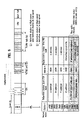
FIG. 5 shows a table for identifying an entry as the defect information in case of FIG. 4.
Referring to FIG. 5, if ‘status1=0000’, it means that the corresponding area is a normally replaced defective area (RAD entry). If ‘status1=1001’, it means that the corresponding area is decided as a defective area at high speed but as a non-defective area at low speed (NDR entry) and that recording speed information in case of deciding the non-defective area, i.e., information for low speed, is recorded within the corresponding NDR entry.
FIG. 6 and FIG. 7 are diagrams for recording to manage location information of a defective area according to a second embodiment of the present invention, in which location information for a defective area is recorded per cluster as a consecutive minimum recording unit.
Referring to FIG. 6, two types of defective areas exist within a data area. One defective area type corresponds to a case decided as a defective area at both high speed and low speed (A, B), whereas the other defective area type corresponds to a case decided as a defective area at high speed but as a non-defective area at low speed (C, D).
Hence, data to be recorded in the cluster-A and cluster-B are recorded by replacement in area-a and area-b within a spare area, respectively. For the information of a defective area for this, ‘status1=0000’ is recorded as RAD (re-allocatable-defect) type entry designating that information of the defective area is normally replaced, location information of the area-A and area-B is recorded in ‘Defective cluster first PSN’ field, and location information of the corresponding area-a and area-b is recorded in ‘Replacement cluster first PSN’ field to be managed.
Meanwhile, replacement recording is not performed on the area-C and area-D which are decided as defective areas at high speed only but as normal areas at low speed, whereby a defect information recording method of the area-C and area-D should be different from that of the area-A and area-B. And, it can be seen that the area-C corresponds to a case that a plurality of clusters are decided as a same area and that the area-D is an area corresponding to one cluster only. Hence, it is defined that ‘status1=1001’ is given to indicate the NDR (non-defective at low recording speed) type and that a binary value representing a number of consecutive recording units of the corresponding area is written in ‘status2’ field. For instance, 4-clusters are consecutive in the area-C, ‘status2=0100’ is recorded. The area-D consists of one cluster, ‘status2=0001’ is recorded. The rest fields are recorded like the first embodiment of the present invention. Location information of the area-C and area-D as start cluster of consecutive recording units is recorded in ‘Defective cluster first PSN’ field, and recording speed information of the case decided as a normal area is recorded in ‘Replacement cluster first PSN’ field since there exists no replaced area. When the corresponding optical disc is reloaded later to perform recording on the area-C and area-D, a recording/reproducing unit (‘10’ in FIG. 12) performs the recording by referring to the recording speed information recorded in the corresponding entry so that no defective area is generated from the consecutive clusters indicated by size information within defect management information. Thus, it is able to lower probability of defective area generation. Besides, it is also possible to record high speed information of the generated defective area as recording speed information recorded in ‘Replacement cluster first PSN’ field. As the system also enables to be informed by the high speed information that the defective area was generated at the speed written in the entry, it is able to perform recording at a predetermined speed lower than the written speed.
FIG. 7 shows a table for identifying an entry as the defect information in case of FIG. 6.
Referring to FIG. 5, if ‘status1=0000’, it means that the corresponding area is a normally replaced defective area (RAD entry). If ‘status1=1001’, it means that the corresponding area is decided as a defective area at high speed but as a non-defective area at low speed (NDR entry), that size information of consecutive clusters is recorded in ‘status2’ field within the NDR entry, and that recording speed information in case of deciding the non-defective area, i.e., information for low speed, is recorded in ‘Replacement cluster first PSN’ field within the corresponding NDR entry.
Compared to the first embodiment according to the present invention, the second embodiment according to the present invention is characterized in enabling to lower the number of entries.
FIG. 8 and FIG. 9 are diagrams for recording to manage location information of a defective area according to a third embodiment of the present invention, in which location information of an area decided as a defective area at high speed only but as a non-defective area at low speed is designated by a section to be recorded therein.
Referring to FIG. 8, two types of defective area sections exist within a data area. One defective area section type corresponds to a case decided as a defective area at both high speed and low speed (section A˜C, verify unit(k)), whereas the other defective area section type corresponds to a case decided as a defective area at high speed but as a non-defective area at low speed (section E˜F, verify unit(n)).
First of all, as a result of re-verifying the section A˜C, which was decided as a defective area at high speed, at low speed, the area-A, area-B, and area-C are decided as defective areas but the area-D is decided as a non-defective area at low speed. In such a case, defect information for the corresponding section is individually recorded per cluster in a defect management area.
Yet, as a result of re-verifying the section E˜F, which was decided as a defective area at high speed, at low speed, all clusters are decided as non-defective areas. In such a case, one defect information is recorded for the corresponding section overall (area-E to area-F).
Hence, data to be recorded in the cluster-A, cluster-B, and cluster-C are recorded by replacement in area-a, area-b, and area-C within a spare area, respectively. For the information of a defective area for this, ‘status1=0000’ is recorded as RAD (re-allocatable-defect) type entry designating that information of the defective area is normally replaced, location information of the area-A, area-B, and area-C is recorded in ‘Defective cluster first PSN’ field, and location information of the corresponding area-a, area-b, and area-c is recorded in ‘Replacement cluster first PSN’ field to be managed.
Meanwhile, replacement recording is not performed on the area-D, which is decided as a defective area at high speed only but as a normal area at low speed, within the section A˜C whereby a defect information recording method of the area-D should be different from that of the area-A, area-B, and area-C. Hence, ‘status1=1001’ is given to indicate the NDR (non-defective at low recording speed) type and ‘status2=0000’ is set to inform that the corresponding area is recorded as one cluster by one entry.
Yet, in order to represent this, the section E˜F needs a pair of entries (pair entry). In a first entry, ‘status2=0001’ informs a first one of a pair of entries and location informations of area-E and area-F meaning start and end clusters of the same section, respectively are recorded in ‘Defective cluster first PSN’ field and ‘Replacement cluster first PSN’ field, respectively. In a second entry, ‘status2=0010’ informs a second one of a pair of entries and recording speed information for low speed resulting in no defective area is repeatedly recorded in ‘Defective cluster first PSN’ field and ‘Replacement cluster first PSN’ field. Yet, the ‘Replacement cluster first PSN’ field of the second entry can be set to ‘00h’ instead of recording the recording speed information repeatedly.
Besides, it is also possible to record high speed information of the generated defective area as recording speed information recorded in ‘Defective cluster first PSN’ field of the second entry. As the system also enables to be informed by the high speed information that the defective area was generated from the corresponding section at the speed written in the entry, it is able to perform recording at a predetermined speed lower than the written speed.
FIG. 9 shows a table for identifying an entry as the defect information in case of FIG. 8.
Referring to FIG. 9, if ‘status1=0000’, it means that the corresponding area is a normally replaced defective area (RAD entry). If ‘status1=1001’, it means that the corresponding area is decided as a defective area at high speed but as a non-defective area at low speed (NDR entry). If ‘status2=0000’, it means one entry coping with each cluster. If ‘status2=0001’, it means the first entry of a pair of the entries indicating a specific section. If ‘status2=0010’, it means the second entry of a pair of the entries indicating the specific section.
The third embodiment of the present invention enables not only to cope with each section so that a system changes a recording speed per cluster but also to reduce a load.
FIG. 10 is a schematic structural diagram of a defect list applicable to the present invention.
Referring to FIG. 10, information for informing how many entries of a specific type exist among defect entries recorded in a corresponding DFL is included in a header of the DFL. Hence, by recording the numbers of RAD-entry and NDR-entry in header information, a system is facilitated to preferentially recognize the number of entries from the DFL header information.
FIG. 11 is another conceptional flowchart for explaining a defect management method coping with a recording speed according to the present invention, in which the conceptional flowchart of FIG. 3 is extended.
Referring to FIG. 11, a recording/reproducing apparatus (‘10’ in FIG. 12) having received a recording command initiates recording at maximum speed Vmax applicable by a disc and keeps performing the recording at Vmax unless a defective area is generated during the recording. If verifying the defective area, the recording/reproducing apparatus re-verifies existence or non-existence of a defect of the corresponding area at low speed Vnext lower than the maximum speed Vmax (Step 1).
If it is decided that the corresponding area is not a defective area in case of the recording at Vnext, location information of the corresponding area and recording speed information of non-existence of the defective area at Vnext are registered to DFL using one of the methods according to the first to third embodiments of the present invention in FIG. 4, FIG. 6, and FIG. 8. In doing so, as explained in the first to third embodiments of the present invention, ‘Vmax’ can be registered as the recording speed information to the DFL instead of Vnext. In the recording at Vnext, if the corresponding area is decided as the defective area like the recording at Vmax, existence or non-existence of a defect in the corresponding area is re-verified at Vnom corresponding to 1× speed applicable by the disc (Step 2).
In doing so, it is able to set up a plurality of recording speeds corresponding to the Vnext according to a system in Step 2. For instance, ‘Vmax=16× speed’, ‘Vnext1=8× speed’, ‘Vnext2=4× speed’, ‘Vnext3=2× speed’ are set up as the recording speeds, and Step 2 is repeated several times prior to verifying the corresponding area at a final recording speed of ‘Vnom=1× speed’.
Finally, if the corresponding area is decided as a non-defective area in case of the recording at Vnom, location information of the corresponding area and recording speed information of existence of the non-defective area at Vnom are registered to DFL using one of the methods according to the first to third embodiments of the present invention in FIG. 4, FIG. 6, and FIG. 8. In doing so, as explained in the first to third embodiments of the present invention, ‘Vnext’ can be registered as the recording speed information to the DFL instead of Vnom. In the recording at Vnom, if the corresponding area is decided as the non-defective area like the recording at Vnext, data of the corresponding area are transferred to a replacement area for replacement recording and location information of the defective area and the location information of the replacement area are registered to the DFL (Step 3).
FIG. 12 shows a recording/reproducing apparatus for an optical disc applicable to the present invention.
Referring to FIG. 12, a recording/reproducing apparatus according to the present invention includes a recorder/reproducer 10 carrying out recording/reproducing on an optical disc and a control unit 20 controlling the recorder/reproducer 10. The control unit 20 gives a recording or reproducing command for a specific area, and the recorder/reproducer 10 caries out the recording/reproducing on the specific area according to the command of the control unit 20. Specifically, the recorder/reproducer 10 includes an interface unit 12 performing communications with an external device, a pickup unit 11 directly recording data on the optical disc or reproducing the data, a data processor 13 receiving a reproducing signal from the pickup unit 11 to restore into a necessary signal value or modulating to deliver a signal to be recorded into a signal to be recorded on the optical disc, a servo unit 14 reading out a signal from the optical disc correctly or controlling the pickup unit 11 to record a signal on the optical disc correctly, a memory 15 temporarily storing various informations including a management information and data, and a microcomputer 16 responsible for controlling the above-described elements within the recorder/reproducer 10.
A recording process of an optical disc according to the present invention is explained in detail as follows.
First of all, once an optical disc is loaded in the recording/reproducing apparatus, the entire disc management information within the disc is read out to be temporarily stored in the memory 15 of the recorder/reproducer 10. And, various kinds of the disc management information are utilized for the recording/reproducing on/from the optical disc. Specifically, a defect list (DFL) recorded within a defect management area of the present invention is included in the management information stored in the memory 15. Hence, location information of a defective area and location information of a replacement area within the DFL are read out to be stored in the memory 15. In case of specific defect information (NDR-type), recording speed information is read out to be stored in the memory 15 as well. If the disc is a brand-new disc, such a defect information as NDR-type entry and RAD-type entry will not exist in the DFL within the defect management area.
If intending to perform a recording on a specific area within the optical disc, the control unit 20 renders such an intent into a writing command and then delivers it to the recorder/reproducer 10 together with data for writing location information of a recording-target area. After receiving the writing command, the microcomputer 16 decides the corresponding recording speed, which will be applied to the recording-target area within the optical disc by the control unit, from the defect management information stored in the memory 15. Specifically, if the recording-target area is registered as defect information (NDR type), the recording speed information recorded within the corresponding defect information is adopted to be decided as the recording speed for the corresponding area. If the recording-target area is not registered as defect information (NDR type), high speed applicable to the disc and system is decided as the recording speed.
Subsequently, it is verified whether a defective area is generated while the recording is performed at the decided high speed. If the defective area is generated at high speed as a result of the verification, the recording speed is changed into low speed and it is then re-verified whether a defective area is generated from the corresponding area. For an area decided as the defective area at both high and low speeds, data that will be written in the corresponding area are recorded in a replacement area by replacement. For an area decided as the defective area at high speed but as a non-defective area at low speed, the recording is performed at the low speed. And, the defective area generated from the recording is recorded in the defect management area in a manner of one of the embodiments according to the present invention shown in FIG. 4, FIG. 6, and FIG. 8. Yet, if an initially decided recording speed is low speed, the above-explained defective area management schemes are not adopted. Instead, the defect area management method of performing replacement recording on the entire defective areas is adopted to cope with the recording speeds.
Accordingly, the present invention proposes a defect management scheme coping with recording speeds in a high-speed recordable optical disc, thereby providing an accurate decision of the defective area to lower frequency of defective area generation. Specifically, the present invention provides optimal recording speed information for a specific section, thereby enabling to reduce a system load overall. Moreover, as optimal recording speed is applicable to re-recording in a specific section, thereby enabling to secure high reliance of data.
It will be apparent to those skilled in the art that various modifications and variations can be made in the present invention. Thus, it is intended that the present invention covers the modifications and variations of this invention provided they come within the scope of the appended claims and their equivalents.

Claims (18)

1. A method of managing a defective area in a recording medium, the method comprising:
(a) checking whether a defective area is generated at a first recording speed;
(b) if the defective area is generated at the first recording speed, checking whether the defective area is generated at a second recording speed, wherein the second recording speed is lower than the first recording speed; and
(c) determining whether to replace the defective area with a replacement area based on a result of the step (b),
wherein if the defective area is generated at the first recording speed and the defective area is not generated at the second recording speed, the method further comprises recording a management information to indicate at least a location of the defective area.
2. The method of claim 1, wherein the management information further includes status information indicating that the defective area is not replaced.
3. The method of claim 1, wherein the management information further includes speed information of the second recording speed.
4. The method of claim 1, wherein the management information further includes speed information of the first recording speed.
5. The method of claim 1, wherein the management information is recorded as one entry per minimum recording unit.
6. The method of claim 5, wherein the minimum recording unit is one cluster.
7. The method of claim 1, wherein the management information is recorded as one entry for a consecutive minimum recording unit.
8. The method of claim 7, wherein the entry includes information designating a number of the consecutive minimum recording unit.
9. The method of claim 1, wherein the management information includes a start position of the defective area and an end position of the defective area.
10. The method of claim 9, wherein the management information further includes speed information of first recording speed or second recording speed.
11. The method of claim 10, wherein the start position and the end position are included in a first entry and the speed information for the defective area is included in a second entry.
12. The method of claim 11, wherein identification information for identifying the first and second entries is recorded in the corresponding entry.
13. A method of managing a defective area of an optical recording medium, the method comprising:
verifying whether the defective area is generated in performing a recording at an applicable maximum speed;
re-verifying a presence or non-presence of a defect of a corresponding area by changing a recording speed into an intermediate speed lower than the applicable maximum speed at least one time if the defective area is generated at the applicable maximum speed;
re-verifying the presence or non-presence of the defect of the corresponding area by changing the recording speed into a minimum speed if the defective area is generated at the intermediate speed; and
recording a location information of an area decided as the defective area at a specific area of the optical recording medium according to a result of each of the first to third steps,
wherein for the area decided as the defective area at the first step but as a non-defective area at the second step, the location information of the corresponding area is recorded at the specific area.
14. The method of claim 13, wherein a recording speed information applied to the second step is further recorded at the specific area.
15. The method of claim 13, wherein a recording speed information applied to the first step is further recorded at the specific area.
16. A method for recording data on an optical recording medium, the method comprising:
receiving a recording command for a specific area;
verifying whether a defective area is generated on the specific area at a first speed;
re-verifying a presence or non-presence of a defect of a corresponding area by changing a recording speed into a second speed if the defective area is generated at the first speed, the second speed being lower than the first speed;
recording data to be recorded in a first area decided as the defective area at both of the first and second speeds in a replacement area as a result of re-verifying step; and
recording data at the second speed on a second area decided as the defective area at the first speed but as a non-defective area at the second speed,
wherein the step of recording the data at the second speed on the second area further includes recording a management information to indicate at least a location of the defective area.
17. An apparatus for managing a defective area in a recording medium, the apparatus comprising:
a control unit configured to:
first check whether a defective area is generated at a first recording speed;
second check whether the defective area is generated at a second recording speed; and
determine whether to replace the defective area with a replacement area based on the result of the second checking; and
a pickup unit configured to record or reproduce data on/from the recording medium according to controlling of the control unit,
wherein the second recording speed is lower than the first recording speed, and
wherein the control unit is further configured to control the pickup unit to record management information indicating at least a location of the defective area, if the defective area is generated at the first recording speed and the defective area is not generated at the second recording speed.
18. The apparatus of claim 17, further comprising:
a host configured to transmit a command for recording or reproducing data to or from a specific area of the recording medium to the control unit via an interface unit,
wherein the control unit is further configured to control the recording or reproducing according to the command from the host.
US10/891,029 2003-07-15 2004-07-15 Optical recording medium, method of managing defective area thereof, recording method thereof, and recording/reproducing apparatus thereof Expired - Fee Related US7539100B2 (en)

Applications Claiming Priority (2)

Application Number Priority Date Filing Date Title
KR1020030048330A KR101014703B1 (en) 2003-07-15 2003-07-15 Method and apparatus for managing a defective area on optical disc
KRP2003-48330 2003-07-15

Publications (2)

Publication Number Publication Date
US20050210319A1 US20050210319A1 (en) 2005-09-22
US7539100B2 true US7539100B2 (en) 2009-05-26

Family

ID=36923847

Family Applications (1)

Application Number Title Priority Date Filing Date
US10/891,029 Expired - Fee Related US7539100B2 (en) 2003-07-15 2004-07-15 Optical recording medium, method of managing defective area thereof, recording method thereof, and recording/reproducing apparatus thereof

Country Status (5)

Country Link
US (1) US7539100B2 (en)
KR (1) KR101014703B1 (en)
CN (1) CN1823372B (en)
TW (1) TWI304976B (en)
WO (1) WO2005006315A1 (en)

Cited By (3)

* Cited by examiner, † Cited by third party
Publication number Priority date Publication date Assignee Title
US20050259560A1 (en) * 2004-03-23 2005-11-24 Park Yong C Recording medium, and method and apparatus for recording and reproducing data on/from recording medium
US20060245332A1 (en) * 2005-04-29 2006-11-02 Mediatek Incorporation Method for controlling the record speed of a multi-layered optical disc
US8189439B2 (en) * 2010-07-16 2012-05-29 Mediatek Inc. Data recording method and apparatus for re-verifying correctness of recorded data on optical storage medium

Families Citing this family (14)

* Cited by examiner, † Cited by third party
Publication number Priority date Publication date Assignee Title
US7233550B2 (en) 2002-09-30 2007-06-19 Lg Electronics Inc. Write-once optical disc, and method and apparatus for recording management information on write-once optical disc
KR20040028469A (en) 2002-09-30 2004-04-03 엘지전자 주식회사 Method for managing a defect area on optical disc write once
KR101036473B1 (en) 2002-12-11 2011-05-24 엘지전자 주식회사 Method of managing overwrite and method of recording management inforamtion on an optical disc write once
TWI314315B (en) 2003-01-27 2009-09-01 Lg Electronics Inc Optical disc of write once type, method, and apparatus for managing defect information on the optical disc
US7663997B2 (en) 2003-05-09 2010-02-16 Lg Electronics, Inc. Write once optical disc, and method and apparatus for recovering disc management information from the write once optical disc
US7313065B2 (en) 2003-08-05 2007-12-25 Lg Electronics Inc. Write-once optical disc, and method and apparatus for recording/reproducing management information on/from optical disc
JP4713140B2 (en) * 2004-12-13 2011-06-29 株式会社日立製作所 Digital data recording method, recording apparatus and reproducing apparatus
JP2007080351A (en) * 2005-09-13 2007-03-29 Funai Electric Co Ltd Optical disk recording and reproducing apparatus
JP4335859B2 (en) * 2005-09-15 2009-09-30 株式会社日立エルジーデータストレージ Information recording / reproducing apparatus and information reproducing apparatus
KR101227485B1 (en) 2005-11-25 2013-01-29 엘지전자 주식회사 Recording mdium, Method and Apparatus for recording defect management information on the recording medium
ES2394649T3 (en) 2006-03-20 2013-02-04 Beele Engineering B.V. System to dynamically seal a conduit sleeve through which a tube or cable extends
JP2008287781A (en) * 2007-05-16 2008-11-27 Teac Corp Optical disk device
JP5157965B2 (en) * 2009-03-02 2013-03-06 株式会社日立製作所 Optical information recording / reproducing apparatus, optical information reproducing apparatus, and optical information recording medium
KR101042153B1 (en) * 2009-06-25 2011-06-16 도시바삼성스토리지테크놀러지코리아 주식회사 Method for determining data writing speed

Citations (95)

* Cited by examiner, † Cited by third party
Publication number Priority date Publication date Assignee Title
US4733386A (en) 1985-05-02 1988-03-22 Hitachi, Ltd. Method of writing file data into a write-once type memory device
US4807205A (en) 1985-11-29 1989-02-21 Michel Picard Process for writing with updating and reading informations on a non-erasable support organized into sectors
US5068842A (en) 1987-11-13 1991-11-26 Pioneer Electronic Corporation Control method of disk drive for recordable optical disk
US5111444A (en) 1988-07-13 1992-05-05 Matsushita Electric Industrial Co., Ltd. Method of managing defective sectors in a disk-shaped information recording medium and an apparatus for performing the same
US5210734A (en) 1989-08-30 1993-05-11 Victor Company Of Japan, Ltd. Information management method for appendage type additional information recording medium
US5235585A (en) 1991-09-11 1993-08-10 International Business Machines Reassigning defective sectors on a disk
US5237553A (en) 1990-05-24 1993-08-17 Matsushita Electric Industrial Co. Data recording and reproducing apparatus having a plurality of operating modes
US5247494A (en) 1984-06-08 1993-09-21 Matsushita Electric Industrial Co. Ltd. Method for recording and reproducing information on and from an optical disk having a read-only recorded zone and a writable and readable zone using a spot laser light
US5319626A (en) 1990-08-27 1994-06-07 Mitsubishi Electric Corporation Method for rewriting defect management areas on optical disk according to ECMA standard
US5404357A (en) 1991-06-27 1995-04-04 Matsushita Electric Industrial Co., Ltd. Information writing and reading apparatus
US5442611A (en) 1992-05-07 1995-08-15 Olympus Optical Co., Ltd. Method of recording information on record medium having data record region and file management information record region
US5448728A (en) 1991-08-08 1995-09-05 Sharp Kabushiki Kaisha Storage medium control system for controlling a write-once read-many storage medium
US5475820A (en) 1990-09-17 1995-12-12 Hewlett-Packard Company Method for using one of two storage directories only after the other directory is full for write management in a disk device
US5481519A (en) 1990-10-03 1996-01-02 Canon Kabushiki Kaisha Method for recording, reproducing and managing file data on a recording medium
US5495466A (en) 1994-01-10 1996-02-27 Eastman Kodak Company Write verification in an optical recording system by sensing mark formation while writing
US5528571A (en) 1993-06-08 1996-06-18 Sony Corporation Optical disc apparatus
US5553045A (en) 1992-07-31 1996-09-03 Sony Corporation Disk recording method and apparatus for indentifying and skipping defective clusters
US5577194A (en) 1992-10-30 1996-11-19 Intel Corporation Method of managing defects in flash disk memories
US5608715A (en) 1994-07-26 1997-03-04 Pioneer Electronic Corporation Multi-layered recording disk and recording/reproducing system using the same
US5715221A (en) 1995-04-21 1998-02-03 Matsushita Electric Industrial Method for managing defects in an information recording medium, and a device and information recording medium using said method
US5720030A (en) 1994-08-22 1998-02-17 Seiko Epson Corporation Preprocess method, information read/write method, input/output device and read/write device
US5740435A (en) 1994-10-31 1998-04-14 Sony Corporation Data management apparatus and method for managing data of variable lengths recorded on a record medium
US5745444A (en) 1994-12-19 1998-04-28 Hitachi, Ltd. Method of controlling recording information on an optical disk using replacement control information
US5799212A (en) 1993-02-26 1998-08-25 Sony Corporation Efficient recording medium
US5802028A (en) 1994-11-18 1998-09-01 Sony Corporation Method of data management using recorded flags to discriminate used allocation blocks and unwritten allocation blocks
US5805536A (en) 1996-11-07 1998-09-08 Eastman Kodak Company Method for bandwidth reduction in writeable optical data storage apparatus
US5867455A (en) 1993-12-07 1999-02-02 Hitachi, Ltd. Optical method and device for irradiating domains at predetermined positions
US5914928A (en) 1996-03-25 1999-06-22 Kabushiki Kaisha Toshiba Information recording disk having replacement area
US5940702A (en) 1994-11-29 1999-08-17 Nec Corporation Method for forming a cylindrical stacked capacitor in a semiconductor device
US6118608A (en) * 1997-03-12 2000-09-12 International Business Machines Corporation Disk drive unit and error recovery method executing shorter error recovery procedure when write errors and reset instruction occur
US6138203A (en) 1995-11-10 2000-10-24 Sony Corporation Information processing apparatus and method enabling a write-once recording medium to be utilized as a rewriteable recording medium
US6160778A (en) 1999-03-08 2000-12-12 Matsushita Electric Industrial Co., Ltd. Information recording medium, information recording method, information recording apparatus and information reproducing apparatus
US6189118B1 (en) 1998-10-22 2001-02-13 Matsushita Electric Industrial Co., Ltd. Information recording medium, and method and apparatus for managing defect thereof
US6233654B1 (en) 1996-03-05 2001-05-15 Sony Corporation Recording apparatus having a partially exchangeable disk array, a loading/unloading device, and a control device and which uses a disk-like recording medium
US20010009537A1 (en) 2000-01-26 2001-07-26 Lg Electronics, Inc. Method of formatting optical recording medium
US20010011267A1 (en) 1999-03-03 2001-08-02 Sony Corporation Nonvolatile memory and nonvolatile memory reproducing apparatus
US20010026511A1 (en) 2000-03-08 2001-10-04 Hiroshi Ueda Information recording medium, information recording method and information reproduction method
US6341109B1 (en) 1999-02-05 2002-01-22 Nec Corporation Defective area replacement method and information writing/reading device
US20020025138A1 (en) 2000-01-11 2002-02-28 Hitachi, Ltd. Apparatus and method for recording and reproducing information
US6373800B1 (en) 1998-09-14 2002-04-16 Kabushiki Kaisha Toshiba Information recording apparatus and method with replacement process
US6405332B1 (en) 1998-05-27 2002-06-11 Oki Electric Industry Co, Ltd. Storage device and alternate processing method for defective sectors of the same
US6414923B1 (en) 1998-08-17 2002-07-02 Lg Electronics Inc. Recording/reproducing method of optical recording medium
US20020097665A1 (en) 1998-10-10 2002-07-25 Samsung Electronics Co., Ltd. Recording medium having spare areas for defect management and method of allocating spare areas
US6447126B1 (en) 1994-11-02 2002-09-10 Texas Instruments Incorporated Support post architecture for micromechanical devices
US6466532B1 (en) 1998-11-10 2002-10-15 Samsung Electronics Co., Ltd. Recording medium having spare area for defect management and information on defect management, and method and apparatus of allocating spare area and managing defects
US6469978B1 (en) 1997-12-18 2002-10-22 Mitsubishi Denki Kabushiki Kaisha Rewritable optical disk with spare area and optical disk processing apparatus
US6477126B1 (en) 1998-11-20 2002-11-05 Lg Electronics Inc. Optical recording medium and method of assigning its spare area
US6480446B1 (en) 1998-04-20 2002-11-12 Samsung Electronics Co., Ltd. Recording medium for storing defect management information for recording real time data, defect managing method therefor and real time data recording method
US6493301B1 (en) 1999-01-13 2002-12-10 Lg Electronics Inc. Optical recording medium and method of managing defect area of the optical recording medium
US6496807B1 (en) 1998-09-22 2002-12-17 Sony Corporation Recording medium, recording method and recording apparatus incorporating anti-tamper features involving writing billing information into a write-once area
US6529458B1 (en) 1998-09-26 2003-03-04 Lg Electronics Inc. Method for managing defective area of optical recording medium
US6542450B1 (en) 1998-11-11 2003-04-01 Lg Electronics Inc. Method for assigning spare area in optical recording medium
US6564345B1 (en) 1998-03-02 2003-05-13 Lg Electronics, Inc. Method for creating defect management information in an recording medium, and apparatus and medium based on said method
US20030095482A1 (en) * 2001-11-20 2003-05-22 Chien-Li Hung Method for adjusting the writing speed of a CD drive
US6581167B1 (en) 1999-02-01 2003-06-17 Matsushita Electric Industrial Co., Ltd. Information recording medium, information recording method and information recording/reproduction system
US6606285B1 (en) 1999-09-23 2003-08-12 Koninklijke Philips Electronics N.V. Method of immediate writing or reading files on a disc like recording medium
US6615363B1 (en) 1999-03-19 2003-09-02 Hitachi Maxell, Ltd. Optical disk and method of recording on the same
US6631106B1 (en) 1998-07-21 2003-10-07 Fujitsu Limited Spare area with a predetermined capacity for a detective sector allocated in each zone
US6633724B1 (en) 1998-02-25 2003-10-14 Hitachi, Ltd. Realtime data recording method
US20030198155A1 (en) * 2002-04-17 2003-10-23 Samsung Electronics Co., Ltd Apparatus and method for changing speed of recording on optical recording medium during recording operation
US6667939B1 (en) 2000-09-18 2003-12-23 Hitachi, Ltd. Optical disk and optical recording apparatus for said disk
US6671249B2 (en) 1999-12-28 2003-12-30 Mitsubishi Chemical Corporation Optical recording medium, data recording method for rewritable-type phase change type optical disc, data erase method for rewritable compact disc, data erase method for rewritable phase change type recording medium, read only data erase method, and recording/readout apparatus
US6697306B2 (en) 2000-07-31 2004-02-24 Sony Corporation Data recording method, data outputting method, and data recording and/or reproducing method
US6714502B2 (en) 2000-04-08 2004-03-30 Samsung Electronics Co., Ltd Method of verifying defect management area information of optical disc and apparatus for performing the same
US6724701B2 (en) 2000-06-06 2004-04-20 Koninklijke Philips Electronics N.V. Method of immediate writing or reading files on a disc like recording medium
US6763429B1 (en) 2000-03-31 2004-07-13 Hitachi, Ltd. Method and apparatus for recording and playing back information
US6766418B1 (en) 2001-04-30 2004-07-20 Emc Corporation Methods and apparatus for accessing data using a cache
US6785206B1 (en) 1999-05-08 2004-08-31 Samsung Electronics Co., Ltd. Recording medium for storing linking type information and method of processing defective area using the same
US6788631B1 (en) 1998-09-02 2004-09-07 Lc Electronics Inc. Optical recording medium having recording capacity information and method for indicating recording capacity
US6795389B1 (en) 1998-09-10 2004-09-21 Matsushita Electric Industrial Co., Ltd. Optical information recording medium with substrate and multiple information
US6804797B2 (en) 2000-04-08 2004-10-12 Samsung Electronics, Co., Ltd. Method of verifying defect management area information of disc and test apparatus for performing the same
US6826140B2 (en) 2002-08-26 2004-11-30 Bae Systems Information And Electronic Systems Integration Inc Multichannel digital recording system with multi-user detection
US6842580B1 (en) 1999-01-27 2005-01-11 Matsushita Electric Industrial Co., Ltd. Real-time recording/reproduction on an information recording medium including a defective region
US6845069B2 (en) 2000-07-26 2005-01-18 Pioneer Corporation Information editing apparatus, information editing method, and information recording medium on which program for controlling edit is recorded so as to be read by computer
US6883111B2 (en) 2001-11-12 2005-04-19 Hitachi, Ltd. Data recording method and data recording apparatus
US6918003B2 (en) 2002-01-15 2005-07-12 Ricoh Company, Ltd. Information reproducing apparatus, data management information obtaining method, data management information obtaining program, and storage medium
US6934236B2 (en) 2002-08-03 2005-08-23 Samsung Electronics Co., Ltd. Information storage medium having updatable control information and recording and/or reproducing method thereof
US6999398B2 (en) 2001-03-30 2006-02-14 Canon Kabushiki Kaisha Method and apparatus for recording information on information recording medium
US7002882B2 (en) 2001-03-22 2006-02-21 Kabushiki Kaisha Toshiba Information recording medium capable of defect management, information recording apparatus capable of defect management, and information playback apparatus for playing back information from defect-managed medium
US7027059B2 (en) 2002-05-30 2006-04-11 Intel Corporation Dynamically constructed rasterizers
US7042825B2 (en) 2002-01-31 2006-05-09 Matsushita Electric Industrial Co., Ltd. Information recording medium, recording apparatus, reproduction apparatus, recording method, reproduction method and defect management method
US7050701B1 (en) 1998-09-25 2006-05-23 Matsushita Electric Industrial Co., Ltd. Information recording medium, information recording/reproducing method, and information recording/reproducing device
US7092334B2 (en) * 2001-04-12 2006-08-15 Hitachi-Lg Data Storage Korea, Inc. Method of detecting a defect area of a disk
US7123556B2 (en) 2002-01-22 2006-10-17 Matsushita Electric Industrial Co., Ltd. Multi-layered information recording medium with spare defect management areas
US7149930B2 (en) 2002-06-25 2006-12-12 Hitachi Global Storage Technologies Japan, Ltd. Recording/reproducing apparatus
US7184377B2 (en) 2002-01-22 2007-02-27 Matsushita Electric Industrial Co., Ltd. Multi-layered information recording medium, recording apparatus, and recording method
US7188271B2 (en) 2003-02-25 2007-03-06 Lg Electronics Inc. Write-once optical disc, and method and apparatus for recording management information on write-once optical disc
US7233550B2 (en) 2002-09-30 2007-06-19 Lg Electronics Inc. Write-once optical disc, and method and apparatus for recording management information on write-once optical disc
US7272086B2 (en) 2003-03-24 2007-09-18 Samsung Electronics Co., Ltd. Method of overwriting data in write-once information storage medium and data recording and/or reproducing apparatus for write-once information storage medium
US7289404B2 (en) 2003-03-13 2007-10-30 Lg Electronics Inc. Write-once recording medium and defective area management method and apparatus for write-once recording medium
US7296178B2 (en) 2003-03-17 2007-11-13 Pioneer Corporation Write-once-type recording medium, recording apparatus and method for write-once-type recording medium, and reproducing apparatus and method for write-once-type recording medium
US7313066B2 (en) 2003-03-13 2007-12-25 Samsung Electronics Co., Ltd. Write once disc allowing management of data area, method of managing the data area, and method for reproducing data from write once disc
US7327654B2 (en) 2002-10-18 2008-02-05 Samsung Electronics Co., Ltd. Method of and apparatus for managing disc defects using temporary defect management information (TDFL) and temporary defect management information (TDDS), and disc having the TDFL and TDDS
US7349301B2 (en) 2002-11-22 2008-03-25 Sony Corporation Write-once recording medium on which portion of the data is logically overwritten
US7379402B2 (en) 2002-08-12 2008-05-27 Samsung Electronics Co., Ltd. Disc with temporary disc definition structure (TDDS) and temporary defect list (TDFL), and method of and apparatus for managing defect in the same

Family Cites Families (27)

* Cited by examiner, † Cited by third party
Publication number Priority date Publication date Assignee Title
KR100239118B1 (en) * 1997-05-21 2000-01-15 구자홍 Optical disk having variable margin region rate and variably setting method of margin region rate on disk
CN1162858C (en) * 1999-10-22 2004-08-18 明碁电脑股份有限公司 Method for planning particular cell in more memory cells
AU2001275040A1 (en) * 2000-05-30 2001-12-11 Dataplay, Inc. Defect management system for write-once storage disk
US20020099950A1 (en) * 2001-01-22 2002-07-25 Smith Kenneth K. Method of maintaining integrity of an instruction or data set
JP2002334527A (en) * 2001-05-11 2002-11-22 Matsushita Electric Ind Co Ltd Disk memory device, defect determination method for disk memory device, and recording medium
JP3925144B2 (en) * 2001-10-12 2007-06-06 株式会社日立製作所 Recording method and recording medium
CN1615515A (en) * 2002-01-18 2005-05-11 皇家飞利浦电子股份有限公司 Optical data storage medium and use of such medium
JP2004014088A (en) * 2002-06-11 2004-01-15 Sony Corp Disk recording medium, recording method and disk drive system
TWI248067B (en) * 2002-07-04 2006-01-21 Mediatek Inc Method for managing spare blocks of optical disk
KR100888591B1 (en) * 2002-09-10 2009-03-16 삼성전자주식회사 Method and apparatus for allotting adaptively spare area and disc thereof
BRPI0306564B1 (en) * 2002-09-26 2016-04-26 Lg Electronics Inc method of recording optical media management having at least one defective area in the user data area, recording media and recording optical media management apparatus having at least one temporary defect management area and a spare area in the data area
KR20040028469A (en) * 2002-09-30 2004-04-03 엘지전자 주식회사 Method for managing a defect area on optical disc write once
KR100739673B1 (en) * 2002-10-10 2007-07-13 삼성전자주식회사 Method for managing defect using temporary DFL and temporary DDS
EP1579443A1 (en) * 2002-12-11 2005-09-28 LG Electronics Inc. Method and apparatus for managing overwrite on an optical disc write once
KR101036473B1 (en) * 2002-12-11 2011-05-24 엘지전자 주식회사 Method of managing overwrite and method of recording management inforamtion on an optical disc write once
US7372788B2 (en) * 2003-01-14 2008-05-13 Lg Electronics Inc. Method for managing defective area on write-once optical recording medium, and optical recording medium using the same
US7672204B2 (en) * 2003-01-27 2010-03-02 Lg Electronics Inc. Optical disc, method and apparatus for managing a defective area on an optical disc
TWI314315B (en) * 2003-01-27 2009-09-01 Lg Electronics Inc Optical disc of write once type, method, and apparatus for managing defect information on the optical disc
JP4110000B2 (en) * 2003-01-28 2008-07-02 株式会社ルネサステクノロジ Storage device
KR100923652B1 (en) * 2003-07-08 2009-10-28 파나소닉 주식회사 A write-once recording medium, a reproducing method, and a recording method
WO2005006314A1 (en) * 2003-07-14 2005-01-20 Lg Electronics Inc. Write-once optical disc, method and apparatus for recording management information on write-once optical disc
KR20050009031A (en) * 2003-07-15 2005-01-24 엘지전자 주식회사 Method for recording management information on optical disc write once
US7313065B2 (en) * 2003-08-05 2007-12-25 Lg Electronics Inc. Write-once optical disc, and method and apparatus for recording/reproducing management information on/from optical disc
JP4145749B2 (en) * 2003-08-12 2008-09-03 パイオニア株式会社 Information recording medium, recording apparatus and recording method for information recording medium, reproducing apparatus and reproducing method for information recording medium, computer program for recording or reproduction control, and data structure including control signal
WO2005024793A2 (en) * 2003-09-08 2005-03-17 Lg Electronics Inc. Write-once optical disc, and method and apparatus for recording management information thereon
BRPI0414208A (en) * 2003-09-08 2006-10-31 Lg Electronics Inc method and apparatus for recording management information, physical recording medium
WO2005024791A2 (en) * 2003-09-08 2005-03-17 Lg Electronics Inc. Write-once optical disc and method for recording management information thereon

Patent Citations (104)

* Cited by examiner, † Cited by third party
Publication number Priority date Publication date Assignee Title
US5247494A (en) 1984-06-08 1993-09-21 Matsushita Electric Industrial Co. Ltd. Method for recording and reproducing information on and from an optical disk having a read-only recorded zone and a writable and readable zone using a spot laser light
US4733386A (en) 1985-05-02 1988-03-22 Hitachi, Ltd. Method of writing file data into a write-once type memory device
US4807205A (en) 1985-11-29 1989-02-21 Michel Picard Process for writing with updating and reading informations on a non-erasable support organized into sectors
US5068842A (en) 1987-11-13 1991-11-26 Pioneer Electronic Corporation Control method of disk drive for recordable optical disk
US5111444A (en) 1988-07-13 1992-05-05 Matsushita Electric Industrial Co., Ltd. Method of managing defective sectors in a disk-shaped information recording medium and an apparatus for performing the same
US5210734A (en) 1989-08-30 1993-05-11 Victor Company Of Japan, Ltd. Information management method for appendage type additional information recording medium
US5237553A (en) 1990-05-24 1993-08-17 Matsushita Electric Industrial Co. Data recording and reproducing apparatus having a plurality of operating modes
US5319626A (en) 1990-08-27 1994-06-07 Mitsubishi Electric Corporation Method for rewriting defect management areas on optical disk according to ECMA standard
US5475820A (en) 1990-09-17 1995-12-12 Hewlett-Packard Company Method for using one of two storage directories only after the other directory is full for write management in a disk device
US5481519A (en) 1990-10-03 1996-01-02 Canon Kabushiki Kaisha Method for recording, reproducing and managing file data on a recording medium
US5404357A (en) 1991-06-27 1995-04-04 Matsushita Electric Industrial Co., Ltd. Information writing and reading apparatus
US5448728A (en) 1991-08-08 1995-09-05 Sharp Kabushiki Kaisha Storage medium control system for controlling a write-once read-many storage medium
US5235585A (en) 1991-09-11 1993-08-10 International Business Machines Reassigning defective sectors on a disk
US5442611A (en) 1992-05-07 1995-08-15 Olympus Optical Co., Ltd. Method of recording information on record medium having data record region and file management information record region
US5553045A (en) 1992-07-31 1996-09-03 Sony Corporation Disk recording method and apparatus for indentifying and skipping defective clusters
US6058085A (en) 1992-07-31 2000-05-02 Sony Corporation Method and apparatus for identifying and skipping defective sections
US5577194A (en) 1992-10-30 1996-11-19 Intel Corporation Method of managing defects in flash disk memories
US5799212A (en) 1993-02-26 1998-08-25 Sony Corporation Efficient recording medium
US5528571A (en) 1993-06-08 1996-06-18 Sony Corporation Optical disc apparatus
US5867455A (en) 1993-12-07 1999-02-02 Hitachi, Ltd. Optical method and device for irradiating domains at predetermined positions
US5495466A (en) 1994-01-10 1996-02-27 Eastman Kodak Company Write verification in an optical recording system by sensing mark formation while writing
US5608715A (en) 1994-07-26 1997-03-04 Pioneer Electronic Corporation Multi-layered recording disk and recording/reproducing system using the same
US5720030A (en) 1994-08-22 1998-02-17 Seiko Epson Corporation Preprocess method, information read/write method, input/output device and read/write device
US5740435A (en) 1994-10-31 1998-04-14 Sony Corporation Data management apparatus and method for managing data of variable lengths recorded on a record medium
US6341278B1 (en) 1994-10-31 2002-01-22 Sony Corporation Recording and reproducing apparatus and method for accessing data stored on a randomly accessible recording medium, and for managing data thereon
US6447126B1 (en) 1994-11-02 2002-09-10 Texas Instruments Incorporated Support post architecture for micromechanical devices
US5848038A (en) 1994-11-18 1998-12-08 Sony Corporation Method of data management using recorded flags to discriminate used allocation blocks and unwritten allocation blocks
US5802028A (en) 1994-11-18 1998-09-01 Sony Corporation Method of data management using recorded flags to discriminate used allocation blocks and unwritten allocation blocks
US5940702A (en) 1994-11-29 1999-08-17 Nec Corporation Method for forming a cylindrical stacked capacitor in a semiconductor device
US5745444A (en) 1994-12-19 1998-04-28 Hitachi, Ltd. Method of controlling recording information on an optical disk using replacement control information
US5715221A (en) 1995-04-21 1998-02-03 Matsushita Electric Industrial Method for managing defects in an information recording medium, and a device and information recording medium using said method
US6138203A (en) 1995-11-10 2000-10-24 Sony Corporation Information processing apparatus and method enabling a write-once recording medium to be utilized as a rewriteable recording medium
US6233654B1 (en) 1996-03-05 2001-05-15 Sony Corporation Recording apparatus having a partially exchangeable disk array, a loading/unloading device, and a control device and which uses a disk-like recording medium
US5914928A (en) 1996-03-25 1999-06-22 Kabushiki Kaisha Toshiba Information recording disk having replacement area
US5805536A (en) 1996-11-07 1998-09-08 Eastman Kodak Company Method for bandwidth reduction in writeable optical data storage apparatus
US6118608A (en) * 1997-03-12 2000-09-12 International Business Machines Corporation Disk drive unit and error recovery method executing shorter error recovery procedure when write errors and reset instruction occur
US6469978B1 (en) 1997-12-18 2002-10-22 Mitsubishi Denki Kabushiki Kaisha Rewritable optical disk with spare area and optical disk processing apparatus
US6738341B2 (en) 1997-12-18 2004-05-18 Mitsubishi Denki Kabushiki Kaisha Rewritable optical disk with spare area and optical disk processing apparatus
US6633724B1 (en) 1998-02-25 2003-10-14 Hitachi, Ltd. Realtime data recording method
US6754860B2 (en) 1998-03-02 2004-06-22 Lg Electronics, Inc. Method for creating defect management information in an recording medium, and apparatus and medium based on said method
US6564345B1 (en) 1998-03-02 2003-05-13 Lg Electronics, Inc. Method for creating defect management information in an recording medium, and apparatus and medium based on said method
US6480446B1 (en) 1998-04-20 2002-11-12 Samsung Electronics Co., Ltd. Recording medium for storing defect management information for recording real time data, defect managing method therefor and real time data recording method
US6405332B1 (en) 1998-05-27 2002-06-11 Oki Electric Industry Co, Ltd. Storage device and alternate processing method for defective sectors of the same
US6631106B1 (en) 1998-07-21 2003-10-07 Fujitsu Limited Spare area with a predetermined capacity for a detective sector allocated in each zone
US6414923B1 (en) 1998-08-17 2002-07-02 Lg Electronics Inc. Recording/reproducing method of optical recording medium
US6788631B1 (en) 1998-09-02 2004-09-07 Lc Electronics Inc. Optical recording medium having recording capacity information and method for indicating recording capacity
US6795389B1 (en) 1998-09-10 2004-09-21 Matsushita Electric Industrial Co., Ltd. Optical information recording medium with substrate and multiple information
US6373800B1 (en) 1998-09-14 2002-04-16 Kabushiki Kaisha Toshiba Information recording apparatus and method with replacement process
US6496807B1 (en) 1998-09-22 2002-12-17 Sony Corporation Recording medium, recording method and recording apparatus incorporating anti-tamper features involving writing billing information into a write-once area
US7050701B1 (en) 1998-09-25 2006-05-23 Matsushita Electric Industrial Co., Ltd. Information recording medium, information recording/reproducing method, and information recording/reproducing device
US6529458B1 (en) 1998-09-26 2003-03-04 Lg Electronics Inc. Method for managing defective area of optical recording medium
US20020097665A1 (en) 1998-10-10 2002-07-25 Samsung Electronics Co., Ltd. Recording medium having spare areas for defect management and method of allocating spare areas
US6189118B1 (en) 1998-10-22 2001-02-13 Matsushita Electric Industrial Co., Ltd. Information recording medium, and method and apparatus for managing defect thereof
US6466532B1 (en) 1998-11-10 2002-10-15 Samsung Electronics Co., Ltd. Recording medium having spare area for defect management and information on defect management, and method and apparatus of allocating spare area and managing defects
US6542450B1 (en) 1998-11-11 2003-04-01 Lg Electronics Inc. Method for assigning spare area in optical recording medium
US6477126B1 (en) 1998-11-20 2002-11-05 Lg Electronics Inc. Optical recording medium and method of assigning its spare area
US6493301B1 (en) 1999-01-13 2002-12-10 Lg Electronics Inc. Optical recording medium and method of managing defect area of the optical recording medium
US6842580B1 (en) 1999-01-27 2005-01-11 Matsushita Electric Industrial Co., Ltd. Real-time recording/reproduction on an information recording medium including a defective region
US6581167B1 (en) 1999-02-01 2003-06-17 Matsushita Electric Industrial Co., Ltd. Information recording medium, information recording method and information recording/reproduction system
US6341109B1 (en) 1999-02-05 2002-01-22 Nec Corporation Defective area replacement method and information writing/reading device
US20010011267A1 (en) 1999-03-03 2001-08-02 Sony Corporation Nonvolatile memory and nonvolatile memory reproducing apparatus
US6292445B1 (en) 1999-03-08 2001-09-18 Matsushita Electric Industrial Co., Ltd. Information recording medium, information recording method, information recording apparatus and information reproducing apparatus
US6160778A (en) 1999-03-08 2000-12-12 Matsushita Electric Industrial Co., Ltd. Information recording medium, information recording method, information recording apparatus and information reproducing apparatus
US20010043525A1 (en) * 1999-03-08 2001-11-22 Matsushita Electric Industrial Co., Ltd. Information recording medium, information recording method, information recording apparatus and information reproducing apparatus
US6615363B1 (en) 1999-03-19 2003-09-02 Hitachi Maxell, Ltd. Optical disk and method of recording on the same
US6785206B1 (en) 1999-05-08 2004-08-31 Samsung Electronics Co., Ltd. Recording medium for storing linking type information and method of processing defective area using the same
US6606285B1 (en) 1999-09-23 2003-08-12 Koninklijke Philips Electronics N.V. Method of immediate writing or reading files on a disc like recording medium
US6760288B2 (en) 1999-09-23 2004-07-06 Koninklijke Philips Electronics N.V. Method of immediate writing or reading files on a disc like recording medium
US6671249B2 (en) 1999-12-28 2003-12-30 Mitsubishi Chemical Corporation Optical recording medium, data recording method for rewritable-type phase change type optical disc, data erase method for rewritable compact disc, data erase method for rewritable phase change type recording medium, read only data erase method, and recording/readout apparatus
US20020025138A1 (en) 2000-01-11 2002-02-28 Hitachi, Ltd. Apparatus and method for recording and reproducing information
US20010009537A1 (en) 2000-01-26 2001-07-26 Lg Electronics, Inc. Method of formatting optical recording medium
US7027373B2 (en) 2000-03-08 2006-04-11 Matsushita Electric Industrial Co., Ltd. Information recording medium, information recording method and information reproduction method
US20010026511A1 (en) 2000-03-08 2001-10-04 Hiroshi Ueda Information recording medium, information recording method and information reproduction method
US6763429B1 (en) 2000-03-31 2004-07-13 Hitachi, Ltd. Method and apparatus for recording and playing back information
US6714502B2 (en) 2000-04-08 2004-03-30 Samsung Electronics Co., Ltd Method of verifying defect management area information of optical disc and apparatus for performing the same
US6804797B2 (en) 2000-04-08 2004-10-12 Samsung Electronics, Co., Ltd. Method of verifying defect management area information of disc and test apparatus for performing the same
US6724701B2 (en) 2000-06-06 2004-04-20 Koninklijke Philips Electronics N.V. Method of immediate writing or reading files on a disc like recording medium
US6845069B2 (en) 2000-07-26 2005-01-18 Pioneer Corporation Information editing apparatus, information editing method, and information recording medium on which program for controlling edit is recorded so as to be read by computer
US6697306B2 (en) 2000-07-31 2004-02-24 Sony Corporation Data recording method, data outputting method, and data recording and/or reproducing method
US6667939B1 (en) 2000-09-18 2003-12-23 Hitachi, Ltd. Optical disk and optical recording apparatus for said disk
US7002882B2 (en) 2001-03-22 2006-02-21 Kabushiki Kaisha Toshiba Information recording medium capable of defect management, information recording apparatus capable of defect management, and information playback apparatus for playing back information from defect-managed medium
US6999398B2 (en) 2001-03-30 2006-02-14 Canon Kabushiki Kaisha Method and apparatus for recording information on information recording medium
US7092334B2 (en) * 2001-04-12 2006-08-15 Hitachi-Lg Data Storage Korea, Inc. Method of detecting a defect area of a disk
US6766418B1 (en) 2001-04-30 2004-07-20 Emc Corporation Methods and apparatus for accessing data using a cache
US6883111B2 (en) 2001-11-12 2005-04-19 Hitachi, Ltd. Data recording method and data recording apparatus
US20030095482A1 (en) * 2001-11-20 2003-05-22 Chien-Li Hung Method for adjusting the writing speed of a CD drive
US6918003B2 (en) 2002-01-15 2005-07-12 Ricoh Company, Ltd. Information reproducing apparatus, data management information obtaining method, data management information obtaining program, and storage medium
US7184377B2 (en) 2002-01-22 2007-02-27 Matsushita Electric Industrial Co., Ltd. Multi-layered information recording medium, recording apparatus, and recording method
US7123556B2 (en) 2002-01-22 2006-10-17 Matsushita Electric Industrial Co., Ltd. Multi-layered information recording medium with spare defect management areas
US7042825B2 (en) 2002-01-31 2006-05-09 Matsushita Electric Industrial Co., Ltd. Information recording medium, recording apparatus, reproduction apparatus, recording method, reproduction method and defect management method
US20030198155A1 (en) * 2002-04-17 2003-10-23 Samsung Electronics Co., Ltd Apparatus and method for changing speed of recording on optical recording medium during recording operation
US7027059B2 (en) 2002-05-30 2006-04-11 Intel Corporation Dynamically constructed rasterizers
US7149930B2 (en) 2002-06-25 2006-12-12 Hitachi Global Storage Technologies Japan, Ltd. Recording/reproducing apparatus
US6934236B2 (en) 2002-08-03 2005-08-23 Samsung Electronics Co., Ltd. Information storage medium having updatable control information and recording and/or reproducing method thereof
US7379402B2 (en) 2002-08-12 2008-05-27 Samsung Electronics Co., Ltd. Disc with temporary disc definition structure (TDDS) and temporary defect list (TDFL), and method of and apparatus for managing defect in the same
US6826140B2 (en) 2002-08-26 2004-11-30 Bae Systems Information And Electronic Systems Integration Inc Multichannel digital recording system with multi-user detection
US7233550B2 (en) 2002-09-30 2007-06-19 Lg Electronics Inc. Write-once optical disc, and method and apparatus for recording management information on write-once optical disc
US7327654B2 (en) 2002-10-18 2008-02-05 Samsung Electronics Co., Ltd. Method of and apparatus for managing disc defects using temporary defect management information (TDFL) and temporary defect management information (TDDS), and disc having the TDFL and TDDS
US7349301B2 (en) 2002-11-22 2008-03-25 Sony Corporation Write-once recording medium on which portion of the data is logically overwritten
US7188271B2 (en) 2003-02-25 2007-03-06 Lg Electronics Inc. Write-once optical disc, and method and apparatus for recording management information on write-once optical disc
US7289404B2 (en) 2003-03-13 2007-10-30 Lg Electronics Inc. Write-once recording medium and defective area management method and apparatus for write-once recording medium
US7313066B2 (en) 2003-03-13 2007-12-25 Samsung Electronics Co., Ltd. Write once disc allowing management of data area, method of managing the data area, and method for reproducing data from write once disc
US7296178B2 (en) 2003-03-17 2007-11-13 Pioneer Corporation Write-once-type recording medium, recording apparatus and method for write-once-type recording medium, and reproducing apparatus and method for write-once-type recording medium
US7272086B2 (en) 2003-03-24 2007-09-18 Samsung Electronics Co., Ltd. Method of overwriting data in write-once information storage medium and data recording and/or reproducing apparatus for write-once information storage medium

Non-Patent Citations (1)

* Cited by examiner, † Cited by third party
Title
JIS handbook data processing for hardware, Japan, Japanese Standards Association Inc., Apr. 21, 1999, pp. 1064-1070.

Cited By (4)

* Cited by examiner, † Cited by third party
Publication number Priority date Publication date Assignee Title
US20050259560A1 (en) * 2004-03-23 2005-11-24 Park Yong C Recording medium, and method and apparatus for recording and reproducing data on/from recording medium
US20060245332A1 (en) * 2005-04-29 2006-11-02 Mediatek Incorporation Method for controlling the record speed of a multi-layered optical disc
US7791992B2 (en) * 2005-04-29 2010-09-07 Mediatek Incorporation Method for controlling the record speed of a multi-layered optical disc
US8189439B2 (en) * 2010-07-16 2012-05-29 Mediatek Inc. Data recording method and apparatus for re-verifying correctness of recorded data on optical storage medium

Also Published As

Publication number Publication date
TWI304976B (en) 2009-01-01
KR20050009076A (en) 2005-01-24
TW200502942A (en) 2005-01-16
WO2005006315A1 (en) 2005-01-20
CN1823372B (en) 2010-12-22
KR101014703B1 (en) 2011-02-21
CN1823372A (en) 2006-08-23
US20050210319A1 (en) 2005-09-22

Similar Documents

Publication Publication Date Title
EP1584091B1 (en) Method for managing defective area on write-once optical recording medium, and optical recording medium using the same
US7188271B2 (en) Write-once optical disc, and method and apparatus for recording management information on write-once optical disc
US7400564B2 (en) Disc with temporary disc definition structure (TDDS) and temporary defect list (TDFL), and method of and apparatus for managing defect in the same
US7701823B2 (en) Write-once optical disc, and method and apparatus for recording management information on write-once optical disc
US8107336B2 (en) Write once optical disc, and method and apparatus for recovering disc management information from the write once optical disc
US7898918B2 (en) Write-once optical disc, and method and apparatus for recording/reproducing management information on/from optical disc
US8134896B2 (en) Write-once optical disc, and method and apparatus for recording/reproducing data on/from the optical disc
US7539100B2 (en) Optical recording medium, method of managing defective area thereof, recording method thereof, and recording/reproducing apparatus thereof
US8514677B2 (en) Method of recording temporary defect list on write-once recording medium, method of reproducing the temporary defect list, recording and/or reproducing apparatus, and the write-once recording medium
KR20070055177A (en) Recording mdium, method and apparatus for recording defect management information on the recording medium
US7684293B2 (en) Write once optical disc, and method and apparatus for recovering disc management information from the write once optical disc
US7532551B2 (en) Method for managing defective area on write-once optical recording medium, and optical recording medium using the same
US20110002206A1 (en) Apparatus and Method for Recording/Reproducing On/From Medium
KR20050034357A (en) Method and apparatus for managing a defective area on optical disc

Legal Events

Date Code Title Description
AS Assignment

Owner name: LG ELECTRONICS INC., KOREA, REPUBLIC OF

Free format text: ASSIGNMENT OF ASSIGNORS INTEREST;ASSIGNORS:KIM, JIN YONG;SUH, SANG WOON;REEL/FRAME:015990/0074;SIGNING DATES FROM 20040726 TO 20040729

FEPP Fee payment procedure

Free format text: PAYOR NUMBER ASSIGNED (ORIGINAL EVENT CODE: ASPN); ENTITY STATUS OF PATENT OWNER: LARGE ENTITY

FEPP Fee payment procedure

Free format text: PAYER NUMBER DE-ASSIGNED (ORIGINAL EVENT CODE: RMPN); ENTITY STATUS OF PATENT OWNER: LARGE ENTITY

Free format text: PAYOR NUMBER ASSIGNED (ORIGINAL EVENT CODE: ASPN); ENTITY STATUS OF PATENT OWNER: LARGE ENTITY

FPAY Fee payment

Year of fee payment: 4

REMI Maintenance fee reminder mailed
LAPS Lapse for failure to pay maintenance fees
STCH Information on status: patent discontinuation

Free format text: PATENT EXPIRED DUE TO NONPAYMENT OF MAINTENANCE FEES UNDER 37 CFR 1.362

FP Lapsed due to failure to pay maintenance fee

Effective date: 20170526