US7542295B2 - Removable hard drive module for a computer - Google Patents
Removable hard drive module for a computer Download PDFInfo
- Publication number
- US7542295B2 US7542295B2 US11/409,296 US40929606A US7542295B2 US 7542295 B2 US7542295 B2 US 7542295B2 US 40929606 A US40929606 A US 40929606A US 7542295 B2 US7542295 B2 US 7542295B2
- Authority
- US
- United States
- Prior art keywords
- module
- sleeve
- hard
- hard drives
- computer
- Prior art date
- Legal status (The legal status is an assumption and is not a legal conclusion. Google has not performed a legal analysis and makes no representation as to the accuracy of the status listed.)
- Active, expires
Links
- 239000011230 binding agent Substances 0.000 claims description 13
- 238000001816 cooling Methods 0.000 claims description 12
- 230000008901 benefit Effects 0.000 description 4
- 238000013500 data storage Methods 0.000 description 2
- 238000003780 insertion Methods 0.000 description 2
- 230000037431 insertion Effects 0.000 description 2
- 230000007246 mechanism Effects 0.000 description 2
- 238000004883 computer application Methods 0.000 description 1
- 230000002950 deficient Effects 0.000 description 1
- 230000014759 maintenance of location Effects 0.000 description 1
- 238000004519 manufacturing process Methods 0.000 description 1
- 238000003032 molecular docking Methods 0.000 description 1
Images


Classifications
-
- G—PHYSICS
- G06—COMPUTING; CALCULATING OR COUNTING
- G06F—ELECTRIC DIGITAL DATA PROCESSING
- G06F1/00—Details not covered by groups G06F3/00 - G06F13/00 and G06F21/00
- G06F1/16—Constructional details or arrangements
- G06F1/18—Packaging or power distribution
- G06F1/183—Internal mounting support structures, e.g. for printed circuit boards, internal connecting means
- G06F1/187—Mounting of fixed and removable disk drives
-
- G—PHYSICS
- G06—COMPUTING; CALCULATING OR COUNTING
- G06F—ELECTRIC DIGITAL DATA PROCESSING
- G06F1/00—Details not covered by groups G06F3/00 - G06F13/00 and G06F21/00
- G06F1/16—Constructional details or arrangements
- G06F1/18—Packaging or power distribution
- G06F1/181—Enclosures
-
- G—PHYSICS
- G06—COMPUTING; CALCULATING OR COUNTING
- G06F—ELECTRIC DIGITAL DATA PROCESSING
- G06F1/00—Details not covered by groups G06F3/00 - G06F13/00 and G06F21/00
- G06F1/16—Constructional details or arrangements
- G06F1/20—Cooling means
Definitions
- the invention relates generally to computer hardware components. More specifically, the invention relates to a removable module that contains computer hard drives.
- a computer “hard drive” is a memory device that stores data for a computer. It is also called a “hard disk drive” or “hard disk”.
- the computer houses a hard disk, where files and folders of computer data are physically located. The data is stored on the hard drive magnetically, so it stays on the drive even after the power supply is turned off.
- the invention relates to a module for grouping hard drives for a computer, comprising: a plurality of hard drives; a sleeve with a plurality of rail slots in the side of the sleeve; and at least one slide rail that is attached to the side of each hard drive, where the slide rail is inserted into a rail slot of the sleeve so that the slide rail is exposed externally to the sleeve.
- the invention relates to a hot pluggable system for organizing multiple hard drives in a computer, comprising: a plurality of hard drives; a sleeve with a plurality of rail slots in the side of the sleeve; and at least one slide rail that is attached to the side of each hard drive, where the slide rail is inserted into a rail slot of the sleeve so that the slide rail is exposed externally to the sleeve; a hard drive receptacle that is mounted in the computer, where the receptacle includes guide slots that mate with the exposed slide rails of the hard drives; and a backplane located in rear of the hard drive receptacle, where the backplane attaches the module to the computer.
- the invention relates to a system for organizing multiple hard drives for a digital film recorder, comprising: a plurality of hard drives; a sleeve with a plurality of rail slots in the side of the sleeve; and at least one slide rail that is attached to the side of each hard drive, where the slide rail is inserted into a rail slot of the sleeve so that the slide rail is exposed externally to the sleeve; a hard drive receptacle that is mounted in the digital film recorder, where the receptacle includes guide slots that mate with the exposed slide rails of the hard drives; and a backplane located in rear of the hard drive receptacle, where the backplane attaches the module to the digital film recorder.
- FIGS. 1A and 1B show a perspective view and an exploded view of a multiple hard drive module in accordance with one embodiment of the present invention.
- FIG. 2 shows an exploded view of a single hard drive in accordance with one embodiment of the present invention.
- FIGS. 3A and 3B show an exploded view and a side view of a multiple hard drive module and a computer in accordance with one embodiment of the present invention.
- FIGS. 4A-4D show exploded views of multiple hard drive modules in accordance with alternative embodiments of the present invention.
- FIG. 5 shows an exploded view of a multiple hard drive module with a single hard drive removed in accordance with one embodiment of the present invention.
- FIGS. 6A and 6B show side views of multiple hard drive modules with different air gaps between hard drives in accordance with one embodiment of the present invention.
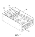
- FIG. 7 shows a cut away view of a computer with cooling fans for the hard drive modules in accordance with one embodiment of the present invention.
- the invention relates to a module containing multiple hard drives which can be inserted and removed as an organized set of hard drives into a receptacle.
- the receptacle provides precision mechanical alignment and electrical connection of the set of hard drives into a hard drive connector backplane.
- the hard drive backplane provides for a power and signal interconnect so that they can be interconnected to all necessary components for proper operation of the computer.
- the system provides for the removal and insertion of a set of drives with the computer turned off or turned on and operating. Individual drives can be removed and replaced from the multiple hard drive module without the need to first remove the multiple hard disk module from its receptacle. This allows defective drives to be individually replaced while other hard drives within the module continue to function normally in the computer.
- the multiple hard drive module allow the hard drives to be precision spaced so that a predetermined air space exist between hard drives to provide for air flow for cooling the hard drives.
- Two guide rails attached to each hard drive in the module precisely guide and align each hard drive into individual precision placed connectors on the receptacle backplane.
- a binder bar loosely but positively attaches all hard drives to the modules organizer sleeve.
- the organizer sleeve allows the hard drive set to be handled, inserted, removed, transported, stored and managed as a set and does not interfere with the precision alignment rail function of each hard drive which allows the receptacle to individually align each hard drive for a precise docking of each hard drive to its corresponding backplane connector.
- Detaching the binder bar allows one or more individual hard drives to be removed from the sleeve. This can be done regardless of weather the module is inserted into the receptacle and docked and actively operating in the backplane, or the module is removed from the receptacle and placed on a table.
- the receptacle includes precision fabricated slots which mate with each hard drive's pair of rails and precisely align each hard drive to the receptacles connector backplane.
- the backplane is designed in such as way that air can flow from the front of the drive to the rear of the drive with air flow allowed to freely flow through openings in the backplane and into the interior of the computer chassis where fans are typically located to assist with airflow.
- a retainer bar or retention latch system securely and firmly hold the multiple hard drive module to the receptacle for transport while installed in the computer.
- the hard drive module receptacle system allows the flexibility to have a single large multiple hard drive module plug into a single receptacle or alternatively multiple smaller modules continue a smaller number of hard drives to be concurrently installed into the same receptacle so long as the total number of drives in all modules does not exceed the total drive capacity of the receptacle.
- Individual drives may also be installed into the receptacle without being organized into a sleeve and be used in harmony with sets of drives organized into module sleeves.
- Hard drives selected for used in this invention are assumed to be designed to be hot pluggable but this is not an absolute requirement, but may limit use to installing and removing after the power has been turned off. Furthermore the design is not limited to a particular capacity, technology type, interface type, physical size or number of drives. Further, airflow may be designed from front to back of the drives, but other configurations currently being implemented provide for side to side airflow.
- FIG. 1A shows a perspective view of one example of the invention.
- the module 10 includes: multiple hard drives 12 ; a sleeve 14 ; slide rails 16 for each hard drive; and a binder bar 18 .
- FIG. 1B shows an exploded view of the same example.
- the sleeve 14 is shown with multiple slots 19 in the sides of the sleeve 14 .
- the module 10 serves to hold multiple hard drives 12 together as a single component that can be inserted into and removed from a computer.
- the individual hard drives are held together with a binder bar 18 .
- the binder bar 18 is attached onto each individual hard drive so that they are held together as a group.
- the binder bar 18 is attached with a knurled knob to the side of each hard drive 12 . This allows the binder bar to be installed and removed by hand.
- FIG. 2 shows an exploded view of a single hard drive 20 .
- a face plate 22 is mounted on the front of the hard drive rails 24 a and 24 b which in turn are attached to hard drive 20 .
- the face plate serves as the attached point for the binder bar 18 shown previously in FIGS. 1A and 1B .
- two slide rails 24 a and 24 b are mounted on each side of the hard drive 20 .
- the face plate and slide rails are attached to the hard drive with screws.
- other types of attachment mechanisms may be used in alternative embodiments.
- FIGS. 3A and 3B show different views of the module 32 as it is inserted into a computer 30 .
- FIG. 3A shows a partially exploded view of the module 32 with a single hard drive 36 and the binder bar 39 detached from the module.
- the slide rails 38 guide the hard drives 36 into the slots 37 of sleeve 34 .
- the slide rails 38 extend outside the sides sleeve.
- the slide rails 38 guide the module 32 into the computer 30 by match up with module guide slots inside the hard drive receptacle 33 that is located on the interior of the computer 30 .
- a retainer bar 35 may be used to hold the module 32 in place.
- the module 32 connects to the computer 30 through the hard drive receptacle 33 that is mounted with the computer.
- the receptacle 33 contains a porous backplane (not shown) mounted in the rear which is designed such that air can flow freely from front to back of the module.
- the backplane may be connected to the hard drive controller of the computer and required power supplies.
- the backplane attaches to a RAID controller.
- the RAID (Redundant Array of Inexpensive Disks) system is used to increase performance and provide fault tolerance for hard disk drives in computers.
- Various RAID level standards are used with various levels of system redundancy and/or fault tolerance that are well known to those of skill in the art.
- the present invention may use RAID-0, RAID-1, or RAID-5 levels in various embodiments.
- the invention may use a JBOD (Just a Bunch of Disks) configuration that provides no system redundancy with the hard drives.
- FIGS. 4A-4D show examples of the present invention using modules of different numbers of hard drives. While the previous examples show a module with 8 hard drives, different sized modules may be used together in combination to replicate a larger capacity module.
- FIG. 4A shows a similar computer 40 as shown previously in FIGS. 3A and 3B . However, two separate two-drive modules 42 are combined with a four-drive module 44 when inserted into the computer. This will duplicate the same performance as an eight-drive module but each smaller capacity module is an independent component which can be separately installed, removed and managed.
- FIG. 4B shows another example of different capacity modules. In this example, an eight-drive module 46 is inserted into a server 48 along with two separate two-drive modules 44 . In this example, the modules are shown for use in a network server.
- the module may be inserted in a horizontal orientation as shown in FIGS. 4C and 4D .
- a pair of two-drive modules 42 are combined with a four-drive module 44 and inserted in a horizontal receptacle 45 that is mounted within the computer.
- a porous backplane 47 and a retainer bar 49 are also shown.
- the backplane 49 is mounted in the rear of the receptacle 45 as shown in FIG. 4D . It provides a connection for the module to a drive controller as described previously.
- the retainer bar 49 attaches over the modules to hold them in place within the sleeve 45 .
- the sleeve is merely an organizer for grouping the drives together in a module. It floats within the space of the receptacle of the computer system and it does not provide final precision alignment.
- the precision rails of the drive mate with the corresponding precision slots within the sleeve. This allows the individual hard drives to be inserted and dock with the backplane in the rear of the receptacle without damaging the connection mechanisms.
- the key advantage of the system is to allow the each hard drive to independently float within the sleeve. This allows the modules and individual drives to be inserted and removed easily and quickly.
- the tolerance for the floating of the hard drive within the sleeve is between 0.03 and 0.06 inches. This is typically a looser tolerance that a design for computer hardware components that are inserted into component receptacles.
- FIG. 5 shows a single hard drive 54 that is pulled out of the module 52 in a computer 50 after the retainer bar 58 and binder bar 56 are removed.
- the individual drives or even an entire module may be removed while the computer is in operation. This is known as “hot-pluggable” device.
- the removal or insertion of the drives will not affect the operation of a working computer.
- the computer will automatically reconfigure and reinstall the hard drives and continue operation.
- the hard drives used in some embodiments may be a “Serial Advanced Technology Attachment,” or “Serial ATA” (SATA) drive.
- SATA Serial Advanced Technology Attachment
- Other embodiments may use a “Small Computer System Interface” (SCSI) drive that sometimes called a “skuzzy” drive or a more modern version of SCSI called Serial Attached SCSI (SAS).
- SCSI Serial Computer System Interface
- SAS Serial Attached SCSI
- SATA Serial Attached SCSI
- a SATA drive is shown with a 500 GB storage capacity.
- the physical size of the hard drives may vary with different embodiments. Examples of hard drives that are used include a 2.5′′ drive and a 3.5′′ drive.
- the 3.5′′ drive has an exterior width of 4.0 inches and an exterior thickness of 1.0 inches.
- the center to center distance between 3.5′′ drives 62 in a module is 1.25 inches with a 0.25 inch air gap 64 between drives.
- the 2.5′′ drive has an exterior width of 70 mm and an exterior thickness of 9.5 mm.
- the center to center distance between 2.5′′ drives 66 in a module is 12.5 mm with a 3 mm air gap 68 between drives.
- FIG. 7 shows a cut away view of an example of an internal cooling system.
- the hard drive module 72 is installed in the computer 70 .
- a bank of multiple cooling fans 74 are placed directly behind the module. The fans 74 draw cooler air from outside the computer in through the air gaps between the drives of the module. The air is then pulled out of the computer with exhaust fans 76 located opposite the module 72 and receptacle.
- Portable computers many times need to operate at really high temperatures such as 60° C.
- One advantage of the present invention is that fresh air is pulled through the air gap of the drives first before reaching the interior of the computer. This allows the hard drives to operate at or near the maximum of their specific temperature limits.
- the modules could be used with other computer devices such as a portable workstation computer or a video system.
- a video system is used to record and store digital video data. These systems are sometimes called a “digital film recorder (DFR)”, a “digital video recorder (DVR)” or a “digital disk recorder (DDR)”. These systems typically require a massive amount of data storage for a portable digital video system. It is fully intended that the invention could be used with any such device that needs a removable hard drive.
Abstract
Description
Claims (31)
Priority Applications (2)
| Application Number | Priority Date | Filing Date | Title |
|---|---|---|---|
| US11/409,296 US7542295B2 (en) | 2006-04-21 | 2006-04-21 | Removable hard drive module for a computer |
| US12/476,056 US8111514B2 (en) | 2006-04-21 | 2009-06-01 | Removable hard drive module for a computer with improved thermal performance |
Applications Claiming Priority (1)
| Application Number | Priority Date | Filing Date | Title |
|---|---|---|---|
| US11/409,296 US7542295B2 (en) | 2006-04-21 | 2006-04-21 | Removable hard drive module for a computer |
Related Child Applications (1)
| Application Number | Title | Priority Date | Filing Date |
|---|---|---|---|
| US12/476,056 Continuation-In-Part US8111514B2 (en) | 2006-04-21 | 2009-06-01 | Removable hard drive module for a computer with improved thermal performance |
Publications (2)
| Publication Number | Publication Date |
|---|---|
| US20070247802A1 US20070247802A1 (en) | 2007-10-25 |
| US7542295B2 true US7542295B2 (en) | 2009-06-02 |
Family
ID=38619277
Family Applications (1)
| Application Number | Title | Priority Date | Filing Date |
|---|---|---|---|
| US11/409,296 Active 2026-11-13 US7542295B2 (en) | 2006-04-21 | 2006-04-21 | Removable hard drive module for a computer |
Country Status (1)
| Country | Link |
|---|---|
| US (1) | US7542295B2 (en) |
Cited By (12)
| Publication number | Priority date | Publication date | Assignee | Title |
|---|---|---|---|---|
| US20090034220A1 (en) * | 2007-07-31 | 2009-02-05 | Ricardo Mariano | Latching mechanism |
| US20090273898A1 (en) * | 2006-04-21 | 2009-11-05 | Max Vision Corporation | Removable Hard Drive Module for a Computer with Improved Thermal Performance |
| US20110234064A1 (en) * | 2010-03-23 | 2011-09-29 | Makley Albert V | Drive Tray |
| US20120023370A1 (en) * | 2010-07-21 | 2012-01-26 | Truebenbach Eric L | Bulk transfer of storage devices using manual loading |
| US20120236491A1 (en) * | 2011-03-16 | 2012-09-20 | Lenovo (Singapore) Pte. Ltd. | Flush faced servers |
| US8638550B2 (en) | 2011-03-16 | 2014-01-28 | Lenovo (Singapore) Pte. Ltd. | Keyed media drive rails |
| US20160217097A1 (en) * | 2015-01-26 | 2016-07-28 | Hewlett-Packard Development Company, L.P. | Storage device carrier assembly |
| US20160270250A1 (en) * | 2013-11-01 | 2016-09-15 | Quanta Computer Inc. | High density chassis for a server rack |
| US20170306610A1 (en) * | 2008-02-02 | 2017-10-26 | Charles H. Leahy | Methods and systems for modular buildings |
| US9861011B1 (en) | 2016-06-22 | 2018-01-02 | HGST Netherlands B.V. | Stackable sleds for storing electronic devices |
| US9958912B2 (en) * | 2016-05-09 | 2018-05-01 | Quanta Computer Inc. | Two rack unit chassis and low profile tool-less hard drive carrier |
| US11821206B2 (en) | 2008-02-02 | 2023-11-21 | Charles H. Leahy | Methods and systems for modular buildings |
Families Citing this family (16)
| Publication number | Priority date | Publication date | Assignee | Title |
|---|---|---|---|---|
| CN101246382B (en) * | 2007-02-14 | 2011-09-28 | 普安科技股份有限公司 | Storage system adapted for receiving a plurality of hard disk drives of different dimensions |
| US20080225494A1 (en) * | 2007-03-13 | 2008-09-18 | Chih-Yi Yang | Solid-state hard disk drive |
| US20090046419A1 (en) * | 2007-08-14 | 2009-02-19 | International Business Machines Corporation | Hot swappable hdd twin pack tray |
| US20090257187A1 (en) * | 2008-04-11 | 2009-10-15 | Dell Products L.P. | Information Handling System with Chassis Design for Storage Device Access |
| US20090282180A1 (en) * | 2008-05-06 | 2009-11-12 | Ricky Kuan | Plug-and-play hard disk read/write drive |
| WO2010141641A2 (en) * | 2009-06-02 | 2010-12-09 | Stephen Petruzzo | Modular re-configurable computers and storage systems and methods |
| CN101963832B (en) * | 2009-07-24 | 2013-08-28 | 鸿富锦精密工业(深圳)有限公司 | Hardware fixing structure |
| CN101996672A (en) * | 2009-08-21 | 2011-03-30 | 鸿富锦精密工业(深圳)有限公司 | Data storage device |
| EP2413326B1 (en) | 2010-07-30 | 2016-12-21 | Thomson Licensing | An electronic device comprising a removable hard disk |
| US9134771B2 (en) * | 2010-08-06 | 2015-09-15 | Dhk Storage, Llc | Raid devices, systems, and methods |
| US8576570B2 (en) * | 2011-03-21 | 2013-11-05 | NCS Technologies, Inc. | Adaptive computing system with modular control, switching, and power supply architecture |
| TW201320871A (en) * | 2011-11-08 | 2013-05-16 | Hon Hai Prec Ind Co Ltd | Mounting device for hard disk drive |
| TW201347645A (en) * | 2012-05-14 | 2013-11-16 | Hon Hai Prec Ind Co Ltd | Electronic device enclosure |
| US9977473B1 (en) * | 2016-12-23 | 2018-05-22 | Western Digital Technologies, Inc. | Data storage system enclosure with decoupled divider |
| US20220100233A1 (en) * | 2019-05-22 | 2022-03-31 | Hewlett-Packard Development Company, L.P. | Storage device carriers |
| USD944243S1 (en) * | 2020-01-31 | 2022-02-22 | Hewlett-Packard Development Company, L.P. | Computer |
Citations (24)
| Publication number | Priority date | Publication date | Assignee | Title |
|---|---|---|---|---|
| US5506750A (en) * | 1993-04-22 | 1996-04-09 | Bull S.A. | Mass memory subsystem having plates with pluralities of disk drives connected to central electronic cards |
| US5557499A (en) * | 1994-06-28 | 1996-09-17 | Ast Research, Inc. | Hard-disk drive tray assembly with pivotally rotatable front bezel |
| US6157540A (en) * | 1998-07-27 | 2000-12-05 | Dell Usa, L.P. | Screwless front loading hard drive bracket |
| US6473298B1 (en) * | 2000-08-30 | 2002-10-29 | Sun Microsystems, Inc. | Peripheral device storage system |
| US20020181194A1 (en) * | 2001-06-04 | 2002-12-05 | Sun Microsystems, Inc. | Computer bus rack having an increased density of card slots |
| US20020181197A1 (en) * | 2001-06-01 | 2002-12-05 | King-Tung Huang | Housing of data processing system with mechanism for easy removal and insertion of disk drive |
| US20030147219A1 (en) * | 2002-02-06 | 2003-08-07 | Shin Jiuh Corp. | Blade server module |
| US20030227752A1 (en) * | 2002-06-10 | 2003-12-11 | Yair Andrew John | Electronics assembly |
| US20040012921A1 (en) * | 2002-07-16 | 2004-01-22 | Fujitsu Limited | Module mounting/removing mechanism and disk array |
| US20040264145A1 (en) * | 2003-05-08 | 2004-12-30 | Miller Greg F. | Compact electronic component system and method |
| US6853548B2 (en) * | 2003-01-02 | 2005-02-08 | Quantum Corporation | 1U rack mount equipment enclosure with increased structural support |
| US20050174743A1 (en) * | 2002-01-21 | 2005-08-11 | Downing Robert W. | System for insertion and extraction of a printed circuit board module into and out of a subrack |
| US6957291B2 (en) * | 2001-03-29 | 2005-10-18 | Quantum Corporation | Removable disk storage array emulating tape library having backup and archive capability |
| US20050257232A1 (en) * | 2004-05-14 | 2005-11-17 | Fujitsu Limited | Enclosure structure of electronic equipment, and disk array apparatus |
| US20060002093A1 (en) * | 2004-07-02 | 2006-01-05 | Seagate Technology Llc | Engagement system for a module in an electronics cabinet |
| US6999307B2 (en) * | 2003-10-31 | 2006-02-14 | Inventec Corporation | Disk drive anchoring mechanism |
| US20060050487A1 (en) * | 2004-09-09 | 2006-03-09 | Tatung Co., Ltd. | Computer server |
| US7035096B2 (en) * | 2003-10-31 | 2006-04-25 | Hewlett-Packard Development Company, L.P. | Locking mechanism for removable components |
| US7092245B2 (en) * | 2004-07-16 | 2006-08-15 | Evserv Tech Corporation | Circuit board group for electrically coupling electronic devices |
| US20060221579A1 (en) * | 2005-03-31 | 2006-10-05 | Yuan-Chen Liang | Blade server system |
| US20060250766A1 (en) * | 2005-05-06 | 2006-11-09 | Blaalid Jeffrey S | Apparatus for removably securing storage components in an enclosure |
| US7200008B1 (en) * | 2004-07-01 | 2007-04-03 | Bhugra Kern S | Multi-depth drive enclosure |
| US7280352B2 (en) * | 2004-06-07 | 2007-10-09 | Sun Microsystems, Inc. | Drive carrier |
| US7312999B1 (en) * | 2005-04-29 | 2007-12-25 | Network Appliance, Inc. | High density drive chassis assembly |
-
2006
- 2006-04-21 US US11/409,296 patent/US7542295B2/en active Active
Patent Citations (24)
| Publication number | Priority date | Publication date | Assignee | Title |
|---|---|---|---|---|
| US5506750A (en) * | 1993-04-22 | 1996-04-09 | Bull S.A. | Mass memory subsystem having plates with pluralities of disk drives connected to central electronic cards |
| US5557499A (en) * | 1994-06-28 | 1996-09-17 | Ast Research, Inc. | Hard-disk drive tray assembly with pivotally rotatable front bezel |
| US6157540A (en) * | 1998-07-27 | 2000-12-05 | Dell Usa, L.P. | Screwless front loading hard drive bracket |
| US6473298B1 (en) * | 2000-08-30 | 2002-10-29 | Sun Microsystems, Inc. | Peripheral device storage system |
| US6957291B2 (en) * | 2001-03-29 | 2005-10-18 | Quantum Corporation | Removable disk storage array emulating tape library having backup and archive capability |
| US20020181197A1 (en) * | 2001-06-01 | 2002-12-05 | King-Tung Huang | Housing of data processing system with mechanism for easy removal and insertion of disk drive |
| US20020181194A1 (en) * | 2001-06-04 | 2002-12-05 | Sun Microsystems, Inc. | Computer bus rack having an increased density of card slots |
| US20050174743A1 (en) * | 2002-01-21 | 2005-08-11 | Downing Robert W. | System for insertion and extraction of a printed circuit board module into and out of a subrack |
| US20030147219A1 (en) * | 2002-02-06 | 2003-08-07 | Shin Jiuh Corp. | Blade server module |
| US20030227752A1 (en) * | 2002-06-10 | 2003-12-11 | Yair Andrew John | Electronics assembly |
| US20040012921A1 (en) * | 2002-07-16 | 2004-01-22 | Fujitsu Limited | Module mounting/removing mechanism and disk array |
| US6853548B2 (en) * | 2003-01-02 | 2005-02-08 | Quantum Corporation | 1U rack mount equipment enclosure with increased structural support |
| US20040264145A1 (en) * | 2003-05-08 | 2004-12-30 | Miller Greg F. | Compact electronic component system and method |
| US6999307B2 (en) * | 2003-10-31 | 2006-02-14 | Inventec Corporation | Disk drive anchoring mechanism |
| US7035096B2 (en) * | 2003-10-31 | 2006-04-25 | Hewlett-Packard Development Company, L.P. | Locking mechanism for removable components |
| US20050257232A1 (en) * | 2004-05-14 | 2005-11-17 | Fujitsu Limited | Enclosure structure of electronic equipment, and disk array apparatus |
| US7280352B2 (en) * | 2004-06-07 | 2007-10-09 | Sun Microsystems, Inc. | Drive carrier |
| US7200008B1 (en) * | 2004-07-01 | 2007-04-03 | Bhugra Kern S | Multi-depth drive enclosure |
| US20060002093A1 (en) * | 2004-07-02 | 2006-01-05 | Seagate Technology Llc | Engagement system for a module in an electronics cabinet |
| US7092245B2 (en) * | 2004-07-16 | 2006-08-15 | Evserv Tech Corporation | Circuit board group for electrically coupling electronic devices |
| US20060050487A1 (en) * | 2004-09-09 | 2006-03-09 | Tatung Co., Ltd. | Computer server |
| US20060221579A1 (en) * | 2005-03-31 | 2006-10-05 | Yuan-Chen Liang | Blade server system |
| US7312999B1 (en) * | 2005-04-29 | 2007-12-25 | Network Appliance, Inc. | High density drive chassis assembly |
| US20060250766A1 (en) * | 2005-05-06 | 2006-11-09 | Blaalid Jeffrey S | Apparatus for removably securing storage components in an enclosure |
Cited By (23)
| Publication number | Priority date | Publication date | Assignee | Title |
|---|---|---|---|---|
| US8111514B2 (en) * | 2006-04-21 | 2012-02-07 | Maxvision Corporation | Removable hard drive module for a computer with improved thermal performance |
| US20090273898A1 (en) * | 2006-04-21 | 2009-11-05 | Max Vision Corporation | Removable Hard Drive Module for a Computer with Improved Thermal Performance |
| US7843687B2 (en) * | 2007-07-31 | 2010-11-30 | Apple Inc. | Latching mechanism |
| US20110058333A1 (en) * | 2007-07-31 | 2011-03-10 | Apple Inc. | Latching mechanism |
| US20090034220A1 (en) * | 2007-07-31 | 2009-02-05 | Ricardo Mariano | Latching mechanism |
| US8054623B2 (en) | 2007-07-31 | 2011-11-08 | Apple Inc. | Latching mechanism |
| US20170306610A1 (en) * | 2008-02-02 | 2017-10-26 | Charles H. Leahy | Methods and systems for modular buildings |
| US11821206B2 (en) | 2008-02-02 | 2023-11-21 | Charles H. Leahy | Methods and systems for modular buildings |
| US10787803B2 (en) * | 2008-02-02 | 2020-09-29 | Charles H. Leahy | Methods and systems for modular buildings |
| US20110234064A1 (en) * | 2010-03-23 | 2011-09-29 | Makley Albert V | Drive Tray |
| US9330730B2 (en) * | 2010-03-23 | 2016-05-03 | Lenovo (Singapore) Pte. Ltd. | Drive tray |
| US8687349B2 (en) * | 2010-07-21 | 2014-04-01 | Teradyne, Inc. | Bulk transfer of storage devices using manual loading |
| US20120023370A1 (en) * | 2010-07-21 | 2012-01-26 | Truebenbach Eric L | Bulk transfer of storage devices using manual loading |
| US9052877B2 (en) * | 2011-03-16 | 2015-06-09 | Lenovo (Singapore) Pte. Ltd. | Flush faced servers |
| US8638550B2 (en) | 2011-03-16 | 2014-01-28 | Lenovo (Singapore) Pte. Ltd. | Keyed media drive rails |
| US20120236491A1 (en) * | 2011-03-16 | 2012-09-20 | Lenovo (Singapore) Pte. Ltd. | Flush faced servers |
| US20160270250A1 (en) * | 2013-11-01 | 2016-09-15 | Quanta Computer Inc. | High density chassis for a server rack |
| US10383247B2 (en) * | 2013-11-01 | 2019-08-13 | Quantra Computer Inc. | High density chassis for a server rack |
| US20160217097A1 (en) * | 2015-01-26 | 2016-07-28 | Hewlett-Packard Development Company, L.P. | Storage device carrier assembly |
| US10810152B2 (en) | 2015-01-26 | 2020-10-20 | Hewlett-Packard Development Company, L.P. | Storage device carrier assembly |
| US9958912B2 (en) * | 2016-05-09 | 2018-05-01 | Quanta Computer Inc. | Two rack unit chassis and low profile tool-less hard drive carrier |
| US9861011B1 (en) | 2016-06-22 | 2018-01-02 | HGST Netherlands B.V. | Stackable sleds for storing electronic devices |
| US10212854B2 (en) | 2016-06-22 | 2019-02-19 | Western Digital Technologies, Inc. | Stackable sleds for storing electronic devices |
Also Published As
| Publication number | Publication date |
|---|---|
| US20070247802A1 (en) | 2007-10-25 |
Similar Documents
| Publication | Publication Date | Title |
|---|---|---|
| US7542295B2 (en) | Removable hard drive module for a computer | |
| US8111514B2 (en) | Removable hard drive module for a computer with improved thermal performance | |
| US10001819B2 (en) | Dual-sided rackmount modular data processing assembly | |
| US8508928B2 (en) | Incorporation of multiple, 2.5-inch or smaller hard disk drives into a single drive carrier with a single midplane or baseboard connector | |
| US10362707B2 (en) | Reduced depth data storage assembly and rack server | |
| US7983032B2 (en) | Incorporation of two or more hard disk drives into a single drive carrier with a single midplane connector | |
| US9746886B2 (en) | Solid state storage system | |
| US7271999B2 (en) | Enclosure for computer peripheral devices | |
| US6906918B2 (en) | Enclosure for computer peripheral devices | |
| US20100049914A1 (en) | RAID Enhanced solid state drive | |
| US8743536B2 (en) | Mechanical conversion sleeve | |
| US20050057909A1 (en) | Disk storage system with removable arrays of disk drives | |
| US20130170129A1 (en) | Systems and methods for providing a dynamic electronic storage unit | |
| US20080130219A1 (en) | Enclosure for computer peripheral devices | |
| US20210224211A1 (en) | Storage drive adapter | |
| US20080126715A1 (en) | Apparatus, system, and method for integrated blade raid controller and storage | |
| TWI536178B (en) | Server | |
| US9280174B2 (en) | Data storage device enclosure and module | |
| US20080244145A1 (en) | Data storage docking system | |
| US7894208B1 (en) | Server module | |
| US9098249B2 (en) | Toolless hot swappable storage module | |
| US10966339B1 (en) | Storage system with removable solid state storage devices mounted on carrier circuit boards | |
| CN108475091B (en) | Storage device and storage device management program | |
| US7791873B2 (en) | Storage component of a server arrangement with a plurality of hard disk drives | |
| US20210043231A1 (en) | Storage system |
Legal Events
| Date | Code | Title | Description |
|---|---|---|---|
| AS | Assignment |
Owner name: MAXVISION CORPORATION, ALABAMA Free format text: ASSIGNMENT OF ASSIGNORS INTEREST;ASSIGNOR:IMSAND, BRUCE;REEL/FRAME:018170/0177 Effective date: 20060728 |
|
| AS | Assignment |
Owner name: HERCULES TECHNOLOGY GROWTH CAPITAL, INC., CALIFORN Free format text: SECURITY AGREEMENT;ASSIGNOR:MAXVISION, LLC;REEL/FRAME:019984/0816 Effective date: 20071018 Owner name: HERCULES TECHNOLOGY GROWTH CAPITAL, INC.,CALIFORNI Free format text: SECURITY AGREEMENT;ASSIGNOR:MAXVISION, LLC;REEL/FRAME:019984/0816 Effective date: 20071018 |
|
| STCF | Information on status: patent grant |
Free format text: PATENTED CASE |
|
| AS | Assignment |
Owner name: RPC GENESIS, LLC, ALABAMA Free format text: ASSIGNMENT OF ASSIGNORS INTEREST;ASSIGNOR:HERCULES TECHNOLOGY GROWTH CAPITAL, INC.;REEL/FRAME:028864/0493 Effective date: 20120730 |
|
| REMI | Maintenance fee reminder mailed | ||
| AS | Assignment |
Owner name: RUGGED PORTABLE COMPUTERS, LLC, ALABAMA Free format text: ASSIGNMENT OF ASSIGNORS INTEREST;ASSIGNOR:RPC GENESIS, LLC;REEL/FRAME:029631/0929 Effective date: 20120901 |
|
| FPAY | Fee payment |
Year of fee payment: 4 |
|
| SULP | Surcharge for late payment | ||
| FPAY | Fee payment |
Year of fee payment: 8 |
|
| MAFP | Maintenance fee payment |
Free format text: PAYMENT OF MAINTENANCE FEE, 12TH YR, SMALL ENTITY (ORIGINAL EVENT CODE: M2553); ENTITY STATUS OF PATENT OWNER: SMALL ENTITY Year of fee payment: 12 |